LONGSYS ELECTRONICS WK1221 Wifi Module User Manual wk1220 kit demo
LONGSYS ELECTRONICS (HK) CO.,LIMITED Wifi Module wk1220 kit demo
UserManual.wiki
>
LONGSYS ELECTRONICS
>
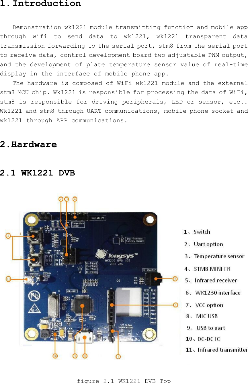
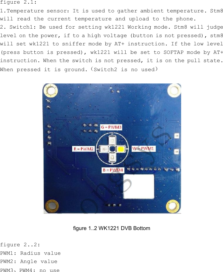
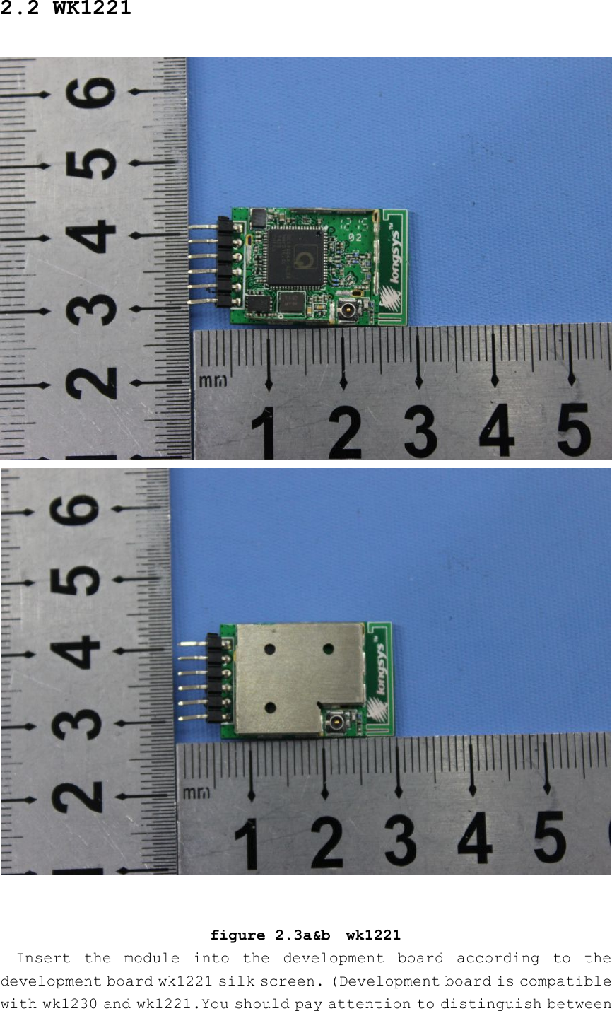
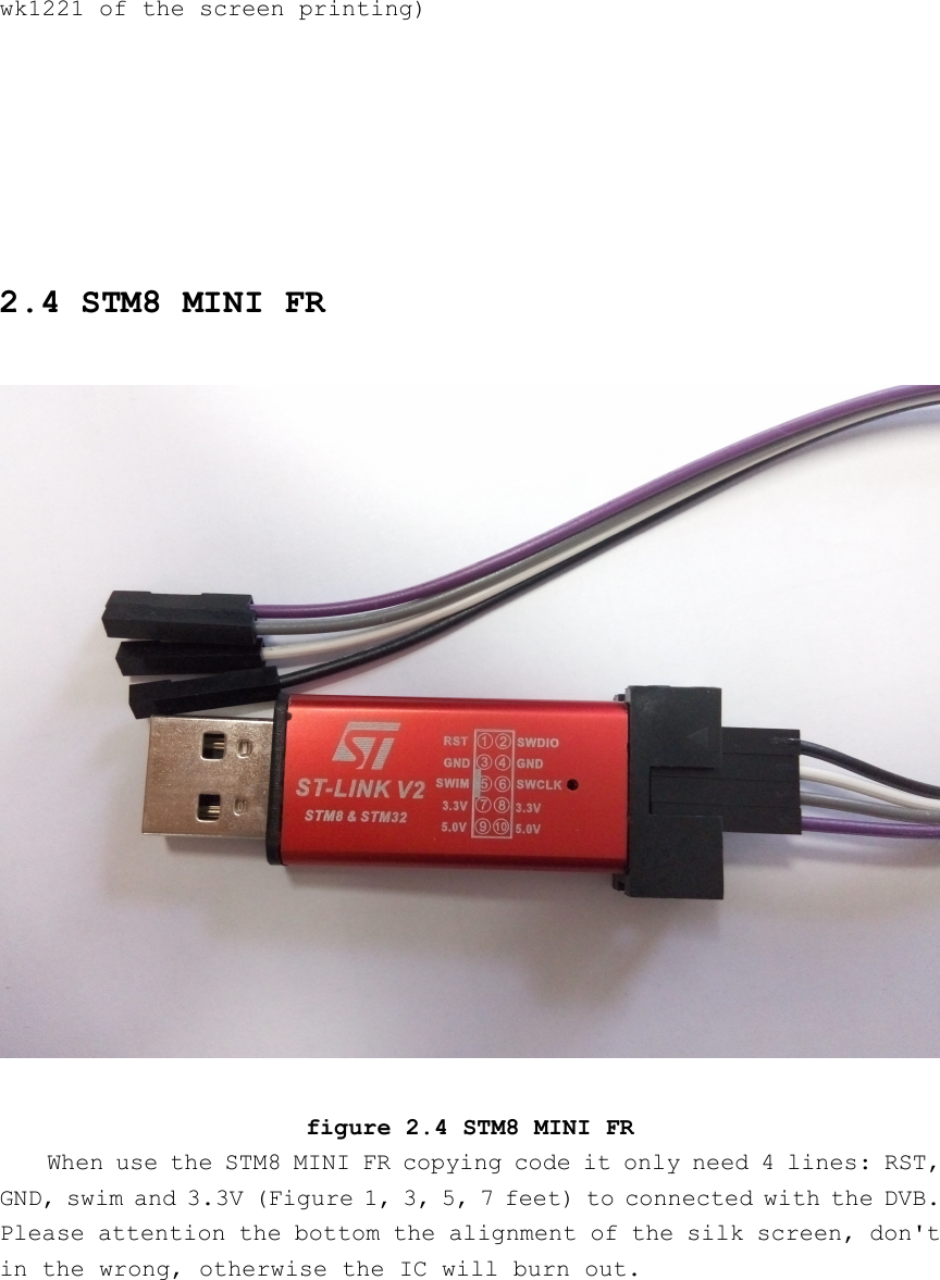
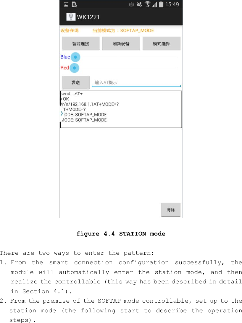
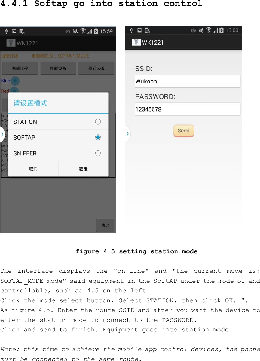
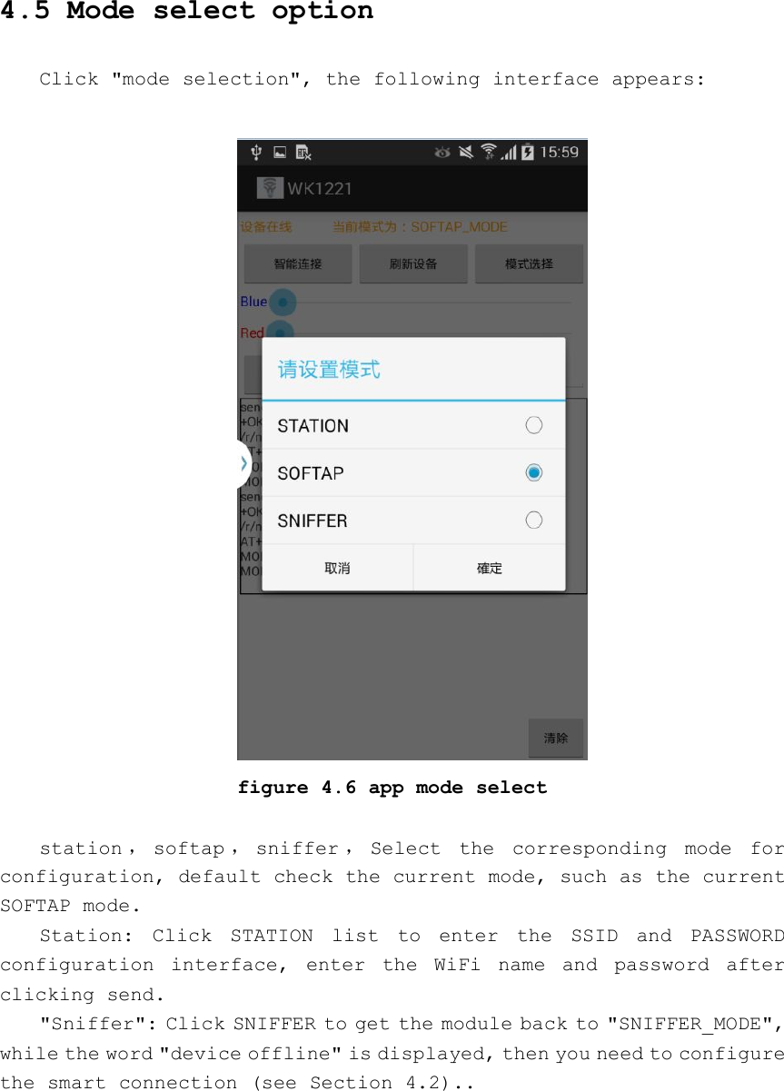
WK1221 User Manual
User Manual
Navigation menu
Upload a User Manual
Namespaces
Wiki Guide
HTML
PDF
Info
Views
User Manual
Discussion / Help
Navigation