LXI 93453734090 User Manual CAMCORDER Manuals And Guides L0712536
LXI Full size VHS Camcorder Manual L0712536 LXI Full size VHS Camcorder Owner's Manual, LXI Full size VHS Camcorder installation guides
User Manual: LXI 93453734090 93453734090 LXI CAMCORDER - Manuals and Guides View the owners manual for your LXI CAMCORDER #93453734090. Home:Electronics Parts:Lxi Parts:Lxi CAMCORDER Manual
Open the PDF directly: View PDF ![]() .
.
Page Count: 44
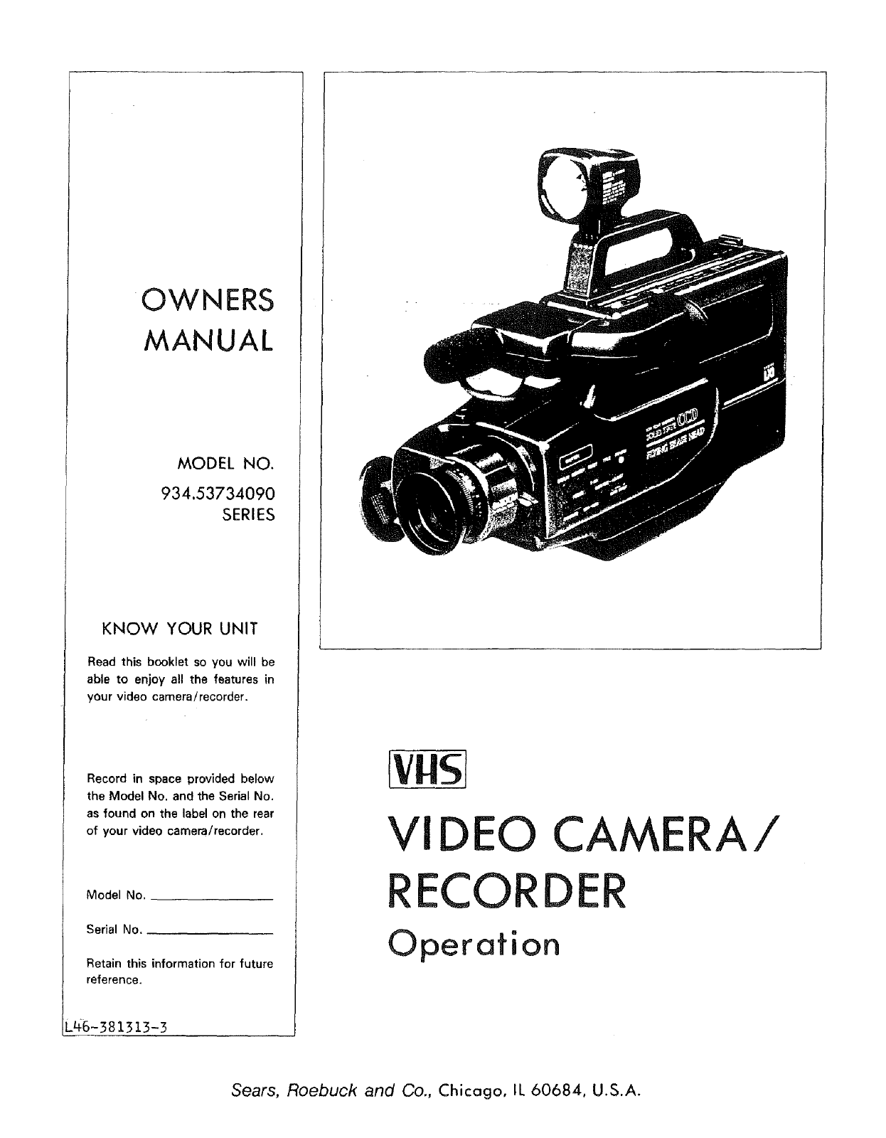
OWNERS
MANUAL
MODEL NO.
934.53734090
SERIES
KNOW YOUR UNIT
Read this booklet so you will be
able to enjoy all the features in
your video camera/recorder.
Record in space provided below
the Model No. and the Serial No.
as found on the label on the rear
of your video camera/recorder.
Model No.
Serial No.
Retain this information for future
reference.
_46-381313-3
EwIS/
VIDEO
RECO
CAME
DE
Operation
A/
Sears, Roebuck and Co., Chicago, IL 60684, U.S.A.
WARNING: TO PREVENT FIRE OR SHOCK HAZARD, DO NOT
EXPOSE THIS UNIT TO RAIN OR MOISTURE.
RISK OF ELECTRIC SHOCK
DO NOT OPEN
This symbol warns the user that uninsulated voltage within
the unit may have sufficient magnitude to cause electric
shock. Therefore, it is dangerous to make any kind of con-
tact with any inside part of this unit.
CAUTION: TO REDUCETHE RISK OF ELECTRIC SHOCK,
DO NOT REMOVE COVER (OR BACK),
NO USER -- SERVICEABLE PARTS INSIDE,
REFER SERVICING TO QUALIFIED SERVICE
PERSONNEL.
This symbol alerts the user that important literature con-
cerning the operation and maintenance of this unit has been
included. Therefore, it should be read carefully in order to
avoid any problems,
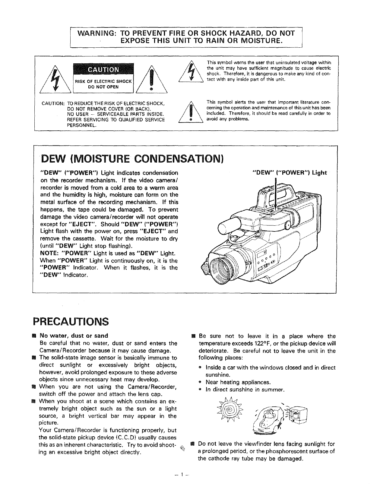
DEW (MOISTURE CONDENSATION)
"DEW" ("POWER") Light indicates condensation
on the recorder mechanism. If the video camera/
recorder is moved from a cold area to a warm area
and the humidity is high, moisture can form on the
metal surface of the recording mechanism. If this
happens, the tape could be damaged. To prevent
damage the video camera/recorder will not operate
except for "EJECT". Should "DEW" ("POWER")
Light flash with the power on, press "EJECT" and
remove the cassette. Wait for the moisture to dry
(until "DEW" Light stop flashing).
NOTE: "POWER" Light is used as "DEW" Light.
When "POWER" Light is continuously on, it is the
"POWER" Indicator. When it flashes, it is the
"DEW" Indicator.
"DEW" ("POWER") Light
PRECAUTIONS
[] No water, dust or sand
Be careful that no water, dust or sand enters the
Camera/Recorder because it may cause damage.
[] The solid-state image sensor is basically immune to
direct sunlight or excessively bright objects,
however, avoid prolonged exposure to these adverse
objects since unnecessary heat may develop.
[] When you are not using the Camera/Recorder,
switch off the power and attach the lens cap.
I When you shoot at a scene which contains an ex-
tremely bright object such as the sun or a light
source, a bright vertical bar may appear in the
picture.
Your Camera/Recorder is functioning properly, but
the solid-state pickup device (C.C.D) usually causes
this as an inherent characteristic. Try to avoid shoot- _,_
ing an excessive bright object directly.
[] Be sure not to leave it in a place where the
temperature exceeds 122°F, or the pickup device will
deteriorate. Be careful not to leave the unit in the
following places:
• Inside a car with the windows closed and in direct
sunshine.
o Near heating appliances.
• In direct sunshine in summer.
f _
[] Do not leave the viewfinder lens facing sunlight for
a prolonged period, or the phosphorescent surface of
the cathode ray tube may be damaged.
Congratulations on buying the _ Video Camera/Recorder. For maximum pleasure and convenience
please read these simple instructions before operating your Camera/Recorder.
NOTES: *This Video Camera/Recorder is compatible with any video cassette bearing the _] mark.
• [_ is designed to expand your opportunities for in-home TV viewing and not for any usage
which might violate the copyright laws,
•__J_ The Video Camera/Recorder with this marking incorporates [_ high-quality
picture technology and is compatible with any Video Cassette Recorders bearing the
[_ mark.
FEATURES
o CCD solid-state camera pickup
HQ_ High Quality picture technology
o Auto Focus Power Zoom Lens with macro feature
• Electronic Viewfinder
• Full record and playback capability with standard
cassette
e Flying Erase Head
o Video dub
Q Audio dub
• Time and Date
Titler
• Index Signal
o High speed shutter
DC Camera Light
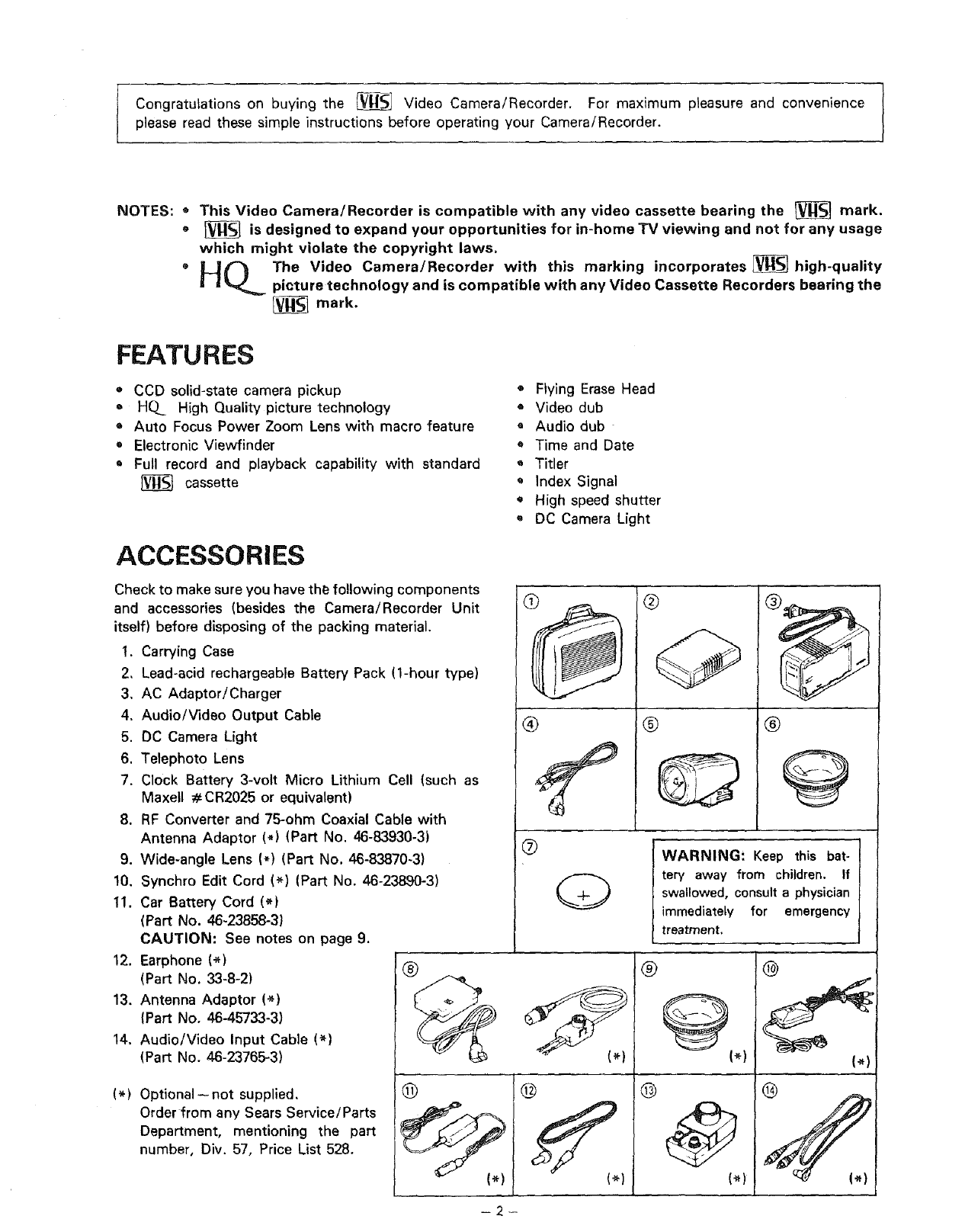
ACCESSORIES
Check to make sure you have the following components
and accessories (besides the Camera/ ecorder Unit
itself) before disposing of the packing _terial.
1. Carrying Case
2, Lead-acid rechargeable Battery Pack 'J-hour type)
3. AC Adaptor/Charger
4. Audio/Video Output Cable
5. DC Camera Light
6. Telephoto Lens
7. Clock Battery 3-volt Micro Lithium ;ell (such as
Maxell #CR2025 or equivalent)
8. RF Converter and 75-ohm Coaxial ble with
Antenna Adaptor (*) (Part No. 46-1 t30-3)
9. Wide-angle Lens (*) (Part No, 46-83870-3)
10, Synchro Edit Cord (*) (Part No. 46-2:3890-3)
11. Car Battery Cord (*)
(Part No. 46-23858-3)
CAUTION: See notes on page 9.
12. Earphone (_)
(Part No. 33-8-2)
13. Antenna Adaptor (*)
(Part No. 46-45733-3)
14. Audio/Video Input Cable (*)
(Part No. 46-23765-3)
(*) Optional -- not supplied,
Order from any Sears Service/Parts
Department, mentioning the part
number, Div. 57, Price List 528.
®
@
®<-
®
Q
®
®
-q
®@
I WARNING: Keep this bat-
itery away from children. If
; swallowed, consult a physician
iimmediately for emergency
treatment,
®J
®@(_)
®@
(*)
@
(_)
®
-- 2 ---
iMPORTANT SAFEGUARDS
In addition to the careful attention devoted to quality standards in the manufacture of your video product, safety is a major factor in the
design of every instrument. But, safety is your responsibility too.
This page lists important information that will help to assure your enjoyment and proper use o! a Video Camera!Recorder and accessory
equipment. Please read it carefully before operating your video product and keep it in a handy place for future reference
INSTALLATION
1Read and Follow Instructions--All the safety and operat-
ing instructions should be read before the video product
is operated. Follow all operating and use instructions.
7Power-Cord Protection--Power-supply cords should be
routed so that they are not likely to be walked on or pinched
by items placed upon or against them, paying particular attention
to cords at plugs, convenience receptacles, and the point where
they exit from the appliance.
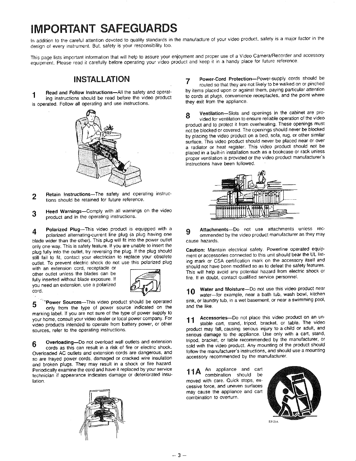
8Ventilation--Slots and openings in the cabinet are pro-
vided for ventilation to ensure reliable operation of the video
product and to protect it from overheating. These openings must
not be blocked or covered. The openings should never be blocked
by placing the video product on a bed, sofa, rug, or other similar
surface. This video product should never be placed near or over
a radiator or heat register. This video product should not be
placed in a built-in installation such as a bookcase or rack unless
proper ventilation is provided or the video product manufacturer's
instructions have been followed.
2 Retain Instructions--The safety and operating instruc-
tions should be retained for future reference.
3Heed Warnings--Comply with all warnings on the video
product and in the operating instructions.
4Polarized Plug--This video product is equipped with a
polarized alternating-current line plug (a plug having one
blade wider than the other). This plug will fit into the power outlet
only one way. This is safety feature. If you are unable to insert the
plug fully into the outlet, try reversing the plug. If the plug should
still fail to fit, contact your electrician to replace your obsolete
outlet. To prevent electric shock do not use this polarized plug
with an extension cord, receptacle or
other outlet unless the blades can be I.,f-_"_
fully inserted without blade exposure. If
you need an extension, use a polarized
cord.
5"_:'_Power Sources--This video product should be operated
only from the type of power source indicated on the
marking label, tf you are not sure of the type of power supply lo
your home, consult your video dealer or local power company. For
video products intended to operate from battery power, or other
sources, refer to the operating instructions.
6 Overloading--Do not overload wall outlets and extension
cords as this can result in a risk of fire or electric shock.
Overloaded AC outlets and extension cords are dangerous, and
so are frayed power cords, damaged or cracked wire insulation
and broken plugs. They may result in a shock or fire hazard.
Periodically examine the cord and have it replaced by your service
technician if appearance indicates damage or deteriorated insu-
lation.
9 Attachments--Do not use attachments unless rec-
ommended by the video product manufacturer as they may
cause hazards.
Caution: Maintain electrical safety. Powerline operated equip-
ment or accessories connected to this unit should bear the UL list-
ing mark or CSA certification mark on the accessory itself and
should not have been modified so as to defeat the safety features.
This will help avoid any potential hazard from electric shock or
fire. If in doubt, contact qualified service personnel.
10 Water and Moisture--Do not use this video product near
water--for example, near a bath tub, wash bowl, kitchen
sink, or laundry tub, in a wet basement, or near a swimming pool,
and the like.
11 Accessories--Do not place this video product on an un-
stable cart, stand,, tripod, bracket, or table. The video
product may fall, causing serious injury to a child or adult, and
serious damage to the appliance. Use only with a cart, stand,
tripod, bracket, or table recommended by the manufacturer, or
sold with the video product. Any mounting of the product should
follow the manufacturer's instructions, and should use a mounting
accessory recommended by the manufacturer.
11A An appliance and cart
combination should be
moved with care. Quick stops, ex-
cessive force, and uneven surfaces
may cause the appliance and cart
combination to overturn.
-3--
$3_25A
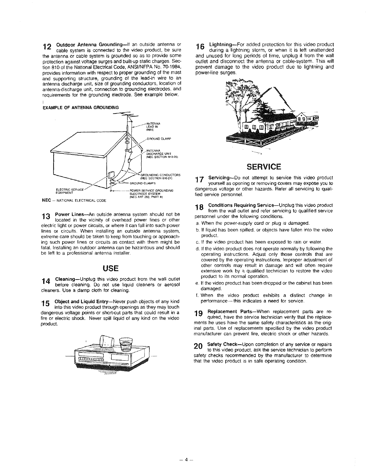
12 Outdoor Antenna Grounding--It an outside antenna or
cable system is connected to the video product, be sure
the antenna or cable system is grounded so as to provide some
protection against voltage surges and built-up static charges. Sec-
tion 810 of the National Electrical Code, ANSI/NFPA No. 70-1984,
provides information with respect to proper grounding of the mast
and supporting structure, grounding of the lead-in wire to an
antenna discharge unit, size of grounding conductors, location of
antenna-discharge unit, connection to grounding electrodes, and
requirements for the grounding electrode. See example below.
EXAMPLE OF ANTENNA GROUNDING
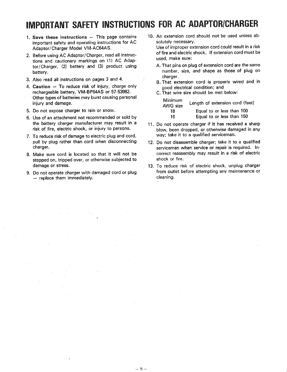
16Lightning--For added protection for this video product
during a lightning storm, or when it is left unattended
and unused for long periods of time, unplug it from the wall
outlet and disconnect the antenna or cable-system. This will
prevent damage to the video product due to lightning and
power-line surges.
LEAD IN
WI_E
• GROUNOING CONDUCTORS
(NEC SECTION Bt0-21}
ELECTRIC SERVICE
EQUIPMENT
NEC - NATIONAL ELECTRICAL CODE
ELECTRODE SYSTEM
(NEC ART 250, PAR3" R)
13 Power Lines--An outside antenna system should not be
located in the vicinity of overhead power lines or other
electric light or power circuits, or where it can fatl into such power
lines or circuits. When installing an outside antenna system,
extreme care should be taken to keep from touching or approach-
ing such power lines or circuits as contact with them might be
fatal. Installing an outdoor antenna can be hazardous and should
be left to a professional antenna installer.
USE
1 4 Cleaning--Unplug this video product Irom the walt outlet
before cleaning. Do not use liquid cleaners or aerosol
cleaners. Use a damp cloth for cleaning.
15Object and Liquid Entry--Never push objects of any kind
into this video product through openings as they may touch
dangerous voltage points or short-out parts that could result in a
fire or electric shock. Never spill liquid of any kind on the video
product.
SERVICE
1 7 Servicing--Do not attempt to service fhis video product
yourself as opening or removing covers may expose you to
dangerous voltage or other hazards. Refer al! servicing to quali-
fied service personnel.
1 8 Conditions Requiring Service--Unplug this video product
from the wall outlet and refer servicing to qua(tried service
personnel under the following conditions.
aWhen the power.supply cord or plug is damaged.
b. if liquid has been spilled, or objects have fallen into the video
product.
c. If the video product has been exposed to rain or water.
d. If the video product does not operate normally by following the
operating instructions. Adjust only those controls that are
covered by the operating instructions. Improper adjustment of
other controls may result in damage and will often require
extensive work by a qualified technician to restore the video
product to its normal operation.
e. If the video product has been dropped or the cabinet has been
damaged.
L When the video product exhibits a distinct change in
performance--this indicates a need for service.
19 Replacement Parts--When replacement parts are re-
quired, have the service technician verily that the replace-
ments he uses have the same safety characteristics as the orig-
inal parts. Use of replacements specified by the video product
manufacturer can prevent fire, electric shock or other hazards.
20 Safety Check--Upon completion of any service or repairs
to this video product, ask the service technician to perform
safety checks recommended by the manufacturer to determine
that the video product is in sale operating condition.
-4--
iMPORTANTSAFETYiNSTRUCTiONSFORAC ADAPTORICHARGER
I. Save these instructions -- This page contains
important safety and operating instructions for AC
Adaptor/Charger Model VM-AC64AS.
2. Before using AC Adaptor/Charger, read all instruc-
tions and cautionary markings on (1) AC Adap-
tor/Charger, (2) battery and (3) product using
battery.
3. Also read all instructions on pages 3 and 4.
4. Caution -- To reduce risk of injury, charge only
rechargeable battery, VM-BP64AS or 57-53982.
-Other types of batteries mayburst causing personal
injury and damage.
5. Do not expose charger to rain or snow.
6. Use of an attachment not recommended or sold by
the battery charger manufacturer may result in a
risk of fire, electric shock, or injury to persons.
7. To reduce risk of damage to electric plug and cord,
pull by plug rather than cord when disconnecting
charger.
8. Make sure cord is located so that it will not be
stepped on, tripped over, or otherwise subjected to
damage or stress.
9. Do not operate charger with damaged cord or plug
-- replace them immediately.
10. An extension cord should not be used unless ab-
solutely necessary.
Use of improper extension cord could result in a risk
of fire and electric shock. If extension cord must be
used, make sure:
A. That pins on plug of extension cord are the same
number, size, and shape as those of plug on
charger.
B. That extension cord is properly wired and in
good electrical condition; and
C. That wire size should be met below:
Minimum
AWG size Length of extension cord (feet)
18 Equal to or less than 100
16 Equal to or less than 150
11. Do not operate charger if it has received a sharp
blow, been dropped, or otherwise damaged in any
way; take it to a qualified serviceman.
12. Do not disassemble charger; take it to a qualified
serviceman when service or repair is required. In-
correct reassembly may result in a risk of electric
shock or fire.
13. To reduce risk of electric shock, unplug charger
from outlet before attempting any maintenance or
cleaning.
--5--
TABLE OF CONTENTS
Features ......................................................... 2
Accessories .................................................... 2
Important safeguards ...................................... 3
Important safety instructions for
AC Adaptor/Charger .................................... 5
Electronic viewfinder position adjustment ........ 7
Attaching the telephoto or wide-angle lens ...... 7
Loading battery for date/clock ........................ 7
Power sources ............................................... 8
Battery pack checking .................................... 9
Charging the battery pack ............................. 10
Making a sample camera recording ................ 11
Identification and operation of controls .......... 13
Auto focus ................................................... 19
Power zoom ................................................. 21
Macro lens ................................................... 21
Instant review ............................................... 21
Variable shutter speed ................................... 22
Auto iris ....................................................... 22
Recording TV program .................................. 23
Audio dubbing .............................................. 24
Video dubbing .............................................. 25
Index signal recording ................................... 26
Date/clock se_ing ........................................ 27
Attaching the DC camera light ...................... 28
Title making ................................................. 29
Eyepiece adjustment ..................................... 31
Producing best color program ....................... 31
Viewing the picture played back
on your TV ................................................ 32
Display button .............................................. 34
Linear time counter ....................................... 34
Memory ....................................................... 35
Time remaining ............................................. 35
F-search and R-search ................................... 36
Pause ........................................................... 35
Edit search ................................................... 37
Operating hints ............................................. 38
Camera/Recorder to VCR dubbing ................. 38
Flying erase head .......................................... 35
Troubleshooting ............................................ 38
Storing the Camera/Recorder in the
carrying case ............................................. 40
Routine maintenance .................................... 41
Sears service ................................................ 41
How to order repair parts .............................. 41
Specifications ............................................... 41
Using the optional synchro edit cord .............. 42
"Note to CATV system installer: This reminder is provided to call the CATV system installer's attention to
Article 820--22 of the NEC that provides guidelines for proper grounding and, in particular, specifies that
the cable ground shall be connected to the grounding system of the building, as close to the point of cable
entry as practical".
-6
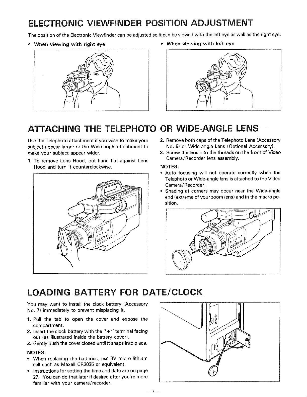
ELECTRONIC ViEWFINDER POSiTiON ADJUSTMENT
The position of the Electronic Viewfinder can be adjusted so it can be viewed with the left eye as well as the right eye.
• When viewing with right eye ® When viewing with left eye
ATTACHING THE TELEPHOTO OR WIDE-ANGLE LENS
Use the Telephoto attachment if you wish to make your
subject appear larger or the Wide-angle attachment to
make your subject appear wider.
1. To remove Lens Hood, put hand flat against Lens
Hood and turn it counterclockwise.
\
2. Remove both caps of the Telephoto Lens (Accessory
No. 6) or Wide-angle Lens (Optional Accessory).
3. Screw the lens into the threads on the front of Video
Camera/Recorder lens assembly.
NOTES:
• Auto focusing will not operate correctly when the
Telephoto or Wide-angle lens is attached to the Video
Camera/Recorder.
o Shading at corners may occur near the Wide-angle
end (extreme of your zoom lens) and in the macro po-
sition.
LOADING BATTERY FOR DATE/CLOCK
You may want to install the clock battery (Accessory
No. 7) immediately to prevent misplacing it.
1. Pull the tab to open the cover and expose the
compartment.
2. Insert the clock battery with the '°+" terminal facing
out (as illustrated inside the battery cover).
3. Gently push the cover closed until it snaps into place.
NOTES:
• When replacing the batteries, use 3V micro lithium
cell such as Maxell CR2025 or equivalent.
® Instructions for setting the time and date are on page
27. You can do that later if desired after you're more
familiar with your camera/recorder.
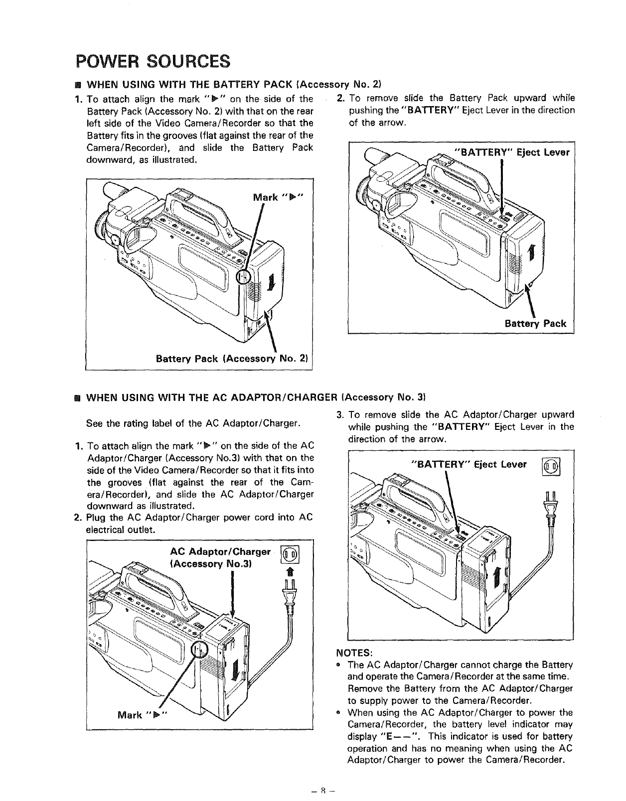
POWER SOURCES
! WHEN USING WITH THE BATTERY PACK (Accessory No. 2)
1. To attach align the mark "_'" on the side of the
Battery Pack (Accessory No. 2) with that on the rear
left side of the Video Camera/Recorder so that the
Battery fits in the grooves (flat against the rear of the
Camera/Recorder), and slide the Battery Pack
downward, as illustrated,
Battery Pack (Accessory No. 2)
2. To remove slide the Battery Pack upward while
pushing the "BATTERY" Eject Lever in the direction
of the arrow.
"BATTERY" Eject Lever
Battery Pack
[] WHEN USING WITH THE AC ADAPTOR/CHARGER (Accessory No. 3)
See the rating label of the AC Adaptor/Charger.
1. To attach align the mark "_" on the side of the AC
Adaptor/Charger (Accessory No.3) with that on the
side of the Video Camera/Recorder so that it fits into
the grooves (flat against the rear of the Cam-
era/Recorder), and slide the AC Adaptor/Charger
downward as illustrated.
2. Plug the AC Adaptor/Charger power cord into AC
electrical outlet.
AC Adaptor/Charger
Accessory No.3) t
3. To remove slide the AC Adaptor/Charger upward
while pushing the "BA3q-ERY" Eject Lever in the
direction of the arrow.
"BATTERY" Eject Lever
NOTES:
• The AC Adaptor/Charger cannot charge the Battery
and operate the Camera/Recorder at the same time.
Remove the Battery from the AC Adaptor!Charger
to supply power to the Camera/Recorder.
• When using the AC Adaptor/Charger to power the
Camera/Recorder, the battery level indicator may
display "E----". This indicator is used for battery
operation and has no meaning when using the AC
Adaptor/Charger to power the Camera/Recorder.
--8--
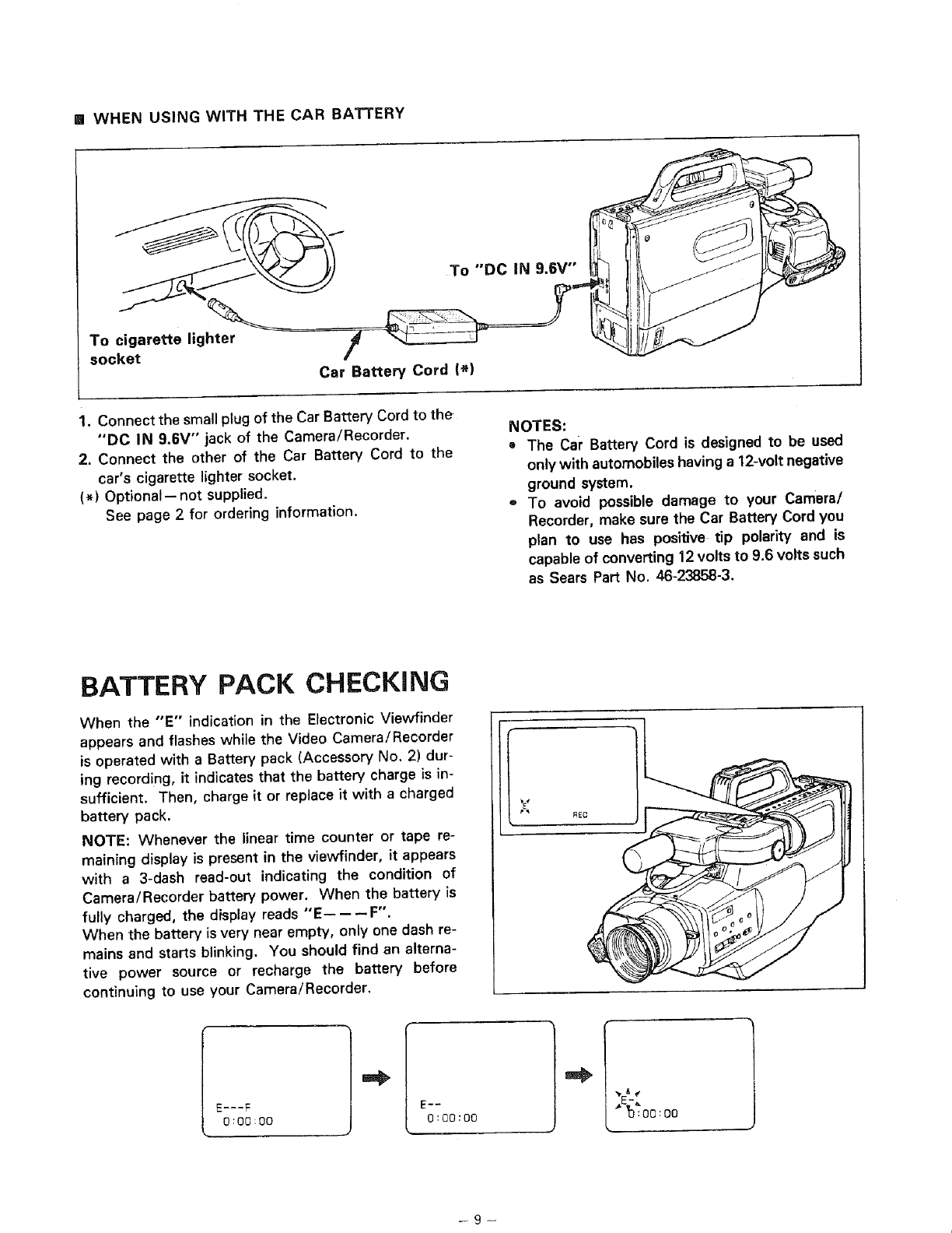
[] WHEN USING WITH THE CAR BATTERY
To cigarette lighter
socket
Car Battery Cord I*)
To "'DC IN 9.6V"
1. Connect the small plug of the Car Battery Cord to the
"'DC IN 9.6V" jack of the Camera/Recorder.
2. Connect the other of the Car Battery Cord to the
car's cigarette lighter socket.
(*) Optional-- not supplied.
See page 2 for ordering information.
NOTES:
The Car Battery Cord is designed to be used
only with automobiles having a12-volt negative
ground system.
To avoid possible damage to your Camera/
Recorder, make sure the Car Battery Cord you
plan to use has posil_ve tip polarity and is
capable of converting 12 volts to 9.6 volts such
as Sears Part No. 46-23858-3.
BATTERY PACK CHECKING
When the "E" indication in the Electronic Viewfinder
appears and flashes while the Video Camera/Recorder
is operated with a Battery pack (Accessory No. 2) dur-
ing recording, it indicates that the battery charge is in-
sufficient. Then, charge it or replace it with a charged
battery pack.
NOTE: Whenever the linear time counter or tape re-
maining display is present in the viewfinder, it appears
with a 3-dash read-out indicating the condition of
Camera/Recorder battery power. When the battery is
fully charged, the display reads "E------F".
When the battery is very near empty, only one dash re-
mains and starts blinking. You should find an alterna-
tive power source or recharge the battery before
continuing to use your Camera/Recorder.
E-_-F
0:O0:00 0:00:00
-9-
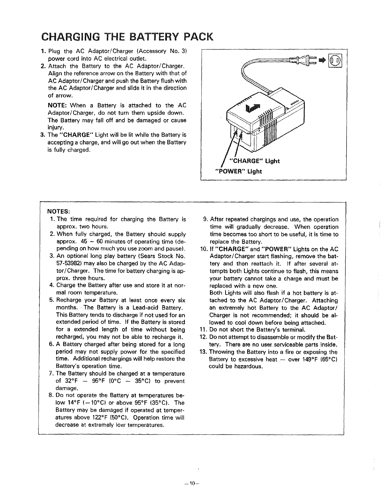
CHARGING THE BATTERY PACK
1. Plug the AC Adaptor/Charger (Accessory No. 3)
loower cord into AC electrical outlet.
2. Attach the Battery to the AC Adaptor/Charger.
Align the reference arrow on the Battery with that of
AC Adaptor/Charger and push the Battery flush with
the AC Adaptor/Charger and slide it in the direction
of arrow.
NOTE: When a Battery is attached to the AC
Adaptor/Charger, do not turn them upside down.
The Battery may fall off and be damaged or cause
injury.
3. The "CHARGE" Light will be lit while the Battery is
accepting a charge, and will go out when the Battery
is fully charged.
"CHARGE" Light
"POWER" Light
NOTES:
1. The time required for charging the Battery is
approx, two hours.
2. When fully charged, the Battery should supply
approx. 45 -60 minutes of operating time (de-
pending on how muchyou use zoom and pause).
3. An optional long play battery (Sears Stock No.
57-53982) may also be charged by the AC Adap-
tor/Charger. The time for battery charging is ap-
prox. three hours.
4. Charge the Battery after use and store it at nor-
mal room temperature.
5. Recharge your Battery at least once every six
months. The Battery is a Lead-acid Battery.
This Battery tends to discharge if not used for an
extended period of time. If the Battery is stored
for a extended length of time without being
recharged, you may not be able to recharge it,
6. A Battery charged after being stored for a long
period may not supply power for the specified
time. Additional rechargingswill help restore the
Battery's operation time.
7, The Battery should be charged at a temperature
of 32°F -- 95°F (0°C -- 35°C) to prevent
damage.
8. Do not operate the Battery at temperatures be-
low 14°F (--10°C) or above 95°F (35°C). The
Battery may be damaged if operated at temper-
atures above 122°F (50°C). Operation time will
decrease at extremely low temperatures.
9. After repeated chargings and use, the operation
time will gradually decrease. When operation
time becomes too short to be useful, it is time to
replace the Battery.
10. If "CHARGE" and "POWER" Lights on the AC
Adaptor/Charger start flashing, remove the bat-
tery and then reattach it. If after several at-
tempts both Lights continue to flash, this means
your battery cannot take a charge and must be
replaced with a new one.
Both Lights will also flash if a hot battery is at-
tached to the AC Adaptor/Charger. Attaching
an extremely hot Battery to the AC Adaptor/
Charger is not recommended; it should be al-
lowed to cool down before being attached.
11. Do not short the Battery's terminal.
12. Do not attempt to disassemble or modify the Bat-
tery. There are no userserviceable parts inside.
13. Throwing the Battery into a fire or exposing the
Battery to excessive heat -- over 149°F (65°C)
could be hazardous.
--10--
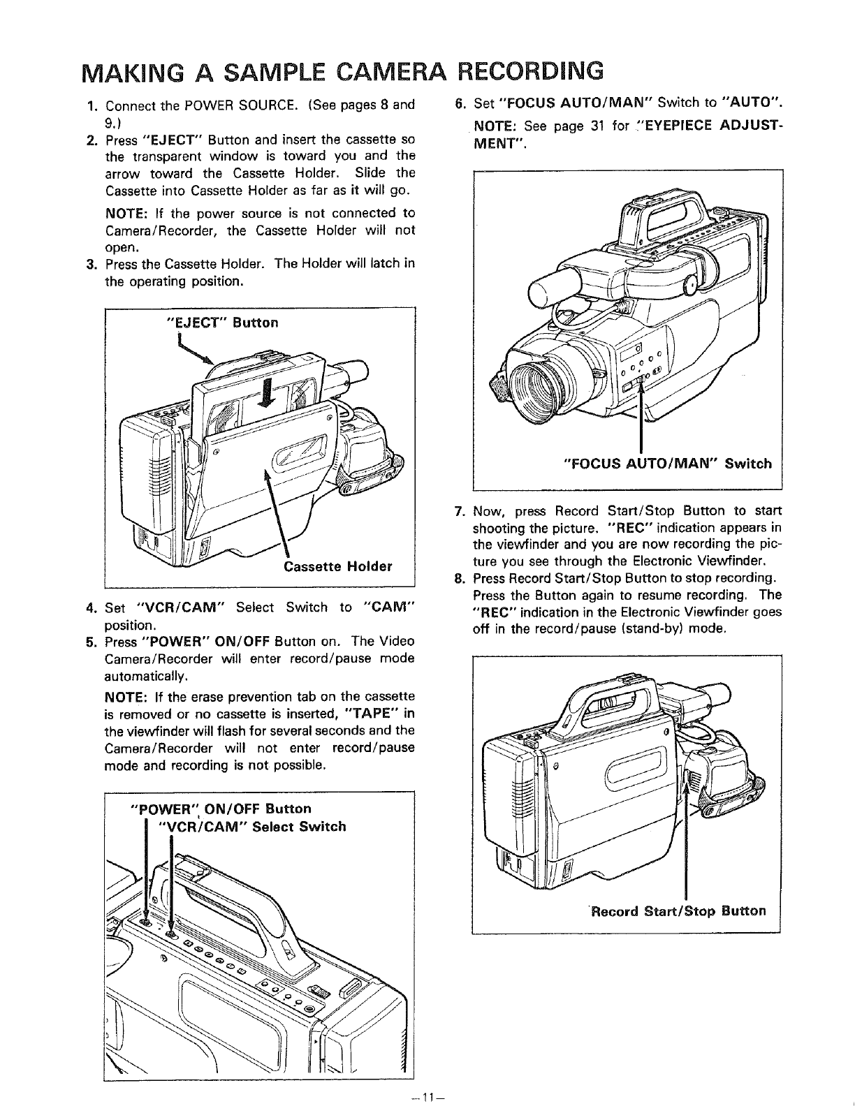
MAKING ASAMPLE CAMERA
1. Connect the POWER SOURCE. (See pages 8 and
9.)
2. Press "EJECT" Button and insert the cassette so
the transparent window is toward you and the
arrow toward the Cassette Holder. Slide the
Cassette into Cassette Holder as far as it will go.
NOTE: If the power source is not connected to
Camera/Recorder, the Cassette Holder will not
open.
3. Press the Cassette Holder. The Holder will latch in
the operating position.
"EJECT" Button
Cassette Holder
4. Set "'VCR/CAM" Select Switch to "CAM"
position.
5. Press "POWER" ON/OFF Button on. The Video
Camera/Recorder will enter record/pause mode
automatically.
NOTE: If the erase prevention tab on the cassette
is removed or no cassette is inserted, "TAPE" in
the viewfinder will flash for severalseconds and the
Camera/Recorder will not enter record/pause
mode and recording is not possible.
["'POWER'_ ON/OFF Button
"'VCR/CAM'" Select Switch
RECORDING
6. Set "FOCUS AUTO/MAN" Switch to "AUTO".
NOTE: See page 31 for "EYEPIECE ADJUST-
MENT".
"FOCUS AUTO/MAN" Switch
7. Now, press Record Start/Stop Button to start
shooting the picture. "REC" indication appears in
the vievvfinder and you are now recording the pic-
ture you see through the Electronic Viewfinder.
8. Press Record Start/Stop Button to stop recording.
Press the Button again to resume recording. The
"REC" indication in the Electronic Viewfinder goes
off in the record/pause (stand-by) mode.
Record Start/Stop Button
-11
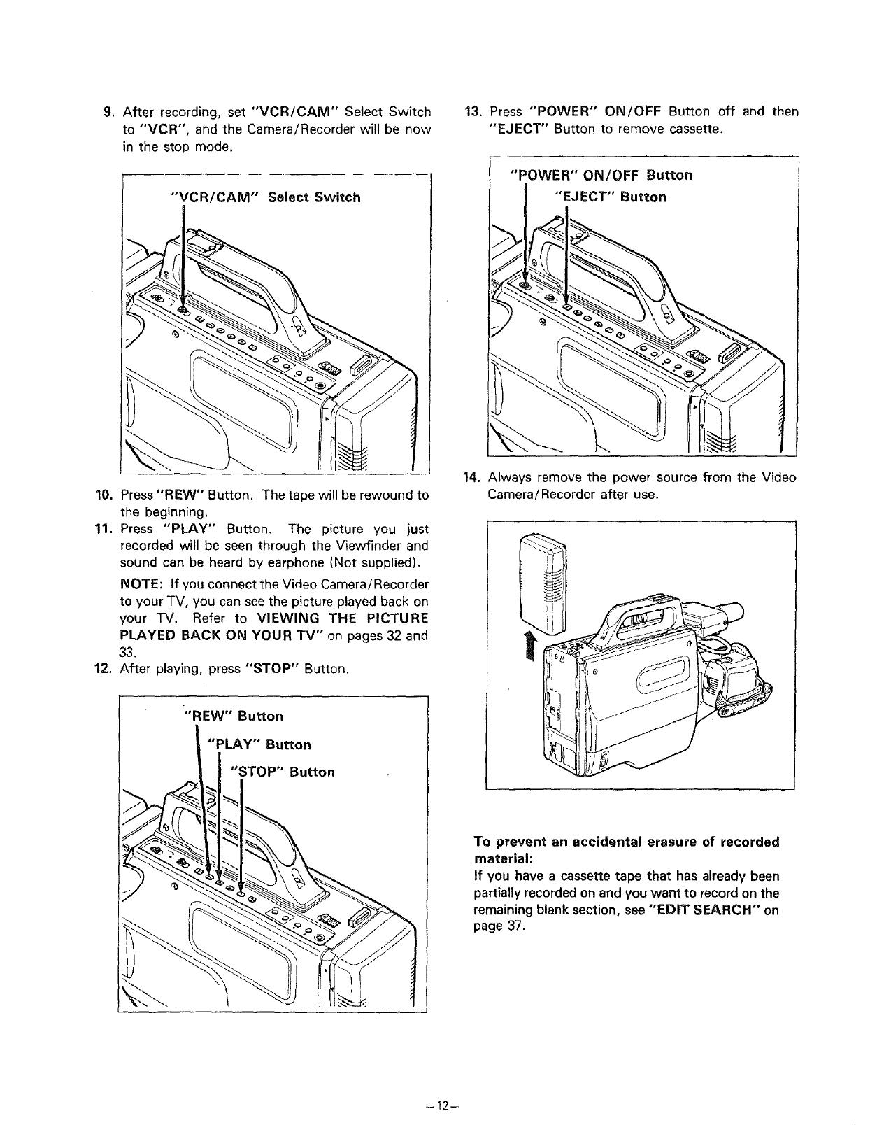
9. After recording, set "VCR/CAM'" Select Switch
to "'VCR", and the Camera/Recorder will be now
in the stop mode.
"VCR/CAiVI" Select Switch
13. Press "POWER" ON/OFF Button off and then
"EJECT" Button to remove cassette.
"POWER" ON/OFF Button
"EJECT" Button
10. Press "REW" Button. The tape will be rewound to
the beginning.
11. Press "PLAY" Button. The picture you just
recorded will be seen through the Viewfinder and
sound can be heard by earphone (Not supplied).
NOTE: If you connect the Video Camera/Recorder
to your TV, you can see the picture played back on
your TV. Refer to VIEWING THE PICTURE
PLAYED BACK ON YOUR TV" on pages 32 and
33.
12. After playing, press "'STOP" Button.
14. Always remove the power source from the Video
Camera/Recorder after use.
"REW"Bu_on
"PLAY"Bu_on
"STOP"Bu_on
To prevent an accidental erasure of recorded
material:
If you have a cassette tape that has already been
partially recorded on and you want to recordon the
remaining blank section, see "EDIT SEARCH" on
page 37.
-12--
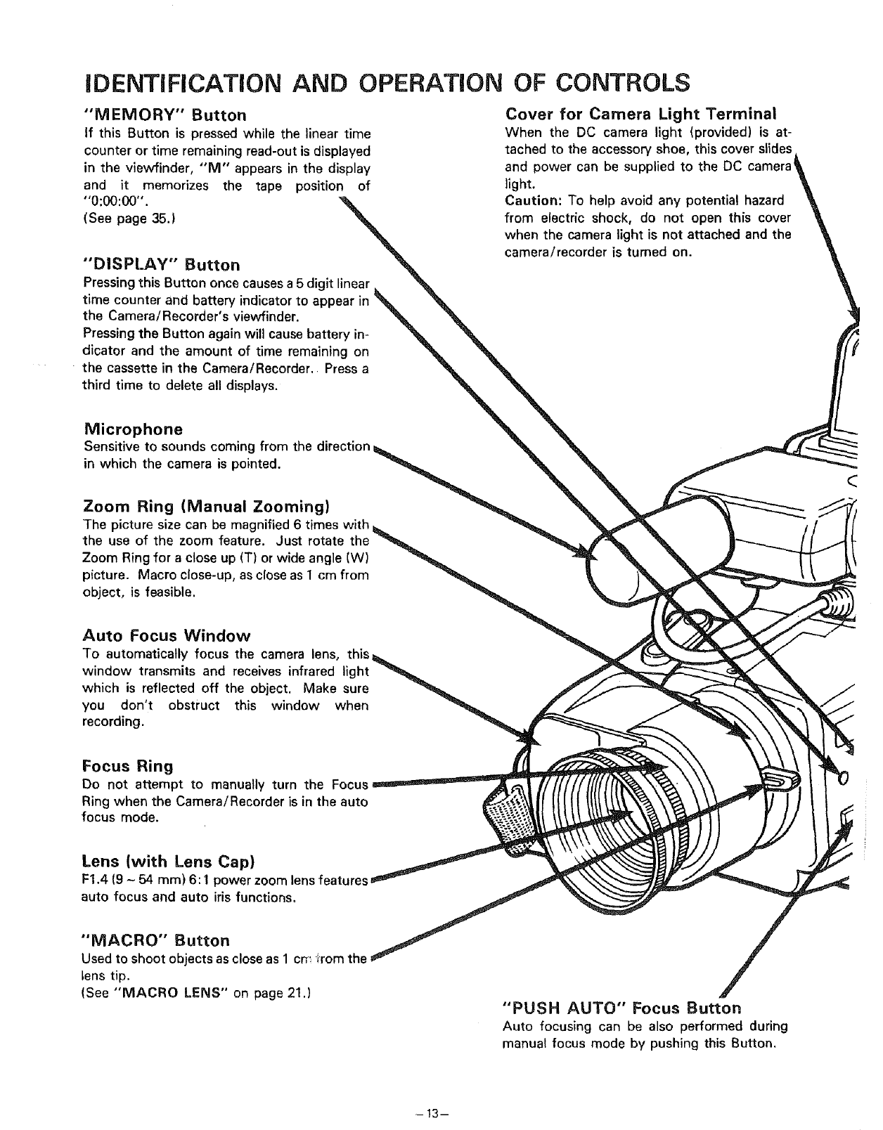
iDENTiFiCATiON AND OPERATION OF CONTROLS
"MEMORY" Button
If this Button is pressed while the linear time
counter or time remaining read-out is displayed
in the viewfinder, "M" appears in the display
and it memorizes the tape position of
"0:00:00".
(See page 35.)
"DISPLAY" Button
Pressingthis Button once causesa 5 digit linear
time counter and battery indicator to appear in
the Camera/Recorder's viewfinder.
Pressingthe Button again will cause battery in-
dicator and the amount of time remaining on
the cassette in the Camera/Recorder. Press a
third time to delete all displays.
Cover for Camera Light Terminal
When the DC camera light (provided) is at-
tached to the accessory shoe, this cover slides
and power can be supplied to the DC
light.
Caution: To help avoid any potential hazard
from electric shock, do not open this cover
when the camera light is not attached and the
camera/recorder is turned on.
Microphone
Sensitive to sounds coming from the direction
in which the camera is pointed.
Zoom Ring (Manual Zooming)
The picture size can be magnified 6 times with
the use of the zoom feature. Just rotate the
Zoom Ringfor aclose up (T) orwide angle (W)
picture. Macro close-up, as closeas 1cm from
object, is feasible.
Auto Focus Window
To automatically focus the camera lens, this
window transmits and receives infrared light
which is reflected off the object. Make sure
you don't obstruct this window when
recording.
Focus Ring
Do not attempt to manually turn the Focus
Ring when the Camera/Recorder is in the auto
focus mode.
Lens (with Lens Cap)
F1.4 (9 -54 ram) 6:1 power zoom lensfeatures
auto focus and auto iris functions.
"MACRO" Button
Used to shoot objects as close as 1 cr
lens tip.
(See "MACRO LENS" on page 21.) "PUSH AUTO" Focus Button
Auto focusing can be also performed during
manual focus mode by pushing this Button.
-13-
___.)
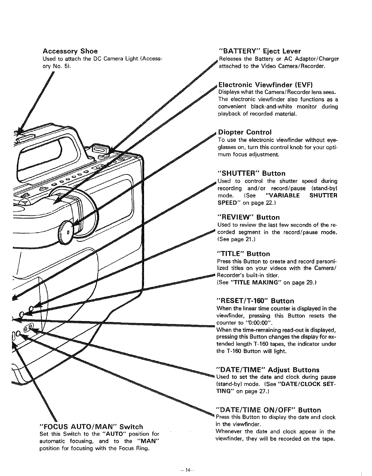
Accessory Shoe
Used to attach the DC Camera Light (Access-
ory No. 5).
"FOCUS AUTO/MAN" Switch
Set this Switch to the "AUTO" position for
automatic focusing, and to the "MAN"
position for focusing with the Focus Ring.
"BATTERY" Eject Lever
Releases the Battery or AC Adaptor/Charger
to the Video Camera/Recorder.
Electronic Viewfinder (EVF}
_lays what the Camera/Recorder lenssees.
The electronic viewfinder also functions as a
convenient black-and-white monitor during
playback of recorded material.
Diopter Control
To use the electronic viewfinder without eye-
glasseson, turn this control knob for your opti-
mum focus adjustment.
"SHUTTER" Button
Used to control the shutter speed during
and/or record/pause (stand-by)
mode. (See "VARIABLE SHUTTER
SPEED" on page 22.)
"REVIEW" Button
Used to review the last few seconds of the re-
corded segment in the record/pause mode.
(See page 21.)
"TITLE" Button
Press this Button to create and record personi-
lized titles on your videos with the Camera/
Recorder's built-in titler.
{See "TITLE MAKING" on page 29.)
"RESET/T-160" Button
When the lineartime counter is displayed in the
viewfinder, pressing this Button resets the
counter to "0:00:00".
When the time-remaining read-out is displayed,
pressingthis Button changes the displayfor ex-
tended length T-160 tapes, the indicator under
the T-160 Button will light.
"DATE/TIME" Adjust Buttons
Used to set the date and clock during pause
(stand-by) mode. (See "DATE/CLOCK SET-
TING" on page 27.)
"DATE/TiME ON/OFF" Button
is Button to display the date and clock
in the viewfinder.
Whenever the date and clock appear in the
viewfinder, they will be recorded on the tape.
--14 i
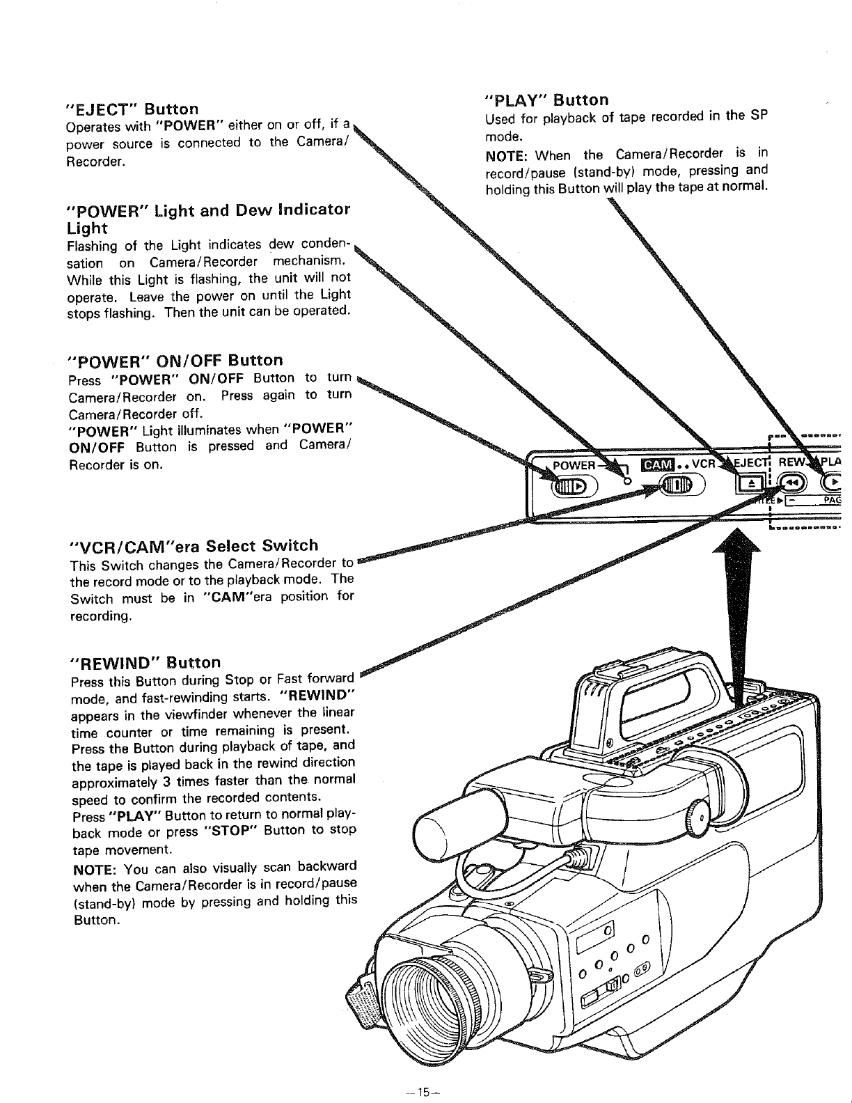
"EJECT" Button "PLAY" Button
•#, tr • -
Operates with POWER e_theron or off, ff a_. Used for playback of tape recorded In the SP
power source is connected to the Camera/_ mode.
Recorder. _NOTE: When the Camera/Recorder is in
"_ record!pause (stand-by) mode, pressing and
.... '_ holding this Button will play the tape at normal.
POWER Light and Dew Indicator _.
Light _- N
Flashing of the Light indicates dew conden-_ _ _.
sation on Camera!Recorder mechanism. _ "_ _,
While this Light is flashing, the unit will not _ _ _,
operate. Leave the power on until the Light _ _%_
s]°ps flashing" Then the unit can be °perated. _ _, X
'POWER" ON/OFF Button _ _
Press "POWER ON/OFF Button to turn_ _ _. _,
Camera/Recorder on. Press again to turn _ _ _ _IL
Camera/Recorder off. ,, _ _ "_ _,
"POWER" Light illuminates when "POWER _ "_ _ _IL
ON/OFF Button is pressed and Camera/ _ __
Recorder is on. _R___ I
,
"'VCR/CAM"era Select Switch _ _ ,d _...........
This Switch changes the Camera/Recorder to _ _ -
the record mode or tot he playback mode. The
Switch must be in CAM"era position for_
recording.
"REWIND" Button
Press this Button during Stop or Fast forward
mode, and fast-rewinding starts. "REWIND"
appears in the viewfinder whenever the linear
time counter or time remaining is present.
Press the Button during playback of tape, and
the tape is played back in the rewind direction
approximately 3 times faster than the normal
speed to confirm the recorded contents,
Press "PLAY" Button to return to normal play-
back mode or press "STOP" Button to stop
tape movement.
NOTE: You can also visually scan backward
when the Camera/Recorder is in record/pause
(stand-by} mode by pressing and holding this
Button.
-15--
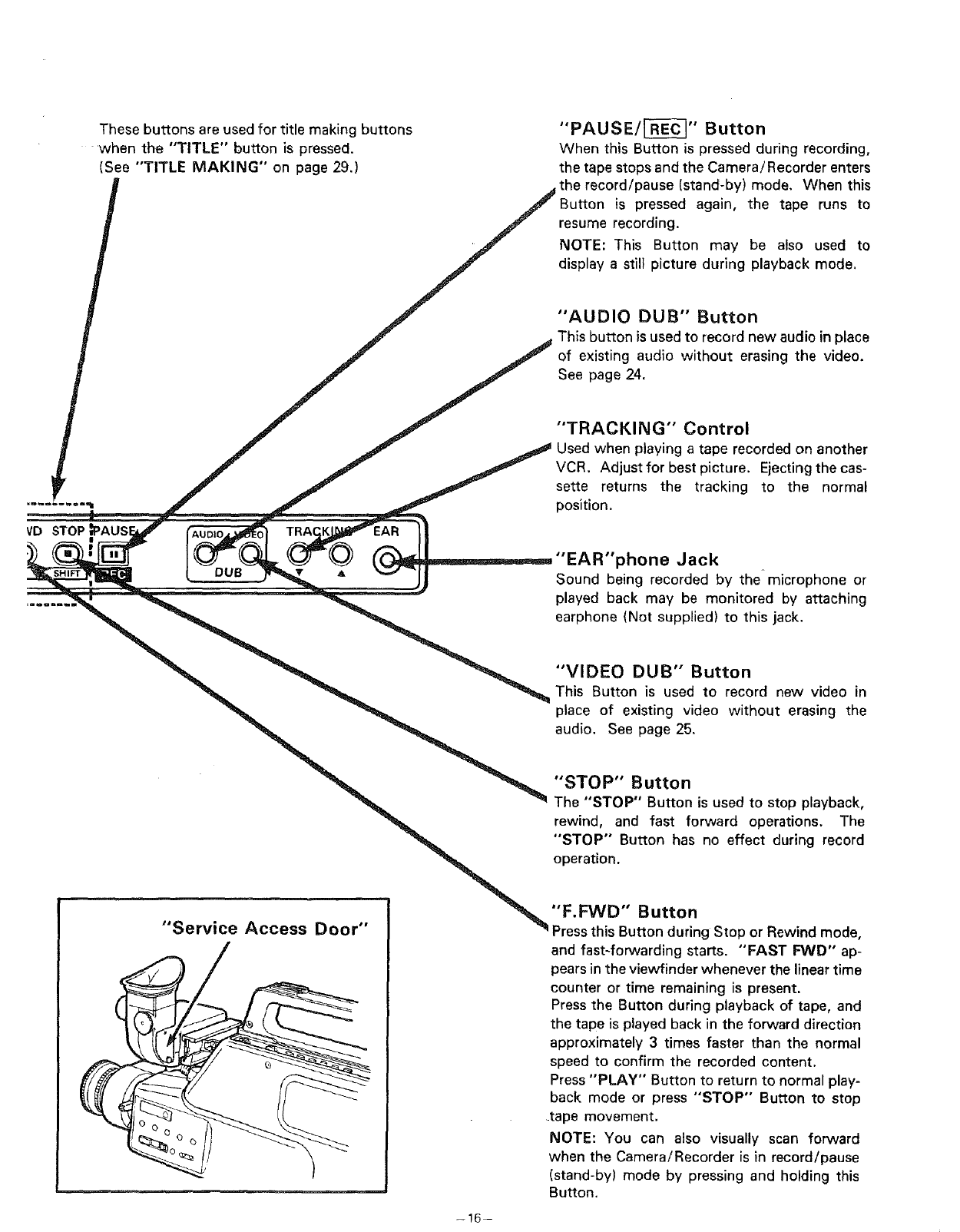
These buttons are used for title making buttons "PAUSE/_" Button
when the "TITLE" button is pressed. When this Button is pressed during recording,
(See "TITLE MAKING" on page 29.) the tape stops and the Camera/Recorder enters
,# the record/pause (stand-by) mode. When this
_" Button is pressed again, the tape runs to
/._ resume recording.
_" NOTE: This Button may be also used to
/ ,_ i isplay a still picture during playback m°de'
_" 'AUDIO DUB" Button
J.,j This button is used to record new audio in place
,if f of existing audio without erasing the video.
J _ "'TRACKING" Control
jr" _" _ Used when playing a tape recorded on another
_, f J J VCR. Adjust for best picture. Ejectingthe cas-
F,_ -_ _ sette returns the tracking to the normal
......... _. .S" ._ _ position.
V-D STOP _PAUS__
t cub . v -jj Sound being recorded by the microphone or
........ played back may be monitored by attaching
"_=_ _ ilrph°ne (N°t supp lied) tO this jack'
_. _ _ VIDEO DUB' Button
_ _ This Button is used to record new video in
_ place of existing video without erasing the
audioSeepage25
"STOP"Buttoo
_ The 'STOP" Button is used to stop playback,
rewind,, and fast forward operations. The
'STOP Button has no effect during record
"__ operation.
........ "_ "F.FVVD" Button
Service Access Door" Pressthis Button during Stop or Rewind mode,
and fast-forwarding starts. "FAST FVVD" ap-
pears inthe viewfinder whenever the lineartime
counter or time remaining is present.
Pressthe Button during playback of tape, and
the tape is played back in the forward direction
approximately 3 times faster than the normal
speed to confirm the recorded content.
Press "PLAY" Button to return to normal play-
back mode or press "STOP" Button to stop
tape movement.
NOTE: You can also visually scan forward
when the Camera/Recorder is in record/pause
(stand-by) mode by pressing and holding this
Button.
-16--
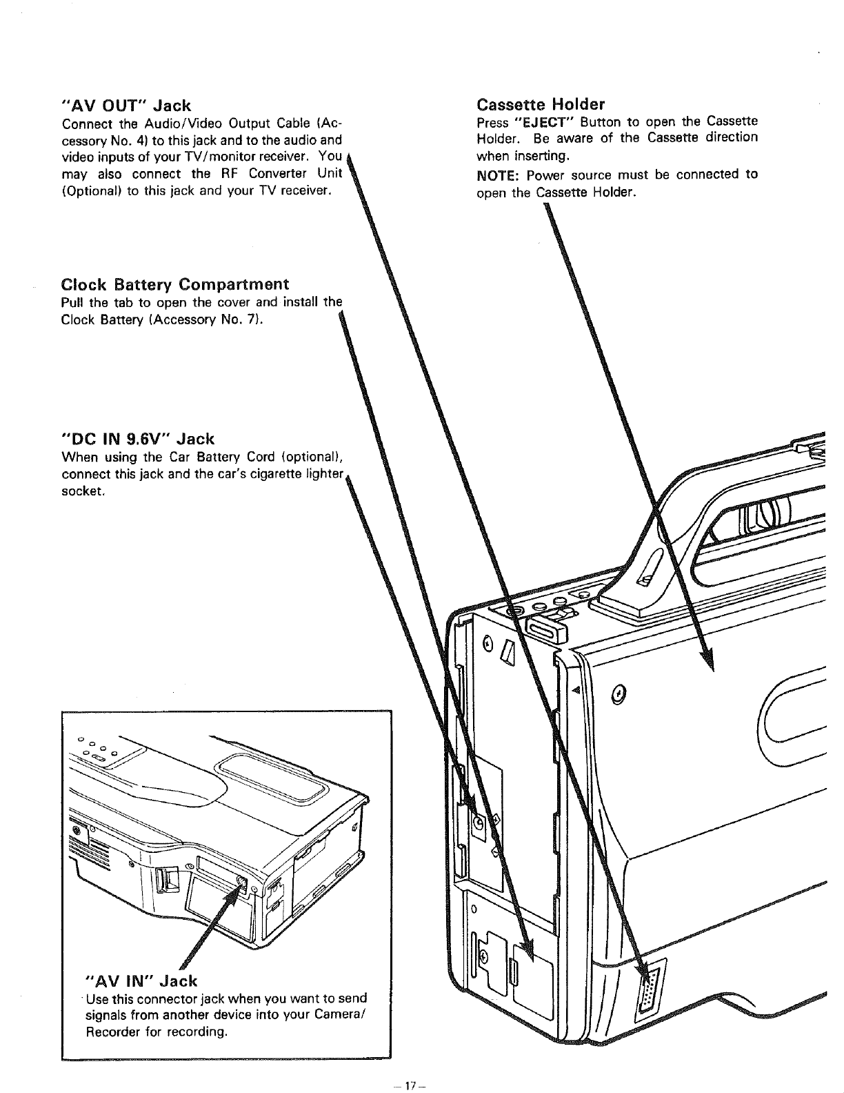
"AV OUT" Jack
Connect the Audio/Video Output Cable (Ac-
cessory No. 4) to this jack and to the audio and
video inputs of your TV/monitor receiver. You
may also connect the RF Converter Unit
(Optional) to this jack and your TV receiver.
Cassette Holder
Press "EJECT" Button to open the Cassette
Holder. Be aware of the Cassette direction
when inserting.
NOTE: Power source must be connected to
open the Cassette Holder.
Clock Battery Compartment
Pull the tab to open the cover and install the
Clock Battery (Accessory No. 7).
"'DC IN 9.6V" Jack
When using the Car Battery Cord (optional),
connect this jack and the car's cigarette lighter
socket.
"AV IN" Jack
Use this connector jack when you want to send
signalsfrom another device into your Camera/
Recorder for recording.
0
17-
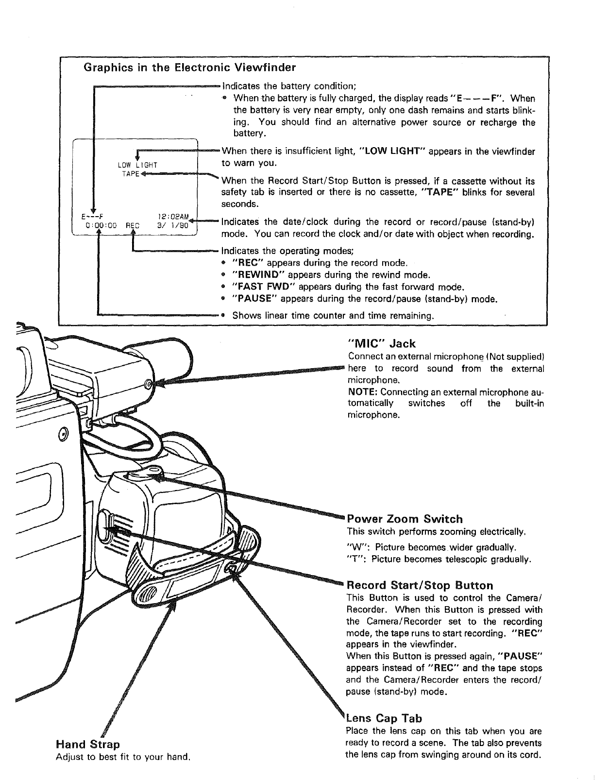
Graphics in the Electronic Viewfinder
Indicates the battery condition;
-When =thebattery is fully charged, the display reads "E-- ---- F". When
the battery is very near empty, only one dash remains and starts blink-
ing. You should find an alternative power source or recharge the
battery.
EJ
_When there is insufficient light, "LOW LIGHT" appears in the viewfinder
LOW LtGHT tO warn you.
TAPE _When the Record Start/Stop Button is pressed, if a cassette without its
safety tab is inserted or there is no cassette, "TAPE" blinks for several
seconds.
12:02A#.
RE0 3/ l/S0 _lndicates the date/clock during the record or record/pause (stand-by)
L_.__ mode. You can record the clock and/or date with object when recording.
Indicates the operating modes;
o "RED" appears during the record mode.
• "REWIND" appears during the rewind mode.
o "FAST I-'_/D" appears during the fast forward mode.
o "PAUSE" appears during the record/pause (stand-by) mode.
o Shows linear time counter and time remaining.
-F
0:00:00
"MIC" Jack
Connect an external microphone (Not supplied)
to record sound from the external
microphone,
NOTE: Connecting an external microphone au-
tomatically switches off the built-in
microphone.
Hand Strap
Adjust to best fit to your hand.
Power Zoom Switch
This switch performs zooming electrically.
"W": Picture becomes wider gradually.
"T": Picture becomes telescopic gradually.
Record Start/Stop Button
This Button is used to control the Camera/
Recorder. When this Button is pressed with
the Camera/Recorder set to the recording
mode, the tape runs to start recording. "REC"
appears in the viewfinder.
When this Button is pressed again, "PAUSE"
appears instead of "REC" and the tape stops
and the Camera/Recorder enters the record/
pause (stand-by) mode.
Lens Cap Tab
Place the lens cap on this tab when you are
ready to record a scene. The tab also prevents
the lens cap from swinging around on its cord.
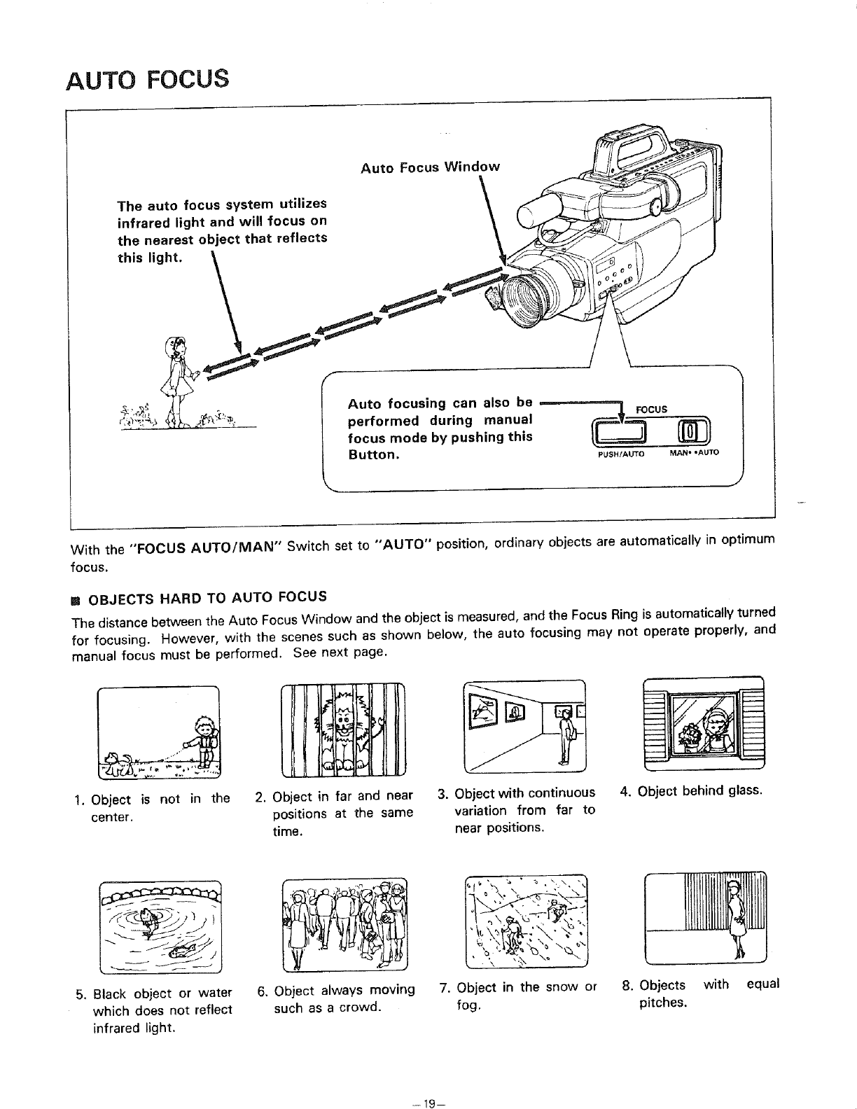
AUTO FOCUS
Auto Focus Window
The auto focus system utilizes \
infrared light and will focus on
the nearest object that reflects
this light. _
&,¢_ _j ° Auto focusing can also be
!"_J'_!_ 4,_tL_-,;_''_" performed during manual
focus mode by pushing this
Button. PUSH/AUTO MAN" .AUTO
With the "FOCUS AUTO/MAN" Switch set to "AUTO" position, ordinary objects are automatically in optimum
focus.
ROBJECTS HARD TO AUTO FOCUS
The distance between the Auto FocusWindow and the object is measured, and the Focus Ring is automatically turned
for focusing. However, with the scenes such as shown below, the auto focusing may not operate properly, and
manual focus must be performed. See next page.
1. Object is not in the
center.
2. Object in far and near
positions at the same
time.
3. Object with continuous
variation from far to
near positions.
4. Object behind glass.
5. Black object or water
which does not reflect
infrared light.
6. Object always moving
such as a crowd.
'\ _,_\_ •
/,
½'\ ,_ \
7. Object in the snow or
fog.
8. Objects with equal
pitches.
--19--
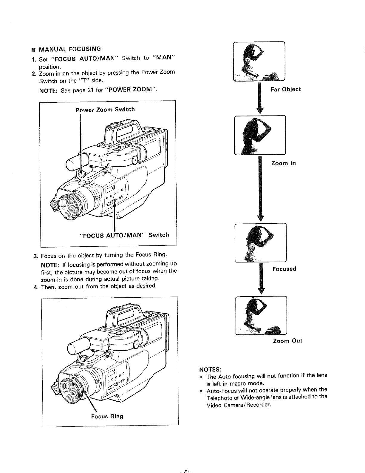
[] MANUAL FOCUSING
1. Set "FOCUS AUTO]MAN" Switch to "MAN"
position,
2. Zoom in on the object by pressing the Power Zoom
Switch on the "T" side.
NOTE: See page 21 for "POWER ZOOM".
Power Zoom Switch Far Object
Zoom In
"FOCUS AUTO/MAN" Switch
3. Focus on the object by turning the Focus Ring.
NOTE: If focusing is performed without zooming up
first, the picture may become out of focus when the
zoom-in is done during actual picture taking.
4. Then, zoom out from the object as desired. __ Focused
Focus Ring
Zoom Out
NOTES:
• The Auto focusing will not function if the lens
is left in macro mode.
e Auto-Focus will not operate properly when the
Telephoto orWide-angle lens is attached to the
Video Camera/Recorder.
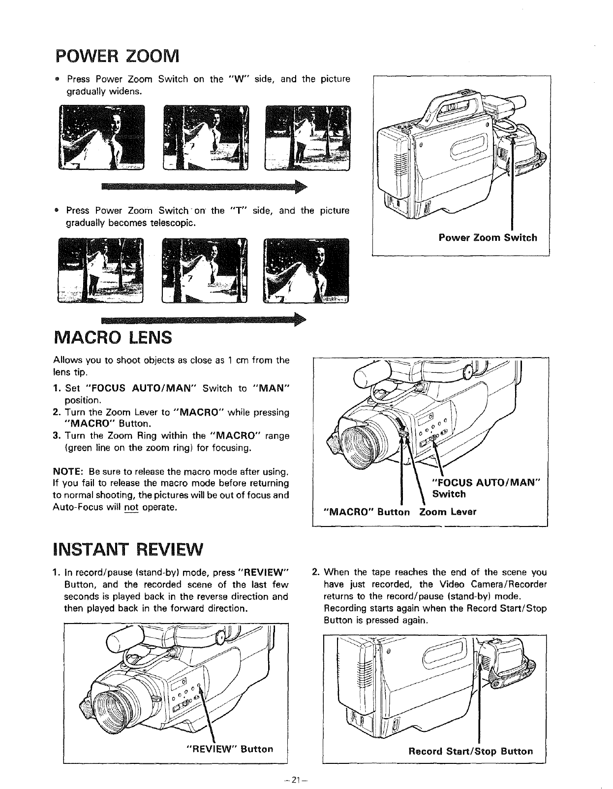
POWER ZOOM
® Press Power Zoom Switch on the "'W" side,
gradually widens.
and the picture
m__ ®
Press Power Zoom Switch on the "T'" side, and the picture
gradually becomes telescopic.
Power Zoom Switch
MACRO LENS
Allows you to shoot objects as close as 1 cm from the
lens tip.
I. Set "FOCUS AUTO/MAN" Switch to "MAN"
position.
2. Turn the Zoom Lever to "MACRO" while pressing
"MACRO" Button.
3. Turn the Zoom Ring within the "MACRO" range
(green line on the zoom ring) for focusing.
NOTE: Be sure to release the macro mode after using.
If you fail to release the macro mode before returning
to normal shooting, the pictures will be out of focus and
Auto-Focus will no__ttoperate. "MACRO" Button
"FOCUS AUTO/MAN"
Switch
Zoom Lever
iNSTANT REVIEW
1. In record/pause (stand-by) mode, press "REVIEW"
Button, and the recorded scene of the last few
seconds is played back in the reverse direction and
then played back in the forward direction.
2. When the tape reaches the end of the scene you
have just recorded, the Video Camera/Recorder
returns to the record/pause (stand-by) mode.
Recording starts again when the Record Start/Stop
Button is pressed again.
"REVIEW" Button Record Start/Stop Button
-21-
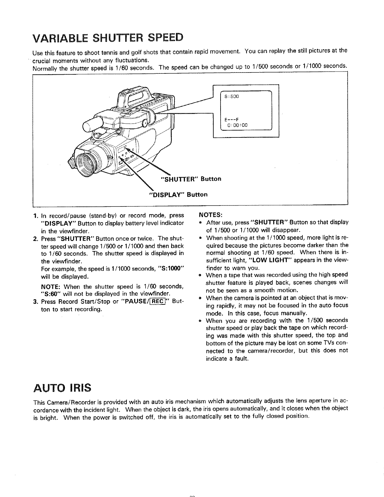
VARIABLE SHUTTER SPEED
Use this feature to shoot tennis and golf shots that contain rapid movement. You can replay the still pictures at the
crucial moments without any fluctuations.
Normally the shutter speed is 1/60 seconds. The speed can be changed up to 1/500 seconds or 1/1000 seconds.
S:500
E---F
0:00:O0
"SHUTTER" Button
"DISPLAY" Button
1. In record/pause (stand-by) or record mode, press
"DISPLAY" Button to display battery level indicator
in the viewfinder.
2. Press "SHUTTER" Button once or twice. The shut-
ter speed will change 1/500 or 1/1000 and then back
to 1/60 seconds. The shutter speed is displayed in
the viewfinder.
For example, the speed is 1/1000 seconds, "S:1000"
will be displayed.
NOTE: When the shutter speed is 1/60 seconds,
"S:60" will not be displayed in the viewfinder.
3. Press Record Start/Stop or "'PAUSE/[-R-E-_'" But-
ton to start recording.
NOTES:
o After use, press "SHUTTER" Button so that display
of 1/500 or 1/1000 will disappear.
•When shooting at the 1/1000 speed, more light is re-
quired because the pictures become darker than the
normal shooting at 1/60 speed. When there is in-
sufficient light, "LOW LIGHT" appears in the view-
finder to warn you.
o When a tape that was recorded using the high speed
shutter feature is played back, scenes changes will
not be seen as a smooth motion.
• When the camera is pointed at an object that is mov-
ing rapidly, it may not be focused in the auto focus
mode. In this case, focus manually.
o When you are recording with the 1/500 seconds
shutter speed or play back the tape on which record-
ing was made with this shutter speed, the top and
bottom of the picture may be lost on some TVs con-
nected to the camera/recorder, but this does not
indicate a fault,
AUTO IRiS
This Camera/Recorder is provided with an auto iris mechanism which automatically adjusts the lens aperture in ac-
cordance with the incident light. When the object is dark, the iris opens automatically, and it closes when the object
is bright. When the power is switched off, the iris is automatically set to the fully closed position.
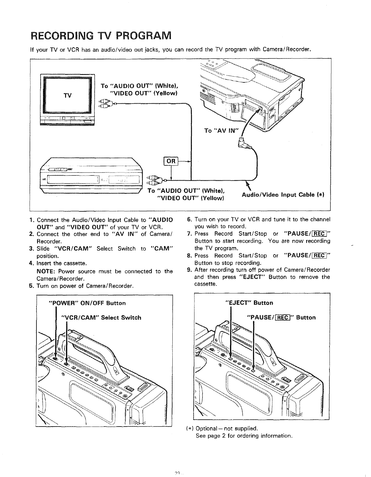
RECORDING TV PROGRAM
If your TV or VCR has an audio/video out jacks, you can record the TV program with Camera/Recorder.
TV
To "AUDIO OUT" (White).
"VIDEO OUT" (Yellow)
-_:':_-7 j To "AUDIO OUT" (White),
"VIDEO OUT" (Yellow) Audio/Video Input Cable (_)
1. Connect the Audio/Video Input Cable to "AUDIO
OUT" and "VIDEO OUT" of your TV or VCR.
2. Connect the other end to "AV IN" of Camera/
Recorder.
3, Slide "VCR/CAM'" Select Switch to "CAM"
position.
4. Insert the cassette.
NOTE: Power source must be connected to the
Camera/Recorder.
5. Turn on power of Camera/Recorder.
I "POWER" ON/OFF Button
"VCR/CAM" Select Switch
6. Turn on your TV or VCR and tune it to the channel
you wish to record.
7. Press Record Start/Stop or "'PAUSE/_"
Button to start recording. You are now recording
the TV program.
8. Press Record Start/Stop or "'PAUSE/[]_'"
Button to stop recording.
9. After recording turn off power of Camera/Recorder
and then press "'EJECT" Button to remove the
cassette.
(*) Optional-- not supplied.
See page 2 for ordering information.
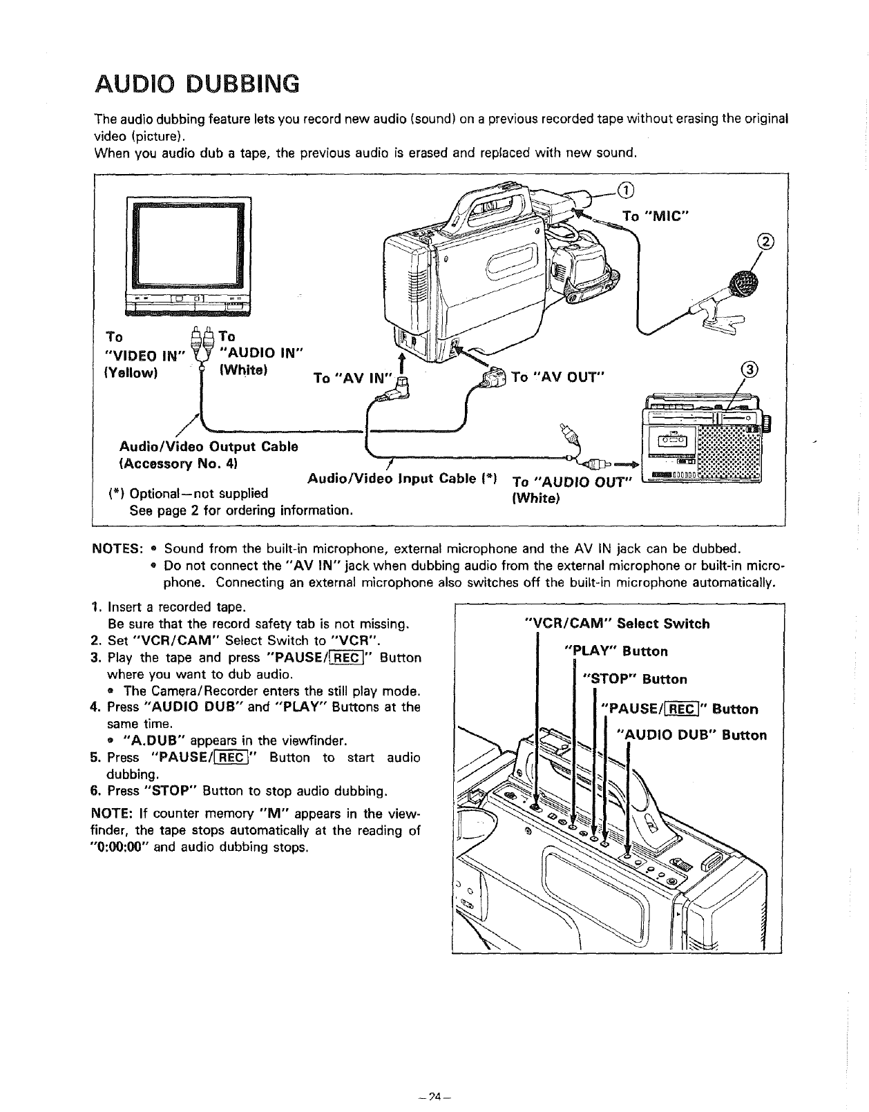
AUDIO DUBBING
The audio dubbing feature lets you record new audio (sound) on a previous recorded tape without erasing the original
video (picture).
When you audio dub a tape, the previous audio is erased and replaced with new sound.
To
"VIDEO IN"
(Yellow)
AUDIO IN"
(White) To "AV IN"
Audio/Video Input Cable 1_)
J
Audio/Video Output Cable
(Accessory No. 4)
(_) Optional--not supplied
See page 2for ordering information.
To "AV OUT"
To "AUDIO OUT"
(White)
"MIC"
®
@
NOTES: o Sound from the built-in microphone, external microphone and the AV IN jack can be dubbed.
• Do not connect the "'AV IN" jack when dubbing audio from the external microphone or built-in micro-
phone. Connecting an external microphone also switches off the built-in microphone automatically.
1. Insert arecorded tape.
Be sure that the record safety tab is not missing.
2. Set "VCR/CAM" Select Switch to "VCR".
3. Play the tape and press "'PAUSE/_'" Button
where you want to dub audio.
o The Camera/Recorder enters the still play mode.
4. Press "AUDIO DUB" and "'PLAY" Buttons at the
same time.
o "A.DUB" appears in the viewfinder.
5. Press "PAUSE/r-RE_" Button to start audio
dubbing.
6. Press "STOP" Button to stop audio dubbing.
NOTE: If counter memory "M" appears in the view-
finder, the tape stops automatically at the reading of
"'0:00:00" and audio dubbing stops.
"'VCR/CAM" Select Switch
"PLAY" Button
"STOP" Button
"PAUSE/[_]" Button
"AUDIO DUB" Button
-- ?4--
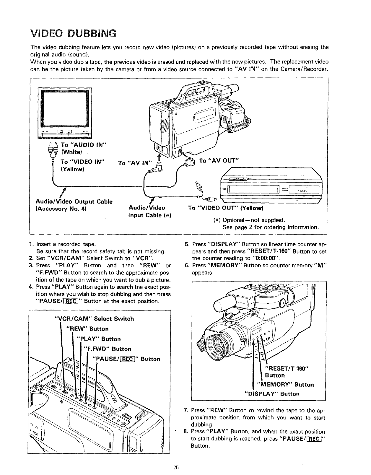
VIDEO DUBBING
The video dubbing feature lets you record new video (pictures) on a previously recorded tape without erasing the
original audio (sound).
When you video dub a tape, the previous video is erased and replaced with the new pictures, The replacement video
can be the picture taken by the camera or from a video source connected to "AV IN" on the Camera/Recorder.
D
.°°,,,..IWhite)
To "VIDEO IN"
{Yellow)
7
Audio/Video Output Cable
(Accessory No. 41
To "AV IN" /_ _To "AV OUT"
Audio/Video To "VIDEO OUT" (Yellow)
Input Cable (_} (*) Optional-- not supplied.
See page 2 for ordering information.
1. Insert a recorded tape.
Be sure that the record safety tab is not missing.
2. Set "'VCR/CAM'" Select Switch to "'VCR".
3. Press "PLAY" Button and then "REW" or
"'F.FWD" Button to search to the approximate pos-
ition of the tape on which you want to dub a picture.
4. Press "PLAY" Button again to search the exact pos-
ition where you wish to stop dubbing and then press
"'PAUSE/[-_" Button at the exact position,
"VCR/CAM" Select Switch
"REW" Button
"PLAY" Button
"F.FWD'" Button
"PAUSE/[J_" Button
5. Press "DISPLAY" Button so linear time counter ap-
pears and then press "RESET/T-160"" Button to set
the counter reading to "'0:00:00".
6. Press "MEMORY" Button so counter memory "M"
appears.
"RESET/T-160"
Button
"MEMORY" Button
"DISPLAY" Button
7. Press "REW" Button to rewind the tape to the ap-
proximate position from which you want to start
dubbing.
8. Press "PLAY" Button, and when the exact position
to start dubbing is reached, press "PAUSE/[-_"
Button.
- 25--
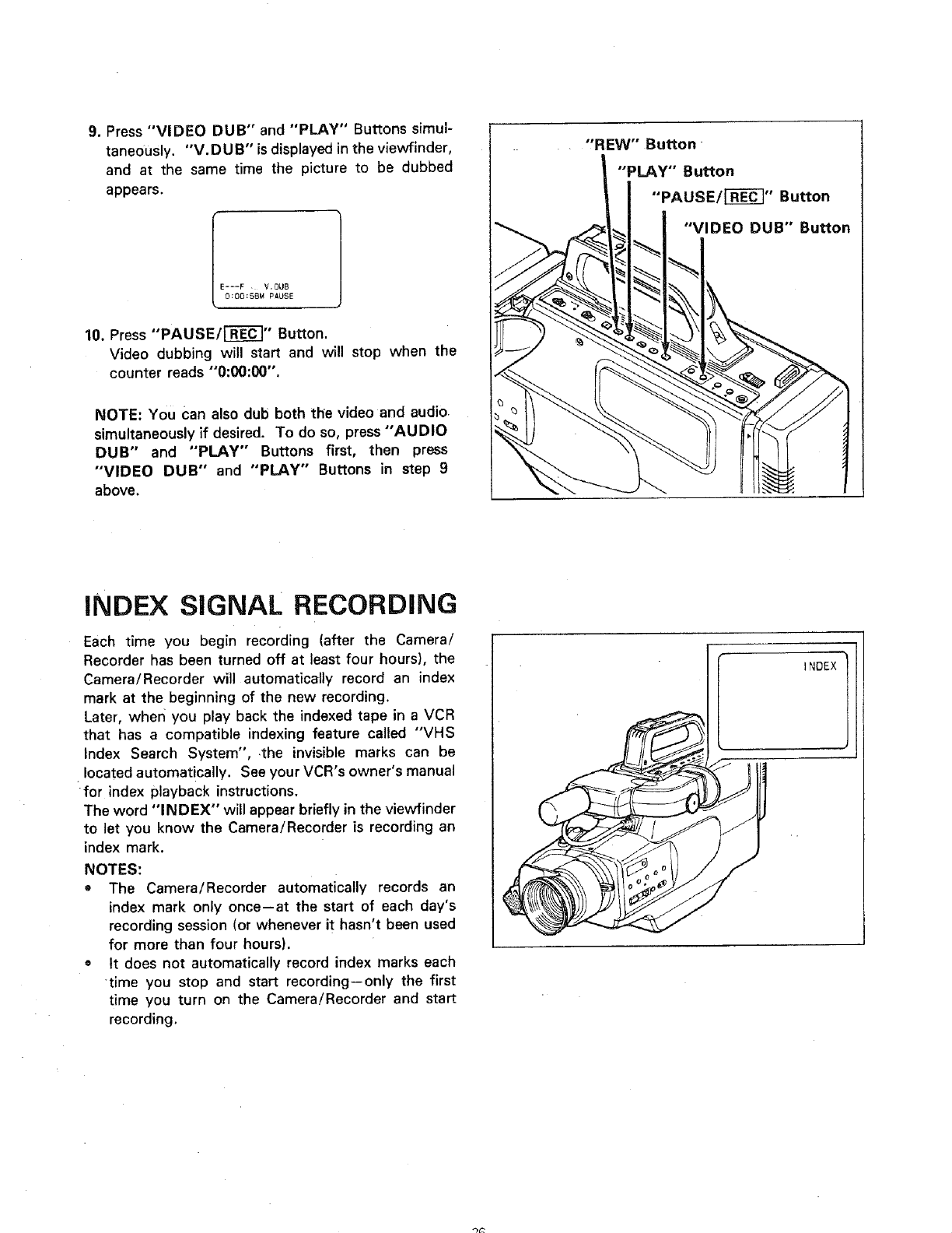
9. Press "VIDEO DUB" and "PLAY" Buttons simul-
taneously. "V.DUB" isdisplayed in the viewfinder,
and at the same time the picture to be dubbed
appears.
I---F V. DUB
O:OO:SSM PAUSE
10. Press "PAUSE/[]_" Button.
Video dubbing will start and will stop when the
counter reads "0:00:00".
NOTE: You Can also dub both the video and audio
simultaneously if desired. To do so, press "AUDIO
DUB" and "PLAY" Buttons first, then press
"VIDEO DUB" and "PLAY" Buttons in step 9
above.
INDEX SIGNAL RECORDING
Each time you begin recording (after the Camera/
Recorder has been turned off at least four hours), the
Camera/Recorder will automatically record an index
mark at the beginning of the new recording.
Later, wherl you play back the indexed tape in a VCR
that has acompatible indexing feature called "VHS
Index Search System", the invisible marks can be
located automatically. See your VCR's owner's manual
for index playback instructions.
The word "IN D EX" will appear briefly in the viewfinder
to let you know the Camera/Recorder is recording an
index mark.
NOTES:
•The Camera/Recorder automatically records an
index mark only once--at the start of each day's
recording session (or whenever it hasn't been used
for more than four hours).
•It does not automatically record index marks each
time you stop and start recording--only the first
time you turn on the Camera/Recorder and start
recording.
"REW" Button
"PLAY" Button
"PAUSE/i-_-_" Button
"VIDEO DUB" Button
INDEX
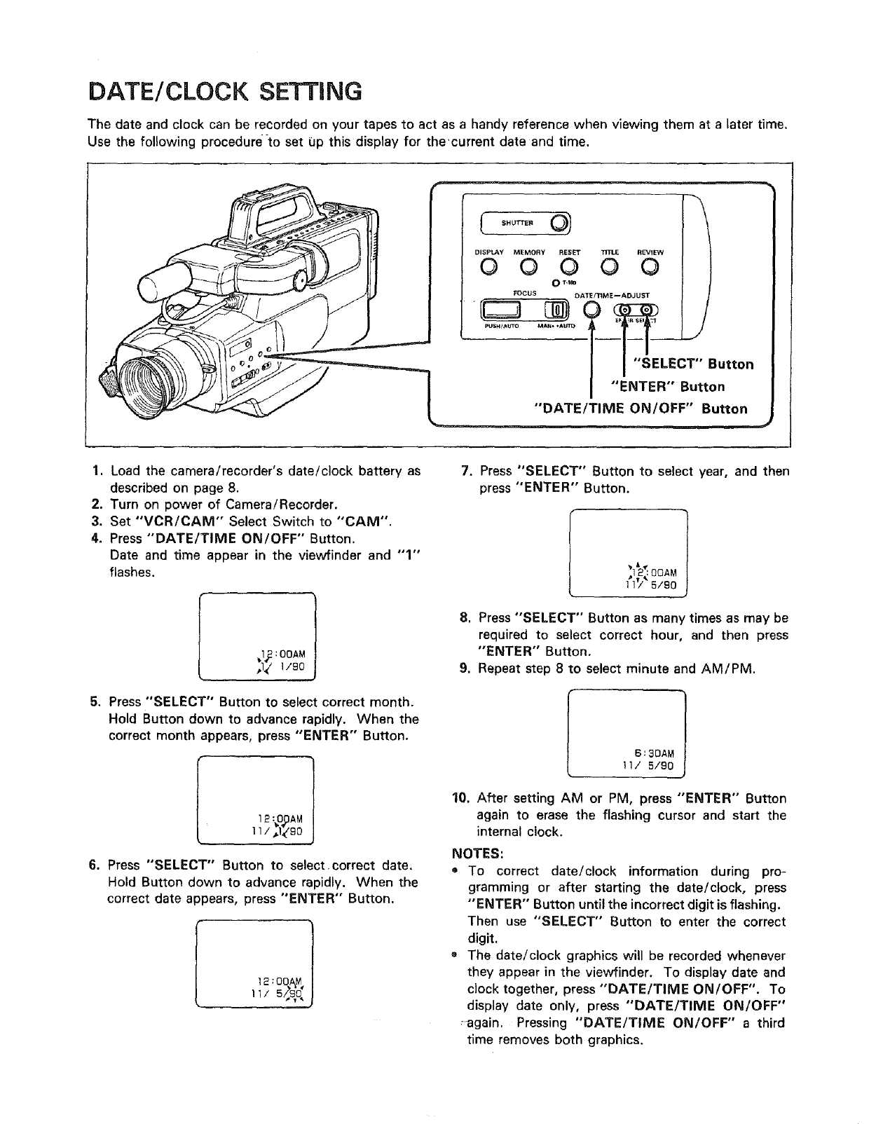
DATE/CLOCK SETTING
The date and clock can be recorded on your tapes to act as a handy reference when viewing them at a later time.
Use the following procedure to set 0p this display for the'current date and time.
Pu_._._o MA...Am --[--[--------L._
i"SELECT'°
Button
"ENTER" Button
"DATErTIME ON/OFF" Button
1. Load the camera/recorder's date/clock battery as
described on page 8.
2. Turn on power of Camera/Recorder.
3. Set "VCR/CAM" Select Switch to "'CAM".
4. Press "DATE/TIME ON/OFF" Button.
Date and time appear in the viewfinder and "1"
flashes.
_I_ :OOAM
,,I_/1190
5. Press "SELECT" Button to select correct month.
Hold Button down to advance rapidly. When the
correct month appears, press "ENTER" Button.
I 12 :_.O,_AM
1l /_I_/90
6. Press "SELECT" Button to select,correct date,
Hold Button down to advance rapidly. When the
correct date appears, press "ENTER" Button.
1
12:OOA_,I
11/5/.s, j
7. Press "SELECT" Button to select year, and then
press "ENTER" Button.
] 1'/ 5/9o
8. Press "SELECT" Button as many times as may be
required to select correct hour, and then press
"ENTER" Button.
9. Repeat step 8 to select minute and AM/PM.
6:3DAM
11/ 5/90
10. After setting AM or PM, press "ENTER" Button
again to erase the flashing cursor and start the
internal clock.
NOTES:
oTo correct date/clock information during pro-
gramming or after starting the date/clock, press
"ENTER" Button until the incorrect digit is flashing.
Then use "SELECT" Button to enter the correct
digit.
•The date/clock graphics will be recorded whenever
they appear in the viewfinder. To display date and
clock together, press "DATE/TIME ON/OFF". To
display date only, press "DATE/TIME ON/OFF"
:again. Pressing "DATE/TIME ON/OFF" a third
time removes both graphics.
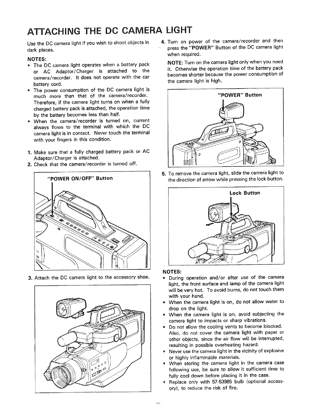
ATTACHING THE DC CAMERA UGHT
Use the DC camera light if you wish to shoot objects in
dark places.
NOTES:
o The DC camera light operates when a battery pack
or AC Adaptor/Charger is attached to the
camera/recorder. It does not operate with the car
battery cord.
® The power consumption of the DC camera light is
much more than that of the camera/recorder.
Therefore, if the camera light turns on when a fully
charged battery pack is attached, the operation time
by the battery becomes less than half.
o When the camera/recorder is turned on, current
always flows to the terminal with which the DC
camera light is in contact, Never touch the terminal
with your fingers in this condition.
1. Make sure that a fully charged battery pack or AC
Adaptor/Charger is attached.
2. Check that the camera/recorder is turned off.
"POWER ON/OFF" Button
4. Turn on power of the camera/recorder and then
press the "POWER '_'Button of the DCcamera light
when required.
NOTE: Turn on the camera light only when you need
it. Otherwise the operation time of the battery pack
becomes shorter because the power consumption of
the camera light is high.
"POWER" Button
Q
5. To remove the camera light, slide the camera light to
the direction of arrow while pressing the lock button.
Lock Button
3. Attach the DC camera light to the accessory shoe.
NOTES:
o During operation and/or after use of the camera
light, the front surface and lamp of the camera light
will be very hot. To avoid burns, do not touch them
with your hand.
o When the camera light is on, do not allow water to
drop on the light.
• When the camera light is on, avoid subjecting the
camera light to impacts or sharp vibrations.
e Do not allow the cooling vents to become blocked.
Also, do not cover the camera light with paper or
other objects, since the air flow will be interrupted,
resulting in possible overheating hazard.
e Never use the camera light in the vicinity of explosive
or highly inflammable materials.
• When storing the camera light in the camera case
following use, be sure to allow it sufficient time to
fully cool down before placing it in the case.
• Replace only with 57-53985 bulb (optional access-
ory), to reduce the risk of fire.
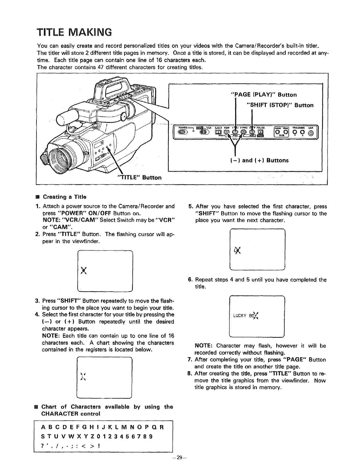
TITLE MAKING
You can easily create and record personalized titles on your videos with the Camera/Recorder's built-in titler.
The titler will store 2different title pages in memory. Once a title is stored, it can be displayed and recorded at any-
time. Each title page can contain one line of 16 characters each.
The character contains 47 different characters for creating titles.
"PAGE (PLAY)" Button
"SHIFT (STOP)" Button
-) and (+) Buttons
"TITLE" Button
[] Creating a Title
1. Attach a power source to the Camera/Recorder and
press "POWER" ON/OFF Button on.
NOTE: "VCR/CAM'" Select Switch may be "VCR"
or "CAM".
2. Press "TITLE" Button. The flashing cursor will ap-
pear in the viewfinder.
5. After you have selected the first character, press
"SHIFT" Button to move the flashing cursor to the
place you want the next character,
3. Press "SHIFT" Button repeatedly to move the flash-
ing cursor to the place you want to begin your title.
4. Select the first character for your title by pressing the
(--) or (+) Button repeatedly until the desired
character appears.
NOTE: Each title can contain up to one line of 16
characters each.'A chart showing the characters
contained in the registers is located below.
,L
6. Repeat steps 4 and 5 until you have completed the
title.
LUCKY B_Y:
NOTE: Character may flash, however it will be
recorded correctly without flashing.
7. After completing your title, press "PAGE" Button
and create the title on another title page.
8, After creating the title, press "TITLE" Button to re-
move the title graphics from the vievvfinder. Now
title graphics is stored in memory.
mChart of Characters available by using the
CHARACTER control
ABCDEFGHIJKLM NOPQR
STUVWXYZ0123456789
?'./,-;: <>!
-29-
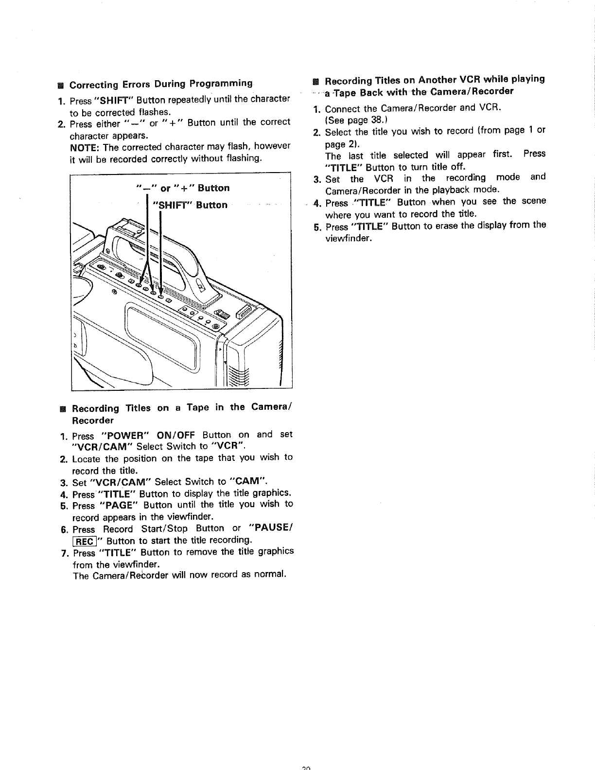
[] Correcting Errors During Programming
1, Press"SHIFT" Button repeatedlyuntil the Character
to be corrected flashes.
2. Press either "'--" or "+" Button until the correct
character appears.
NOTE: The corrected character may flash, however
it will be recorded correctly without flashing.
"'--'" or "' -F "' Button
I"'SHIFT" Button ......
[] Recording Titles on Another VCR while playing
.....a-Tape Back with the Camera/Recorder
1. Connect the Camera/Recorder and VCR.
(See page 38.)
2. Select the title you wish to record (from page !or
page 2).
The last title selected will appear first. Press
"TITLE" Button to turn title off.
3. Set the VCR in the recording mode and
Camera/Recorder in the playback mode,
4. Press ,"TITLE" Button when you see the scene
where you want to record the title,
5. Press "TITLE" Button to erase the displayfrom the
viewfinder.
mRecording Titles on a Tape in the Camera/
Recorder
1. Press "POWER" ON/OFF Button on and set
"VCR/CAM" Select Switch to "'VCR".
2. Locate the position on the tape that you wish to
record the title.
3. Set "VCR/CAM" Select Switch to "'CAM",
4. Press "TITLE" Button to display the title graphics,
5. Press "PAGE" Button until the title you wish to
record appears in the viewfinder.
6. Press Record Start/Stop Button or "PAUSE/
[_" Button to start the title recording.
7, Press "TITLE" Button to remove the title graphics
from the viewfinder.
The Camera/Recorder will now record as normal.
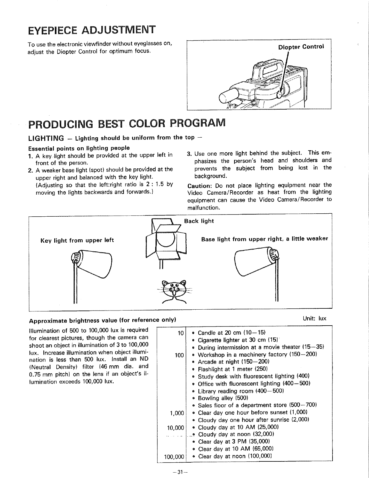
EYEPIECE ADJUSTMENT
To use the electronic viewfinder without eyeglasses on,
adjust the Diopter Control for optimum focus. Diopter Control
PRODUCING BEST COLOR PROGRAM
LIGHTING -Lighting should be uniform from the top --
Essential points on lighting people
1. A key light should be provided at the upper left in
front of the person.
2. Aweaker base light (spot) should be provided at the
upper right and balanced with the kev light.
(Adjusting so that the left:right ratio is 2 : 1.5 by
moving the lights backwards and forwards.)
Key light from upper left
3. Use one more light behind the subject. This em-
phasizes the person's head and shoulders and
prevents the subject from being lost in the
background.
Caution: Do not place lighting equipment near the
Video Camera/Recorder as heat from the lighting
equipment can cause the Video Camera/Recorder to
malfunction.
_, _Back light
Base light from upper right, a little weaker
Approximate brightness value (for reference only)
Illumination of 500 to 100,000 lux is required
for clearest pictures, though the camera can
shoot an object in illumination of 3 to 100,000
lux. Increase illumination when object illumi-
nation is less than 500 lux. Install an ND
(Neutral Density) filter (46mm dia. and
0.75 mm pitch) on the lens if an object's il-
lumination exceeds 100,000 lux.
10
100
1,000
I0,000
100,000
Unit: lux
• Candle at 20 cm (10--15)
= Cigarette lighter at 30 cm (15)
•During intermission at a movie theater (15--35)
= Workshop in a machinery factory (150--200)
• Arcade at night (150--200)
•Flashlight at 1meter (250)
•Study desk with fluorescent lighting (400)
•Office with fluorescent lighting (400--500)
Library reading room (400--500)
® Bowling alley (500)
• Sales floor of a department store (500-700)
• Clear day one hour before sunset (1,000)
Cloudy day one hour after sunrise (2,000)
• Cloudy day at 10 AM (25,000)
,.._ Cloudy day at noon (32,000)
o Clear day at 3 PM (35,000)
• Clear day at 10 AM (65,000)
• Clear day at noon (100,000)
--31 --
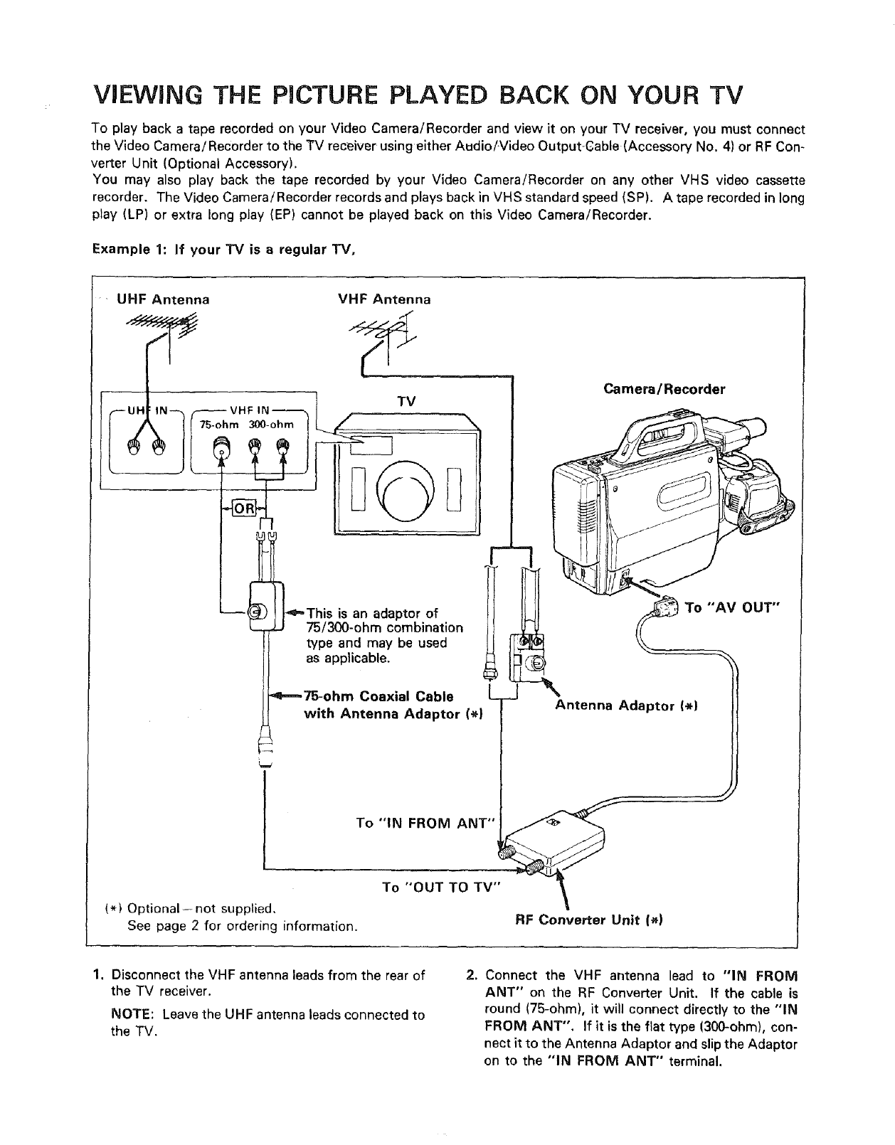
VIEWING THE PICTURE PLAYED BACK ON YOUR TV
To play back a tape recorded on your Video Camera/Recorder and view it on your TV receiver, you must connect
the Video Camera!Recorder to the TV receiver using either Audio/Video OutputCable (Accessory No. 4) or RF Con-
verter Unit (Optional Accessory).
You may also play back the tape recorded by your Video Camera/Recorder on any other VHS video cassette
recorder. The Video Camera/Recorder records and plays back in VHS standard speed (SP). A tape recorded in long
play (LP) or extra long play (EP) cannot be played back on this Video Camera/Recorder.
Example 1: If your TV is a regular TV,
• UHF Antenna VHF Antenna
TV Camera/Recorder
_==This is an adaptor of To "'AV OUT"
75/300-ohm combination
!l type and may be used
]as applicable. ,_
I Coa, alCable
with Antenna Adaptor (_} Antenna Adaptor (_)
/
To "IN FROM ANT"
To "OUT TO TV"
(*) Optional--not supplied,
See page 2 for ordering information. RF Converter Unit (_)
1. Disconnect the VHF antenna leads from the rear of
the "IV receiver.
NOTE: Leave the UHF antenna leads connected to
the "IV.
2. Connect the VHF antenna lead to "IN FROM
ANT" on the RF Converter Unit. If the cable is
round (75-ohm), it will connect directly to the "IN
FROM ANT". If it is the flat type (300-ohm), con-
nect it to the Antenna Adaptor and slip the Adaptor
on to the "'IN FROM ANT" terminal.
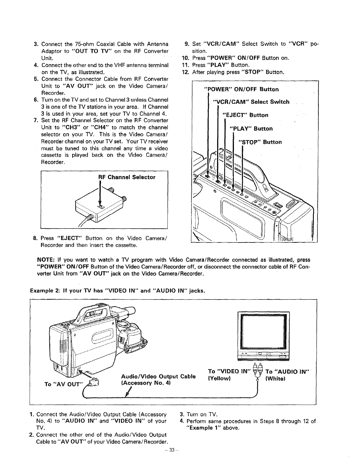
3. Connectthe75-ohmCoaxialCablewith Antenna
Adaptorto "OUT TOTV'" on the RFConverter
Unit.
4. ConnecttheotherendtotheVHFantennaterminal
ontheTV, as illustrated.
5, Connect the Connector Cable from RF Converter
Unit to "AV OUT" jack on the Video Camera/
Recorder.
6, Turn on the TV and set to Channel 3 unless Channel
3 is one of the TV stations in your area. If Channel
3 is used in your area, set your TV to Channel 4.
7. Set the RF Channel Selector on the RF Converter
Unit to "CH3'" or "'CH4" to match the channel
selector on your TV. This is the Video Camera/
Recorder channel on your TV set. Your TV receiver
must be tuned to this channel any time a video
cassette is played back on the Video Camera/
Recorder.
RF Channel Selector
8. Press "EJECT" Button on the Video Camera/
Recorder and then insert the cassette.
9. Set "VCR/CAiVI" Select Switch to "VCR" po-
sition.
10, Press "'POWER" ON/OFF Button on.
11. Press "PLAY" Button.
12. After playing press "STOP" Button,
"POWER" ON/OFF Button
"VCR/CAM" Select Switch
"EJECT" Button
"PLAY" Button
"STOP" Button
NOTE: if you want to watch a TV program with Video Camera/Recorder connected as illustrated, press
"POWER" ON/OFF Button of the Video Camera/Recorder off, or disconnect the connector cable of RF Con-
verter Unit from "AV OUT" jack on the Video Camera/Recorder.
Example 2: If your "IV has "VIDEO IN" and "AUDIO IN" jacks,
To "AV OUT"
Audio/Video Output Cable
(Accessory No. 4)
/
M
To "VIDEO IN" _ To "AUDIO IN"
(Yellow) _j_ (White)
1. Connect the Audio!Video Output Cable (Accessory 3. Turn on TV.
No, 4) to "AUDIO IN" and "VIDEO IN" of your 4. Perform same procedures in Steps 8 through 12 of
TV. "Example 1" above.
2. Connect the other end of the Audio/Video Output
Cable to "AV OUT" of your Video Camera/Recorder.
- 33
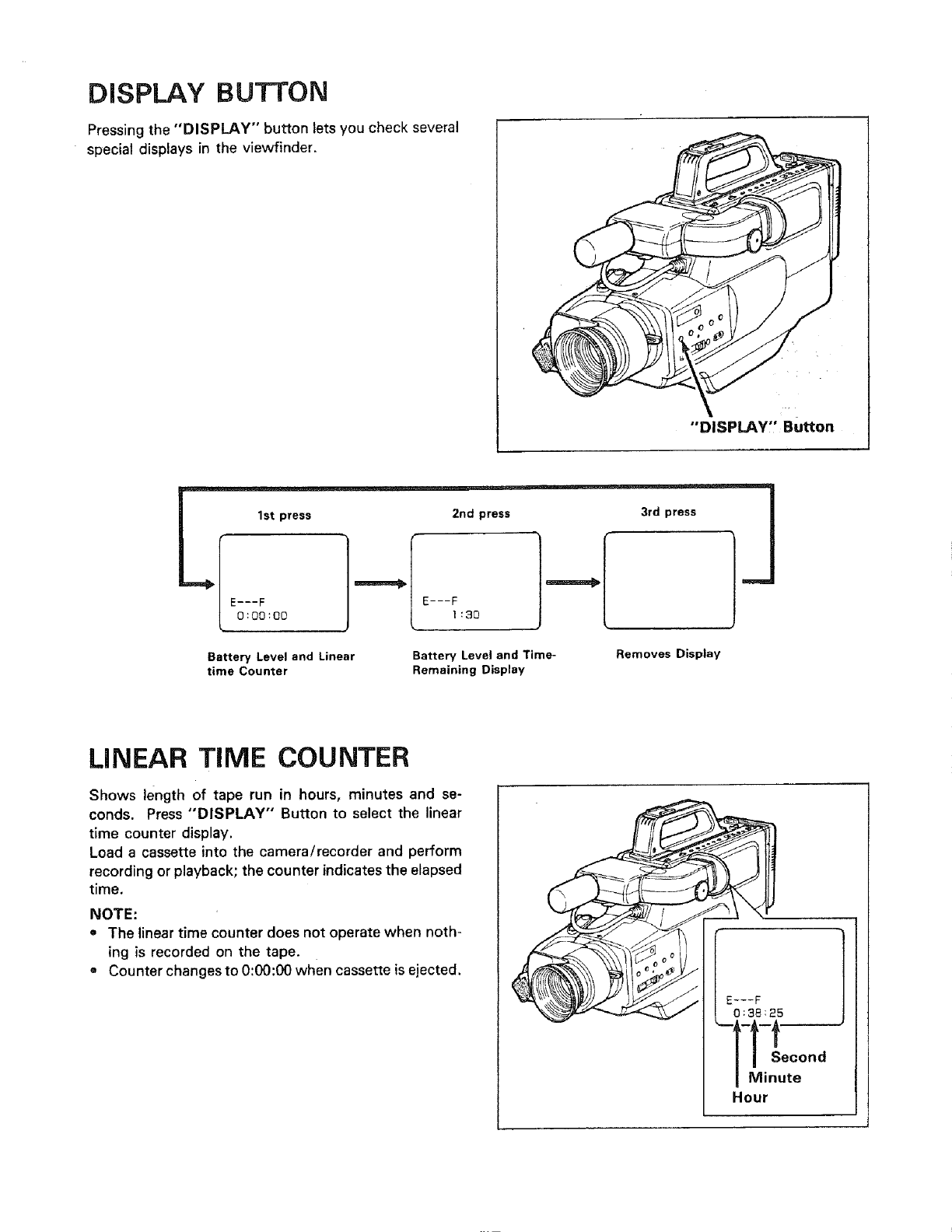
DISPLAY BUTTON
Pressing the "DISPLAY" button lets you check several
special displays in the viewfinder.
"DISPLAY,' Button
,- -2nd press ....
E---F E---F
0:00:00 1:30
Battery Level and Linear
time Counter Battery Level and Time-
Remaining Display
3rd press
Removes Display
LINEAR TiME COUNTER
Shows length of tape run in hours, minutes and se-
conds. Press "DISPLAY" Button to select the linear
time counter display.
Load a cassette into the camera/recorder and perform
recording or playback; the counter indicates the elapsed
time.
NOTE:
e The linear time counter does not operate when noth-
ing is recorded on the tape.
t Counter changes to 0:00:00 when cassette isejected.
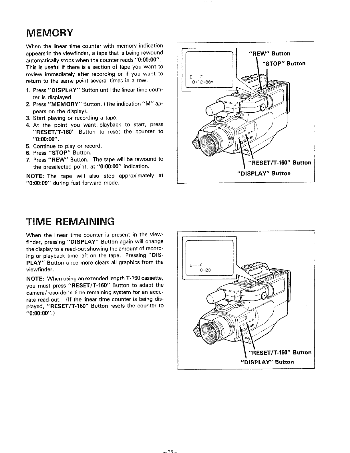
MEMORY
When the linear time counter with memory indication
appearsin the viewfinder, a tape that is being rewound
automatically stops when the counter reads "0:00:00".
This is useful if there is a section of tape you want to
review immediately after recording or if you want to
return to the same point several times in a row.
1. Press "DISPLAY" Button until the linear time coun-
ter is displayed.
2. Press "MEMORY" Button. (The indication "M" ap-
pears on the display).
3. Start playing or recording a tape.
4. At the point you want playback to start, press
"'RESET/T-160'" Button to reset the counter to
"0:00:00".
5. Continue to play or record.
6. Press "STOP" Button.
7. Press "REW" Button. The tape will be rewound to
the preselected point, at "0:00:00" indication.
NOTE: The tape will also stop approximately at
"0:00:00" during fast forward mode.
E---F
0:]2:86M
"'REW" Button
"STOP" Button
"'RESET/T-160" Button
"DISPLAY" Button
TIME REMAiNiNG
When the linear time counter is present in the view-
finder, pressing "DISPLAY" Button again will change
the display to a read-out showing the amount of record-
ing or playback time left on the tape. Pressing "DIS-
PLAY" Button once more clears all graphics from the
viewfinder.
NOTE: When using an extended length T-160 cassette,
you must press "RESET/T-160"" Button to adapt the
camera/recorder's time remaining system for an accu-
rate read-out. (If the linear time counter is being dis-
played, "RESET/T-160"" Button resets the counter to
"0:O0:00".)
"'RESET/T-160" Button
"DISPLAY" Button
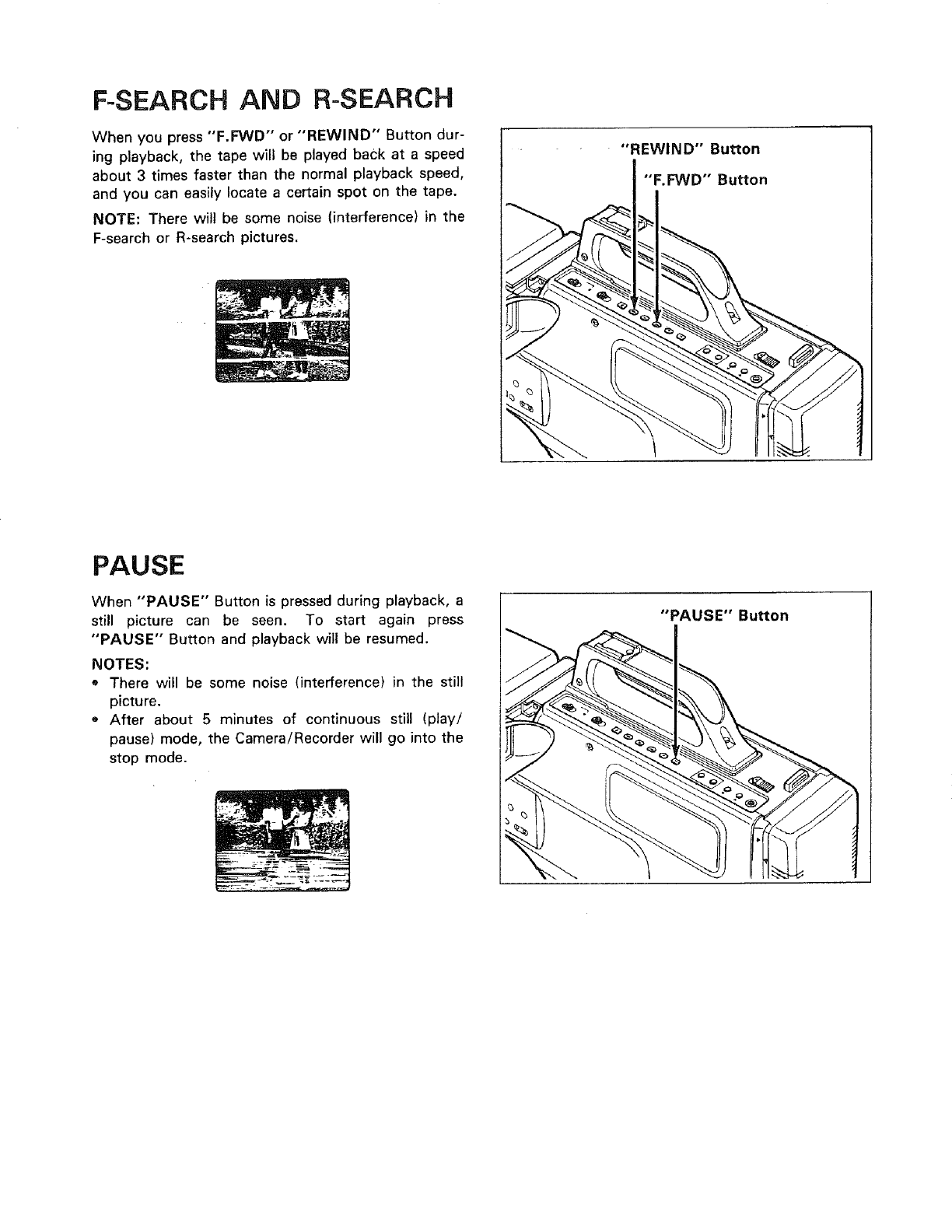
F-SEARCH AND R-SEARCH
When you press "F.FWD" or "REWIND" Button dur-
ing playback, the tape will be played back at a speed
about 3 times faster than the normal playback speed,
and you can easily locate a certain spot on the tape.
NOTE: There will be some noise (interference) in the
F-search or R-search pictures.
"REWIND" Button
"F.FWD'" Button
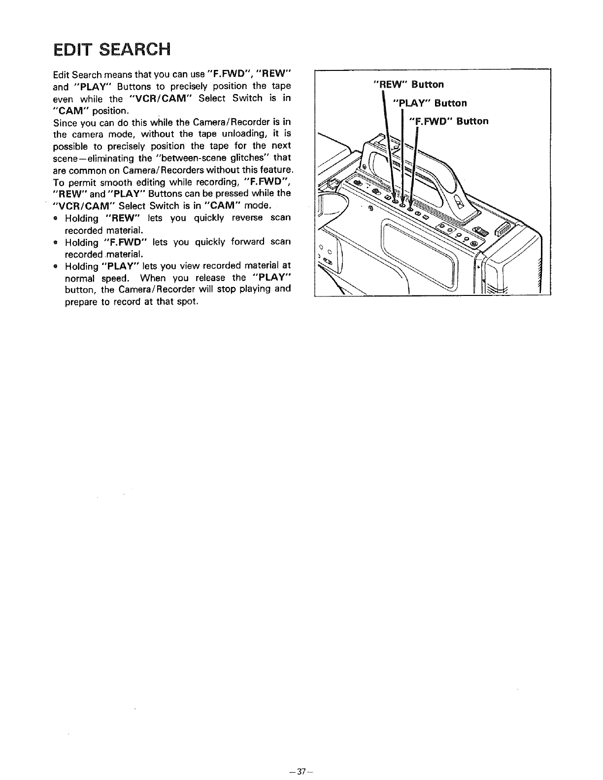
PAUSE
When "'PAUSE" Button is pressed during playback, a
still picture can be seen. To start again press
"PAUSE" Button and playback will be resumed.
NOTES:
oThere will be some noise (interference) in the still
picture.
•After about 5 minutes of continuous still (play/
pause) mode, the Camera/Recorder will go into the
stop mode.
I"PAUSE"Button
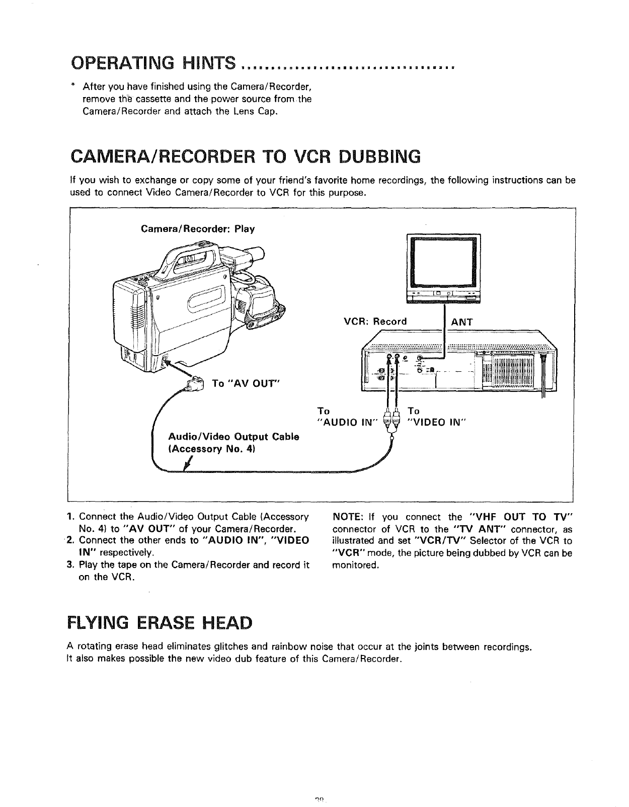
EDiT SEARCH
Edit Search means that you can use "F.FWD", "REW"
and "PLAY" Buttons to precisely position the tape
even while the "'VCR/GAM" Select Switch is in
"CAM" position.
Since you can do this while the Camera/Recorder is in
the camera mode, without the tape unloading, it is
possible to precisely position the tape for the next
scene--eliminating the "between-scene glitches" that
are common on Camera/Recorders without this feature.
To permit smooth editing while recording, "'F.FWD",
"REW" and "PLAY" Buttons can be pressed while the
"'VCR/CAM" Select Switch is in "CAM" mode.
®Holding "REW" lets you quickly reverse scan
recorded material.
=Holding "F.FWD" lets you quickly forward scan
recorded material.
oHolding "PLAY" lets you view recorded material at
normal speed. When you release the "PLAY"
button, the Camera/Recorder will stop playing and
prepare to record at that spot.
1"REW" Button
"PLAY" Button
"'F.FWD" Button
-- 37 -
OPERATING HINTS ....................................
After you have finished using the Camera/Recorder,
remove tht_ cassette and the power source from the
Camera!Recorder and attach the Lens Cap.
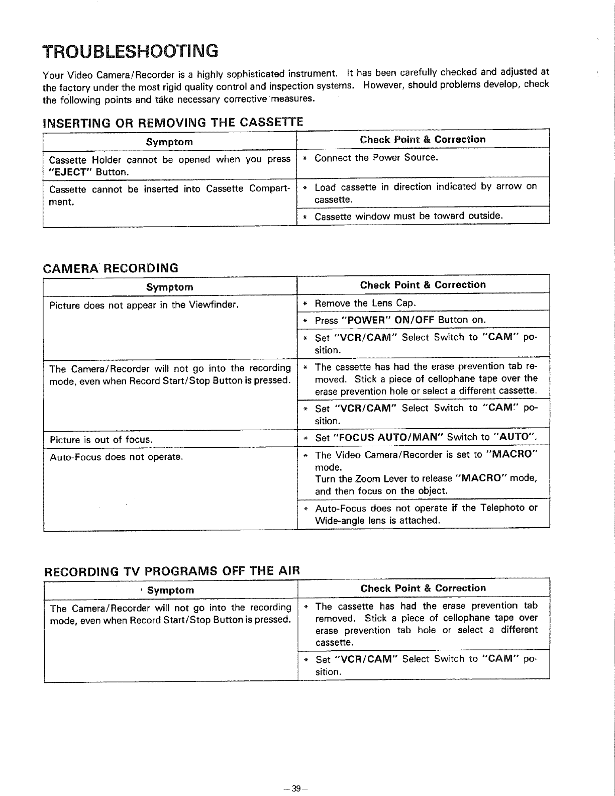
CAMERA/RECORDER TO VCR DUBBING
If you wish to exchange or copy some of your friend's favorite home recordings, the following instructions can be
used to connect Video Camera/Recorder to VCR for this purpose.
Camera/Recorder: Play
VCR: Record ANT
//_ To "AV OUT'" 4_U O I O
I Audio/Video Output Cable
To
"VIDEO IN"
1. Connect the Audio/Video Output Cable (Accessory
No. 4) to "'AV OUT" of your Camera/Recorder.
2. Connect the other ends to "AUDIO IN", "VIDEO
IN" respectively.
3. Play the tape on the Camera/Recorder and record it
on the VCR.
NOTE: If you connect the "'VHF OUT TO "IV'"
connector of VCR to the '"rv ANT" connector, as
illustrated and set "VCR/TV'" Selector of the VCR to
"VGR'" mode, the picture being dubbed by VCR can be
monitored.
FLYING ERASE HEAD
Arotating erase head eliminates glitches and rainbow noise that occur at the joints between recordings.
It also makes possible the new video dub feature of this Camera/Recorder.
TROUBLESHOOTUNG
Your Video Camera/Recorder is a highly sophisticated instrument. It has been carefully checked and adjusted at
the factory under the most rigid quality control and inspection systems. However, should problems develop, check
the following points and take necessary corrective measures.
INSERTING OR REMOVING THE CASSETTE
Symptom
Cassette Holder cannot be opened when you press
"EJECT" Button.
Cassette cannot be inserted into Cassette Compart-
ment.
Check Point & Correction
* Connect the Power Source.
CAMERA RECORDING
Symptom
Picture does not appear in the Viewfinder.
Load cassette in direction indicated by arrow on
cassette.
Cassette window must be toward outside.
The Camera/Recorder will not go into the recording
mode, even when Record Start/Stop Button is pressed.
$$
Picture is out of focus.
Auto-Focus does not operate.
RECORDING TV PROGRAMS OFF THE AIR
Check Point & Correction
Check Point & Correction
Remove the Lens Cap.
Press "POWER" ON/OFF Button on.
Set "VCR/CAM" Select Switch to "CAM" po-
sition.
The cassette has had the erase prevention tab re-
moved. Stick a piece of cellophane tape over the
erase prevention hole or select a different cassette.
Set -VCR/CAM" Select Switch to "CAM_' po-
sition.
Set "FOCUS AUTO/MAN" Switch to "'AUTO".
The Video Camera/Recorder is set to "MACRO"
mode.
Turn the Zoom Lever to release "MACRO" mode,
and then focus on the object.
Auto-Focus does not operate if the Telephoto or
Wide-angle lens is attached.
,Symptom
The Camera/Recorder will not go into the recording
mode, even when Record Start/Stop Button is pressed.
The cassette has had the erase prevention tab
removed. Stick apiece of cellophane tape over
erase prevention tab hole or select a different
cassette.
Set "'VCR/CAM'" Select Switch to "CAM" po-
sition.
- 39
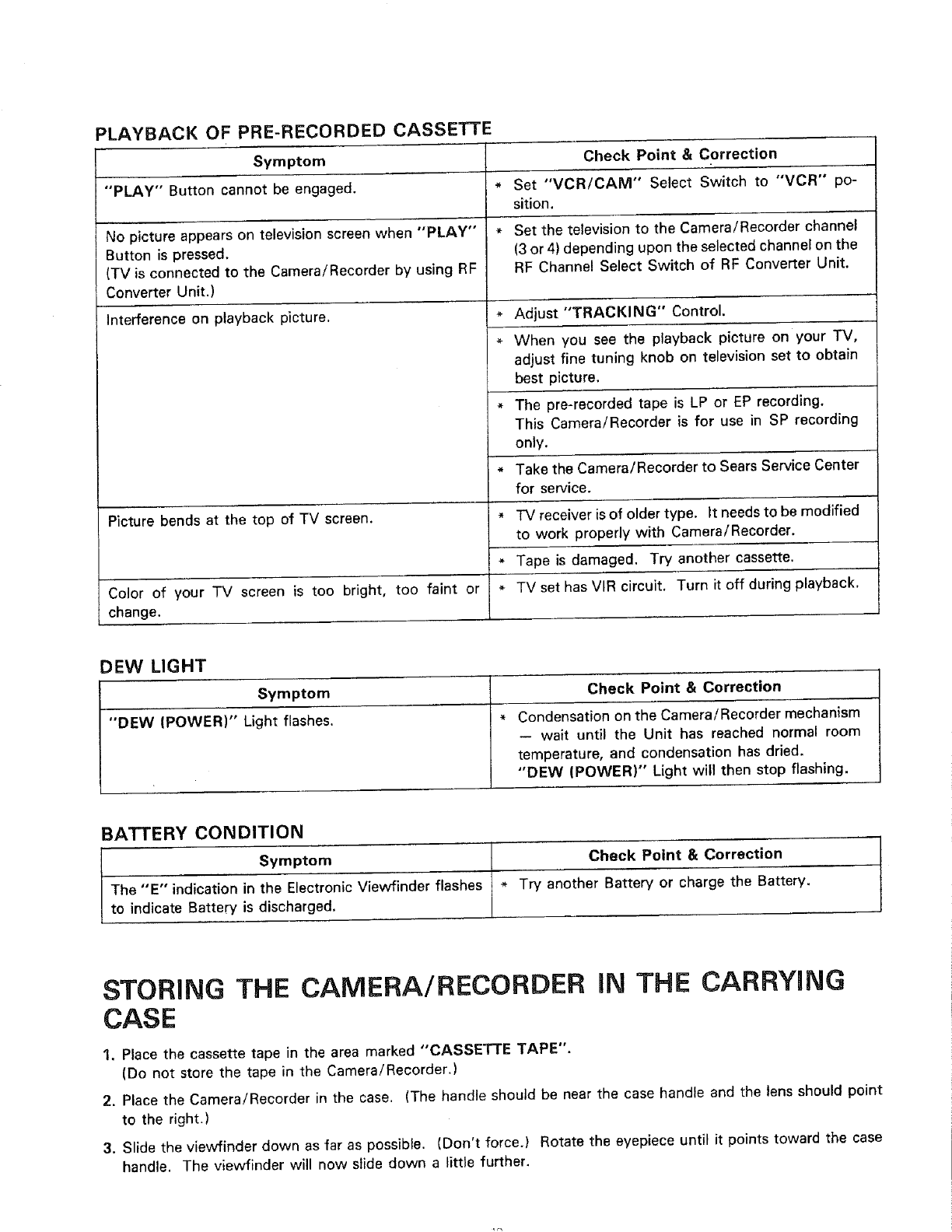
PLAYBACK OF PRE-RECORDED CASSETTE
Symptom Check Point &Correction
"PLAY" Button cannot be engaged. *Set "VCR/CAM" Select Switch to "VCR" po-
sition.
No picture appears on television screen when "PLAY" * Set the television to the Camera/Recorder channel
Button is pressed. (3 or 4) depending upon the selected channel on the
(TV is connected to the Camera/Recorder by using RF RF Channel Select Switch of RF Converter Unit.
Converter Unit.)
Interference on playback picture.
Picture bends at the top of TV screen.
* Adjust "TRACKING" Control.
When you see the playback picture on your "IV,
adjust fine tuning knob on television set to obtain
best picture.
* The pre-recorded tape is LP or EP recording.
This Camera/Recorder is for use in SP recording
only.
* Take the Camera/Recorder to Sears Service Center
for service.
Color of your TV screen is too bright, too faint or *
change.
DEW LIGHT
Symptom Check Point & Correction
"DEW (POWER)" Light flashes. * Condensation on the Camera/Recorder mechanism
-- wait until the Unit has reached normal room
temperature, and condensation has dried.
"DEW (POWER)" Light will then stop flashing.
BATTERY CONDITION
Symptom Check Point & Correction
The "E" indication in the ElectronicViewfinder flashes * Try another Battery or charge the Battery.
to indicate Battery is discharged.
TV receiver is of older type. it needs to be modified
to work properly with Camera/Recorder,
Tape is damaged, Try another cassette.
TV set has VIR circuit. Turn it off during playback.
STORING THE CAMERA/RECORDER IN THE CARRYING
CASE
1, Place the cassette tape in the area marked "CASSE'rI'E TAPE".
(Do not store the tape in the Camera/Recorder.)
2. Place the Camera/Recorder in the case. (The handle should be near the case handle and the lens should point
to the right.)
3. Slide the viewfinder down as far as possible. (Don't force,) Rotate the eyepiece until it points toward the case
handle. The viewfinder will now slide down a little further.
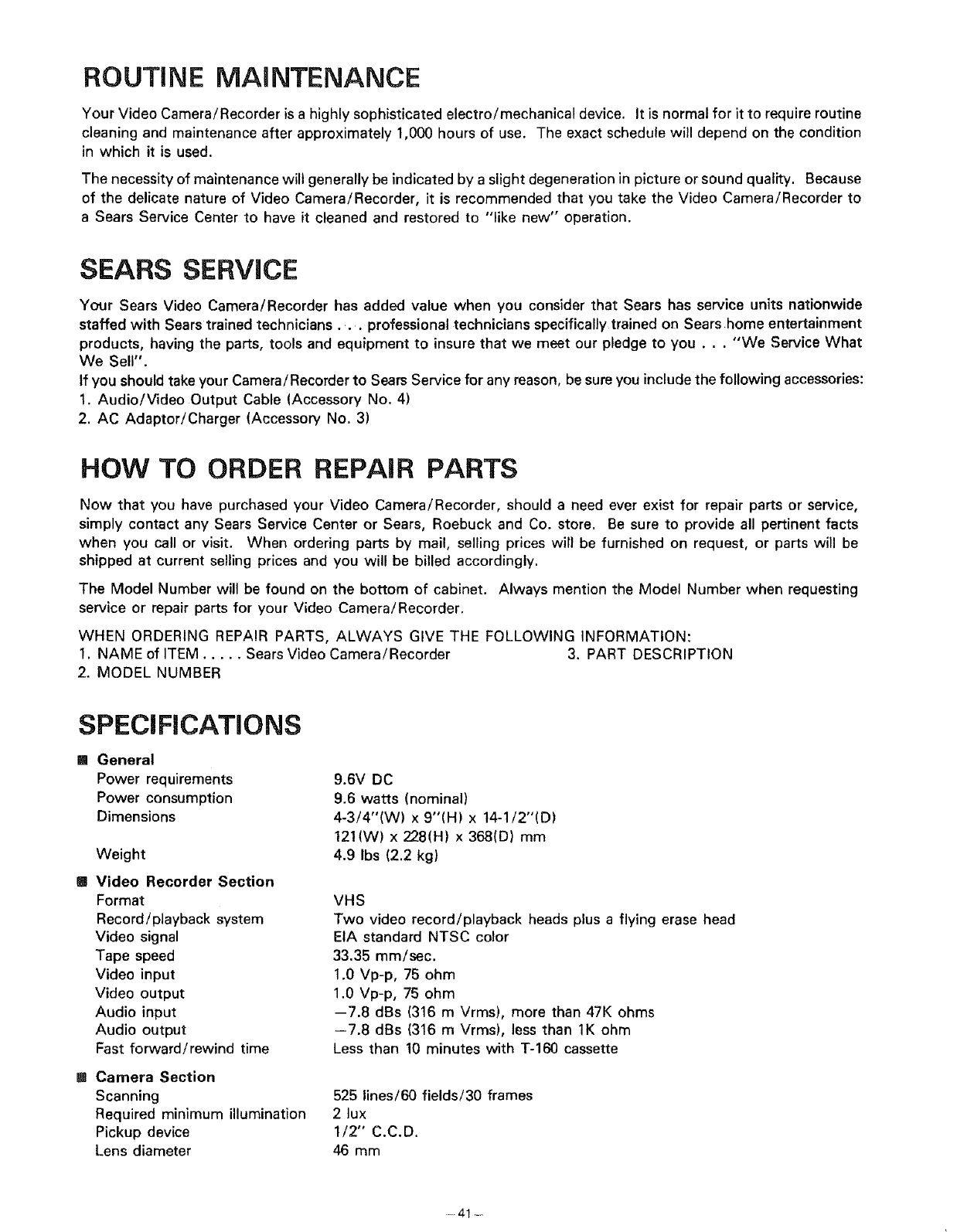
ROUTINE MAINTENANCE
Your Video Camera/Recorder is a highly sophisticated electro/mechanical device. It is normal for it to require routine
cleaning and maintenance after approximately 1,000 hours of use. The exact schedule will depend on the condition
in which it is used.
The necessity of maintenance will generally be indicated by aslight degeneration in picture or sound quality. Because
of the delicate nature of Video Camera/Recorder, it is recommended that you take the Video Camera/Recorder to
a Sears Service Center to have it cleaned and restored to "like new" operation.
SEARS SERVICE
Your Sears Video Camera/Recorder has added value when you consider that Sears has service units nationwide
staffed with Sears trained technicians ... professional technicians specifically trained on Sears.home entertainment
products, having the parts, tools and equipment to insure that we meet our pledge to you... "We Service What
We Sell".
If you should take your Camera/Recorder to Sears Service for any reason, be sure you include the following accessories:
1. Audio/Video Output Cable (Accessory No. 4)
2. AC Adaptor/Charger (Accessory No. 3)
HOW TO ORDER REPAIR PARTS
Now that you have purchased your Video Camera/Recorder, should a need ever exist for repair parts or service,
simply contact any Sears Service Center or Sears, Roebuck and Co. store. Be sure to provide all pertinent facts
when you call or visit. When ordering parts by mail, selling prices will be furnished on request, or parts will be
shipped at current selling prices and you will be billed accordingly.
The Model Number will be found on the bottom of cabinet. Always mention the Model Number when requesting
service or repair parts for your Video Camera/Recorder.
WHEN ORDERING REPAIR PARTS, ALWAYS GIVE THE FOLLOWING INFORMATION:
1. NAME of ITEM ..... Sears Video Camera/Recorder 3. PART DESCRIPTION
2. MODEL NUMBER
SPECIFICATIONS
[] General
Power requirements
Power consumption
Dimensions
Weight
[] Video Recorder Section
Format
Record/playback system
Video signal
Tape speed
Video input
Video output
Audio input
Audio output
Fast forward/rewind time
[] Camera Section
Scanning
Required minimum illumination
Pickup device
Lens diameter
9.6V DC
9.6 watts (nominal)
4-3/4"(W) x 9"(H) x 14-1/2"(D)
121(W) x 228(H) x 368(D) mm
4.9 Ibs (2.2 kg)
VHS
Two video record/playback heads plus a flying erase head
EIA standard NTSC color
33.35 mm/sec.
1.0 Vp-p, 75 ohm
1.0 Vp-p, 75 ohm
--7.8 dBs (316 m Vrms), more than 47K ohms
--7.8 dBs (316 m Vrms), less than 1K ohm
Less than 10 minutes with T-160 cassette
525 lines/60 fields/30 frames
2lux
1/2" C.C.D.
46 mm
-41 -
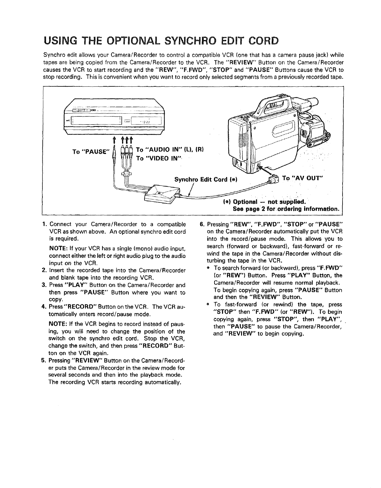
USING THE OPTIONAL SYNCHRO EDmTCORD
Synchro edit allows your Camera/Recorder to control a compatible VCR (one that has a camera pause jack) while
tapes are being copied from the Camera/Recorder to the VCR. The "REVIEW" Button on the Camera/Recorder
causes the VCR to start recording and the "'REW", "F.FWD", "STOP" and "PAUSE" Buttons cause the VCR to
stop recording. This is convenient when you want to record only selected segments from a previously recorded tape.
To "PAUSE"
f fft
To "AUDIO IN" (L), {R)
To "VIDEO IN "'_
Synchro Edit Cord (*) To ,'AV OUT"
I*) Optional not supplied.
See page'2 for ordering information.
1. Connect your Camera/Recorder to a compatible
VCR as shown above. An optional synchro edit cord
is required.
NOTE: If your VCR has a single (mono) audio input,
connect either the left or right audio plug to the audio
input on the VCR.
2. Insert the recorded tape into the Camera/Recorder
and blank tape into the recording VCR.
3. Press "PLAY" Button on the Camera/Recorder and
then press "PAUSE" Button where you want to
copy.
4. Press"RECORD" Button on the VCR. The VCR au-
tomatically enters record/pause mode.
NOTE: If the VCR begins to record instead of paus-
ing, you will need to change the position of the
switch on the synchro edit cord. Stop the VCR,
change the switch, and then press "RECORD" But-
ton on the VCR again.
5. Pressing "REVIEW" Button on the Camera/Record-
er puts the Camera/Recorder in the review mode for
several seconds and then into the playback mode.
The recording VCR starts recording automatically.
6. Pressing "'REW", "F.FWD", "STOP" or "PAUSE'"
on the Camera/Recorder automatically put the VCR
into the record/pause mode. This allows you to
search (forward or backward), fast-forward or re-
wind the tape in the Camera/Recorder without dis-
turbing the tape in the VCR.
OTo search forward (or backward), press "F.FWD"
(or "REW") Button. Press "PLAY" Button, the
Camera/Recorder will resume normal playback.
To begin copying again, press "PAUSE" Button
and then the "REVIEW" Button.
To fast-forward (or rewind) the tape, press
"STOP" then "F.FWD'" (or "REW"I. To begin
copying again, press "STOP", then "PLAY",
then "PAUSE" to pause the Camera/Recorder,
and "REVIEW" to begin copying.
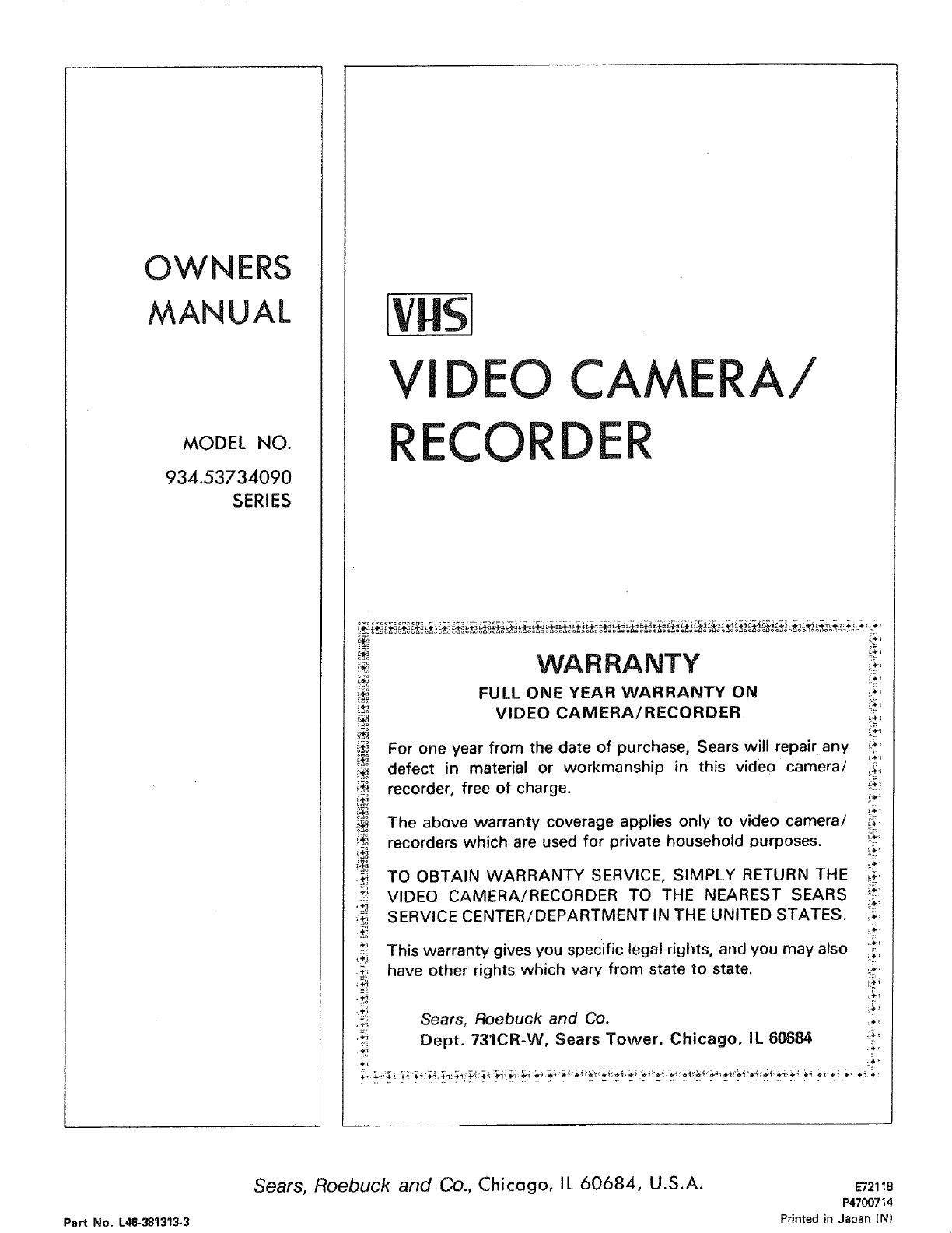
OWNERS
MANUAL
MODEL NO.
934.53734090
SERIES
[vHsj
VIDEO C
ECORDE
ERA/
WARRANTY
FULL ONE YEAR WARRANTY ON
VIDEO CAMERA/RECORDER
For one year from the date of purchase, Sears will repair any
defect in material or workmanship in this video camera/
recorder, free of charge.
The above warranty coverage applies only to video camera/
recorders which are used for private household purposes.
TO OBTAIN WARRANTY SERVICE, SIMPLY RETURN THE
VIDEO CAMERA/RECORDER TO THE NEAREST SEARS
SERVICE CENTER/DEPARTMENT IN THE UNITED STATES.
This warranty gives you specific legal rights, and you may also
have other rights which vary from state to state.
%-
Sears, Roebuck and Co ....
Dept. 731CR-W, Sears Tower, Chicago, IL 60684 ':*'
Part No. L46-381313-3
Sears, Roebuck and Co., Chicago, IL 60684, U.S.A. E72118
P4700714
Printed in Japan (N)
