La Crosse Technology 01PC WS2010 PC Interface User Manual users manual
La Crosse Technology Ltd. WS2010 PC Interface users manual
users manual

Page 1 of 4
Instruction Summary: WS2010PC Professional Wireless Weather Computer Center
Table of Contents
1.0 Set Up (Page 1)
1.1. Installing Batteries and Magnets
1.2. Test Mode
1.3. Calibration Setting
1.4. Return to Normal Operation
2.0 Mounting Instructions (Page 2)
2.1. Location of Sensors
2.2. Rain Gauge Mounting
2.3. Wind Sensor Mounting
2.4. Outdoor Temperature & Humidity
Sensor Mounting
2.5. Indoor Temperature, Humidity &
Pressure Sensor Mounting
2.6. Receiver Mounting
3.0 General Operation (Page 3)
3.1. Current Information
3.2. Indoor Temperature & Humidity
3.3. Outdoor Temperature & Humidity
3.4. Air Pressure
3.5. Rainfall
3.6. Wind Speed and Direction
3.7. Display Illustration
4.0 Minimum and Maximum (Page 4)
4.1. Viewing All Minimum & Maximums
4.2. Displayed Description
4.3. Outdoor Sensor Selection
4.4. Dewpoint and Windchill
4.5. Individual Minimum & Maximums
4.6. Resetting Minimum & Maximums
5.0 Alarm Function (Page 4)
5.1. Alarm Description
5.2. Programming Alarms
5.3. Alarm Occurrence
1.0 Set Up
1.1. Installing Batteries and Magnets:
1.1.1. IMPORTANT: Set up sensors first. Install batteries into receiver only when all sensors have been operating
for at least ten minutes. Failure to do this may result in poor reception. If this occurs, remove batteries and
magnets for at least one minute and follow set up instructions.
1.1.2. Plug the PC Interface into the computer
1.1.3. Install the program by inserting the CD and following instructions (if program does not automatically run,
double-click D:/Setup.exe)
1.2. Test Mode: After installing batteries and magnets in the sensors and receiver, they will go into test mode. During
this time, no buttons should be pressed.
1.2.1. The display on your computer will cycle through the indoor temperature, humidity and pressure, outdoor
temperature and humidity, rainfall amount, and wind speed/direction. At first, the cycle will last for only a few
seconds on each display. During this time, it is recommended that you place the sensors in desired locations
to assure reception.
1.2.2. After several successful cycles, the receiver will display each reading for one minute. Once all data has been
received, usually after ten minutes, you may end the test mode. It will automatically end after 30 minutes.
1.3. Calibration (To be done after the completion of the test mode—approximately 10 minutes.)
1.3.1. Select File Calibr. to enter the calibration mode. (“Calibration” is displayed)
1.3.2. “0000” is displayed under the air pressure display
1.3.2.1. Choose the unit of measurement; inHg or hPa (millibars)
1.3.2.2. Set the height (in meters) above sea level. The WS2010PC shows absolute pressure. To measure
relative pressure, the height above sea level needs to be set. Multiply feet by .305 to get meters.
1.3.3. “370” is displayed under the rainfall display
1.3.3.1. This is the “Rain-volume-measurement”. This normally doesn’t need to be adjusted. See instruction
manual (4.2) for directions.
1.3.3.2. Choose the unit of measurement--inches or mm.
1.3.4. Time & Date Setting:
1.3.4.1. Set the time and date
1.3.5. A “7” is displayed in the indoor temperature, wind speed and rainfall displays
1.3.5.1. These should always be set to “7” unless there happens to be two WS2010PC in operation near one
another (i.e. a neighbor has a WS2010PC). If this is the case, please call La Crosse Technology for
directions. If the number is not “7”, information from that sensor will not be displayed.
1.3.5.2. Select °F to °C.
1.4. Normal Operation: Press the Store key to return to normal operation. If no button is pressed for one minute, the
display will return to the normal operating mode. The Weather Station is now operational. If any problems
occur, see section 6 of the instruction manual.
Page 2 of 4
2.0 Mounting Instructions
Mounting hardware is included: (4) u-bolts; (8) 2¼” screws; (8) 1¼” screws; (2) 9/16” screws; (2) 5/16” machine screws; (2)
5/16” sheet metal screws; (8) washers; (8) wall spacers for 2¼” screws (beige); (8) wall spacers for 1¼” screws (green).
2.1. Location of Sensors
2.1.1. It is easiest to locate sensors while the receiver and sensors are in the test mode. Mount only after good
reception is achieved in desired location. Be sure the receiver can pick up the
signals from different locations if desired.
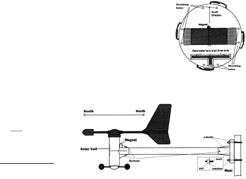
2.2. Rain Gauge Mounting
2.2.1. Locate away from anything that could interfere with the collection of rain. Keep
away from buildings, downspouts, trees, and sprinklers. The solar sensor
should receive as much light as possible.
2.2.2. It is important to mount the rain gauge level to achieve accuracy.
2.2.2.1. One method of leveling the sensor is as follows: Position sensor in
desired location. Take off cover. Fill the “T”-shaped depression in the
base with water. The rain gauge is level when all three water levels are
equal. Be sure to replace cover correctly with magnets facing each other.
2.2.3. The rain sensor can be permanently mounted to wood (i.e. a deck railing or piece of 2”x6” board) using screw
holes and included (8) 1¼” screws. If necessary, drill ¼” holes, tap in green spacers, and insert screws.
2.3. Wind Sensor Mounting
2.3.1. Ideally should be mounted on a 1¼” mast
on rooftop or mounted on a wall.
2.3.2. The solar sensor must face due south to
register the correct direction. Mount wind
sensor away from obstacles that will
block the wind. The 14” aluminum post
must also be completely horizontal.
2.3.3. Attach the included 14” aluminum post to
the wind sensor using included (2) 9/16”
screws. Attach mounting bracket to other end of post using the included (2) 5/16” sheet metal screws.
2.3.4. Attach assembly to mast using u-bolts or to wall using included 2¼” screws. If necessary, use beige spacers
for wall mounting with screws.
2.3.5. The solar cell must be facing dew south for proper reading of wind direction.
2.4. Outdoor Temperature & Humidity Sensor Mounting
2.4.1. Can be mounted on a mast or a wall. It should be out of direct sunlight; under a roof gable is ideal.
2.4.2. The mounting bracket is the same as the one for the wind sensor. Use (2) u-bolts for mounting on a mast or
(4) 2¼” screws (use beige spacers if necessary) for wall mounting.
2.4.3. Mount the bracket on vertical surface then attach sensor using (2) 5/16” machine screws. The rain cap must be
on the top of the sensor.
2.5. Indoor Temperature, Humidity & Pressure Sensor Mounting
2.5.1. Can be mounted on a wall or simply placed on a shelf.
2.5.2. This sensor transmits the temperature, humidity, and the pressure.
2.5.3. Do not place the sensor in direct sunlight or high humidity location (bathroom), or expose to water.
2.5.4. The indoor sensor can be hung by the mounting hole located on the back or placed on a stable surface.
2.5.5. Since this sensor’s data is continually displayed, it is ideal to locate it in the main living area.
2.6. Receiver Mounting
2.6.1. This can be placed anywhere reception is good. It is not necessary to keep the receiver plugged in to the
computer. The receiver will store data until it is loaded. It can remain attached to the computer.
Page 3 of 4
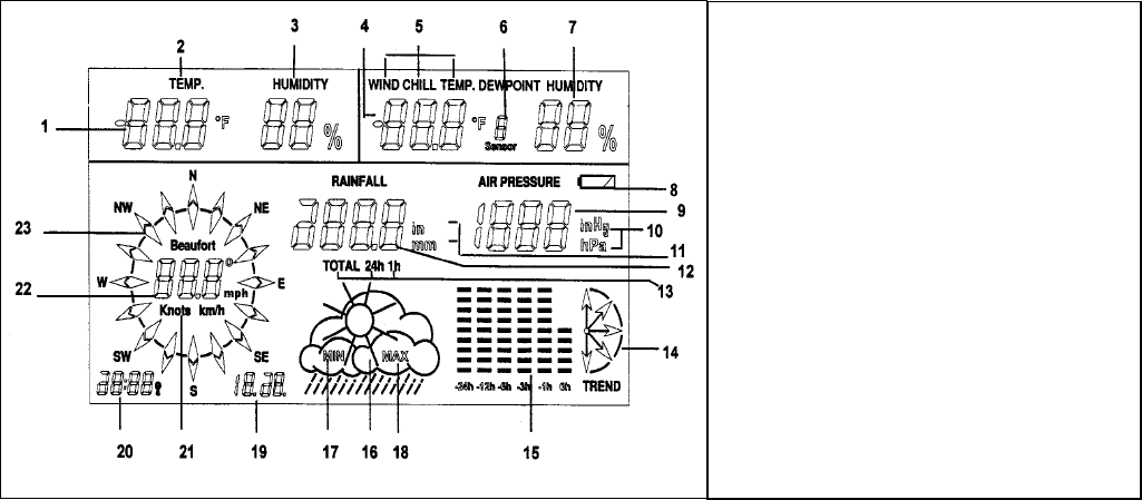
1. Indoor temperature
2. Temperature measurement
3. Indoor humidity
4. Selected temperature sensor
5. Temperature measurement
6. Indication of sensor number
7. Humidity of selected sensor
8. Low battery indication
9. Pressure indication
10. Pressure unit (inHg or hPa)
11. Rainfall unit (inches or mm)
12. Rainfall rate
13. Period of rainfall rate (1-hour, 24-hours, total)
14. Pressure trend indicator
15. Pressure history of past 24 hours
16. Weather forecast symbol
17. Indicates minimum readings displayed
18. Indicates maximum readings displayed
19. Date
20. Time
21. Wind speed units (mph, km/h, knots, or Beaufort)
22. Wind speed indicator or direction in °
23. Wind rose of direction in 5° increments
3.0 General Operation
3.1. Once the program is started, you can view all information by selecting View-Weather Display
3.2. Current information is displayed simultaneously in normal operation.
3.2.1. Indoor temperature, humidity, outdoor temperature, humidity, pressure, pressure trend, 24-hour pressure
history bar chart, rainfall rate, forecast icon, wind speed and direction, time and date.
3.3. Indoor temperature and humidity are displayed in the upper left.
3.4. Outdoor temperature and humidity are displayed n the upper right.
3.4.1. Press Outd. key once to view dewpoint, twice to view wind chill, three times to view normal temperature
3.4.2. If you have more than one outdoor sensor (note that additional sensors are available for indoor as well, but
will be displayed in the “outdoor” display), press the Sensor key to cycle through (up to eight).
3.5. Air pressure information is displayed on the right side
3.5.1. Current air pressure is displayed under the outdoor humidity
3.5.2. Pressure trend indicator is in lower left corner ( quickly rising, steadily rising, èsteady, steadily falling,
ê quickly falling)
3.5.3. The 24-hour history bar chart is to the left of the trend indicator. This indicates graphically the history of the
pressure for the past 24 hours. Current pressure (“0h”) is always shown with five bars. The other bars will be
more or less depending on the past pressure. Fewer bars indicates the pressure was lower, more bars
indicates the pressure was higher. Each bar represents a change of 2 millibars (hPa).
3.5.4. The weather forecast icon is to the left of the bar chart. It will indicate rainy, cloudy, partly cloudy or sunny.
This forecast is based on the pressure trend. Rising pressure generally indicates fair weather. Falling
pressure generally indicates cloudy or rainy weather. The amount of pressure change and the period it occurs
in determines the forecast. Actual weather is based on many other variables; thus, a forecast by pressure
trend is about 75% accurate.
3.6. Rainfall rate is displayed in the center of the LCD.
3.6.1. Pressing the Rain key cycles through the totals of rain for last hour, last 24 hours, or total since last reset.
3.6.2. To view the time and date of the last reset, press the Reset key briefly. The time and date will display in the
lower left corner. It will display for five seconds, then display the current time and date.
3.6.3. To reset the total accumulated rainfall, press and hold the Reset key for four seconds. There will be an
audible beep and the screen will blink once. The total rainfall amount is now “0.0”. The 24-hour and last hour
totals cannot be reset.
3.7. Wind speed and direction is on the left side of the LCD.
3.7.1. The average wind direction between transmissions is displayed as arrows on the wind rose.
3.7.2. In the middle of the wind rose is the wind speed or direction. Pressing the Wind key cycles through the
measurement options. MphèKnots èm/s èèkm/h BeaufortèDirection in 5° increments.
3.7 Display
Page 4 of 4
4.0 Minimum and maximum options.
4.1. Press the Min/Max key once to view all minimum values, and twice to view all the maximum values.
4.2. Minimum and maximum values are stored for indoor temperature, indoor humidity, outdoor temperature, outdoor humidity,
and pressure. Rainfall and wind speed maximums are also stored. If the wind or rain maximums do not display, press the
Rain or Wind key.
4.3. Press the Sensor key to scroll through all outdoor temperature/humidity sensors (if available).
4.4. Press the Outd. key to switch between outdoor temperature, dewpoint, and windchill.
4.5. Press the or key to scroll through each individual value and view the time and date of occurrence.
4.5.1. The order is as follows for pressing the key (the ç key reverses the order):
4.5.1.1. Indoor temperature
4.5.1.2. Indoor humidity
4.5.1.3. Outdoor temperature. Press the Sensor key to select another sensor, if available. Press the Outd. key to view
dewpoint and windchill.
4.5.1.4. Outdoor humidity
4.5.1.5. Wind speed (maximum only). Press the Wind key to change unit of measurement.
4.5.1.6. Rainfall amount (maximum only). Press the Rain key to switch to 1-hour or 24-hours.
4.5.1.7. Air pressure
4.5.1.8. All values.
4.5.2. Corresponding time and date are displayed for individual minimum values.
4.5.3. To switch between minimum and maximum values, press the Min/Max key at any time.
4.5.4. To exit, press the çor key until all values are displayed, then press the Min/Max key.
4.5.5. If no button is pressed for one minute, the display will return to the normal operating mode.
4.6. Minimum & Maximum Reset: To reset minimum and/or maximum values, press and hold the Reset key for three seconds.
A tone will beep and the display will show “- - -“. If this is done while viewing all minimum (or maximum) values, all minimum
(or maximum) values will be reset. If this is done while viewing an individual value, only that value will be reset.
5.0 Alarm Function
5.1. Alarm Description: The alarm function on the WS2010 enables the user to set up to 39 alarms (if the maximum of nine
temperature/humidity sensors are used) to sound when a chosen value rises above the set maximum or below the set
minimum. (For example, set the alarm to sound when the temperature falls below freezing.)
5.1.1. The alarm can be set for each temperature, humidity, pressure, and wind speed (maximum only) values.
5.2. Alarm Programming Mode: Press the and ç keys simultaneously to enter the alarm programming mode.
5.2.1. “Program Mode” will be displayed below the temperature display
5.2.2. The minimum alarm values are displayed. To view the maximum values, press the Min/Max key.
5.2.3. Press the ç or key to view each value. Use the – or + key to increase or decrease the set value. To advance more
rapidly, press the Fast key at the same time as the – or + key.
5.2.4. The following is the order by pressing the key (the ç key reverses the order):
5.2.4.1. Indoor temperature.
5.2.4.2. Indoor humidity.
5.2.4.3. Outdoor temperature. Press the Sensor key to select the desired sensor, if available.
5.2.4.4. Outdoor humidity. Press the Sensor key to select the desired sensor, if available.
5.2.4.5. Wind speed (maximum only). The measurement unit (mph, km/h, etc.) cannot be changed from the alarm
programming mode; it must be changed from the normal operating mode (see section 3.6.2).
5.2.4.6. Air pressure. The measurement unit can only be changed in the calibration mode (section 1.3.2.1).
5.2.4.7. All alarm values are displayed.
5.2.4.8. To store set alarm values, press the Store key or wait for one minute. The alarm is automatically active.
5.2.5. To reset press and hold the Reset key for three seconds. An audible tone will beep and the display will display “- - -“. If
this is done while viewing all minimum or maximum alarm values, all corresponding values will be reset. If this is done
while viewing an individual alarm value, only that value will be reset.
5.3. Alarm Occurrence: When a value rises above or falls lower than a set value, the receiver will beep five times twice.
5.3.1. The receiver will only display “AL” in the lower left corner and the value of the alarm (i.e. “32° F”)
5.3.2. To deactivate the alarm, press the Alarm key. The display returns to the normal operating mode.
5.3.2.1. The alarm will sound again if another value rises above or falls below the set alarm value.
5.3.2.2. To view which values are above or below the alarm values (if any), press the Alarm key. Press the Alarm key to
return to the normal operating mode.