La Crosse Technology M-02 TEMPERATURE TRANSMITTER User Manual TX61U IT e2
La Crosse Technology Ltd. TEMPERATURE TRANSMITTER TX61U IT e2
Users Manual
1
TX
TXTX
TX61
6161
61U
UU
U-
--
-IT
IT IT
IT
Wireless
Wireless Wireless
Wireless 915
915915
915 MHz
MHz MHz
MHz
Solar Temperature
Solar TemperatureSolar Temperature
Solar Temperature Transmitter
Transmitter Transmitter
Transmitter
The TX61U-IT Solar Temperature Transmitter measures the outdoor
temperature and transfers the data to the Temperature Station.
INVENTORY OF CONTENTS
INVENTORY OF CONTENTS INVENTORY OF CONTENTS
INVENTORY OF CONTENTS
1. One TX61U-IT Solar Temperature Transmitter.
2. Mounting hardware.
3. Instruction manual.
IMPORTANT NOTES ON SETUP AND OPERATION
• Important Notes on set-up and operation the Solar Temperature
Transmitter should be placed in a dry area.
• The Solar Temperature Transmitter consumes solar power and internal
rechargeable batteries.
• Fog and mist will not harm your but direct rain must be avoided.
• The Solar Temperature Transmitter has a range of 330 feet (100 m). Keep
in mind that the 330 feet is in open air with no obstructions and that radio
waves DO NOT curve around objects. Actual transmission range will vary
depending on what is in the path of the signal. Each obstruction (roof,
walls, floors, ceilings, thick trees, etc.) will effectively cut signal range in
half.
Example: A wireless Weather/ Temperature Station with a 330 feet (100
m) range is mounted on an interior wall, so that the signal has to pass
through one interior wall, one exterior wall, and across the 10 feet (3 m)
width of the room between the 2 walls. The first wall will reduce the range
to 165 feet (50 m), and the second wall will reduce the range to 87 feet
(26.5 m). Factoring in the 10 foot room, this leaves a maximum of 77 feet
(23.5 m) of remaining signal range.
This allowance is typically enough for a frame wall with non-metallic siding;
however certain materials can reduce range even further. Metal siding,
stucco, and some types of glass can reduce signal range by as much as ¾
or more, compared to the ½ reduction typical of most obstructions. It is
possible to receive a signal through these materials, however maximum
range will be much less due to their tendency to absorb or reflect a much
larger portion of the sensor’s signal.
• The Solar Temperature Transmitter measures and transmits signal about
every 8 seconds when its battery voltage is higher than 2.4V.
• After the batteries of Temperature Station have been installed, the
Temperature Station will search for the signal of Solar Temperature
Transmitter for duration of few minutes. If the connection process is failed,
user shall make sure the units are within range of each other, or restart the
transmitter starts up procedure again.
IDLE MODE
IDLE MODEIDLE MODE
IDLE MODE
This mode aims to reduce power consumption of the transmitter. Under this
mode, the transmitter turns off LCD, stops the transmission of signal, checks the
battery voltage and detects the solar cell condition. The IDLE mode happens:
• if the battery voltage is lower than 2.4V, “LO” will be displayed on the LCD
for a short while (around 2 seconds) before the transmitter enters into IDLE
mode.
Note: The transmitter will check and charge up the internal rechargeable battery
automatically, when it detects the battery voltage rises up to 2.5V, the
LCD turns on and the transmission of signal starts again.
STOP MODE
STOP MODE STOP MODE
STOP MODE
It is the most energy saving mode. Under this mode, the transmitter turns off
LCD, no transmission of signal and no checking battery voltage. The transmitter
shows “StP” on the LCD for a short while (around 2 seconds) before it enters this
mode. The STOP mode happens:
• if the user covers the solar cell for 10 seconds and presses the reset
button.
• if the transmitter is placed in the dark environment for 24 hours.
Note: To wake up the Solar Temperature Transmitter, user has to press the
reset button on the transmitter to wake it up again. If the battery voltage is
higher than 2.4V, the LCD turns on and the transmission of signal starts
again. However, if the battery voltage is lower than 2.4V, “LO” will be
displayed and the transmitter enters into IDLE mode. User should place
the transmitter under a bright environment in order to charge up the
rechargeable batteries inside the transmitter.
SETTING UP
SETTING UPSETTING UP
SETTING UP
1. To start the operation, first, press the reset button on the Solar
Temperature Transmitter. Normally, all segments of the LCD will light up
briefly. The code number and the security code (for example, “20”) will be
displayed sequentially. Next, the battery voltage will be shown on the
LCD, it should be higher than 2.4V in order to maintain the normal
operation. The instant temperature can be read on the transmitter, and
the transmitter starts the transmission of signal.
2. Within 2 minutes of the start up of transmitter, insert the batteries to the
Temperature Station. Once the batteries of the Temperature Station are
in place, all segments of the Temperature Station’s LCD will light up
briefly. The indoor data will be first displayed on the Temperature Station,
and then the outdoor data. Following the indoor temperature and the time
as 12:00 will be displayed on the Temperature Station. If they are not
shown in the LCD of Temperature Station after 30 seconds, user should
reinstall the batteries of the Temperature Station again. Once the indoor
data is displayed user may proceed to the next step for receiving outdoor
data.
3. After the Temperature station is powered up, it will start receiving outdoor
data signal from the Solar Temperature Transmitter. During the process,
the signal reception and re-synchronization process will try the following
frequencies: 903MHz, 915MHz and 927MHz. If this does not happen after
5 minutes, the batteries of the Temperature Station should be removed
and reset the Solar Temperature Transmitter from step 1.
4. In order to ensure better reception and transmission, this should under
good conditions be a distance no more than 330 feet (100 meters)
between the final position of the Temperature Station and the Solar
Temperature Transmitter.
MOUNTING
MOUNTINGMOUNTING
MOUNTING
THE TEMPERATURE TRANSMITTER
The Solar Temperature Transmitter can be mounted onto a wall with the use of
screws
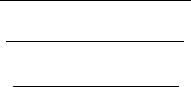
MOUNTING WITH SCREWS
1. Remove the mounting bracket from the Solar
Temperature Transmitter.
2. Place the mounting bracket over the desired location.
3. Through the two screw holes of the bracket, mark the
mounting surface with a pencil.
4. Screw mounting bracket onto the mounting surface.
Ensure that the screws are tight against the bracket.
5. Insert the Solar Temperature Transmitter into the
bracket.
Table standing or others
With the mounting bracket installed at the bottom or the top of
the transmitter, user can place it on any flat surface.
Note: Before permanently fixing the remote temperature sensor
wall base, place all units in the desired locations to check
that the outdoor temperature readings are receivable. In
event that the signal is not received, relocate the remote
temperature sensor or move them slightly as this may
help the signal reception.
MAINTENANCE AND CARE
MAINTENANCE AND CAREMAINTENANCE AND CARE
MAINTENANCE AND CARE
• Extreme temperatures, vibration, and shock should be avoided to prevent
damage to the units.
• Clean displays and units with a soft, damp cloth. Do not use solvents or
scouring agents; they may mark the displays and casings.
• Do not submerge in water.
• Immediately remove all low powered batteries to avoid leakage and damage.
• Opening the casings invalidates the warranty. Do not try to repair the unit.
Contact La Crosse Technology for repairs.
SPECIFICATIONS
SPECIFICATIONSSPECIFICATIONS
SPECIFICATIONS
Note: Detailed set-up procedures of the Temperature Station and the Solar
Temperature Transmitter refer to the main operation manual of
Temperature Station.
Data measuring range:
Outdoor temperature: -39.8 °F to 139.8°F with 0.2°F resolution
“OFL” displayed if outside this range
Transmission range: 330 feet (100 m) in open space
Operating voltage: 2.4V or higher than 2.4V
Dimensions (H x W x D): 100 x 25.3 x 43 mm
WARRANTY INFORMA
WARRANTY INFORMAWARRANTY INFORMA
WARRANTY INFORMATION
TIONTION
TION
La Crosse Technology, Ltd provides a 1-year limited warranty on this product
against manufacturing defects in materials and workmanship.
This limited warranty begins on the original date of purchase, is valid only on
products purchased and used in North America and only to the original purchaser
of this product. To receive warranty service, the purchaser must contact La
Crosse Technology, Ltd for problem determination and service procedures.
Warranty service can only be performed by a La Crosse Technology, Ltd
authorized service center. The original dated bill of sale must be presented upon
request as proof of purchase to La Crosse Technology, Ltd or La Crosse
Technology, Ltd’s authorized service center.
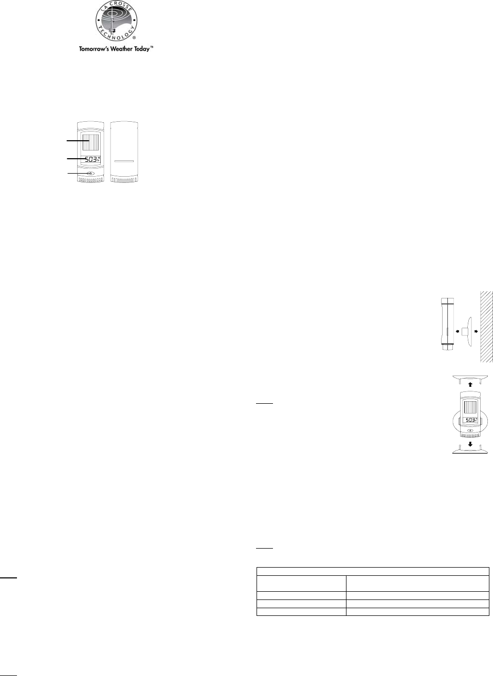
Solar cell
LCD
Reset button
2
La Crosse Technology, Ltd will repair or replace this product, at our option and at
no charge as stipulated herein, with new or reconditioned parts or products if
found to be defective during the limited warranty period specified above. All
replaced parts and products become the property of La Crosse Technology, Ltd
and must be returned to La Crosse Technology, Ltd. Replacement parts and
products assume the remaining original warranty, or ninety (90) days, whichever
is longer. La Crosse Technology, Ltd will pay all expenses for labor and
materials for all repairs covered by this warranty. If necessary repairs are not
covered by this warranty, or if a product is examined which is not in need or
repair, you will be charged for the repairs or examination. The owner must pay
any shipping charges incurred in getting your La Crosse Technology, Ltd product
to a La Crosse Technology, Ltd authorized service center. La Crosse
Technology, Ltd will pay ground return shipping charges to the owner of the
product to a USA address only.
Your La Crosse Technology, Ltd warranty covers all defects in material and
workmanship with the following specified exceptions: (1) damage caused by
accident, unreasonable use or neglect (including the lack of reasonable and
necessary maintenance); (2) damage occurring during shipment (claims must be
presented to the carrier); (3) damage to, or deterioration of, any accessory or
decorative surface; (4) damage resulting from failure to follow instructions
contained in your owner’s manual; (5) damage resulting from the performance of
repairs or alterations by someone other than an authorized La Crosse
Technology, Ltd authorized service center; (6) units used for other than home
use (7) applications and uses that this product was not intended or (8) the
products inability to receive a signal due to any source of interference.. This
warranty covers only actual defects within the product itself, and does not cover
the cost of installation or removal from a fixed installation, normal set-up or
adjustments, claims based on misrepresentation by the seller or performance
variations resulting from installation-related circumstances.
LA CROSSE TECHNOLOGY, LTD WILL NOT ASSUME LIABILITY FOR
INCIDENTAL, CONSEQUENTIAL, PUNITIVE, OR OTHER SIMILAR DAMAGES
ASSOCIATED WITH THE OPERATION OR MALFUNCTION OF THIS
PRODUCT. THIS PRODUCT IS NOT TO BE USED FOR MEDICAL
PURPOSES OR FOR PUBLIC INFORMATION. THIS PRODUCT IS NOT A
TOY. KEEP OUT OF CHILDREN’S REACH.
This warranty gives you specific legal rights. You may also have other rights
specific to your State. Some States do no allow the exclusion of consequential
or incidental damages therefore the above exclusion of limitation may not apply
to you.
For warranty work, technical support, or information contact:
La Crosse Technology, Ltd
190 Main Street
La Crescent, MN 55947
Phone: 507.895.7095
Fax: 507.895.2820
e-mail:
support@lacrossetechnology.com
(warranty work)
sales@lacrossetechnology.com
(information on other products)
web:
www.lacrossetechnology.com
FCC DISCLAIMER
FCC DISCLAIMERFCC DISCLAIMER
FCC DISCLAIMER
This device complies with part 15 of the FCC rules. Operation is subject to the
following two conditions:
(1) This device may not cause harmful interference.
(2) This device must accept any interference received, including
interference that may cause undesired operation.
Changes or modifications not expressly approved by the party responsible for compliance
could void the user's authority to operate the equipment.
NOTE: This equipment has been tested and found to comply with the limits for a
Class B digital device, pursuant to Part 15 of the FCC Rules. These limits are
designed to provide reasonable protection against harmful interference in a
residential installation. This equipment generates, uses and can radiate radio
frequency energy and, if not installed and used in accordance with the
instructions, may cause harmful interference to radio communications. However,
there is no guarantee that interference will not occur in a particular installation.
If this equipment does cause harmful interference to radio or television reception,
which can be determined by turning the equipment off and on, the user is
encouraged to try to correct the interference by one or more of the following
measures:
-- Reorient or relocate the receiving antenna.
-- Increase the separation between the equipment and receiver.
-- Connect the equipment into an outlet on a circuit different
from that to which the receiver is connected.
-- Consult the dealer or an experienced radio/TV technician for help.
All rights reserved. This handbook must not be reproduced in any form, even in
excerpts, or duplicated or processed using electronic, mechanical or chemical
procedures without written permission of the publisher.
This handbook may contain mistakes and printing errors. The information in this
handbook is regularly checked and corrections made in the next issue. We
accept no liability for technical mistakes or printing errors, or their consequences.
All trademarks and patents are acknowledged.