La Crosse Technology M-16 WEATHER STATION User Manual
La Crosse Technology Ltd. WEATHER STATION
User Manual
1
Quick Setup Guide – C86234 Professional Weather Station
The complete owner’s manual and downloadable software required for remote monitoring and alert features are available at:
www.lacrossetechnology.com/c86234
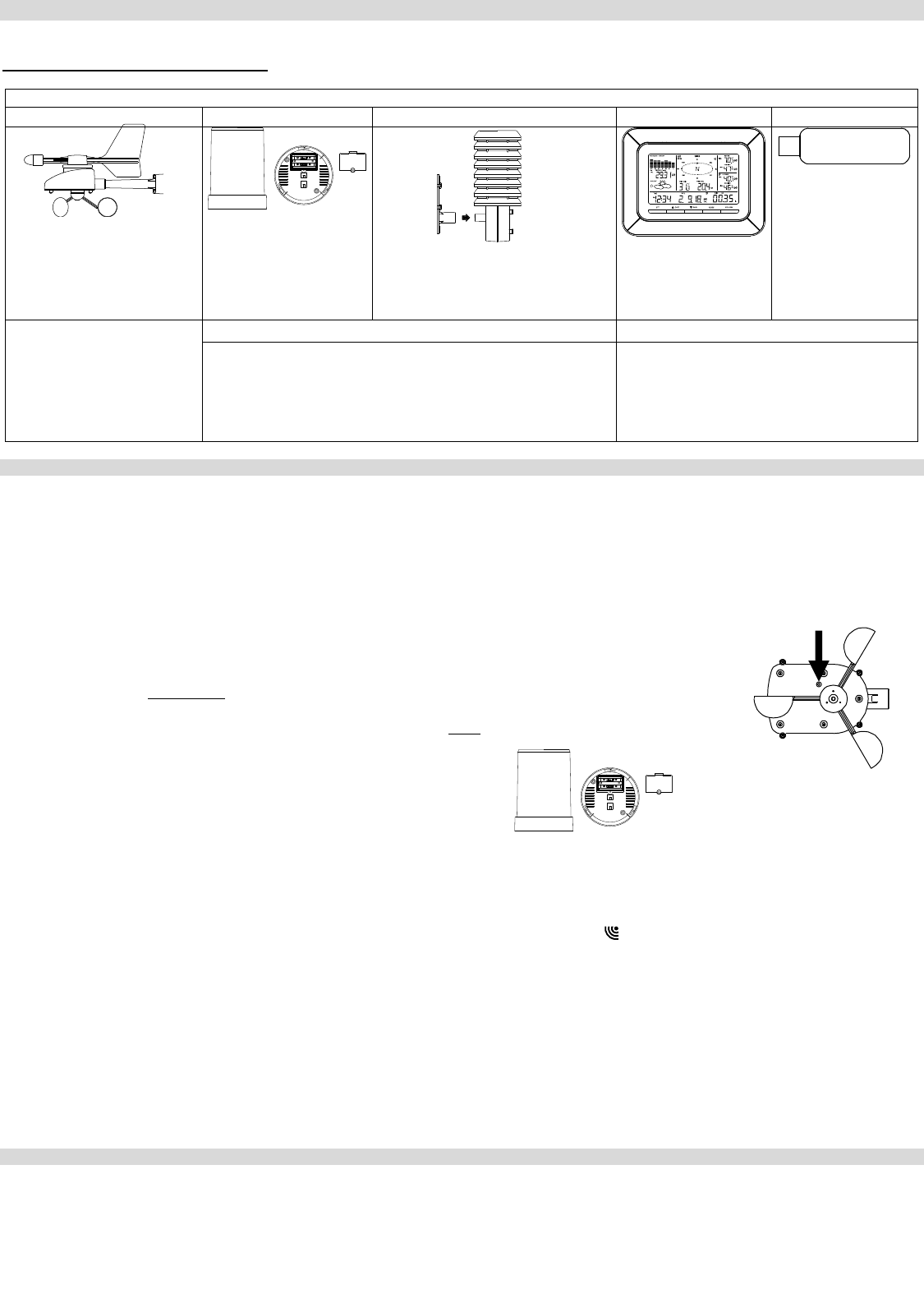
Carefully open the package and check that the following contents are complete:
Wind Sensor
Rain Sensor
Thermo-Hygro Sensor
Wireless Display
USB Transceiver
Mast holder
Right angle adaptor
1 x U-bolts
2 Washers + 2 Nuts
Plastic Reset Rod
Base sensor,
funnel top cover
and battery cover
(pre-assembled)
Airflow cover
Wall mount adapter
Mounting screws
Plastic anchors for screws
Foldout stand
USB wireless
interface for PC
All items, including Wind
Sensor, are Protected under
U.S. Patents: 5,978,738;
6,076,044; & 6,597,990
Wind Sensor also Protected
under U.S. Patent: 6,761,065;
RE42,057
Remote Monitoring & Alerts Activation Card
Heavy Weather PC Software
IMPORTANT!! Do Not Discard
Contains the Activation Key to enable
remote monitoring and alerts
Enables wireless computer connection
using the USB transceiver
SETUP INSTRUCTIONS STEP BY STEP:
IMPORTANT: Make sure to observe the correct polarity when inserting batteries. The "+" markings on the batteries must line up with the
diagrams inside the battery compartments. Inserting the batteries incorrectly may result in permanent damage to the units. During the
setup process, place the wireless display and the outdoor sensors on a surface with 5-10 feet between each sensor and the display. Only
use Alkaline Batteries, rechargeable batteries may not work:
STEP 1:
Complete initial setup on a table with all components within 10 feet of each other.
STEP 2:
It is important to allow sufficient light to reach the solar panel while activating the wind sensor. Make sure
the lights are on in the setup room and the solar panel is facing a 60W light bulb or brighter.
Ensure the panel is not covered, and then remove the black protective foil on the solar panel. Remove the
tape covering the reset hole.
Use the provided plastic reset rod to gently press the reset button once in the hole on the bottom of the
sensor.
STEP 3:
Insert two "AA" size batteries into the rain sensor with the correct polarity.
STEP 4:
Insert two "C" size batteries into the thermo-hygro sensor with the correct polarity. Allow all sensors to run for two minutes before inserting
batteries in the weather station.
STEP 5:
Insert three "C" size batteries into the wireless display with the correct polarity.
NOTE: Every time the wireless display receives data from the sensors, the wireless icons will blink once and then return to solid if the
last transmission was successful. A wind speed or rainfall amount that reads "0" does not mean reception failure. It means that there was
no wind or rain at the time of the last measurement. The thermo-hygro sensor syncs with the wind and rain sensors and sends all outdoor
sensor data to the display. The thermo-hygro sensor tries for 4 minutes to sync to the wind sensor and then 4 minutes for the rain sensor.
If not successful within 4 minutes, the thermo-hygro sensor will stop looking for the other sensors.
Wait 10 minutes for reception from all sensors before setting time and date or mounting sensors outside.
STEP 6:
Set Time and Date. See “Program Menu” below.
SETUP TROUBLESHOOTING: If the sensor data fails to display for any of the outdoor sensors within 10 minutes, (“- - -“are displayed),
remove the batteries from all units for 1 minute and start the Setup procedure again at Step 1.
Program Menu:
There are 5 function keys located on the unit: SET, UP ARROW, DOWN ARROW, ALARM, and MIN/MAX. Begin by holding the SET button
until the display flashes. When you press and release the SET button after each step, you will be moved to the next step. Save changes
and exit the program menu at any point by pressing the MIN/MAX button.
CONTRAST: Press and hold the SET button. LCD and a number from 1-8 will flash. Press and release the UP ARROW or DOWN
ARROW button to adjust the Contrast of the LCD. Press and release the SET button to confirm and continue.
HOUR: The Hour will flash. Press and release the UP ARROW or DOWN ARROW button until the correct Hour is shown. Press and
release the SET button to confirm and continue.
Press Reset Button on
Bottom of Wind Sensor
(Solar Panel Must Face
Light)
2
NOTE: When in 12h mode, there is only a 'PM' display, which appears under the word TIME. During the 'AM' hours this area will be blank.
MINUTES: The Minutes will flash. Press and release the UP ARROW or DOWN ARROW button until the correct Minutes are displayed.
Press and release the SET button to confirm and continue.
12/24-HOUR TIME: A 12h or 24h will flash. To change between 12h and 24h, press and release the UP ARROW or DOWN ARROW
button. Press and release the SET button to confirm and continue.
NOTE: When in 24-hour time the date will display Day first, then Month.
YEAR: The Year will flash. Press and release the UP ARROW or DOWN ARROW button to set the correct Year. Press and release the
SET button to confirm and continue.
MONTH: The Month will flash. Press and release the UP ARROW or DOWN ARROW button to set correct Month. Press and release the
SET button to confirm and continue.
DATE: The Date will flash. Press and release the UP ARROW or DOWN ARROW button to set the correct Date. Press and release the
SET button to confirm and continue.
FAHRENHEIT/CELSIUS: Degrees Fahrenheit or Celsius will flash in the Wind chill, Indoor and Outdoor temperature areas. Press and
release the UP ARROW or DOWN ARROW button to select between Fahrenheit and Celsius. Press and release the SET button to
confirm and continue.
WIND SPEED UNIT: Wind Speed units will flash. Press and release the UP ARROW or DOWN ARROW button to select from mph, m/s,
knots, Beaufort, or km/h. Press and release the SET button to confirm and continue.
RAIN UNIT: Rainfall Inches or Millimeters will flash. Press and release the UP ARROW or DOWN ARROW button to select in or mm.
Press and release the SET button to confirm and continue.
PRESSURE UNIT: The Air Pressure units (inHg or hPa) will flash. Press the UP ARROW or DOWN ARROW button to select inHg or hPa.
The Default setting is inHg. Press and release the SET button to confirm and continue.
RELATIVE PRESSURE SETTING: The Relative Air Pressure will flash. Press the UP ARROW or DOWN ARROW button to adjust the
Relative Air Pressure. Press and release the SET button to confirm and continue.
NOTE: Refer to your local weather station for an appropriate setting. It is important that this setting be adjusted for local conditions to
ensure forecast accuracy.
FORECAST SENSITIVITY: The Forecast Sensitivity will flash. The default setting of .09 works well in most areas of the country, however
in areas with relatively constant pressure this should be set to .06, (within 30 miles of the coast) and in areas with significant pressure
changes this should be set to 0.12 (within 30 miles of the desert). Press the UP ARROW or DOWN ARROW key to adjust. Press and
release the SET button to confirm and continue.
STORM ALARM SENSITIVITY: The Storm Alarm Sensitivity will flash. The default setting of .15 works well in most areas, however you
may need to adjust this level up or down depending on your local conditions. Use the UP ARROW or DOWN ARROW button to adjust.
Press and release the SET button to confirm and continue.
STORM ALARM: AON or AOFF will flash. This will turn the Storm Alarm ON or OFF. Use the UP ARROW or DOWN ARROW button to
toggle the Storm Alarm ON (AON) and OFF (AOFF). Press and release the SET button to confirm and continue.
WIND DIRECTION DISPLAY: The Dash in the Wind Compass will flash. Use the UP ARROW or DOWN ARROW button to select the
Wind Direction to be shown in degrees (dash) or letters NNW. Press and release the SET button to confirm and continue.
FACTORY RESET: Res off will be displayed. Use the UP ARROW or DOWN ARROW button to select on only if you wish to Factory
Reset the Weather Center. If you do not wish to restart the weather center, be sure the Res off is showing and press and release the SET
button to complete the program menu.
NOTE: To Factory Reset the weather center, select Res on and press the SET button to confirm. The station will begin to count down
numbers in the date area. When it is complete it will say Done. Then remove the batteries and follow the Restart up procedure.
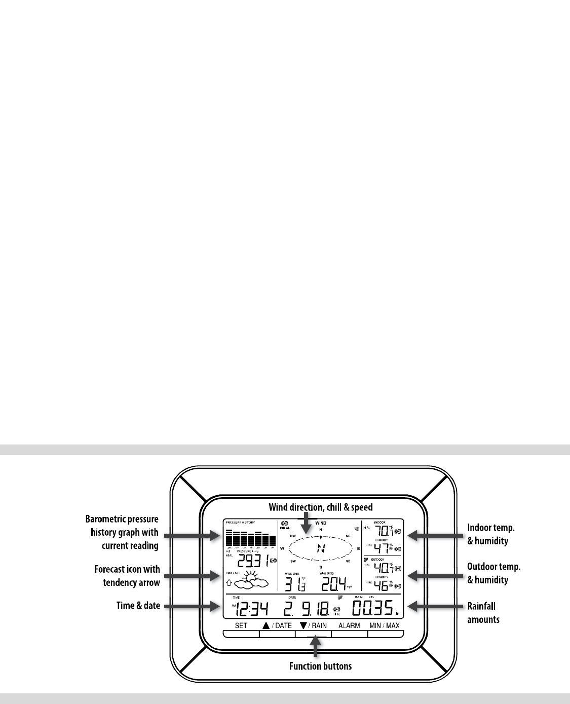
LCD Display:
Display Modes:
Press and release SET button to toggle between the display of Mode 1 or Mode 2:
MODE 1: MODE 2:
Wind Speed Wind Gust
Outdoor Temperature Dew Point Temperature
24 hr. Pressure History Graph 72 hr. Pressure History Graph
Other buttons provide multiple functions:
UP ARROW:
3
Press and release to switch between Date and Seconds displayed.
Press and hold until the station beeps to resync with sensors.
DOWN ARROW:
Press and release to view 1-hour, 24-hour, 1-week, 1-month or Total Rainfall.
Press and hold to resync the display with the software (must use usb stick).
Rain Display:
For all measurements, it is important time and date are set correctly on your display.
1-HOUR RAIN: The 1-hour rain reflects rain that has fallen from current time and back 1-hour. It updates every four minutes (15
measurements). The hour is not a fixed clock time measurement. It is literally an ongoing “last 60 minutes” timer.
24-HOUR RAIN: The 24-hour rain reflects the rain that has fallen from current time and back 24-hours. This is not a midnight to midnight
measurement. The day is not a fixed clock time measurement. It is literally an ongoing “last 24 hours” timer.
WEEKLY RAIN: The amount of rainfall of the previous week. The rainfall measurement starts counting on the second day after power up.
(Eg: if the unit is powered up on Monday day time, then the weekly rainfall is updated every Tuesday after 11:59 pm (23:59))
MONTHLY RAIN: Monthly rain reflects the previous month’s rain and will update 12AM the first day of the month.
TOTAL RAIN: Total rain will remain until you manually reset this value. Total rain reflects the rain from time of display set-up until you
manually reset the total rain.
Note: You must start a new history file on the PC if you reset the Total Rainfall on the weather station to avoid inaccuracies.
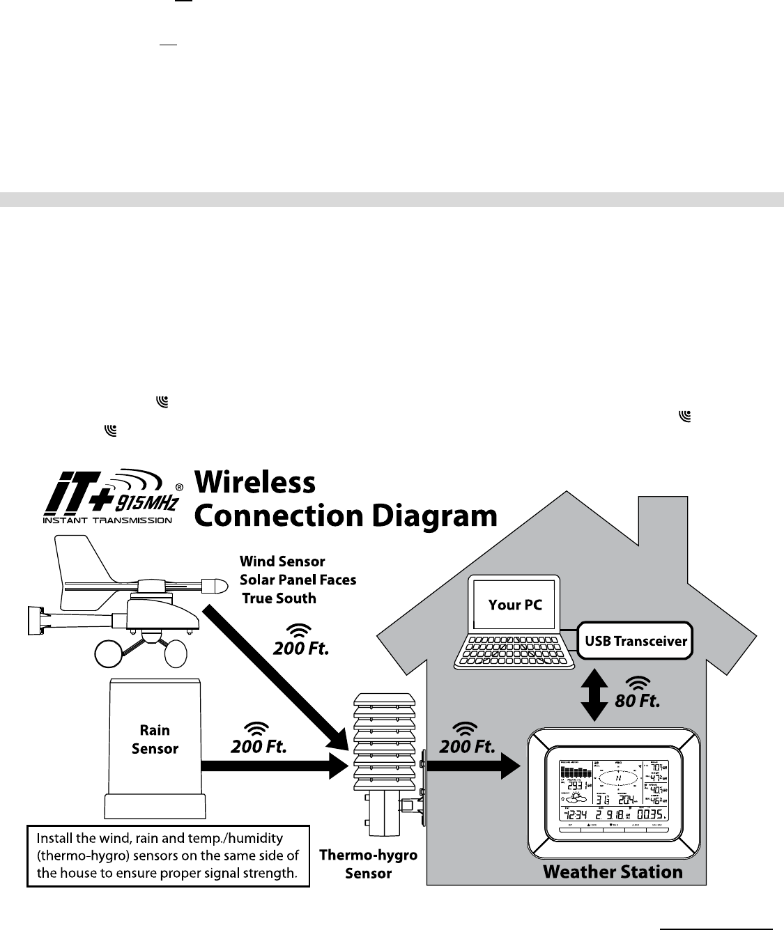
Mounting the sensors and placement of the wireless display:
IMPORTANT: Ensure that all of the sensor data can be received at the intended mounting locations before you drill mounting holes. The
outdoor sensors have a wireless range of 200-feet. Keep in mind that the 200-foot range equates to an open-air scenario with no
obstructions. Each obstruction (roof, walls, floors, ceilings, etc.) will reduce the range.
The thermo-hygro sensor measures outdoor temperature & humidity and collects the data from the wind and the rain sensors and sends all
outdoor weather data to the wireless display, so the thermo-hygro sensor must be within the 200-foot wireless range of the wireless display.
This allows the wind and rain sensors to be placed relative to the thermo-hygro sensor rather than the wireless display. See the Wireless
Connection Diagram below.
The wind and rain sensors must be mounted within the 200-foot wireless range of the thermo-hygro sensor and on the same side of the
house. In addition, 915 MHz sensors transmit better at a minimum mount height of 6 feet.
The wireless display must be within the 80-foot wireless range of the USB transceiver to send weather data to the PC.
If the sensor wireless icons drop from the display as you move them into their intended locations, the sensors may be too far from the
wireless display. Try moving the wireless display or the sensors closer and wait a few minutes to see if the wireless icons display again. If
the wireless icons are still not displayed after re-positioning the sensors or the wireless display, press and hold the UP ARROW (▲) key
for 2 seconds to re-synchronize the wireless display with the sensors.
Wind sensor
The wind sensor must be installed with the front of the sensor (the solar panel) facing true South, or the reported wind direction will not
be accurate. Mount within the 200-foot wireless range of the thermo-hygro sensor and on the same side of the house at a minimum height
4
of 6 feet. The roof may or may not be an ideal mounting location. Secure the main unit to the shaft of the mast holder. Use the right-angle
adaptor if the wind sensor will be mounted on a horizontal mast or surface.
Fasten the wind sensor to a suitable mast using the two U-bolts, washers and nuts included. Note: Mount the wind sensor onto a mast so
the wind can reach the sensor unobstructed from all directions for an accurate reading. The ideal mast is between 0.62" and 1.3” in diameter.
The wind sensor DOES NOT have replaceable batteries - it consumes solar power and charges the internal battery pack automatically.
Rain sensor
The rain sensor should be mounted on a level surface in an open area within the 200-foot wireless range of the thermo-hygro sensor and on
the same side of the house. Mount the rain sensor at least 6 feet off the ground level for optimum wireless transmission. The rain sensor
should be accessible to allow for periodic cleaning of debris or insects.
Thermo-Hygro Sensor
The thermo-hygro sensor is "weather resistant", but not "water proof". To ensure an extended life of your sensor, mount it in a semi-covered
place out of the elements. Minimum height is 6 feet; under the eaves on the North side of the house can be ideal to avoid the effects of
sunlight. Mount the sensor 18" down from the eaves to ensure optimum performance. This will assure the temperature of the air coming out
of the attic will not affect data collected by the sensor.
To wall mount the thermo-hygro sensor, fix the wall holder onto the desired wall using the included screws, plug the sensor firmly into the
wall holder and replace the rain cover if it is not already in place. Note: After mounting the units, if the weather data is not received, press
and hold the UP ARROW (▲) key for 2 seconds to synchronize the wireless display to the sensors.
Computer Connection and Remote Monitoring / Alerts
You have the option of using your weather station as a:
1. Standalone weather station – no computer or USB transceiver required.
2. Computer-connected weather station - Connect the USB transceiver to your computer for use with Heavy Weather Pro PC
software (included in the package on CD-ROM). You can also download the latest version of the Heavy Weather Pro PC software
at www.lacrossetechnology.com/c86234
3. Computer-connected weather station with remote monitoring and alerts – Connect the USB transceiver to your computer for
use with Heavy Weather Pro PC software (included in the package on CD-ROM). You can also download the latest version of the
Heavy Weather Pro PC software at www.lacrossetechnology.com/c86234. The included Remote Monitoring and Alerts Activation
Card has instructions for downloading the La Crosse Alerts software and the needed activation key to enable this feature.
Specifications
C86324 Display: 10.46” L x 1.35” W x 7.9” H TX63U-IT Solar Powered Wind:
(265.8 L x 34.4 W x 201.3 H mm) 9.84” L x 5.74” W x 7.57” H
2 “C” batteries (included) (250 L x 145.9 W x 192.3 H mm)
Integrated power-cell included
TX59UN-1-IT: 3.13” L x 3.54” W x 7.45” H
Thermo Hygro (79.4 L x 89.8 W x 189.3 H mm) USBTRX10: 3.2” L x .89” W x .35” H
2 “C” batteries (included) (81.8 L x 22.7 W x 9 H mm)
Powered by PC
TX58UN-IT Rain: 5.2” Dia. x 7.2” H
(131.6 Dia. x 182.7 H mm)
2 “AA” batteries (included)
Miscellaneous
EJMA2814L210
The complete instruction manual is available at:
www.lacrossetechnology.com/c86234
Le manuel d'instruction complet est disponible sur:
www.lacrossetechnology.com/c86234
El manual de instrucciones completo está disponible en:
www.lacrossetechnology.com/c86234
Limited 1-year Warranty
Contact Support: 1-608-782-1610
Product Registration: www.lacrossetechnology.com/support/register
For warranty work, technical support, or information contact:
La Crosse Technology, Ltd
2817 Losey Blvd. S.
La Crosse, WI 54601
Printed in China
FCC DISCLAIMER
This device complies with part 15 of the FCC rules. Operation is subject to the
following two conditions:
(1) This device may not cause harmful interference.
(2) This device must accept any interference received, including interference that
may cause undesired operation.
NOTE: THE MANUFACTURER IS NOT RESPONSIBLE FOR ANY RADIO OR
TV INTERFERENCE CAUSED BY UNAUTHORIZED MODIFICATIONS TO THIS
EQUIPMENT. SUCH MODIFICATIONS COULD VOID THE USER’S
AUTHORITY TO OPERATE THE EQUIPMENT.