La Crosse Technology TX24U Rain Transmitter User Manual WS 9004U LCU 2 eng
La Crosse Technology Ltd. Rain Transmitter WS 9004U LCU 2 eng
user manual
WS-9004U
915MHz
WIRELESS RAIN GAUGE
INSTRUCTION MANUAL

2
CONTENTS
03 introduction
03 features
04 setting up
06 function keys
07 operations
08 maintenance
09 specifications
09 liability disclaimer
10 warranty information
3
INTRODUCTION
Thank You and Congratulations on your purchase of this innovative Wireless
Rain Gauge for display of rainfall data through a wireless rainfall sensor. With
2 easy to use function keys, this unique product is perfect for gardeners and
weather buffs alike.
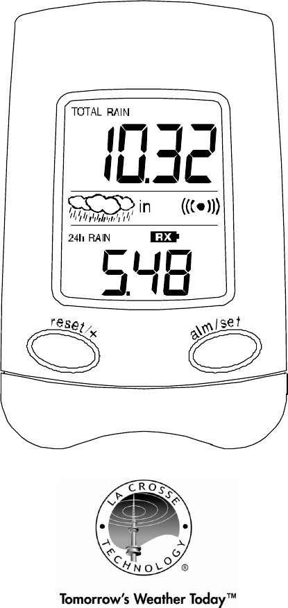
Wireless Rain Gauge (Receiver)
FEATURES
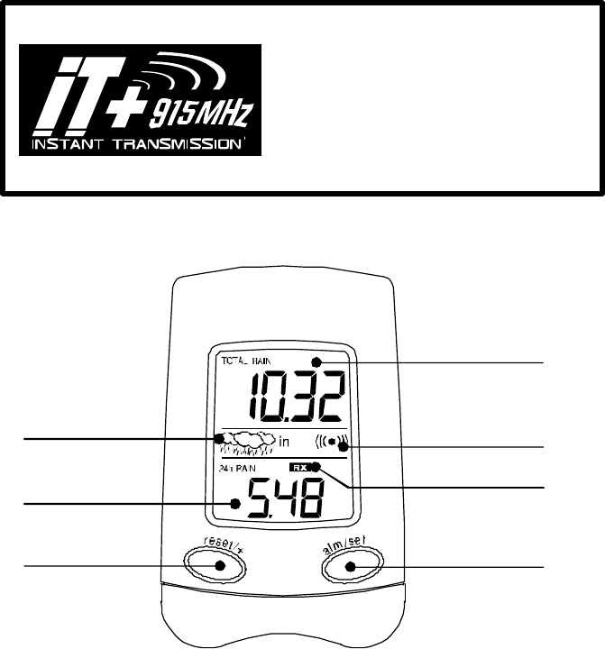
• 915 MHz Instant Data Transfer: Updates every 6 seconds
• Rainfall for Last 24 Hours
• User Defined Alarm for the past 24H Rainfall
• Current Rainfall Indicator, Light Rain & Heavy Rain Indicators
• Low Battery Indicator for Both Receiver & Rain Sensor
• Wall Hanging or Free Standing
Low Battery Indicator
Rainfall for
Past 24 Hours
User Defined
Rainfall Alarm
Light Rain &
Heavy Rain (shown)
Indicators
Total
Rainfall
Reset Total
Rainfall, Set Alarm
Vi
ew Alarm,
Enter Alarm
Setting
INSTANT TRANSMISSION is the state-of-the-
art new wireless transmission technology,
exclusively designed and developed by
LA CROSSE TECHNOLOGY. INSTANT
TRANSMISSION offers you an immediate
update (every 6 seconds!) of all your
outdoor data measured from the
transmitters: follow your climatic variations
in real
-
time!
This product offers:
4
SETTING UP
Hint: Use good quality Alkaline Batteries; avoid rechargeable
batteries.
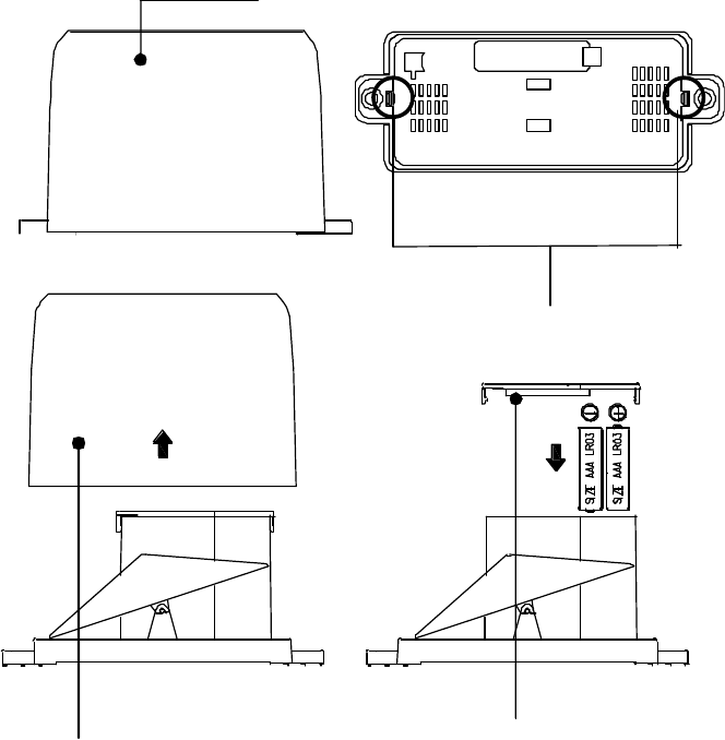
1. Have the receiver and the rain gauge 3 to 5 feet apart.
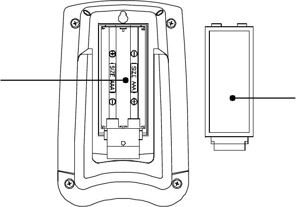
2. Place the batteries into the rain gauge FIRST and next into
the receiver. Observing the correct polarization, insert 2 “AAA”
Alkaline Batteries into the compartment at the back of the rain
gauge and replace the cover. Follow the same guidelines for
the receiver.
Rain Gauge
Rain Gauge
Cover
Press tabs back to
unlock Rain Gauge cover
Lift Rain Gauge cover to
access battery compartment
Remove battery cover
and insert batteries
5
3. DO NOT PRESS ANY BUTTONS FOR 15 MINUTES.
4. All segments of the LCD will light up briefly. Then 0.00 inch will
be displayed in both sections of the LCD. If the “0.00” is not
displayed after a few seconds, remove the batteries and wait
for at least 10 seconds before reinserting them.
5. Place the rain gauge in an appropriate location. The rain
gauge should be placed in a secure and flat location where it
can properly collect properly rain quantity without obstruction.
The rain gauge has a range of 330 feet. Keep in mind that the
330 feet is in open air with no obstructions and that radio
waves DO NOT curve to go around objects. Real-world
transmission range will vary depending on what is in the path
of the signal. Each obstruction (roof, walls, floors, ceilings,
thick trees, etc.) will effectively cut signal range in half.
Example: A wireless rain gauge receiver with a 330 feet
range is mounted on an interior wall, so that the signal has to
pass through one interior wall, one exterior wall, and across
the 10 feet width of the room between the 2 walls. The first
wall will reduce the range to 165 feet, and the second wall will
reduce the range to 87 feet. Factoring in the 10 foot room, this
leaves a maximum of 77 feet of remaining signal range.
Battery
Cover
Battery
Compartment
Receiver
6
This allowance is typically enough for a frame wall with non-
metallic siding; however certain materials can reduce range
even further. Metal siding, stucco, and some types of glass
can reduce signal range by as much as ¾ or more, compared
to the ½ reduction typical of most obstructions. It is possible to
receive a signal through these materials, however maximum
range will be much less due to their tendency to absorb or
reflect a much larger portion of the sensor’s signal.
Note:
When opening the battery cover make sure that the batteries do
not spring free from the contacts since this will cause start and
transmission problems.
Battery Change:
It is recommended to replace the batteries in the unit
approximately every 3 years to ensure optimum accuracy.
FUNCTION KEYS
The simple design of this product features 2 keys.
RESET/+ Key:
• Press for 5 seconds to reset the TOTAL rainfall data “0”.
• Press and release to advance the value for the alarm.
ALM/SET:
• Press and release to activate/deactivate alarm
• Press for 5 seconds to enter alarm setting
OPERATIONS
Setting the Alarm
• Press and hold the ALM/SET button until the alarm is flashing
on the bottom screen.
• Advance the alarm value by pressing and releasing the
RESET/+ button.
• Alarm can be set in 0.05” increments from 0.05” to 4.00”
• The icon ((•)) will appear when the alarm is turned ON.
• Press and release ALM/SET button to turn the alarm off.
7
• To view the alarm pres and hold the ALM/SET button. This
will cause the receiver to beep if the set alarm value has
already been reached.
Resetting TOTAL RAINFALL and 24 HOUR RAINFALL
• Total Rainfall: Press and hold the RESET/+ button. The
receiver will beep, and the total rainfall will reset to 0.00”.
• 24 Hour Rainfall: To reset the 24 Hour Rainfall to “0.00”,
remove the batteries, wait 2 minutes, and then re-insert the
batteries.
Note: The 24H Rainfall will not reset to “0.00”. Instead the value
will update every hour.
The 24H Rainfall will only show “0.00” if there is no rainfall for a
full period of 24 hours.
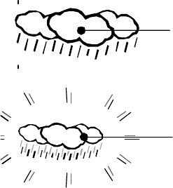
Light Rain/Heavy Rain Indicator
The wireless rain gauge features 2 rain level indicators: Light
Rain and Heavy Rain.
Light Rain: Indicated by 3 clouds and
rain with no animation.
The Light Rain icon will appear if any rain
is registered over the past 10 minutes.
Heavy Rain: Indicated by 3 clouds with
animated rain.
The Heavy Rain Icon will appear if more
than 10 counts (0.2”) have been
registered over the past 10 minutes.
Low Battery Indicators (RX & TX)
• RX: Indicates the receiver battery is low.
• TX: Indicates the rain gauge battery is low.
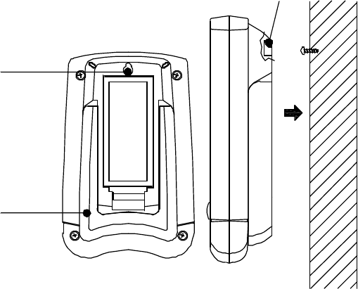
MOUNTING
Positioning the Receiver:
The Receiver can be positioned on a flat surface or on a wall.
8
Foldout Table Stand
The foldout table stand is located on the backside of the Receiver.
Carefully pull out the stand and place the Receiver in the desired
location.
Wall Mounting
Place a screw in the desired location leaving the head extended
about ¼” from the wall. Hang the Receiver on the screw ensuring
that the Receiver locks into place.
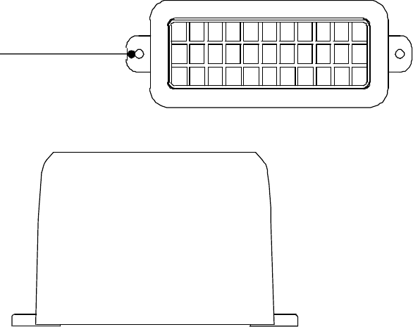
Positioning the Rain Gauge
Position the connected rain gauge outdoor to collect rainfall data.
Ensure that the rain gauge is placed in a secure and flat location
where it can properly collect properly rain quantity without
obstruction. Ensure also that the rain gauge is securely mounted
at the appropriate location otherwise it may not transmit accurate
rainfall data.
The rain gauge must be level to transmit correct readings. It is
recommended to mount the rain gauge 3 feet or higher off of the
ground. Screw the rain gauge down snugly in the holes provided
(but not too tight as this will affect the accuracy of the gauge).
Hanging Hole
Hanging Hole
Table Stand
9
MAINTENANCE
• Avoid placing the units in locations prone to extreme
temperatures, vibration and shock since these may cause
damage and inaccurate readings.
• When cleaning the display and casing of the Wireless Rain
Gauge, use a soft damp cloth only. Do not use solvents or
scouring agents as they may mark the casing and LCD.
• Do not submerge the Wireless Rain Gauge in water.
• Immediately remove all low powered batteries to avoid leakage
and damage. Replace only with new batteries of the
recommended type.
• Please do not make any attempt to make any repairs to the
units. Return them to their original point of purchase for repair
by qualified personnel. Opening and tampering with the units
will invalidate the warranty.
Holes
for screws
Top View
Side Vie
w
10
SPECIFICATIONS
Rainfall
Rainfall Alarm User defined from 0.05” to 4.00”
over 24 hour period
Rainfall Range
0.00” to 199.99” (total)
(“OFL” displayed if outside this
range) 0.00” to 9.98” “(24H))
(“OFL” displayed if outside this
range, or if rainfall recorded is
greater than 5.00” within 2
hours)
Unit Display Inch
Transmission Range 330 Feet
Transmission 915 MHz, updating every 6
seconds
Power Supply:
Receiver: 2 x AAA, IEC LR3, 1.5V.
Rain Gauge: 2 x AAA, IEC LR3, 1.5V.
Battery life cycle: Approximately 36 months.
Recommended battery type: Alkaline.
Dimensions (H x L x W)
Receiver 3.85” x 2.45” x .95”
Rain Gauge: 5.67” x 2.15” x 3.46”
LIABILITY DISCLAIMER
• The manufacturer and supplier cannot accept any
responsibility for any incorrect readings and any
consequences occurring should an inaccurate reading take
place.
• This product is not to be used for medical purposes or for
public information.
• This product is designed for strict home use as an indication of
rain quantities and is not 100% accurate. Readouts given by
this product should be taken only as an indication and not as
being totally accurate.
• The specifications of this product may change without prior
notice.
11
• This product is not a toy. Keep out of the reach of children.
• No part of this manual may be reproduced without written
consent of the manufacturer.
WARRANTY INFORMATION
La Crosse Technology, Ltd provides a 1-year limited warranty on this product against
manufacturing defects in materials and workmanship.
This limited warranty begins on the original date of purchase, is valid only on products purchased
and used in North America and only to the original purchaser of this product. To receive warranty
service, the purchaser must contact La Crosse Technology, Ltd for problem determination and
service procedures. Warranty service can only be performed by a La Crosse Technology, Ltd
authorized service center. The original dated bill of sale must be presented upon request as proof
of purchase to La Crosse Technology, Ltd or La Crosse Technology, Ltd’s authorized service
center.
La Crosse Technology, Ltd will repair or replace this product, at our option and at no charge as
stipulated herein, with new or reconditioned parts or products if found to be defective during the
limited warranty period specified above. All replaced parts and products become the property of La
Crosse Technology, Ltd and must be returned to La Crosse Technology, Ltd. Replacement parts
and products assume the remaining original warranty, or ninety (90) days, whichever is longer. La
Crosse Technology, Ltd will pay all expenses for labor and materials for all repairs covered by this
warranty. If necessary repairs are not covered by this warranty, or if a product is examined which is
not in need or repair, you will be charged for the repairs or examination. The owner must pay any
shipping charges incurred in getting your La Crosse Technology, Ltd product to a La Crosse
Technology, Ltd authorized service center. La Crosse Technology, Ltd will pay ground return
shipping charges to the owner of the product to a USA address only.
Your La Crosse Technology, Ltd warranty covers all defects in material and workmanship with the
following specified exceptions: (1) damage caused by accident, unreasonable use or neglect
(including the lack of reasonable and necessary maintenance); (2) damage occurring during
shipment (claims must be presented to the carrier); (3) damage to, or deterioration of, any
accessory or decorative surface; (4) damage resulting from failure to follow instructions contained in
your owner’s manual; (5) damage resulting from the performance of repairs or alterations by
someone other than an authorized La Crosse Technology, Ltd authorized service center; (6) units
used for other than home use (7) applications and uses that this product was not intended or (8) the
products inability to receive a signal due to any source of interference.. This warranty covers only
actual defects within the product itself, and does not cover the cost of installation or removal from a
fixed installation, normal set-up or adjustments, claims based on misrepresentation by the seller or
performance variations resulting from installation-related circumstances.
LA CROSSE TECHNOLOGY, LTD WILL NOT ASSUME LIABILITY FOR INCIDENTAL,
CONSEQUENTIAL, PUNITIVE, OR OTHER SIMILAR DAMAGES ASSOCIATED WITH
THE OPERATION OR MALFUNCTION OF THIS PRODUCT. THIS PRODUCT IS NOT
TO BE USED FOR MEDICAL PURPOSES OR FOR PUBLIC INFORMATION. THIS
PRODUCT IS NOT A TOY. KEEP OUT OF CHILDREN’S REACH.
This warranty gives you specific legal rights. You may also have other rights specific to
your State. Some States do no allow the exclusion of consequential or incidental
damages therefore the above exclusion of limitation may not apply to you.
For warranty work, technical support, or information contact:
La Crosse Technology, Ltd
190 Main Street
La Crescent, MN 55947

12
Phone: 507.895.7095
Fax: 507.895.2820
e-mail:
support@lacrossetechnology.com
(warranty work)
sales@lacrossetechnology.com
(information on other products)
web:
www.lacrossetechnology.com
Questions? Please see instruction video at:
www.lacrossetechnology.info/9004
All rights reserved. This handbook must not be reproduced in any form, even in excerpts, or duplicated or
processed using electronic, mechanical or chemical procedures without written permission of the publisher.
This handbook may contain mistakes and printing errors. The information in this handbook is regularly checked
and corrections made in the next issue. We accept no liability for technical mistakes or printing errors, or their
consequences.
All trademarks and patents are acknowledged.
FCC ID: TX FCC ID: OMO-TX24U
THIS DEVICE COMPLIES WITH PART 15 OF THE FCC RULES. OPERATION IS SUBJECT TO
THE FOLLOWING TWO CONDITIONS:
1. THIS DEVICE MAY NOT CAUSE HARMFUL INTERFERENCE, AND
2. THIS DEVICE MUST ACCEPT INTERFERENCE RECEIVED, INCLUDING INTERFERENCE
THAT MAY CAUSE UNDESIRED OPERATION.
RFExposure mobil:
The internal / external antennas used for this mobile transmitter must provide a separation
distance of at least 20 cm from all persons and must not be co-located or operating in
conjunction with any other antenna or transmitter."
Statement according to FCC part 15.21:
Modifications not expressly approved by this company could void the user's authority to
operate the equipment.
Statement according to FCC part 15.105:
NOTE: This equipment has been tested and found to comply with the limits for a Class B
digital device, pursuant to Part 15 of the FCC Rules. These limits are designed to provide
reasonable protection against harmful interference in a residential installation. This equipment
generates, uses and can radiate radio frequency energy and, if not installed and used in
accordance with the instructions, may cause harmful interference to radio communications.
However, there is no guarantee that interference will not occur in a particular installation. If
this equipment does cause harmful interference to radio or television reception, which can be
determined by turning the equipment off and on, the user is encouraged to try to correct the
interference by one or more of the following measures:
• Reorient or relocate the receiving antenna.
• Increase the separation between the equipment and receiver.
• Connect the equipment into an outlet on a circuit different from that to which the receiver is
connected.
• Consult the dealer or an experienced radio/TV technician for help