Lab Partners Associates PW2-003 Remote Control Transmitter User Manual LPF058 Final
Lab Partners Associates Inc Remote Control Transmitter LPF058 Final
Exhibit D Users Manual per 2 1033 b3
Owner’s Manual
www.PocketWizard.com
2
3
TABLE OF CONTENTS
Congratulations . . . . . . . . . . . . . . . . . . . . . . . . . . . . . . . . . . . . . . 3
Key Features . . . . . . . . . . . . . . . . . . . . . . . . . . . . . . . . . . . . . . . . 3
Part Reference (Package Contents) . . . . . . . . . . . . . . . . . . . . . . . 4
Batteries . . . . . . . . . . . . . . . . . . . . . . . . . . . . . . . . . . . . . . . . . . . . 5
Mounting . . . . . . . . . . . . . . . . . . . . . . . . . . . . . . . . . . . . . . . . . . . 5
Setup for Remote Flash Triggering . . . . . . . . . . . . . . . . . . . . . . . . 6
Camera Setup . . . . . . . . . . . . . . . . . . . . . . . . . . . . . . . . . . . 6
Remote Flash Setup . . . . . . . . . . . . . . . . . . . . . . . . . . . . . . . 6
Triggering . . . . . . . . . . . . . . . . . . . . . . . . . . . . . . . . . . . . . . . 6
Connecting a Flash to the
Camera’s Transceiver (Local Flash) . . . . . . . . . . . . . . . . . . . 7
Local TTL Flash . . . . . . . . . . . . . . . . . . . . . . . . . . . . . . . . . . 7
Triggering A Remote Camera . . . . . . . . . . . . . . . . . . . . . . . . . . . . 8
Relay Mode . . . . . . . . . . . . . . . . . . . . . . . . . . . . . . . . . . . . . . . . . 8
Relay Mode Setup . . . . . . . . . . . . . . . . . . . . . . . . . . . . . . . . 9
Turning Off Relay Mode . . . . . . . . . . . . . . . . . . . . . . . . . . . . 9
Sustaining High Performance . . . . . . . . . . . . . . . . . . . . . . . . . . 10
Troubleshooting . . . . . . . . . . . . . . . . . . . . . . . . . . . . . . . . . . . . . 10
Troubleshooting Chart . . . . . . . . . . . . . . . . . . . . . . . . . . . . 11
Notes . . . . . . . . . . . . . . . . . . . . . . . . . . . . . . . . . . . . . . . . . . . . . 12
Technical Information . . . . . . . . . . . . . . . . . . . . . . . . . . . . . . . . 13
“The FCC Wants You To Know” . . . . . . . . . . . . . . . . . . . . . . . . . 14
To find the correct PocketWizard brand cables for your
flash and cameras, and to experience other products like
the MultiMAX, please visit www.PocketWizard.com.

2
3
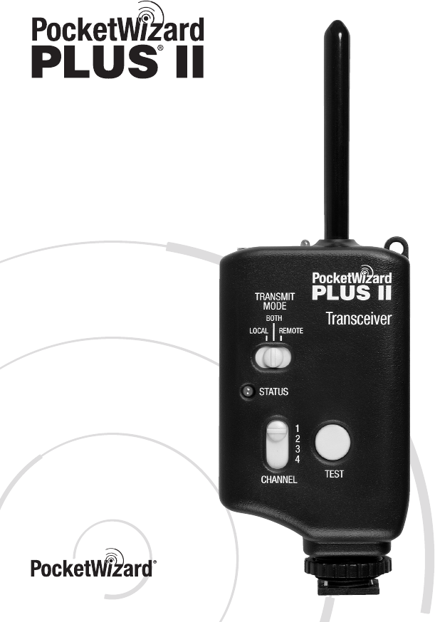
Congratulations on your purchase of the new
PocketWizard Plus® II Transceiver, a high performance Digital
Wireless Radio Slave and Remote Triggering System. The Plus II
features advanced auto-sensing intelligence to automatically send
or receive PocketWizard radio signals based simply on how it is
connected. PocketWizards are the most technologically advanced
microprocessor-controlled radio triggers for flash and cameras.
Using carefully engineered filtering and digital signaling technology,
PocketWizards reject ambient radio noise and have a wide dynamic
range enabling high performance, consistency, and reliability for all
types of remote photography.
The Plus II Transceiver is compatible with all PocketWizard radio systems.
PocketWizard Plus II Key Features
Auto-Sensing Transceiver – Automatically transmits or receives based on
connections. No Tx/Rx switches. No sorting out Transmitters and Receivers.
Simply make connections and start working sooner with near-zero configuration time.
Auto-Relay – Easily trigger a remote camera in sync with a distant remote flash.
Put a camera where you can’t be and have remote lighting at the same time.
Expand your coverage and increase your creativity.
Fast FPS – Trigger cameras or flash units up to 12 frames per second.
4 Sixteen-Bit Digitally Coded Channels – Create multiple setups or work
exclusively at events with other photographers without interference.
1600 Foot Range – Long PocketWizard range equals increased performance and
reliability even when working at average photographic distances. Our enhanced
range provides best-in-class remote performance for all types of photography.
Fast Sync Speeds – Compatible with most cameras’ fastest X-Sync speeds including:
— 1/250 Focal Plane Shutters
— 1/500 Leaf Shutters
Locking Hot Shoe Mount – Secure mounting. Several other mounting methods included.
4
5
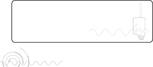
POCKETWIZARD PLUS II PART REFERENCE
Lanyard Loop
Flash
Camera / Flash
Status LED
On/Off
Switch
Locking Hot
Shoe Mount
Battery
Door
1
/
4 - 20
Mount
Battery Door Latch
Flexible Antenna
Status LED
TRANSMIT MODE
Local/Both/Remote
AC
Power
Test
Button
Channel
Selection
If you purchased a single Plus II Transceiver then your box contains 1 each of the above
items, except where noted. The Plus II Transceiver Kit contains 2 each of the above items,
except where noted. This manual and a warranty information card are also included.
PC1 Cable
For use with a camera’s PC terminal
(only 1 included with Kit)
AA Batteries
(IEC-LR6)
Lanyard
VELCRO®
Adhesive Hook
and Loop Fasteners
4
5
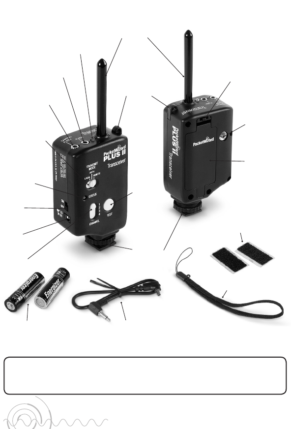
For attaching to
flashes, brackets,
cameras, etc.
See NOTE 2.
VELCRO®
For tripods,
mounting arms,
isolation bars,
brackets, etc.
1/4-20 Mount
For mounting on
a bracket shoe, cold
or dead shoe, etc.
For hanging from a
light stand, flash handle,
tripod knob, belt, etc.
Lanyard
Shoe Mount
BATTERIES
CAUTION: Turn OFF your equipment (PocketWizard units,
electronic flash units, cameras, etc.) before making connections
or changing batteries.
Install 2 fresh AA (IEC:LR6) batteries into the Plus II Transceiver.
Make sure to note proper polarity. Alkaline batteries are recommended.
Rechargeable batteries will also work, though operation time may be reduced.
When the STATUS LEDs stop blinking, it is time to change the batteries.
Battery life is approximately 60 hours under typical use.
See NOTE 1 for more battery information.
WARNING – To avoid battery leakage, follow these guidelines:
• Always remove the batteries when the unit is not in use for extended periods of time,
or during shipping or long distance travel.
• Never mix old and new batteries. Always use a fresh pair of matched batteries.
• Always change batteries promptly at the first indication of low battery operation.
• Do not use or leave the unit in extreme temperature or humidity situations.
See “Technical Information” for normal operating and storage temperatures.
MOUNTING
Mount a remote Plus II Transceiver using any of the included methods.
See “Sustaining High Performance” for more mounting information.
6
7
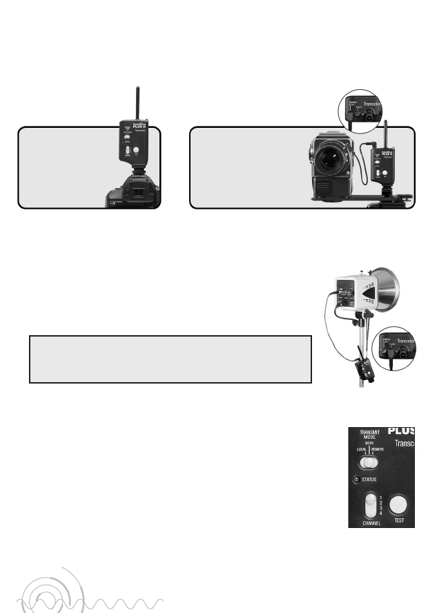
SETUP FOR REMOTE FLASH TRIGGERING
Camera Setup
Connect a Plus II Transceiver to the camera using one of the following methods:
Remote Flash Setup
Connect the Plus II Transceiver’s FLASH port to the flash unit’s sync terminal using:
a) the correct PocketWizard flash sync cable for best results.
- or -
b) your flash unit’s original sync cable and a PC female adapter
(PocketWizard part number MPCF (804-605)).
You may have as many remote Plus II Transceivers on the same
channel as you would like. Connecting 2 flashes to a single
Plus II Transceiver will not work. See NOTE 3.
Triggering
1. Turn on both Plus II Transceivers, and turn on the camera and flash.
2. On both Plus II Transceivers make sure that:
• The STATUS LEDs on each Plus II Transceiver blink every
few seconds.
• The same channel is selected using the CHANNEL slide switch.
• The TRANSMIT MODE switch is set to BOTH (middle position
which is default operation).
3. Press the TEST button on the camera’s Plus II Transceiver to
confirm that the remote flash triggers.
4. Begin triggering normally.
or
Slide the Plus II
Transceiver into
the camera’s hot
shoe and tighten
the hot shoe nut.
Option 1
Connect the PC1 sync
cable (included) from
the camera’s PC terminal
to the port labeled
CAMERA / FLASH.
Option 2
Shown with
default settings.
6
7
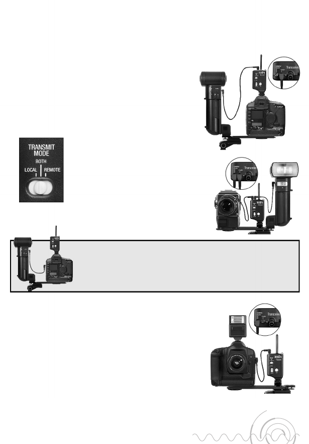
Connecting a Flash to the Camera’s Transceiver (Local Flash)
A LOCAL flash is usually a non-TTL flash that is mounted on or near the camera,
for example on the camera’s bracket. It can be triggered from the camera’s
Plus II Transceiver ensuring perfect synchronization with remote flashes.
See below for using a LOCAL TTL FLASH.
1. On the camera’s Plus II Transceiver, connect the
FLASH port to your local flash unit’s sync terminal.
Use a PocketWizard flash sync cable for best results.
2. Use the TRANSMIT MODE switch to creatively
select which flashes will trigger:
• LOCAL = Only the flash connected to
the camera’s Transceiver will trigger.
Remote PocketWizards will not trigger.
• BOTH (Default) = Both the local and remote
flashes will trigger in perfect synchronization.
• REMOTE = Only the flashes connected
to remote PocketWizards will trigger.
The flash connected to the camera’s
Plus II Transceiver will not trigger.
Local TTL Flash
Plus II Transceivers do not transmit TTL information.
You can use a TTL flash directly connected to your
camera and have remote flashes (not in TTL mode)
triggered by PocketWizards.
See NOTE 4 for important timing information.
To operate in this manner, simply connect the
Transceiver’s CAMERA / FLASH port to your camera’s
PC terminal and make all other camera to TTL flash connections normally.
Alternate Connection Method: You may connect a local flash directly
to your camera’s PC terminal. In this case, the local flash will always
trigger regardless of the position of the TRANSMIT MODE switch.
See NOTE 4 for important timing information.
8
9
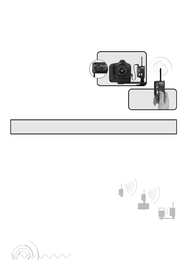
TRIGGERING A REMOTE CAMERA
A Plus II Transceiver, paired with any PocketWizard Transmitter, can be used to
trigger a remote camera. The camera needs to have an electronic shutter release
connection and have a compatible PocketWizard motor drive cable available.
Please visit www.PocketWizard.com to determine the correct motor drive cable.
Basic Remote Camera Setup
1. Connect a Plus II Transceiver’s
CAMERA / FLASH port to the motor
drive port of the camera using a
PocketWizard motor drive cable.
2. Make sure the Plus II Transceiver
and the hand-held PocketWizard are
set to the same channel and turned on.
3. Press the TEST button on the hand-held
PocketWizard to trigger the remote camera.
You can have a flash directly connected to the remote camera. Connecting a flash to the
FLASH port of the Plus II Transceiver will not work in this setup. See NOTE 3.
RELAY MODE
You can trigger a remote flash in sync with your remote camera. This is called
relay mode and requires only 3 PocketWizards. Here is how it works:
• You press TEST on a PocketWizard that you are holding in your hands.
• The Plus II Transceiver connected to your remote
camera receives the signal and triggers your camera.
• The Plus II Transceiver switches to transmit mode,
one channel higher, and waits for the camera to
provide a sync pulse.
• The PocketWizard connected to your flash receives
the camera’s sync pulse and triggers your flash.
Hand Held
Trigger
Remote Camera
8
9
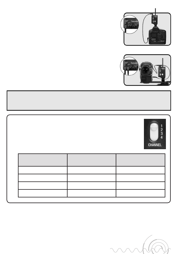
Relay Mode Setup
1. Set the master triggering PocketWizard
(the one in your hands) to Channel 1.
2. Set the Plus II Transceiver (the one for your remote
camera) to Channel 1 and set TRANSMIT MODE to BOTH.
3. Connect the Plus II Transceiver’s CAMERA / FLASH port to
the motor drive port of the camera.
4. Slide the Plus II Transceiver into your camera’s hot shoe.
5. Set the PocketWizard for your remote flash to Channel 2.
6. Connect your remote flash to its PocketWizard normally.
7. Turn everything on, then press and release TEST on the
PocketWizard in your hands to begin the sequence.
If you are using a camera with no hot shoe, or the hot shoe cannot be used, then connect
the Plus II in this manner: Connect the camera’s motor drive cable to the FLASH port.
Connect the camera’s PC sync terminal to the CAMERA / FLASH port.
You can use different channels to perform the relay function. The
master triggering PocketWizard (usually the one held in your hand)
and the Plus II Transceiver connected to your remote camera need
to be on the same channel. The PocketWizard connected to your
remote flash needs to be set one channel higher.
If master trigger
PocketWizard is set to:
Set the remote camera’s
Plus II Transceiver to:
Set the remote flash’s
PocketWizard to:
112
223
334
441
CHANNEL
Turning Off Relay Mode
If you want to trigger a remote camera and have the Plus II mounted in the
camera’s hot shoe, but you do not want the relay sequence to happen, simply
set the TRANSMIT MODE switch to LOCAL on the unit in the camera’s shoe.
See NOTE 5 for more information on relay triggering.
Using Hot Shoe
Without Hot Shoe
10
11
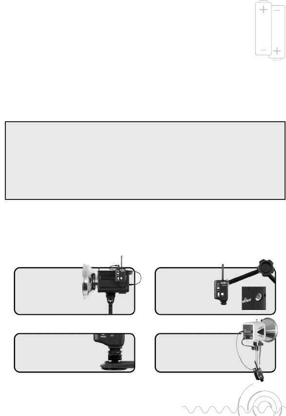
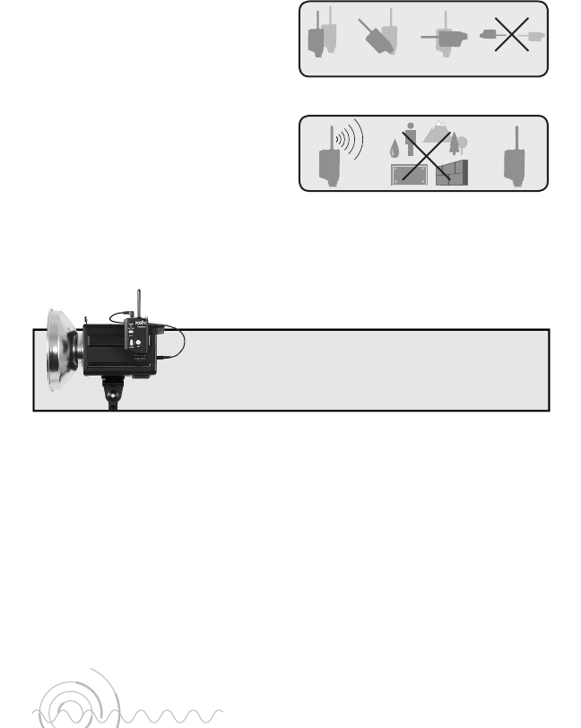
SUSTAINING HIGH PERFORMANCE
Long distance performance from
your PocketWizards depends on the
orientation and position of the units.
Whenever possible, try to maintain
a line of sight between the units and
keep the antennas parallel. Make sure
they are not near any large metal,
concrete, or high water-content
objects. People and trees are mostly
water! Make sure they are not
blocked by these objects or by hills.
Maintain a 12" or greater distance between antennas. Avoid direct antenna
contact with anything metallic. “Dead spots” are caused by a number of things,
but the solution is almost always the same: move the unit a few inches or feet
away from the problem area.
Mount the remote PocketWizard so that the antenna is
completely above the top edge of the flash pack and away
from any metal (light modifiers, stands, etc.).
TROUBLESHOOTING
First follow the steps below, and then consult the table on the following page.
1. Turn the units off, verify fresh batteries are in use, and turn the units back on.
2. Double check all connections.
3. Make sure the units are set to the same channel number.
4. Set the Transmit Mode switch to the BOTH position.
5. Press TEST on every unit and verify proper operation.
Positioning
PoorAcceptable
Best Worst
Blocking Signal
Mounting
suggestion.

10
11
Troubleshooting Chart
Problem Solution
When I press TEST or
trigger the camera, the
remotes do not trigger.
• See “Sustaining High Performance” earlier for
radio information.
• Set the TRANSMIT MODE switch to BOTH.
When I press the
TEST button, the flash
or camera directly
connected to the unit
does not trigger.
• Verify that the remote equipment is functional when not
connected to the PocketWizard. Try a different flash or camera.
• Double check all connections. Eliminate adapters if possible.
Make sure the cable is properly connected to the correct port
on the flash or camera. If triggering a flash with a household
style sync terminal, try reversing the household connection
(correct the polarity).
• Try connecting to the other port on the PocketWizard unit.
Either port can trigger most cameras or flashes. Each port has
slightly different triggering characteristics that may be more or
less compatible with your equipment.
• Verify that the flash being triggered has a sync voltage that is
compatible with your PocketWizard (see “Technical Information”).
• A remote camera cannot be triggered via its PC terminal or hot
shoe. Get a motor drive cable.
• Try replacing the cable. Use PocketWizard brand cables.
The STATUS LED does
not blink when the
power switch is on.
• Try new AA alkaline batteries. See the “Batteries” section for
more information.
• If the unit has been left on but not triggered for ~40 hours,
then it has shut down to prevent potential battery leakage.
Turn the unit off and back on again or change the batteries.
• Double check the power source and connections if you are
using an AC adapter.
The STATUS LEDs
are on continuously
(do not blink or blink
rapidly) and no buttons
are being pressed.
• Check for a stuck TEST button on all units. Turn each unit off
and back on again to isolate the source of the problem.
• Remove the unit from the camera’s hot shoe and/or unplug
and reconnect any connecting cables.
• Try switching all remote connections to the FLASH port
rather than the CAMERA / FLASH port.
If the above troubleshooting techniques did not resolve your
issue, visit www.PocketWizard.com for more information.

12
13
NOTES
Note 1 – The Plus II Transceiver shuts down after approximately 40 hours if it
receives no triggers, or if the combined battery voltage drops below 1.7 volts.
This is to protect against severe battery depletion which may lead to leakage.
Power the unit off and back on again, or replace the batteries, for normal use. If
you need the unit to remain powered for more than 40 hours, get a PocketWizard
AC Adapter (part number PW-AC-2 (804-105)) or a compatible adapter.
Note 2 – VELCRO® Brand Fasteners are included to provide a convenient means
of mounting the unit in a variety of places. Attach as desired being careful to
not obscure controls or function. Recommended mounting locations are the
side of the unit or the area below the 1/4-20 mount. The battery door is not a
recommended mounting location as damage to the battery door could occur
when dismounting the unit.
Note 3 – If there is any cable connected to the FLASH Port on a Plus II, then the
CAMERA / FLASH Port is switched to input mode only. If you connect 1 flash
to each port of the Plus II, then only the flash connected to the FLASH port will
trigger. Attempting to connect 2 flashes to the FLASH port can be dangerous.
Different flashes can have very different sync voltages. Connecting them together
could cause damage to the flashes, and they may not trigger. 2 identical flashes
with known identical sync voltages may work when connected together, but
operation is not guaranteed to be risk free.
Note 4 – There is a 1/2000 second delay when triggering via PocketWizard
radios. This means your radio remote flashes will trigger 1/2000 second after
your camera connected flash triggers. For very fast moving objects this may
result in image streaking or 2 distinct flash moments on the same image
(double exposures).
Note 5 – If you press and *hold* the TEST button on the unit in your hands,
and you are using a fast shutter speed like 1/200 or faster, then you may cause
interference for the remote flash unit. It may miss the flash sync pulse from
the camera. Press and immediately release the TEST button to help avoid this
situation. If you are attempting to perform a long exposure or a motor drive
multi-frame burst, then you may need to consider our MultiMAX product for
enhanced relay functionality.

12
13
TECHNICAL INFORMATION
Frequency: 344.04 Megahertz
Transmit output power: Less than 0.001 watt (1/1000 of a watt or 1 milliwatt)
Minimum receive Contact Time: 80 milliseconds
Maximum Frames Per Second: 12
Top Ports: 3.5mm (1/8") mono miniphone
CAMERA / FLASH Port Voltage Handling: up to 100 Volts
FLASH Port Voltage Handling: up to 200 Volts
CAMERA / FLASH = center positive; FLASH = non-polarized
Both ports are current limited: 4 Amp peak, 250 millamp continuous
CAMERA / FLASH Port and hot shoe mount voltage present: 3.3 Volts DC.
A camera is protected from a flash connected to either port.
AC Adapter jack: 3V DC 200mA (unregulated), Center Positive
Male plug connector required: 1.3mm ID, 3.4mm OD, 1cm long
Body Dimensions: 1.4" deep x 2.1" wide x 4" tall
Antenna: 2.4" tall, 0.3" diameter
Weight: Less than 5 ounces with alkaline batteries
Operating temperature: above -15° C (5° F) and below 50° C (120° F)
Storage temperature, without batteries: above -30° C (-22° F) and
below 85° C (185° F)
14
15
THE FCC WANTS YOU TO KNOW:
WARNING: Changes or modifications to this unit not expressly approved by the party
responsible for compliance could void the user’s authority to operate the equipment.
NOTE: This equipment has been tested and found to comply with the limits for a Class B
digital device, pursuant to Part 15 of the FCC rules. These limits are designed to provide
reasonable protection against harmful interference in a residential installation. This
equipment generates, uses, and can radiate radio frequency energy, and, if not installed
and used in accordance with the instructions, may cause harmful interference to radio
communications.
However, there is no guarantee that interference will not occur in a particular installation. If
this equipment does cause harmful interference to radio or television reception, which can
be determined by turning the equipment off and on, the user is encouraged to try to correct
the interference by one or more of the following measures:
1. Reorient or relocate the receiving antenna.
2. Increase the separation between the equipment and the receiver.
3. Consult the dealer or an experienced radio or television technician for help.
This device complies with Part 15 of the FCC rules and also with RSS-210 of Industry &
Science Canada. Operation is subject to the following two conditions: (1) This device may
not cause harmful interference, and (2) This device must accept any interference received,
including interference that may cause undesired operation.
Transceiver FCC ID Number: KDS-PW2-003
Transceiver CANADA IC: 2170A-PW003
14
15

Plus II, Manual Revision 1.0 (LPF058)
For more information about using
your PocketWizard product visit:
www.PocketWizard.com