LabelZone Zebra Zd500 ZD500™ Series Users Guide (en) User Manual
Zd500 Userguide ZD500_UserGuide
Zebra-Thermal-Transfer-Printer-Zd500-Users-Manual-342274 zebra-thermal-transfer-printer-zd500-users-manual-342274
ZD500 to the manual 29970017-1100-4b98-8178-88d9a07dd443
2017-09-13
User Manual: LabelZone Zebra Zd500
Open the PDF directly: View PDF ![]() .
.
Page Count: 160 [warning: Documents this large are best viewed by clicking the View PDF Link!]
- Contents
- Introduction
- Setup
- Select a Location for the Printer
- Attaching Power
- Preparing and Handling Media
- Setting the Printer Menu and Report Display Language
- Loading Roll Media
- Loading Transfer Ribbon
- Test Printing with Configuration Report Printouts
- Connecting your Printer to a Computer
- ZebraNet® Internal Wireless Print Server Option
- Configure Using the Connectivity Wizard
- Bluetooth Option Configuration
- After Your Printer is Connected
- Printer Configuration
- Print Operations
- Determining Printer Configuration
- Types of Media
- Media Loading
- Ribbon Overview
- Replacing Supplies
- Adjusting the Print Width
- Adjusting the Print Quality
- Media Sensing
- Using the Movable Black Mark Sensor
- Printing on Fan-Fold Media
- Printing with Externally Mounted Roll Media
- Sending Files to the Printer
- Fonts and Your Printer
- Printer Options
- Maintenance
- Troubleshooting
- Appendix: Interface Wiring
- Appendix: Dimensions

User’s Guide
Thermal Transfer Printer
ZD500 Series™
P1062653-002 Rev. A

ii
P1062653-002 Rev. A ZD500 Series™ Thermal Transfer Printer User’s Guide 1/16/2014
© 2013 ZIH Corp. The copyrights in this manual and the software and/or firmware in the
label printer and accessories described therein are owned by ZIH Corp. Unauthorized
reproduction of this manual or the software and/or firmware in the label printer may result in
imprisonment of up to one year and fines of up to $10,000 (17 U.S.C.506). Copyright violators
may be subject to civil liability.
This product may contain ZPL®, ZPL II®, and ZebraLink™ programs; Element Energy
Equalizer® Circuit; E3®; and Monotype Imaging fonts. Software © ZIH Corp. All rights
reserved worldwide.
ZD500 Series, ZD500R, ZebraLink and all product names and numbers are trademarks, and
Zebra, the Zebra logo, ZPL, ZPL II, Element Energy Equalizer Circuit, and E3 Circuit are
registered trademarks of ZIH Corp. All rights reserved worldwide.
All other brand names, product names, or trademarks belong to their respective holders.
For additional copyright and trademark information, please see “Copyright” on the Zebra
website.
www.zebra.com/copyright
Proprietary Statement This manual contains proprietary information of Zebra
Technologies Corporation and its subsidiaries (“Zebra Technologies”). It is intended solely for
the information and use of parties operating and maintaining the equipment described herein.
Such proprietary information may not be used, reproduced, or disclosed to any other parties
for any other purpose without the express, written permission of Zebra Technologies.
Product Improvements Continuous improvement of products is a policy of Zebra
Technologies. All specifications and designs are subject to change without notice.
Liability Disclaimer Zebra Technologies takes steps to ensure that its published
Engineering specifications and manuals are correct; however, errors do occur. Zebra
Technologies reserves the right to correct any such errors and disclaims liability resulting
therefrom.
Limitation of Liability In no event shall Zebra Technologies or anyone else involved in the
creation, production, or delivery of the accompanying product (including hardware and
software) be liable for any damages whatsoever (including, without limitation, consequential
damages including loss of business profits, business interruption, or loss of business
information) arising out of the use of, the results of use of, or inability to use such product,
even if Zebra Technologies has been advised of the possibility of such damages. Some
jurisdictions do not allow the exclusion or limitation of incidental or consequential damages,
so the above limitation or exclusion may not apply to you.

iii
1/16/2014 ZD500 Series™ TThermal Transfer Printer User’s Guide P1062653-002Rev. A
Compliance and Regulatory Statements
FCC Compliance Statement (USA)
This device complies with Part 15 rules. Operation is subject to the following two conditions:
1. This device may not cause harmful interference, and
2. This device must accept any interference received, including interference that may cause
undesired operation.
This equipment has been tested and found to comply with the limits for Class B Digital
Devices, pursuant to Part 15 of the FCC Rules. These limits are designed to provide reasonable
protection against harmful interference when the equipment is operated in a residential
environment. This equipment generates, uses, and can radiate radio frequency energy and, if
not installed and used in accordance with the product manuals, may cause harmful interference
to radio communications. However, there is no guarantee that interference will not occur in a
particular installation. If this equipment does cause harmful interference to radio or television
reception, the user is encouraged to do one or more of the following measures:
• Reorient or relocate the receiving antenna.
• Increase the separation between the equipment and receiver.
• Connect the equipment into an outlet on a circuit different from that to which the receiver
is connected.
• Consult the dealer or an experienced RF service technician for help.
Important •
1. The radio must be installed with a minimum 20 cm separation between the user and the
antenna.
2. The radio must not be co-located or used in simultaneous transmitting condition with
another radio.
3. The host system shall have a label to indicate that the system contains a certified module.
An example is “Contains FCC ID : I28MD-EXLAN11N , IC ID: 3798B-EXLAN11N”.
4. The radio is for indoor use only in the 5150-5250 GHz frequency range.
The user is cautioned that any changes or modifications not expressly approved by Zebra
Technologies could void the user’s authority to operate the equipment. To ensure compliance,
this printer must be used with fully shielded communication cables.
Mexico — NOM-121-SCT1-2009
Este equipo ha sido diseñado para operar con las antenas que enseguida se enlistan y para una
ganancia máxima de antena de [x] dB. El uso con este equipo de antenas no incluidas en esta
lista o que tengan una ganancia mayor que [x] dB quedan prohibidas. La impedancia requerida
de la antena es de [y] ohms.
auden - p/n 220370-09
• Gain = 2.77dbi @ 2.4 GHz
• Gain = 2.69 - 3.19dBi @ 5 GHz
• Impedance = 50 ohms

iv
P1062653-002 Rev. A ZD500 Series™ Thermal Transfer PrinterUser’s Guide 1/16/2014
Canadian DOC Compliance Statement
Cet appareil numérique de la classe B est conforme à la norme NMB-003 du Canada.
This Class B digital apparatus complies with Canadian ICES-003.
Industry Canada (IC) Warning
Le présent appareil est conforme aux CNR d’Industrie Canada applicables aux appareils radio
exempts de licence. L’exploitation est autorisée aux deux conditions suivantes : (1) l’appareil
ne doit pas produire de brouillage, et (2) l’utilisateur de l’appareil doit accepter tout brouillage
radioélectrique subi, même si le brouillage est susceptible d’en compromettre le
fonctionnement.
This device complies with Industry Canada license-exempt RSS standard(s). Operation is
subject to the following two conditions: 1) This device may not cause interference., 2) This
device must accept any interference, including interference that may cause undesired operation
of the device.
Brasil — Aviso da Anatel
Este equipamento opera em caráter secundário, isto é, não tem direito a proteção contra
interferência prejudicial, mesmo de estações do mesmo tipo, e não pode causar interferência a
sistemas operando em caráter primário.
“Este produto está homologado pela ANATEL, de acordo com os procedimentos
regulamentados pela Resolução 242/2000, e atende aos requisitos técnicos aplicados”
Para maiores informações, consulte o site da ANATEL www.anatel.gov.br
This equipment's operation is of a secondary character; that is, it doesn't have the right to
protection against damaging interference, even from stations of the same type, nor can it cause
interference to systems with a primary operating character.
Este produto utiliza internamente o modulo de RF M6E- micro numero de homologação pela
ANATEL 3059-13-8108 e o modulo WYSBMVGXB numero de homologação pela ANATEL
3825-13-9965
Este equipamento opera em caráter secundário, isto é, não tem direito a proteção contra
interferência prejudicial, mesmo de estações do mesmo tipo, e não pode causar interferência a
sistemas operando em caráter primário.
Japan Restricted Frequencies
この周波数帯は 5.725 5.825 GHz の日本で利用できるされません。
For 5.725 - 5.825 GHz, this frequency band will not be available in Japan.
v
1/16/2014 ZD500 Series™ TThermal Transfer Printer User’s Guide P1062653-002Rev. A
Taiwan Restricted Frequencies
5.15-5.25 GHz, 該頻段將在臺灣不可用。
For 5.15 - 5.25 GHz, this frequency band will not be available in Taiwan.
Korean Compliance Statement
이 기기는 가정용 (B 급 ) 전자파 적합기기 로서 주로 가정에서 사용하는 것을 목적으로
하며 , 모든 지역에서 사용할 수 있습니다 .
The equipment is for home use (Class B) and has acquired electromagnetic conformity
registration, so it can be used not only in residential area but other areas as well.
This radio device is not allowed to be used for human safety since it has possibility of radio
interference during operation.
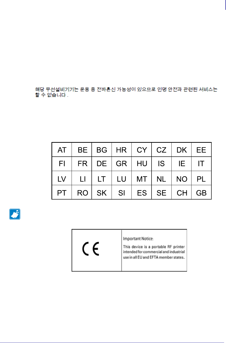
European Regulatory Information
Note • Member states in the EU with restrictive use for this device are crossed out. This
device is also authorized for use in all EFTA member states (CH, IS, LI, NO).

vi
P1062653-002 Rev. A ZD500 Series™ Thermal Transfer PrinterUser’s Guide 1/16/2014
NCC
經型式認證合格之低功率射頻電機,非經許可,公司、商號或使用者均不得擅自變
更頻率、加大功率或變更原設計之特性及功能。低功率射頻電機之使用不得影響飛
航安全及干擾合法通信;經發現有干擾現象時,應立即停用,並改善至無干擾時方
得繼續使用。前項合法通信,指依電信法規定作業之無線電通信。低功率射頻電機
須忍受合法通信或工業、科學及醫療用電波輻射性電機設備之干擾。
According to "Administrative Regulations on Low Power Radio Waves Radiated Devices"
Without permission granted by the NCC, any company, enterprise, or user is not allowed to
change frequency, enhance transmitting power or alter original characteristic as well as
performance to an approved low power radio-frequency devices. The low power radio-
frequency devices shall not influence aircraft security and interfere legal communications; If
found, the user shall cease operating immediately until no interference is achieved. The said
legal communications means radio communications is operated in compliance with the
Telecommunications Act.
The low power radio-frequency devices must be susceptible with the interference from legal
communications or ISM radio wave radiated devices.

vii
1/16/2014 ZD500 Series™ TThermal Transfer Printer User’s Guide P1062653-002Rev. A
WLAN Radio Specification
802.11 b
•2.4 GHz
• DSSS (DBPSK, DQPSK and CCK)
• RF power 63 mW (ZebraNet n Print Server)
802.11 g
•2.4 GHz
• OFDM (16-QAM and 64-QAM with BPSK and QPSK)
• RF power 63 mW (ZebraNet n Print Server)
802.11 n
•2.4 GHz
• OFDM (16-QAM and 64-QAM with BPSK and QPSK)
• RF power 63 mW (ZebraNet n Print Server)
802.11 a/n
• 5.15-5.25 GHz, 5.25-5.35 GHz, 5.47-5.725 GHz, 5.725-5.825 GHz
• OFDM (16-QAM and 64-QAM with BPSK and QPSK)
• RF power 50 mW (ZebraNet n Print Server)
Bluetooth 2.1 + EDR
•2.4 GHz
•FHSS
• RF power 0.4 mW
RFID Radio Specification
• 902 - 928 MHz (US); 865 - 868 MHz (EU)
• ISO-18000 - 6B; ISO 18000-6C
• RF power <30 dBm ERP
Environmental Management
viii
P1062653-002 Rev. A ZD500 Series™ Thermal Transfer PrinterUser’s Guide 1/16/2014
Environmental Management
Document Conventions
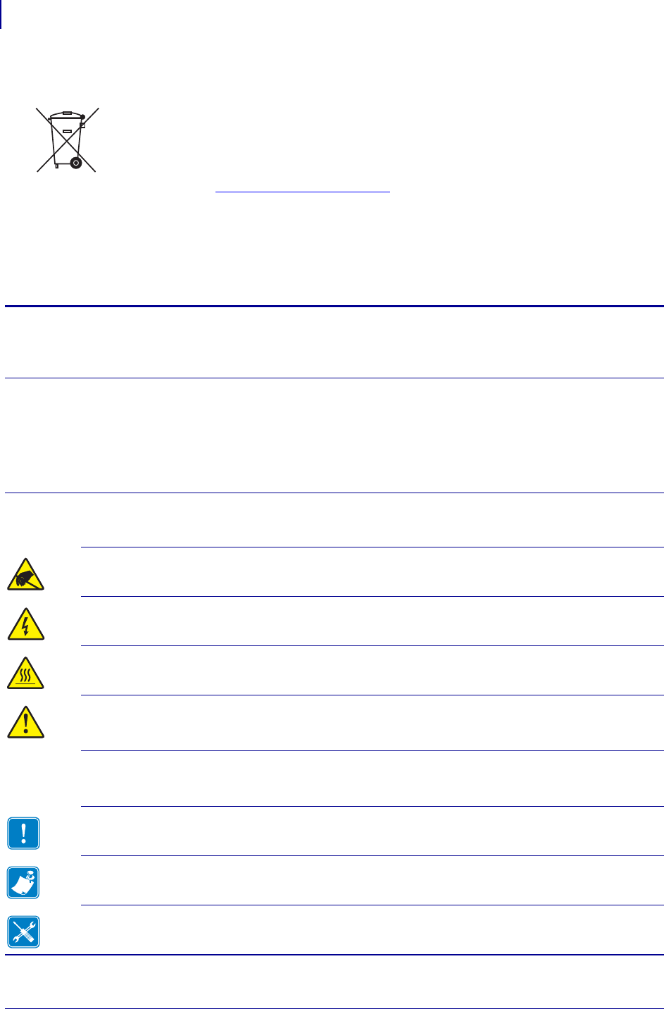
Do not dispose of this product in unsorted municipal waste. This product is recyclable, and
should be recycled according to your local standards.
For more information, please see our website at:
Web address: www.zebra.com/environment
Table 1 • Document Conventions
Alternate Color
If you are viewing this guide on-line, you can click the blue text used for cross-references or
hyper-links to jump directly to other sections in the guide or to web sites on the Internet.
Command Line Examples, File Names, and Directories
Command line examples, file names, and directories appear in a Typewriter style
(Courier) mono-spaced font. For example:
Type ZTools to get to the Post-Install scripts in the /bin directory.
Open the Zebra<version number>.tar file in the /root directory.
Icons and Advisory Words
The following icons and advisory words are used to draw your attention to certain areas of text.
Caution • Warns you of the potential for electrostatic discharge.
Caution • Warns you of a potential electric shock situation.
Caution • Warns you of a situation where excessive heat could cause a burn.
Caution • Advises you that failure to take or avoid a specific action could result in physical
harm to you.
(No icon) Caution • Advises you that failure to take or avoid a specific action could result in physical
harm to the hardware.
Important • Advises you of information that is essential to complete a task.
Note • Indicates neutral or positive information that emphasizes or supplements important
points of the main text.
Tools • Tells you what tools you need to complete a given task.

1/16/2014 ZD500 Series™ User’s Guide P1062653-002 Rev. A
Contents
Compliance and Regulatory Statements. . . . . . . . . . . . . . . . . . . . . . . . . . . . . . . . . . . . . . . iii
Environmental Management . . . . . . . . . . . . . . . . . . . . . . . . . . . . . . . . . . . . . . . . . . . . . . . viii
Document Conventions. . . . . . . . . . . . . . . . . . . . . . . . . . . . . . . . . . . . . . . . . . . . . . . . . . . viii
• Contents . . . . . . . . . . . . . . . . . . . . . . . . . . . . . . . . . . . . . . . . . . . . . . . . . . . . . . . . ix
1 • Introduction . . . . . . . . . . . . . . . . . . . . . . . . . . . . . . . . . . . . . . . . . . . . . . . . . . . . 1
ZD500 Series™ Thermal Printers. . . . . . . . . . . . . . . . . . . . . . . . . . . . . . . . . . . . . . . . . . . . 1
The ZD500 Series™ printer features:. . . . . . . . . . . . . . . . . . . . . . . . . . . . . . . . . . . . . . 2
The ZD500 Series™ printer options: . . . . . . . . . . . . . . . . . . . . . . . . . . . . . . . . . . . . . . 2
What’s in the Box? . . . . . . . . . . . . . . . . . . . . . . . . . . . . . . . . . . . . . . . . . . . . . . . . . . . . . . . 4
Unpack and Inspect the Printer . . . . . . . . . . . . . . . . . . . . . . . . . . . . . . . . . . . . . . . . . . 4
Printer Features . . . . . . . . . . . . . . . . . . . . . . . . . . . . . . . . . . . . . . . . . . . . . . . . . . . . . . . . . 5
Control Panel . . . . . . . . . . . . . . . . . . . . . . . . . . . . . . . . . . . . . . . . . . . . . . . . . . . . . . . . . . . 8
Control Panel Display Menu and Status Icons . . . . . . . . . . . . . . . . . . . . . . . . . . . . . . . . . 10
Printer Control Panel Display . . . . . . . . . . . . . . . . . . . . . . . . . . . . . . . . . . . . . . . . . . . . . . .11
Navigating through Screens in the Menu . . . . . . . . . . . . . . . . . . . . . . . . . . . . . . . . . . 12
Control Panel Menu Map . . . . . . . . . . . . . . . . . . . . . . . . . . . . . . . . . . . . . . . . . . . . . . . . . 14
2 • Setup . . . . . . . . . . . . . . . . . . . . . . . . . . . . . . . . . . . . . . . . . . . . . . . . . . . . . . . . . 15
Select a Location for the Printer . . . . . . . . . . . . . . . . . . . . . . . . . . . . . . . . . . . . . . . . . . . . 16
Attaching Power . . . . . . . . . . . . . . . . . . . . . . . . . . . . . . . . . . . . . . . . . . . . . . . . . . . . . . . . 17
Preparing and Handling Media . . . . . . . . . . . . . . . . . . . . . . . . . . . . . . . . . . . . . . . . . . . . . 18
Media Storage Tips . . . . . . . . . . . . . . . . . . . . . . . . . . . . . . . . . . . . . . . . . . . . . . . . . . . 18
Setting the Printer Menu and Report Display Language. . . . . . . . . . . . . . . . . . . . . . . . . . 19
Loading Roll Media . . . . . . . . . . . . . . . . . . . . . . . . . . . . . . . . . . . . . . . . . . . . . . . . . . . . . . 20
Loading Transfer Ribbon. . . . . . . . . . . . . . . . . . . . . . . . . . . . . . . . . . . . . . . . . . . . . . . . . . 23
Test Printing with Configuration Report Printouts . . . . . . . . . . . . . . . . . . . . . . . . . . . . . . . 27

Contents
x
P1062653-002 Rev. A ZD500 Series™ User’s Guide 1/16/2014
Connecting your Printer to a Computer . . . . . . . . . . . . . . . . . . . . . . . . . . . . . . . . . . . . . . 28
Interface Cable Requirements . . . . . . . . . . . . . . . . . . . . . . . . . . . . . . . . . . . . . . . . . . 28
USB Interface . . . . . . . . . . . . . . . . . . . . . . . . . . . . . . . . . . . . . . . . . . . . . . . . . . . . . . 29
Serial Interface . . . . . . . . . . . . . . . . . . . . . . . . . . . . . . . . . . . . . . . . . . . . . . . . . . . . . . 30
Wired (Ethernet) Interface . . . . . . . . . . . . . . . . . . . . . . . . . . . . . . . . . . . . . . . . . . . . . 31
ZebraNet® Internal Wireless Print Server Option . . . . . . . . . . . . . . . . . . . . . . . . . . . . . . . 33
Configure Using the Connectivity Wizard . . . . . . . . . . . . . . . . . . . . . . . . . . . . . . . . . . . . . 34
Bluetooth Option Configuration. . . . . . . . . . . . . . . . . . . . . . . . . . . . . . . . . . . . . . . . . . . . . 43
Connecting to a Windows Vista® SP2 or Windows 7® Master Device . . . . . . . . . . . 45
After Your Printer is Connected. . . . . . . . . . . . . . . . . . . . . . . . . . . . . . . . . . . . . . . . . . . . . 49
3 • Printer Configuration . . . . . . . . . . . . . . . . . . . . . . . . . . . . . . . . . . . . . . . . . . . 51
Changing Printer Settings . . . . . . . . . . . . . . . . . . . . . . . . . . . . . . . . . . . . . . . . . . . . . . . . . 51
SETTINGS Menu . . . . . . . . . . . . . . . . . . . . . . . . . . . . . . . . . . . . . . . . . . . . . . . . . . . . 52
TOOLS Menu . . . . . . . . . . . . . . . . . . . . . . . . . . . . . . . . . . . . . . . . . . . . . . . . . . . . . . . 56
NETWORK Menu . . . . . . . . . . . . . . . . . . . . . . . . . . . . . . . . . . . . . . . . . . . . . . . . . . . . 61
RFID Menu . . . . . . . . . . . . . . . . . . . . . . . . . . . . . . . . . . . . . . . . . . . . . . . . . . . . . . . . . 65
LANGUAGE Menu . . . . . . . . . . . . . . . . . . . . . . . . . . . . . . . . . . . . . . . . . . . . . . . . . . . 69
SENSOR Menu. . . . . . . . . . . . . . . . . . . . . . . . . . . . . . . . . . . . . . . . . . . . . . . . . . . . . . 71
PORTS Menu . . . . . . . . . . . . . . . . . . . . . . . . . . . . . . . . . . . . . . . . . . . . . . . . . . . . . . . 72
BLUETOOTH Menu . . . . . . . . . . . . . . . . . . . . . . . . . . . . . . . . . . . . . . . . . . . . . . . . . . 74
Manual Calibration - Media . . . . . . . . . . . . . . . . . . . . . . . . . . . . . . . . . . . . . . . . . . . . . . . . 75
RFID Calibration . . . . . . . . . . . . . . . . . . . . . . . . . . . . . . . . . . . . . . . . . . . . . . . . . . . . . . . . 76
4 • Print Operations . . . . . . . . . . . . . . . . . . . . . . . . . . . . . . . . . . . . . . . . . . . . . . . 77
Determining Printer Configuration. . . . . . . . . . . . . . . . . . . . . . . . . . . . . . . . . . . . . . . . . . . 78
Thermal Printing . . . . . . . . . . . . . . . . . . . . . . . . . . . . . . . . . . . . . . . . . . . . . . . . . . . . . 78
Modes of Printing . . . . . . . . . . . . . . . . . . . . . . . . . . . . . . . . . . . . . . . . . . . . . . . . . . . . 78
Setting the Thermal Print Method . . . . . . . . . . . . . . . . . . . . . . . . . . . . . . . . . . . . . . . . 79
Types of Media . . . . . . . . . . . . . . . . . . . . . . . . . . . . . . . . . . . . . . . . . . . . . . . . . . . . . . . . . 79
Determining Thermal Media Types. . . . . . . . . . . . . . . . . . . . . . . . . . . . . . . . . . . . . . . 79
Media Loading . . . . . . . . . . . . . . . . . . . . . . . . . . . . . . . . . . . . . . . . . . . . . . . . . . . . . . . . . 81
Attaching the 3 inch Core Adapters . . . . . . . . . . . . . . . . . . . . . . . . . . . . . . . . . . . . . . 81
Loading 3 inch I.D. Media rolls . . . . . . . . . . . . . . . . . . . . . . . . . . . . . . . . . . . . . . . . . . 82
Removing the 3 inch Core Adapters. . . . . . . . . . . . . . . . . . . . . . . . . . . . . . . . . . . . . . 83
Ribbon Overview. . . . . . . . . . . . . . . . . . . . . . . . . . . . . . . . . . . . . . . . . . . . . . . . . . . . . . . . 84
When to Use Ribbon. . . . . . . . . . . . . . . . . . . . . . . . . . . . . . . . . . . . . . . . . . . . . . . . . . 84
Coated Side of Ribbon . . . . . . . . . . . . . . . . . . . . . . . . . . . . . . . . . . . . . . . . . . . . . . . . 84
Ribbon Test with Adhesive . . . . . . . . . . . . . . . . . . . . . . . . . . . . . . . . . . . . . . . . . . . . . 84
Ribbon Scratch Test . . . . . . . . . . . . . . . . . . . . . . . . . . . . . . . . . . . . . . . . . . . . . . . . . . 85
Replacing Supplies . . . . . . . . . . . . . . . . . . . . . . . . . . . . . . . . . . . . . . . . . . . . . . . . . . . . . . 86
Adding a New Transfer Ribbon. . . . . . . . . . . . . . . . . . . . . . . . . . . . . . . . . . . . . . . . . . 86
Replacing a Partially Used Transfer Ribbon . . . . . . . . . . . . . . . . . . . . . . . . . . . . . . . . 86

xi
Contents
1/16/2014 ZD500 Series™ User’s Guide P1062653-002Rev. A
Adjusting the Print Width. . . . . . . . . . . . . . . . . . . . . . . . . . . . . . . . . . . . . . . . . . . . . . . . . . 87
Adjusting the Print Quality. . . . . . . . . . . . . . . . . . . . . . . . . . . . . . . . . . . . . . . . . . . . . . . . . 87
Media Sensing . . . . . . . . . . . . . . . . . . . . . . . . . . . . . . . . . . . . . . . . . . . . . . . . . . . . . . . . . 88
Using the Movable Black Mark Sensor . . . . . . . . . . . . . . . . . . . . . . . . . . . . . . . . . . . . . . . 89
Adjusting the Movable Sensor for Black Marks or Notches . . . . . . . . . . . . . . . . . . . . 90
Adjusting the Movable Sensor for Web (Gap) Sensing . . . . . . . . . . . . . . . . . . . . . . . 92
Printing on Fan-Fold Media. . . . . . . . . . . . . . . . . . . . . . . . . . . . . . . . . . . . . . . . . . . . . . . . 93
Printing with Externally Mounted Roll Media. . . . . . . . . . . . . . . . . . . . . . . . . . . . . . . . . . . 95
Sending Files to the Printer. . . . . . . . . . . . . . . . . . . . . . . . . . . . . . . . . . . . . . . . . . . . . . . . 95
Fonts and Your Printer . . . . . . . . . . . . . . . . . . . . . . . . . . . . . . . . . . . . . . . . . . . . . . . . . . . 96
Identifying Fonts in Your Printer . . . . . . . . . . . . . . . . . . . . . . . . . . . . . . . . . . . . . . . . . 96
Localizing the Printer with Code Pages . . . . . . . . . . . . . . . . . . . . . . . . . . . . . . . . . . . 96
Asian fonts and Other Large Font Sets. . . . . . . . . . . . . . . . . . . . . . . . . . . . . . . . . . . . 97
Getting Asian Fonts . . . . . . . . . . . . . . . . . . . . . . . . . . . . . . . . . . . . . . . . . . . . . . . . . . 97
5 • Printer Options . . . . . . . . . . . . . . . . . . . . . . . . . . . . . . . . . . . . . . . . . . . . . . . . 99
Label Dispenser Option . . . . . . . . . . . . . . . . . . . . . . . . . . . . . . . . . . . . . . . . . . . . . . . . . 100
Cutter Option. . . . . . . . . . . . . . . . . . . . . . . . . . . . . . . . . . . . . . . . . . . . . . . . . . . . . . . . . . 103
Loading Media with the Cutter Option . . . . . . . . . . . . . . . . . . . . . . . . . . . . . . . . . . . 104
ZebraNet® Internal Wireless Print Server Option . . . . . . . . . . . . . . . . . . . . . . . . . . . . . . 106
Bluetooth Option . . . . . . . . . . . . . . . . . . . . . . . . . . . . . . . . . . . . . . . . . . . . . . . . . . . . . . . 107
Printer Network Configuration Status Label . . . . . . . . . . . . . . . . . . . . . . . . . . . . . . . 108
6 • Maintenance . . . . . . . . . . . . . . . . . . . . . . . . . . . . . . . . . . . . . . . . . . . . . . . . . . 109
Cleaning . . . . . . . . . . . . . . . . . . . . . . . . . . . . . . . . . . . . . . . . . . . . . . . . . . . . . . . . . . . . . .110
Cleaning the Printhead . . . . . . . . . . . . . . . . . . . . . . . . . . . . . . . . . . . . . . . . . . . . . . . .111
Media Path Cleaning . . . . . . . . . . . . . . . . . . . . . . . . . . . . . . . . . . . . . . . . . . . . . . . . .112
Sensor Cleaning . . . . . . . . . . . . . . . . . . . . . . . . . . . . . . . . . . . . . . . . . . . . . . . . . . . . .113
Platen Cleaning and Replacement . . . . . . . . . . . . . . . . . . . . . . . . . . . . . . . . . . . . . . .114
Other Printer Maintenance . . . . . . . . . . . . . . . . . . . . . . . . . . . . . . . . . . . . . . . . . . . . .116
RTC Battery . . . . . . . . . . . . . . . . . . . . . . . . . . . . . . . . . . . . . . . . . . . . . . . . . . . . . . . . . . .116
Fuses . . . . . . . . . . . . . . . . . . . . . . . . . . . . . . . . . . . . . . . . . . . . . . . . . . . . . . . . . . . . . . . .116
Replacing the Printhead . . . . . . . . . . . . . . . . . . . . . . . . . . . . . . . . . . . . . . . . . . . . . . . . . .117
7 • Troubleshooting . . . . . . . . . . . . . . . . . . . . . . . . . . . . . . . . . . . . . . . . . . . . . . 123
Error Messages. . . . . . . . . . . . . . . . . . . . . . . . . . . . . . . . . . . . . . . . . . . . . . . . . . . . . . . . 124
Printing Issues . . . . . . . . . . . . . . . . . . . . . . . . . . . . . . . . . . . . . . . . . . . . . . . . . . . . . . . . 126
Ribbon Problems . . . . . . . . . . . . . . . . . . . . . . . . . . . . . . . . . . . . . . . . . . . . . . . . . . . . . . 129
Communications Problems . . . . . . . . . . . . . . . . . . . . . . . . . . . . . . . . . . . . . . . . . . . . . . . 130
Miscellaneous Issues . . . . . . . . . . . . . . . . . . . . . . . . . . . . . . . . . . . . . . . . . . . . . . . . . . . 131
RFID Troubleshooting. . . . . . . . . . . . . . . . . . . . . . . . . . . . . . . . . . . . . . . . . . . . . . . . . . . 132

Contents
xii
P1062653-002 Rev. A ZD500 Series™ User’s Guide 1/16/2014
Printer Diagnostics . . . . . . . . . . . . . . . . . . . . . . . . . . . . . . . . . . . . . . . . . . . . . . . . . . . . . 133
Power-On Self Test. . . . . . . . . . . . . . . . . . . . . . . . . . . . . . . . . . . . . . . . . . . . . . . . . . 133
Configuration Report. . . . . . . . . . . . . . . . . . . . . . . . . . . . . . . . . . . . . . . . . . . . . . . . . 134
Print Quality Report . . . . . . . . . . . . . . . . . . . . . . . . . . . . . . . . . . . . . . . . . . . . . . . . . 135
Reset Printer Factory Defaults . . . . . . . . . . . . . . . . . . . . . . . . . . . . . . . . . . . . . . . . . 138
Reset Network Factory Defaults . . . . . . . . . . . . . . . . . . . . . . . . . . . . . . . . . . . . . . . . 138
Communication Diagnostics Test . . . . . . . . . . . . . . . . . . . . . . . . . . . . . . . . . . . . . . . 139
Sensor Profile . . . . . . . . . . . . . . . . . . . . . . . . . . . . . . . . . . . . . . . . . . . . . . . . . . . . . . 140
A • Appendix: Interface Wiring . . . . . . . . . . . . . . . . . . . . . . . . . . . . . . . . . . . . . 143
Serial Port Interface . . . . . . . . . . . . . . . . . . . . . . . . . . . . . . . . . . . . . . . . . . . . . . . . . . . . 144
Connecting the Printer to a DTE Device . . . . . . . . . . . . . . . . . . . . . . . . . . . . . . . . . 144
B • Appendix: Dimensions . . . . . . . . . . . . . . . . . . . . . . . . . . . . . . . . . . . . . . . . . 145
External ZD500 Series™ Printer Dimensions. . . . . . . . . . . . . . . . . . . . . . . . . . . . . . . . . 146
Label Dispenser . . . . . . . . . . . . . . . . . . . . . . . . . . . . . . . . . . . . . . . . . . . . . . . . . . . . 147
Cutter . . . . . . . . . . . . . . . . . . . . . . . . . . . . . . . . . . . . . . . . . . . . . . . . . . . . . . . . . . . . 147

1/16/2014 ZD500 Series™ Thermal Transfer Printer User’s Guide P1062653-002 Rev. A
1
Introduction
This section introduces you to your new Zebra® ZD500 Series™ desktop thermal label
printer. It describes what you get in your shipping box and provides an overview of printer
features. It also includes procedures that describe how to open and close the printer and
report any problems.
Your printer, when connected to a host computer, functions as a complete system for
printing labels, receipts, forms, and tags.
This users guide provides all the information you need to operate your printer on a daily
basis.
ZD500 Series™ Thermal Printers
The Zebra® ZD500 Series™ models are desktop thermal label printers with the widest
range of features and options including an internal UHF RFID encoder option.
• The 203 dpi (dots per inch print density) version printer provides thermal transfer and
direct thermal printing at speeds up to 6 ips (inches per second).
• The 300 dpi version printer provides thermal transfer and direct thermal printing at
speeds up to 4 ips.
• These printers support ZPL™ Zebra printer programming language and a wide variety
of interface and feature options.

Introduction
ZD500 Series™ Thermal Printers
2
P1062653-002 Rev. A ZD500 Series™ Thermal Transfer Printer User’s Guide 1/16/2014
The ZD500 Series™ printer features:
• A user display and control panel for easier installation and direct access feature
controls typically found only in premium printers.
• OpenAccess™ design for simplified media loading.
• Color-coded operator controls and media guides.
• Zebra™ Global Printing Solution – supports Microsoft Windows keyboard encoding
(and ANSI), Unicode UTF-8 and UTF 16 (Unicode Transformation Formats), XML,
ASCII (7 and 8 bit used by legacy programs and systems), basic single and double
byte font encoding, JIS and Shift-JIS (Japanese International Standards), Hexadecimal
encoding, and custom character mapping (DAT table creation, font linking, and
character remapping).
• On–The –Fly OpenType and TrueType font scaling and import, Unicode, resident
scalable font, and a selection of resident bitmap fonts.
• XML-Enabled printing—allows XML communications for bar code label printing,
eliminating license fees and print server hardware and lowering customization and
programming costs.
• Movable Sensor: A full width movable black mark or notch sensor, and multi center
position transmissive (label gap/web) sensor.
• 56 MB of user accessible flash memory for storing forms, fonts, and graphics.
• USB 2.0, Serial RS-232 and bi-directional parallel ports.
• Internal ZebraNet10/100 Print Server—supports 10Base-T, 100Base-TX and fast
Ethernet 10/100 auto-switching networks.
• On-board RTC (Real Time Clock).
• Printhead maintenance reporting enabled and customizable by the user.
The ZD500 Series™ printer options:
• Internal UHF RFID Encoder (See the RFID Programmimg Guide 3 for details)
• Label Dispense (Peel-Off Liner and Present Label for Operator).
• General purpose media cutter.
• Wi-Fi (802.11a/b/g/n)
• Bluetooth 3.0
• Pre-loaded Swiss 721 Latin 1 font (for EU zone printers). Font is available for
download.
• Asian Language support with printer configuration options for the large Simplified
and Traditional Chinese, Japanese, or Korean character sets. Printers sold in China
have the Simplified Chinese SimSun font pre-installed.
• Zebra® ZBI 2.0™ (Zebra BASIC Interpreter) programming language. ZBI allows you
to create custom printer operations that can automate processes, use peripherals (i.e.
scanners, scales, keyboards, Zebra® ZKDU™, etc.) all without being attached to a PC
or network.

3
Introduction
ZD500 Series™ Thermal Printers
1/16/2014 ZD500 Series™ Thermal Transfer Printer User’s Guide P1062653-002 Rev. A
Your printer, when connected to a host computer, functions as a complete system for
printing labels, receipts, forms, and tags. Many printer settings may also be controlled by
your printer’s driver or label design software. Refer to the driver or software
documentation for more information.
To create label formats, refer to your programming guides or label design applications
such as the free label and form design software: ZebraDesigner™.
The printer includes a complete suite of free Link-OS software applications and drivers to
configure printer settings, design and print labels and receipts, get printer status, import
graphics and fonts, send programming commands, update firmware, and download files.
Clone printer settings and send graphics, files, fonts, and firmware (updates) to one or
more Zebra® Ethernet and locally connected printers with ZebraNet™ Bridge.
Introduction
What’s in the Box?
4
P1062653-002 Rev. A ZD500 Series™ Thermal Transfer Printer User’s Guide 1/16/2014
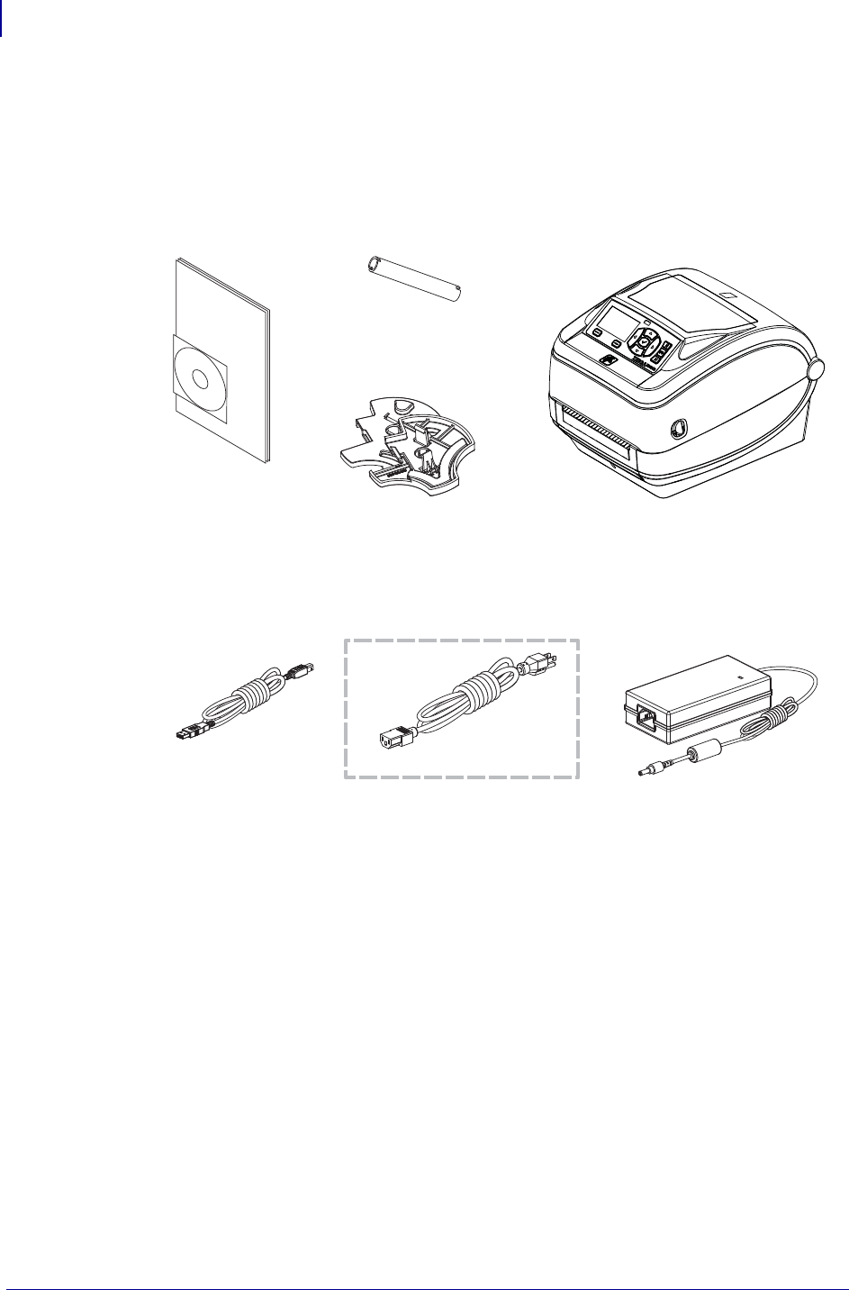
What’s in the Box?
Save the carton and all packing materials in case you need to ship or store the printer later.
After unpacking, make sure you have all parts. Follow the procedures for inspecting the
printer to familiarize yourself with printer parts so you can follow the instructions in this
book.
Unpack and Inspect the Printer
When you receive the printer, immediately unpack it and inspect for shipping damage.
• Save all packing materials.
• Check all exterior surfaces for damage.
• Open the printer and inspect the media compartment for damage to components.
If you discover shipping damage upon inspection:
• Immediately notify the shipping company and file a damage report. Zebra
Technologies Corporation is not responsible for any damage to the printer
incurred during shipment, and will not cover the repair of this damage under its
warranty policy.
• Keep all packaging material for shipping company inspection.
• Notify your authorized Zebra® reseller.
Power Cord
varies by locale or region
Documentation
and Software
Power
Supply
USB Cable
Printer
Ribbon Core
3in (76.2 mm) I.D.
Media Roll Adapters
5
Introduction
Printer Features
1/16/2014 ZD500 Series™ Thermal Transfer Printer User’s Guide P1062653-002 Rev. A
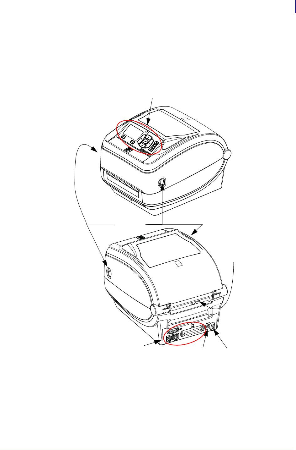
Printer Features
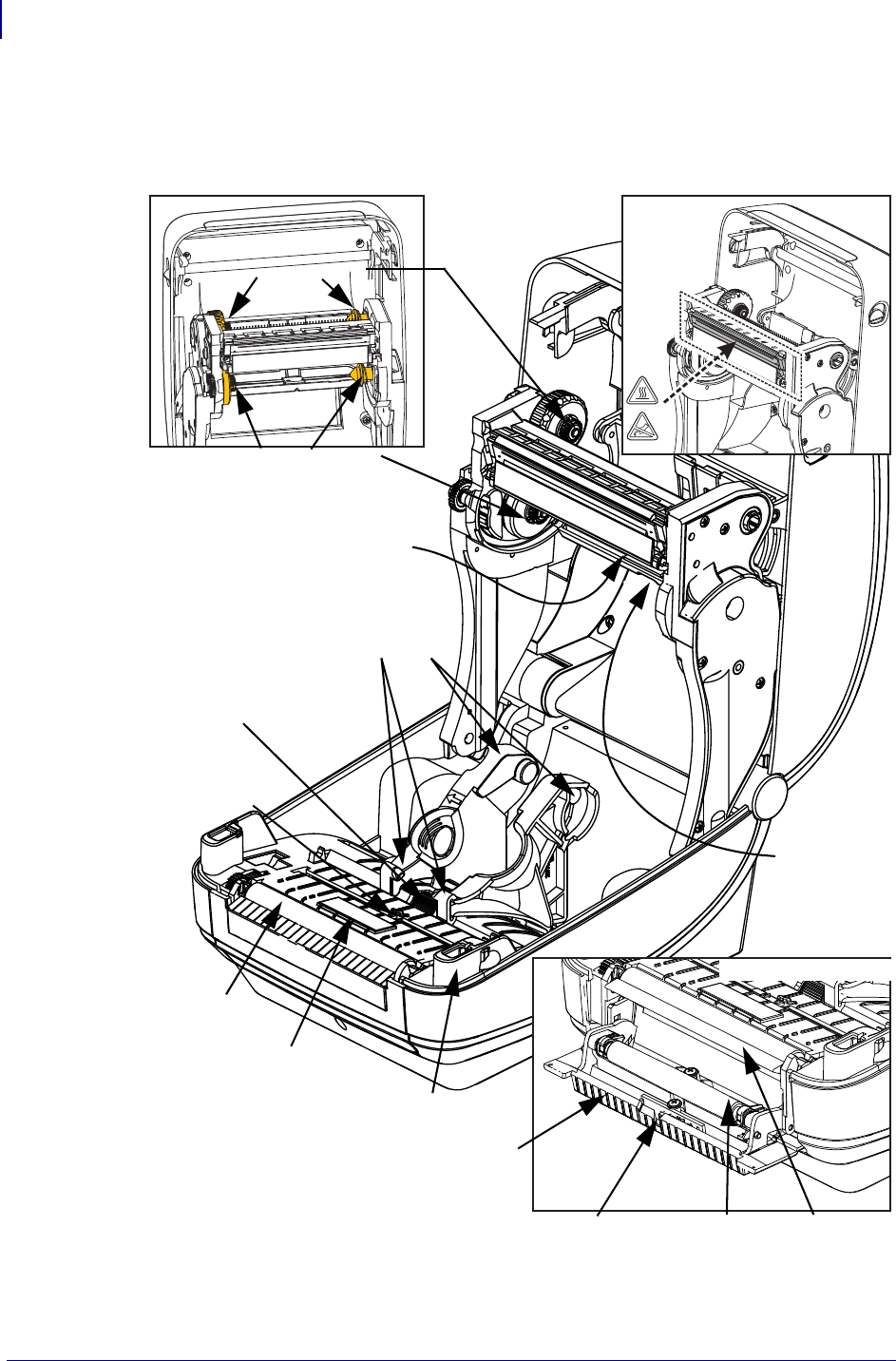
Figure 1 shows features on the outside and Figure 2 shows features inside the media
compartment of your printer. Depending on the printer model and the installed options,
your printer may look slightly different.
Figure 1 • Printer Features
Interface
Connectors
Control Panel
Release
Latches
Release
Latches
DC Power
Receptacle
Power
Switch
Fan-Fold Media
Entry Slot
Introduction
Printer Features
6
P1062653-002 Rev. A ZD500 Series™ Thermal Transfer Printer User’s Guide 1/16/2014
Figure 2 • Printer Features Continued
Label Taken
Sensor
Peel Bar
Platen
Roller
Printhead
Movable
Black Mark
Sensor
Ribbon Trailer Sensor
(hidden from view)
Roll Holders and
Media Guides
Head-Up Sensor
(inside)
Pinch
Roller
Dispenser Door
(open)
Take Up Spindles
Supply Spindles
Ribbon Roll Holders
Dispenser Option
Web (Gap)
Sensor
Media Guide Stop
Adjustment
RFID Antenna
(inside)
7
Introduction
Printer Features
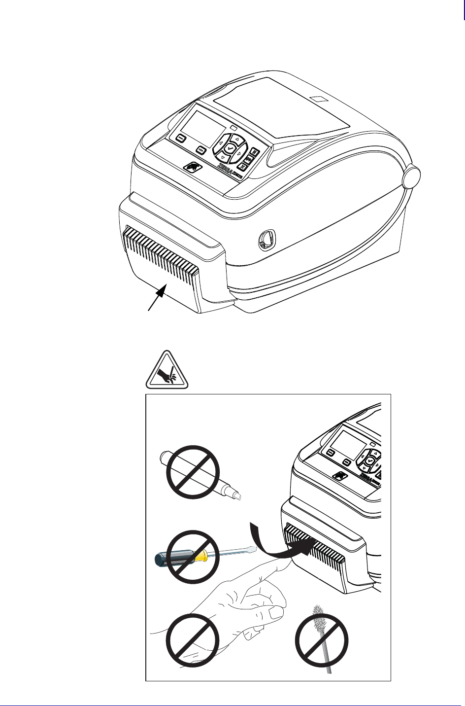
1/16/2014 ZD500 Series™ Thermal Transfer Printer User’s Guide P1062653-002 Rev. A
Figure 3 • Printer Features - Cutter Option
Media Cutter
(Option)
Introduction
Control Panel
8
P1062653-002 Rev. A ZD500 Series™ Thermal Transfer Printer User’s Guide 1/16/2014
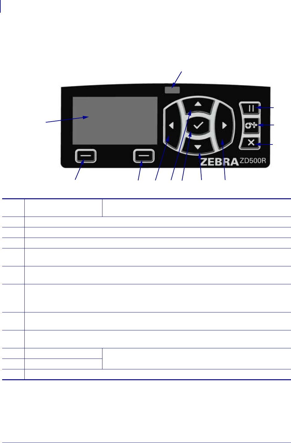
Control Panel
The control panel indicates the printer’s operating status and allows the user to control
basic printer operation.
Add
12
6 5811 9 7
1
2
3
4
Figure 4 • ZD500 Series™ Control Panel
10
1STATUS light Shows the current status of the printer. For more information, see
Table 1 on page 9.
2The PAUSE button starts or stops printer operation when pressed.
3The FEED button forces the printer to feed one blank label each time the button is pressed.
4The CANCEL button cancels print jobs when the printer is paused.
5The RIGHT ARROW button, which is active only in the menu system, navigates to the right
through the main menu and to previous items in sub-menus.
6The DOWN ARROW button changes the parameter values. Common uses are to decrease a value
or to scroll through choices.
7The SELECT () button operates as follows:
•When on the Home screen, pressing enters the menu system.
•When in the menu system, pressing accepts the values shown.
8The UP ARROW button changes the parameter values. Common uses are to increase a value or to
scroll through choices.
9The LEFT ARROW button, which is active only in the menu system, navigates to the left through
the main menu and to the next item in sub-menus.
10 RIGHT OPTION button These buttons execute the actions or commands shown directly above
them in the display.
11 LEFT OPTION button
12 The display shows the printer’s operating status and allows the user to navigate the menu system.
9
Introduction
Control Panel
1/16/2014 ZD500 Series™ Thermal Transfer Printer User’s Guide P1062653-002 Rev. A
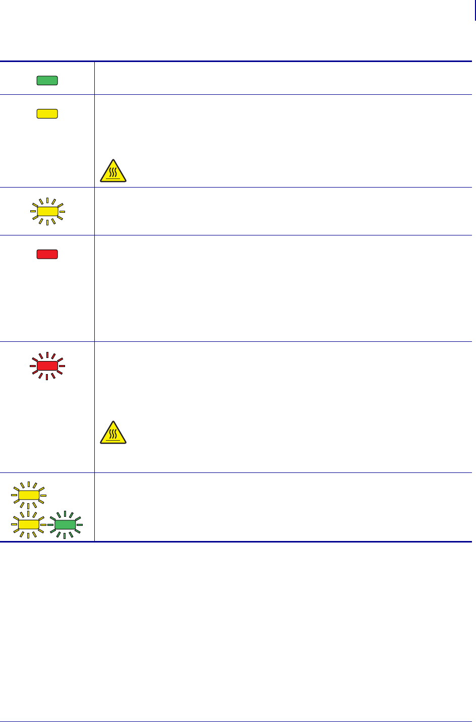
Table 1 • Printer Status Indicator Light
STATUS light steady green
The printer is ready.
STATUS light steady amber
This indicator light on steady indicates one of the following:
•The printer is not ready.
•The printhead is over temperature.
Caution • The printhead may be hot and could cause severe burns. Allow
the printhead to cool.
STATUS light flashing amber
This indicator light flashing indicates one of the following:
•The printhead is under temperature.
STATUS light steady red
This indicator light on steady indicates one of the following:
•The media supply is out.
•The ribbon supply is out.
•The printhead is open.
•Cutter malfunction.
The printer needs attention and cannot continue without user intervention.
STATUS light flashing red
This indicator light flashing indicates one of the following:
•The printer is unable to correctly identify the printhead type.
•The main logic board (MLB) is over temperature.
•The printhead is extremely over temperature.
Caution • The printhead may be hot and could cause severe burns. Allow
the printhead to cool.
The printer needs attention and cannot continue without user intervention.
STATUS light flashing amber followed by alternating amber/ green
This status light condition indicates the printer is in Forced Download Mode.
Forced Download Mode is used to download new firmware to the printer. This
mode should only be used by trained personnel.
Introduction
Control Panel Display Menu and Status Icons
10
P1062653-002 Rev. A ZD500 Series™ Thermal Transfer Printer User’s Guide 1/16/2014
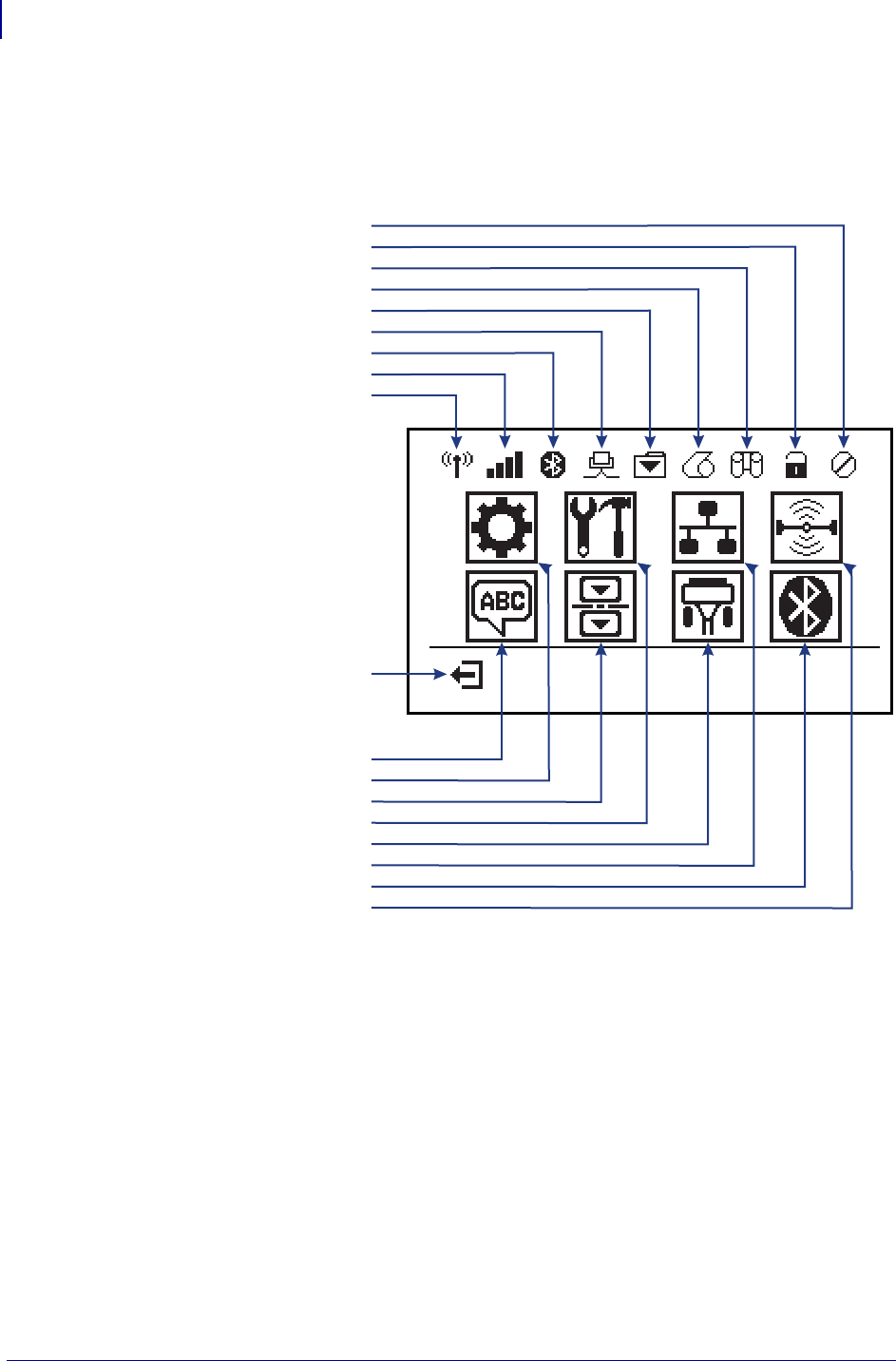
Control Panel Display Menu and Status Icons
Figure 5 • Typical Home Menu
Error
Cover Unlocked
Ribbon In
Media In
Data
Ethernet
Bluetooth
Signal Strength
WiFi
Previous Menu Shortcut
Language Menu
Settings Menu
Sensors Menu
Tools Menu
Ports Menu
Network Menu
Bluetooth Menu
RFID Menu
11
Introduction
Printer Control Panel Display
1/16/2014 ZD500 Series™ Thermal Transfer Printer User’s Guide P1062653-002 Rev. A
Printer Control Panel Display
The printer’s control panel includes a display, where you can view the printer’s status or
change its operating parameters. In this section, you will learn how to navigate through the
printer’s menu system and change values for menu items.
After the printer completes the power-up sequence, it moves to the Idle Display (Figure 6).
If a print server is installed, the printer cycles through the information shown and the
printer’s IP address.
Figure 6 • Idle Display
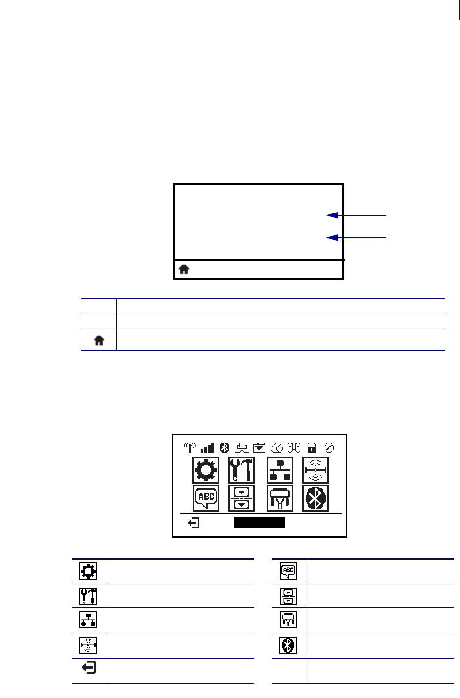
The printer’s operating parameters are organized into several user menus, which you can
access through the printer’s Home menu (Figure 7). For detailed information about
changing the printer settings, see Printer Configuration on page 51.
Figure 7 • Home Menu
1The printer’s current status
2Information that you set through TOOLS Menu on page 56 - IDLE DISPLAY
Home menu shortcut
See SETTINGS Menu on page 52.See LANGUAGE Menu
on page 69.
See TOOLS Menu on page 56.See SENSOR Menu on page 71.
See NETWORK Menu
on page 61.
See PORTS Menu on page 72.
See RFID Menu on page 65 See BLUETOOTH Menu
on page 74
Exit and return to the Idle Display
(Figure 6).
PRINTER READY
V74.19.1Z
1
2
SETTINGS
Introduction
Printer Control Panel Display
12
P1062653-002 Rev. A ZD500 Series™ Thermal Transfer Printer User’s Guide 1/16/2014
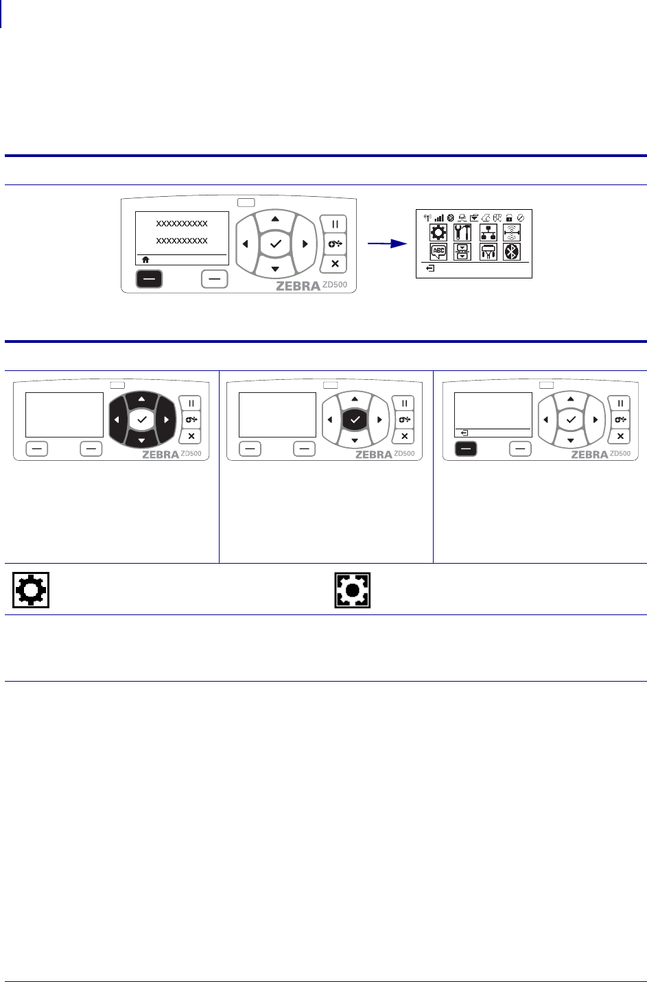
Navigating through Screens in the Menu
Table 2 shows navigating through the screens in the control panel display.
Table 2 • Navigation
Idle Display
At the Idle Display (Figure 6 on page 11), press LEFT SELECT to go
to the printer’s Home menu (Figure 7 on page 11).
Home Menu
To move from icon to icon in the
Home menu, press the ARROW
buttons.
When an icon is selected, its
image reverses to highlight it.
To select the highlighted menu
icon and enter the menu, press
SELECT () button.
Press LEFT SELECT to exit the
Home menu and return to the Idle
Display.
Note • The printer automatically returns to the Idle Display after 15 seconds of inactivity in the Home menu.
SETTINGS menu icon
SETTINGS menu icon highlighted
and active for selection.
13
Introduction
Printer Control Panel Display
1/16/2014 ZD500 Series™ Thermal Transfer Printer User’s Guide P1062653-002 Rev. A
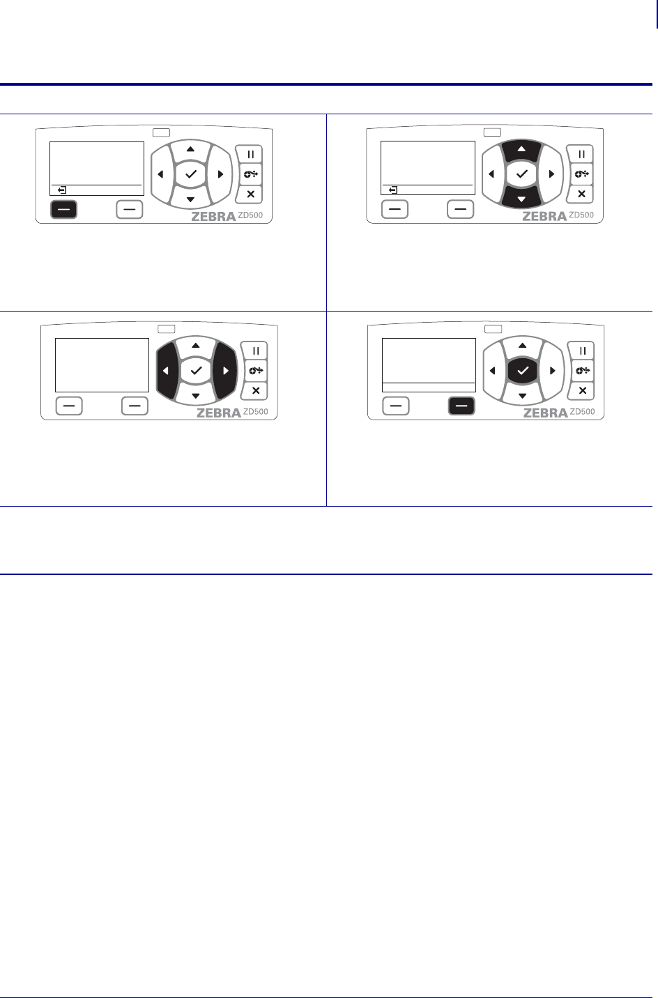
User Menus
Press LEFT SELECT to return to the Home menu. ▼and ▲ indicate that a value can be changed. Any
changes that you make are saved immediately.
Press the UP ARROW or DOWN ARROW to
scroll through accepted values.
To scroll through the items in a User menu, press the
LEFT ARROW or RIGHT ARROW.
A word in the bottom-right corner of the display
indicates an available action.
Press SELECT () button or press RIGHT
SELECT to perform the action shown.
Note • The printer automatically returns to the Home menu after 15 seconds of inactivity in a User menu.
Table 2 • Navigation
XXXXXXX
XXX
Introduction
Control Panel Menu Map
14
P1062653-002 Rev. A ZD500 Series™ Thermal Transfer Printer User’s Guide 1/16/2014
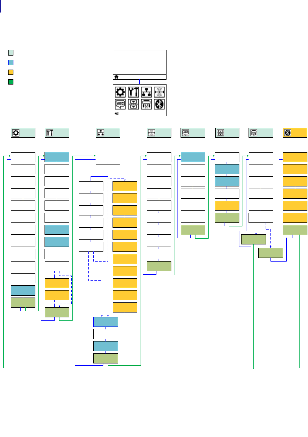
Control Panel Menu Map
Printer Ready
V74.xx.xxZ
Darkness
Print Speed
Media Type
Print Width
Print Mode
Tear Off
Reprint Mode
Power Up
Action
Head Close
Action
Tools Menu
Left Position
Label Length
Max
Language
ZBI Enabled?
Run ZBI
Program
Stop ZBI
Program
Parity
Baud Rate
Data Bits
Host
Handshake
WLAN IP
Protocol
ESSID
WLAN MAC
Address
WLAN Port
WLAN
Gateway
WLAN Subnet
Mask
WLAN IP
Address
Print
Information
Sensors Menu
ZPL Mode
Command
Character
Control
Character
Delimiter Char
ZPL Override
LCD Backlight
LCD Contrast
Idle Display
Manual
Calibration
Take Label
Sensor Type
Network Menu
Settings
Menu
Print
Information
RFID Menu
Ports Menu
Language
RFID Void
Count
Manual
Calibration
RFID Test
RFID Program
Position
RFID Read
Power
RFID Write
Power
RFID Status
RFID Read
Data
RFID Valid
Count
Language
Menu
Settings Menu
Min Security
Mode
Discovery
Connected
BT Spec
Version
Mode
Bluetooth
Address
Diagnostic
Mode
Wired IP
Protocol
Wired MAC
Address
Wired Port
Wired
Gateway
Wired Subnet
Mask
Wired IP
Address
Channel
Signal
Parallel Mode
Primary
Network
Print Method
Load Defaults
Label Sensor
Print
Information
Active Print
Server
Reset Network
Load Defaults
Label Top
RFID Calibrate
WML Version
WLAN
Installed
No
WLAN
Home Menu Items
Menu Item also in other Menus
Yes No
Go to next Menu group
Printer Option. May not be present.
Language
(Menu) htooteulBstroPsrosneSDIFRkrowteNslooTsgnitteS
Bluetooth
Menu
IP Port
IP Alternate
Port

1/16/2014 ZD500 Series™ Thermal Transfer Printer User’s Guide P1062653-002 Rev. A
2
Setup
This section assists you in setting up and operating your printer for the first time.
Basic Printer Setup (Overview)
The setup process to can be broken down to two (2) phases: hardware setup and host system
(software/driver) setup.
• Place the printer in a safe location with access to power and where cable or the
wireless option communications can access your printer.
• Attach the printer to a grounded AC power source.
• Select and prepare media for your printer.
• Load the media.
• Load the transfer ribbon if you are using thermal transfer media.
• Turn the printer ON. Print a ‘Configuration Report’ to verify basic printer operation.
• Turn the printer OFF.
• Choose method to communicate to your printer - Local connection via USB, Serial, or
Parallel ports; Local network via Ethernet (LAN); or using the printer’s wireless
option that supports Wi-Fi (802.11 a/b/g/n WLAN) and Bluetooth 3.0.
• Attach the printer to the network or host system, and configure the printer as required
for communicating to the print system host/network.
For supported Windows Operating systems (most common) with a Local (cabled) connection:
• ‘Run’ the Zebra Setup Utilities for systems from the User’s CD.
• Click on ‘Install New Printer’ and run the install wizard. Select ‘Install Printer’ and
select the ZD500R from the list of ZDesigner printers.
• Select the port (USB, Serial or Parallel) that you connected to the PC.
• Turn the printer ON and configure printer communications for your interface type.
• Print a Windows driver ‘Test Print’ to verify operation with Windows.

Setup
Select a Location for the Printer
16
P1062653-002 Rev. A ZD500 Series™ Thermal Transfer Printer User’s Guide 1/16/2014
Select a Location for the Printer
The printer and media need a clean safe area with moderate temperatures to have optimal print
operations.
Select a location for the printer that meets these conditions:
•Surface: The surface where the printer will be located must be solid, level, and of
sufficient size and strength to hold the printer.
•Space: The area where the printer will be located must include enough space for
ventilation, opening the printer (media access and cleaning), and for accessing the printer
components and connectors. To allow for proper ventilation and cooling, leave open space
on all sides of the printer.
•Power: The printer should be within a short distance of an appropriate power outlet that is
easily accessible.
•Data communication interfaces: The printer must be within range of your WLAN or
Bluetooth radio (if applicable) or within an acceptable range for other connectors to reach
your data source (usually a computer).
Data cables should not be routed with or near power cords or conduits, fluorescent
lighting, transformers, microwave ovens, motors or other electrical noise and interference
sources. These interference sources may interfere with communications, host system
operation, and printer functionality.
•Operating conditions: Your printer is designed to function in a wide range of
environmental and electrical conditions, including a warehouse or factory floor. Table 4
shows the temperature and relative humidity requirements for the printer when it is
operating.
Caution • Do not place any padding or cushioning material under or around the base
of the printer because this restricts air flow and could cause the printer to overheat.
Table 3 • Operating Temperature and Humidity
Mode Temperature Relative Humidity
Thermal Transfer 41° to 104°F (5° to 40°C) 20 to 85% non-condensing
Direct Thermal 32° to 104°F (0° to 40°C)
Table 4 • Non-Operating and Storage Temperature and Humidity
Mode Temperature Relative Humidity
Both -40° to 140°F (-40° to 60°C) 5 to 85% non-condensing
17
Setup
Attaching Power
1/16/2014 ZD500 Series™ Thermal Transfer Printer User’s Guide P1062653-002 Rev. A
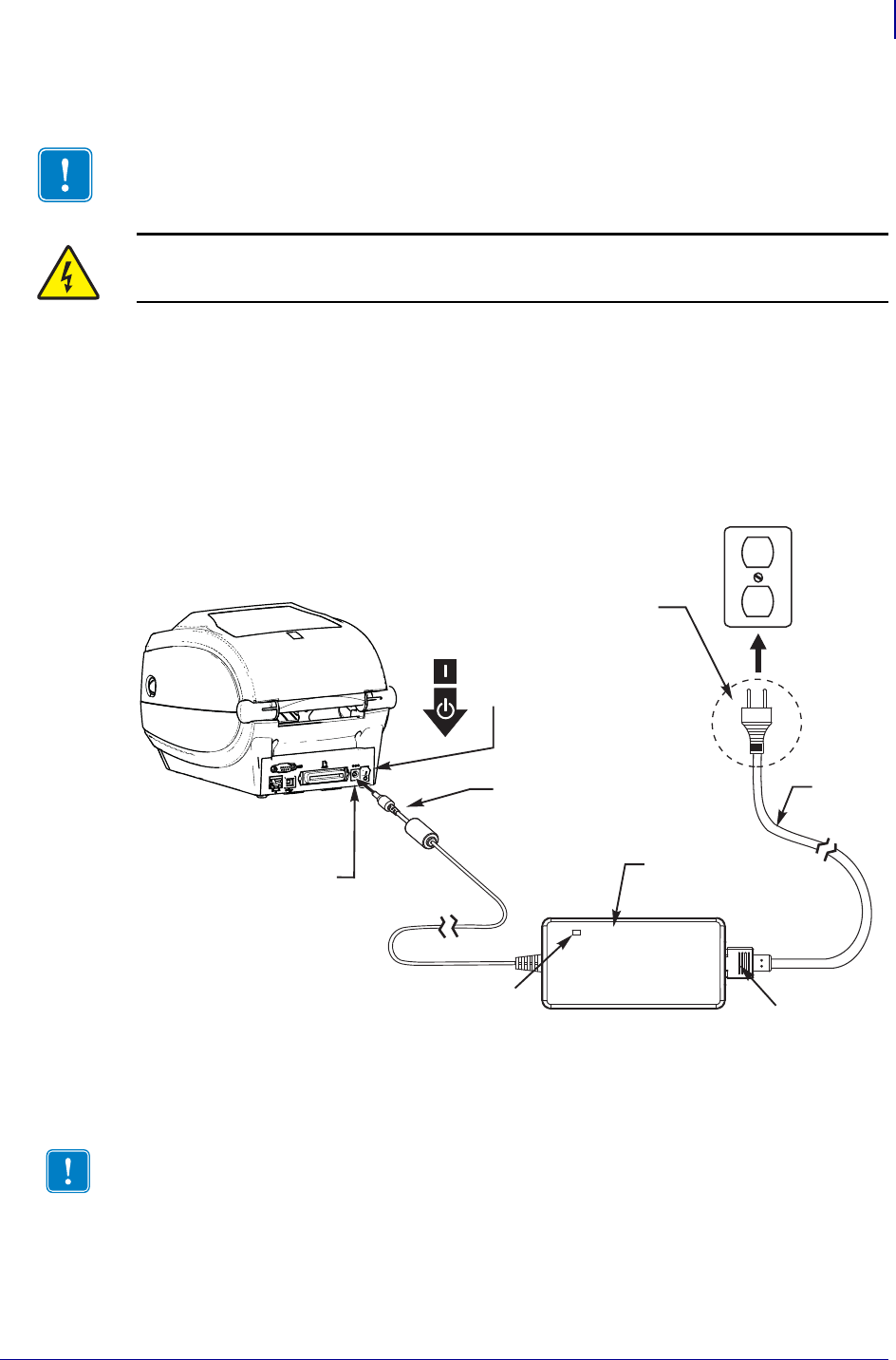
Attaching Power
1. Make sure the printer’s power switch is in the off position (down).
2. Insert the AC power cord into the power supply.
3. Plug the other end of the cord into an appropriate AC electrical outlet. Note: The active
power light will go on if power is on at the AC outlet.
4. Insert the power supply’s power connector into the printer’s power receptacle.
Important • Set up your printer so that you can handle the power cord easily if needed. To
make certain the printer cannot carry electrical current, you must separate the power cord
from the power supply receptacle or AC electrical outlet.
Caution • Never operate the printer and power supply in an area where they can get wet.
Serious personal injury could result!
Power
Connector
Power
Switch
Plug Varies
by Country
Active Power Light
Power
Receptacle
AC
Power
Cord
Printer
Power
Supply
IEC 60320
C-13
Note • Ensure the appropriate power cord with a three (3) prong plug and an IEC 60320-C13
connector are used at all times. These power cords must bear the relevant certification mark of
the country in which the product is being used.
Setup
Preparing and Handling Media
18
P1062653-002 Rev. A ZD500 Series™ Thermal Transfer Printer User’s Guide 1/16/2014
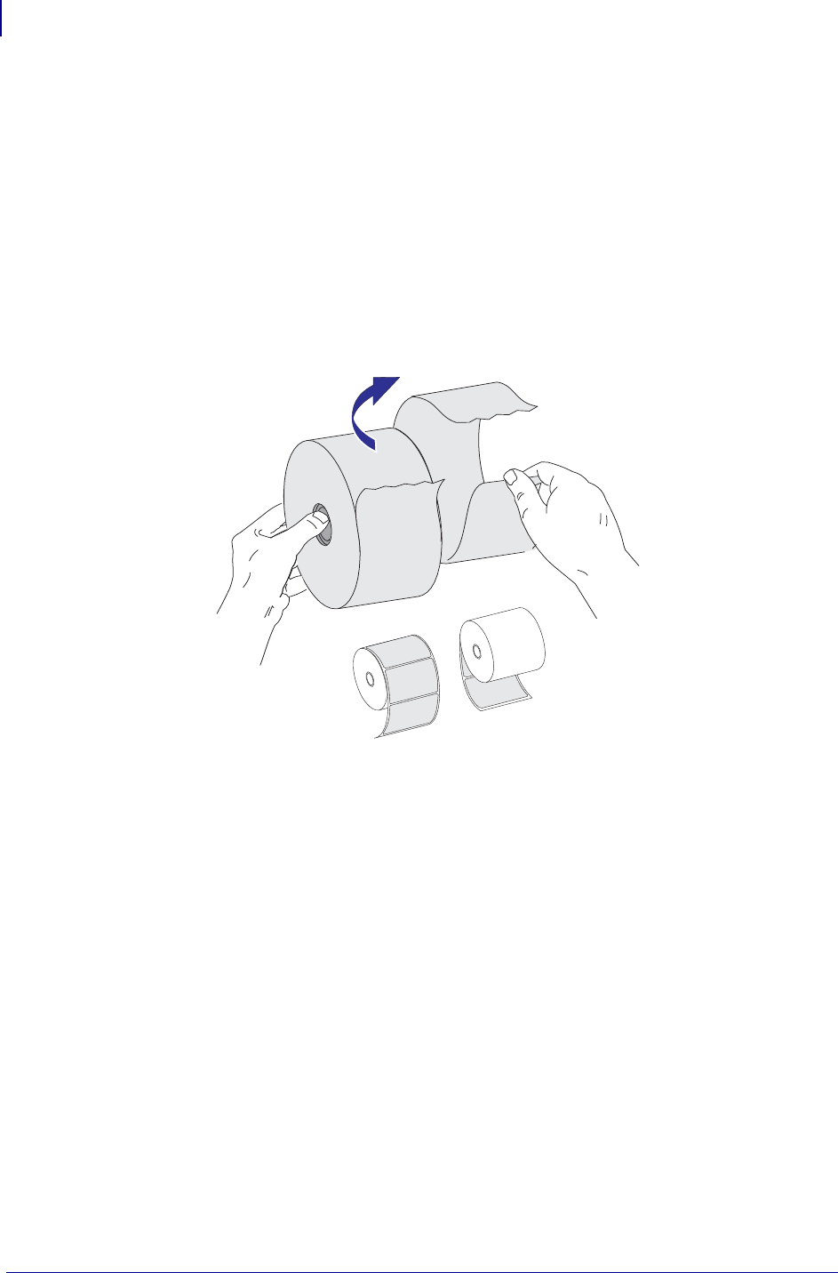
Preparing and Handling Media
Carefully handling and storing media is important for the print quality in addition to using the
right media (such as Genuine Zebra™ Supplies) and the right printer, your Zebra ZD500
Series™ printer. If the media becomes contaminated or dirty, it can damage or degrade the
printhead or the printer, as well as, cause defects in the printed image (voids, streaks,
discoloration, compromise the adhesive, etc.).
During manufacturing, packaging, handling and storage, the outside length of media may
become dirty or contaminated when handled or dusty when stored. To prevent this type of
contamination, we ask you to remove the outside layer of the media roll or stack. This will
remove any contaminates or adhesive from labels or tape used to secure the media to the roll
that may transfer to the printer or printhead.
Media Storage Tips
• Store media in a clean, dry, cool, dark area.
• Direct thermal media is chemically treated to be heat sensitive. Direct sunlight or heat
sources may ‘expose’ the media.
• Do not store media with chemicals or cleaning products.
• Leave media in its protective packaging until it is to be placed in the printer for use.
• Many media types and label adhesives have a ‘shelf life’ or expiration date. Always
use the oldest, viable (non-expired) media first.

19
Setup
Setting the Printer Menu and Report Display Language
1/16/2014 ZD500 Series™ Thermal Transfer Printer User’s Guide P1062653-002 Rev. A
Setting the Printer Menu and Report Display Language
The printer supports many languages for menu display, time and date format, and
configuration reports.
The primary method used to configure language is the control panels menu. Use the following
procedure to set your printer’s language when the printer is turned on and in the ‘Ready’ state.
1. Press the menus ‘Home’ ( ) button.
2. Navigate to the ‘LANGUAGE’ ( ) menu button and press the ‘Select’ () button.
3. Use the ‘Up’ () and ‘Down’ () navigation arrows to browse the languages.
4. Stop browsing when you have found the language you wish to use for operating the
printer. The language displayed will be your selected language.
Set Media Print Method
Set the printer’s PRINT METHOD using the printer control panel. See SETTINGS Menu
on page 52 - PRINT METHOD for the full procedure.
The ZD500 Series™ printer has been designed to print with DIRECT THERMAL (direct
thermal media which uses heat sensitive media to print) or THERMAL TRANS (thermal
transfer printing which uses ribbon to heat transfer print to the media).
The direct thermal and thermal transfer settings each have optimized Darkness control
characteristics to allow similar visual Darkness and Print Quality at the same DARKNESS and
PRINT SPEED settings.
Setup
Loading Roll Media
20
P1062653-002 Rev. A ZD500 Series™ Thermal Transfer Printer User’s Guide 1/16/2014
Loading Roll Media
Use the instructions in this section to load roll media in Tear-Off mode and Gap/Web media
sensing set by default. This mode also works for most full width black mark (black line)
media.
For other common media and setting variations see one of the following:
•Using the Movable Black Mark Sensor on page 89
•Printing on Fan-Fold Media on page 93
•Cutter Option on page 103
•Label Dispenser Option on page 100 after you have loaded media using this
procedure.
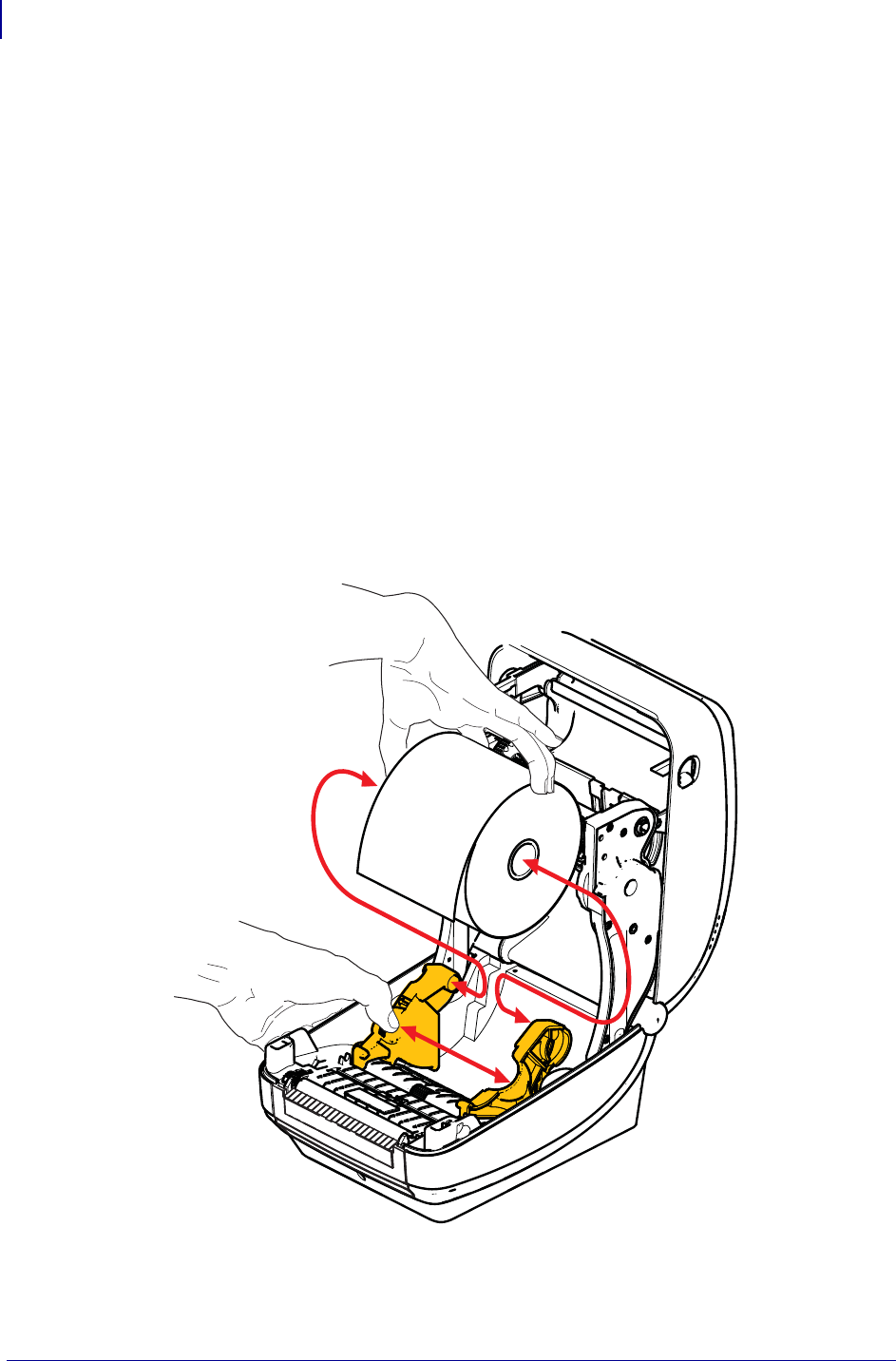
Instructions for media loading:
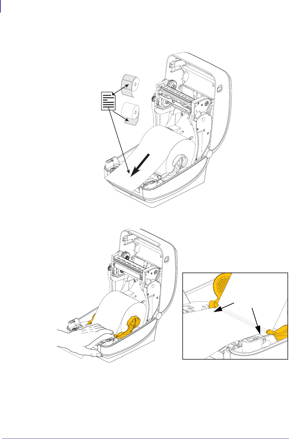
1. Open the printer. Pull the release latch levers toward the front of the printer.
2. Open the media roll holders. Pull the media guides open with your free hand and place the
media roll on the roll holders and release the guides. Orient the media roll so that its
printing surface will face up as it passes over the platen (drive) roller.
21
Setup
Loading Roll Media
1/16/2014 ZD500 Series™ Thermal Transfer Printer User’s Guide P1062653-002 Rev. A
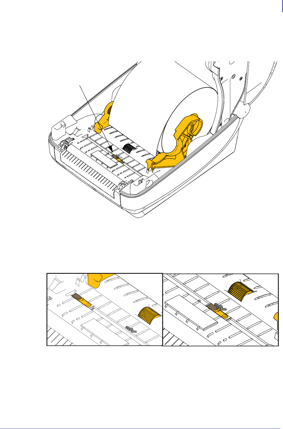
3. Verify that the movable black mark sensor is aligned in the center default position. This is
the standard operating position for media sensing. When the sensor is moved from the
default label web (gap) sensing area, the printer will only detect black mark and die-cut
notched media.
Movable
Black Mark Sensor
Off Center
Black Mark Sensing Only
Default - Web (Gap) Sensing
Standard Operating Position
Setup
Loading Roll Media
22
P1062653-002 Rev. A ZD500 Series™ Thermal Transfer Printer User’s Guide 1/16/2014
4. Pull the media so that it extends out of the front of the printer. Verify the roll turns freely.
The roll must not sit in the bottom of the media compartment. Verify that the media’s
printing surface is facing up.
5. Push the media under both of the media guides.
6. Close the printer. Press down until the cover snaps closed.
Your media may need a ‘Manual Calibration’ to adjust the printer’s sensors and label length
setting to operate properly. See the Manual Calibration - Media on page 75. If you are using
RFID media, run a RFID Calibration procedure, see the RFID Menu on page 65 - RFID
CALIBRATE for details.
Under Media
Guides
23
Setup
Loading Transfer Ribbon
1/16/2014 ZD500 Series™ Thermal Transfer Printer User’s Guide P1062653-002 Rev. A
Loading Transfer Ribbon
Transfer ribbons come in several varieties and in some cases colors to match your application
needs. Genuine Zebra® transfer ribbons are specifically designed for your printer and Zebra
brand media. Using non-Zebra media or ribbons not approved for use in your Zebra® printer
may damage your printer or printhead.
• The media and ribbon types should be matched to provide you with optimal print results.
• Always use ribbon that is wider than the media to protect the printhead from wear.
• For direct thermal printing, do not load ribbon in the printer.
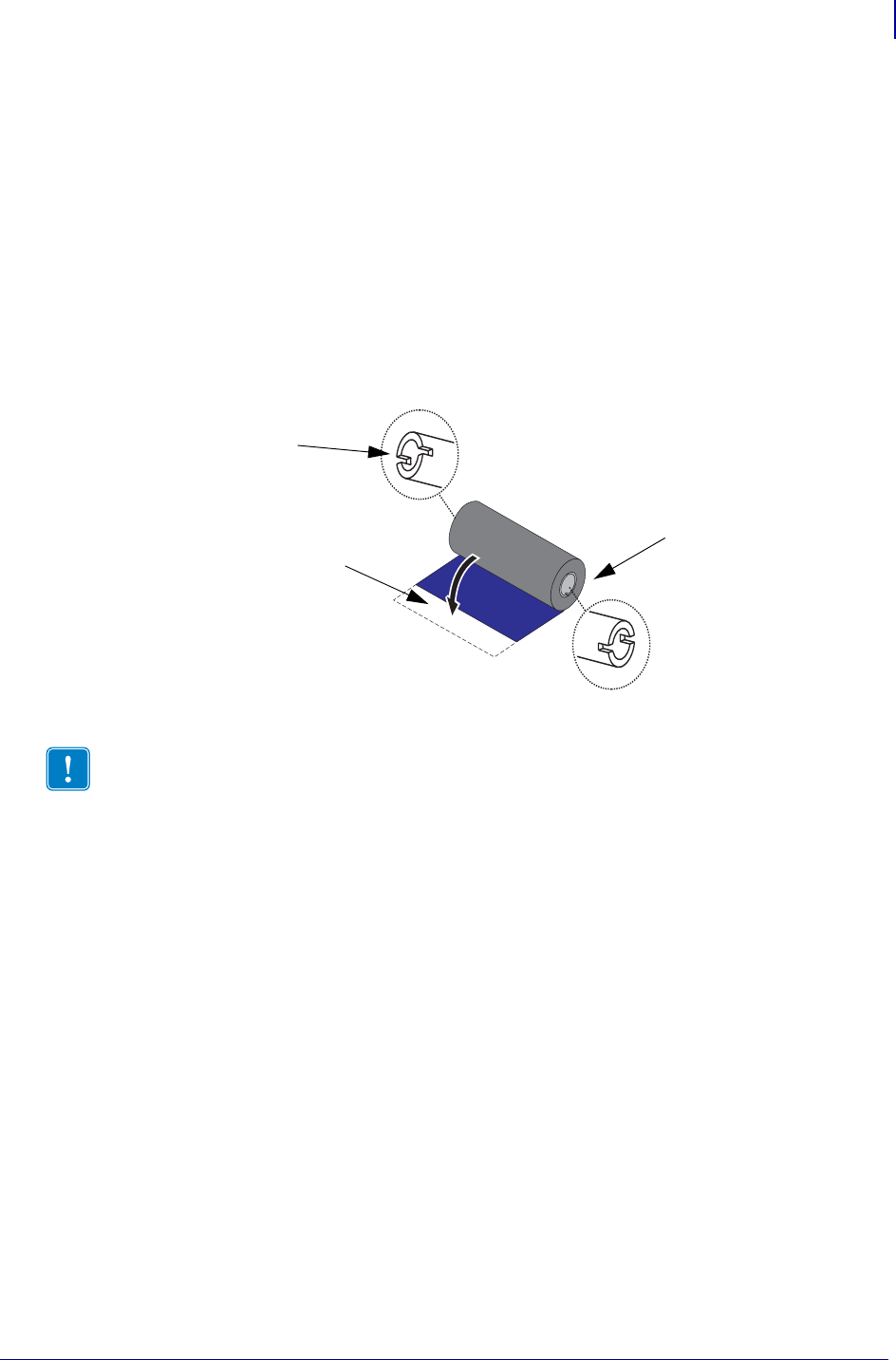
Before following these steps, prepare the ribbon by removing its wrapping and pulling its
adhesive strip free.
Notch
Adhesive Strip
Right Side
(printer and roll)
Important • DO NOT USE early model desktop printer ribbon cores! The older ribbon cores
can be identified by notches on only one side of the ribbon core. These older cores are too large
and will cause take-up spool to bind.
Note • DO NOT USE ribbon cores with damaged notches - rounded, frayed, smashed, etc. The
core notches should be square to lock the core on the spindle or the core may slip causing
ribbon wrinkle, poor end of ribbon sensing or other intermittent failures.
Setup
Loading Transfer Ribbon
24
P1062653-002 Rev. A ZD500 Series™ Thermal Transfer Printer User’s Guide 1/16/2014
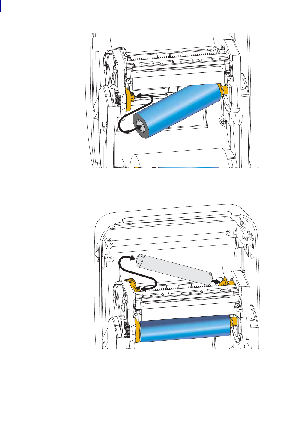
1. With the printer open, place a new ribbon roll on printer’s lower ribbon supply spindles.
Rotate the roll until the notches align and lock into the left side of the supply hub.
2. Place an empty ribbon core on printer’s take-up spindles. Rotate the ribbon core until the
notches align and lock into the left side of the take-up hub.
You can find your first ribbon take-up core in the packing box. Subsequently, use the
empty supply core to take up the next roll of ribbon.
25
Setup
Loading Transfer Ribbon
1/16/2014 ZD500 Series™ Thermal Transfer Printer User’s Guide P1062653-002 Rev. A
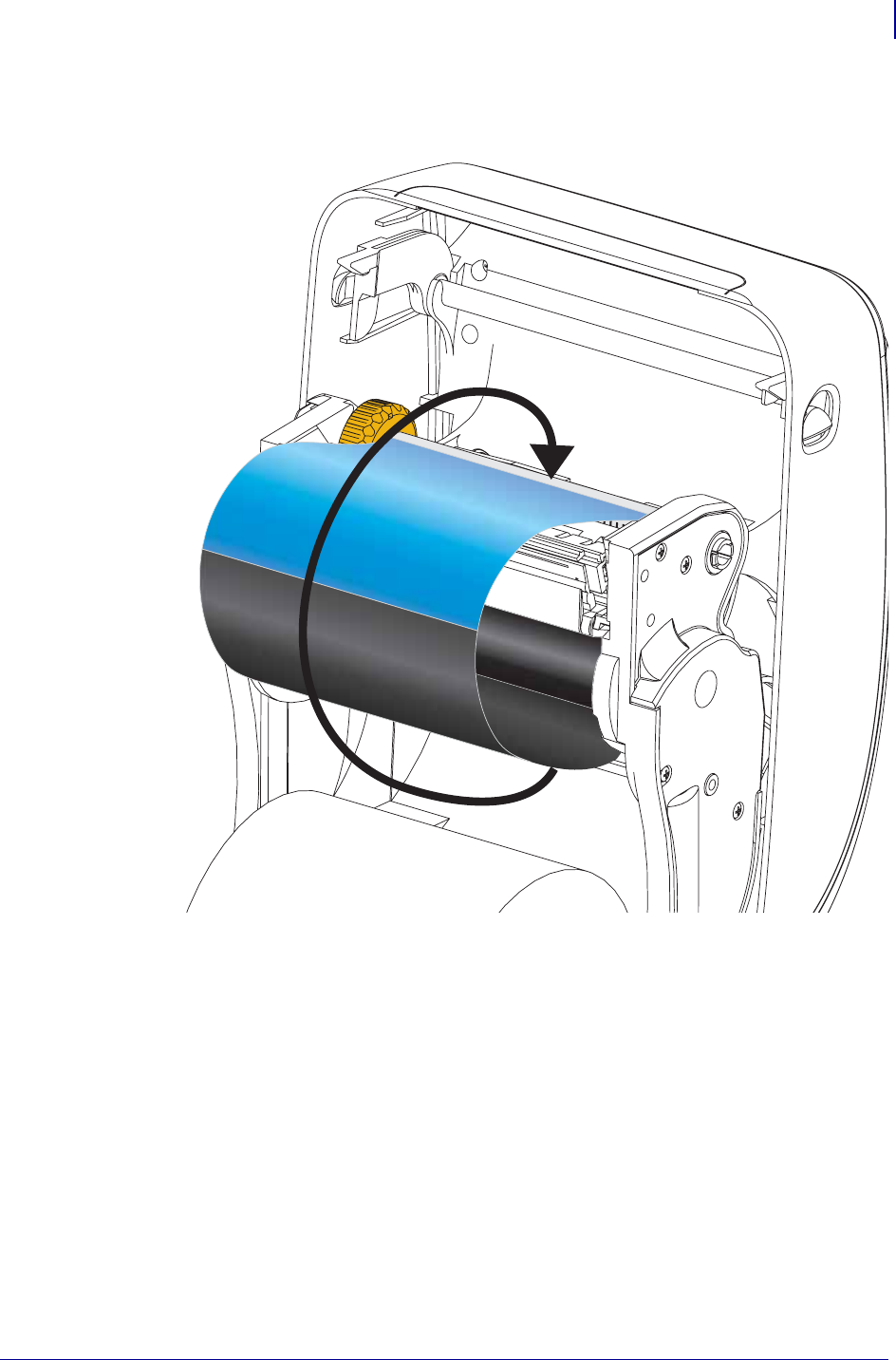
3. Pull the transfer ribbon’s leader off the roll and attach it with the adhesive strip on the
leader to the empty ribbon core on the take-up spindle. Center the ribbon on the ribbon
core.
Setup
Loading Transfer Ribbon
26
P1062653-002 Rev. A ZD500 Series™ Thermal Transfer Printer User’s Guide 1/16/2014
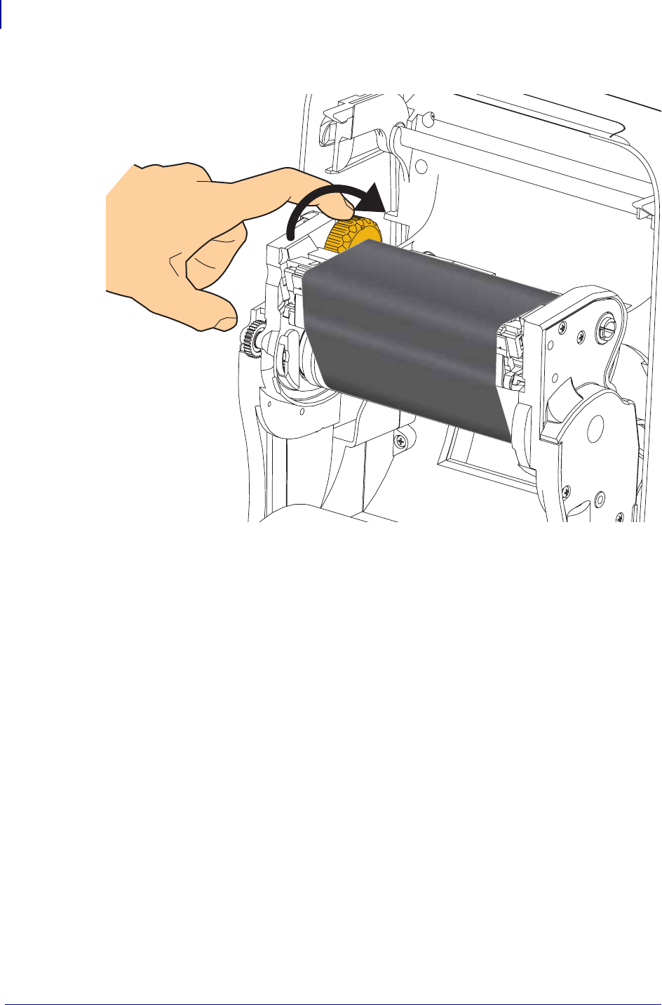
4. Rotate the thumb wheel on the left side of the supply spindle towards the rear of the
printer until the ribbon is pulled tight across the printhead.
5. Verify that the media is loaded and ready to print and then close the printer cover.
6. Press the Feed button to have the printer feed a minimum of 10 cm (4 inches) of media to
remove slack and ribbon wrinkle, and to align the ribbon on the spindles.
7. Change the print mode setting from direct thermal printing to thermal transfer to set the
printer’s temperature profiles for thermal transfer media. This can be done with the printer
driver, application software, or printer programming commands.
• When controlling printer operations with ZPL programming, refer to the Media Type
(^MT) ZPL II command (follow the instructions in the ZPL Programming Guide).
8. To verify the mode change from direct thermal printing to thermal transfer printing, use
the Test Printing with Configuration Report Printouts on page 27 to print a configuration
label. The ‘PRINT METHOD’ should read ‘THERMAL-TRANS’ on the printer
configuration status label.
Your printer is now ready to print.
Your media may need a ‘Manual Calibration’ to adjust the printer’s sensors and label length
setting to operate properly. See the Manual Calibration - Media on page 75. If you are using
RFID media, run a RFID Calibration procedure, see the RFID Menu on page 65 - RFID
CALIBRATE for details.
27
Setup
Test Printing with Configuration Report Printouts
1/16/2014 ZD500 Series™ Thermal Transfer Printer User’s Guide P1062653-002 Rev. A
Test Printing with Configuration Report Printouts
Before you connect the printer to your computer, make sure that the printer is in proper
working order. You can do this by printing a configuration status report.
1. Make sure the media is properly loaded and the top cover of the printer is closed.
2. Press and hold CANCEL button while setting the printer power switch to on (I).
3. Hold CANCEL button down until the printer status light turns green for the first time and
release.
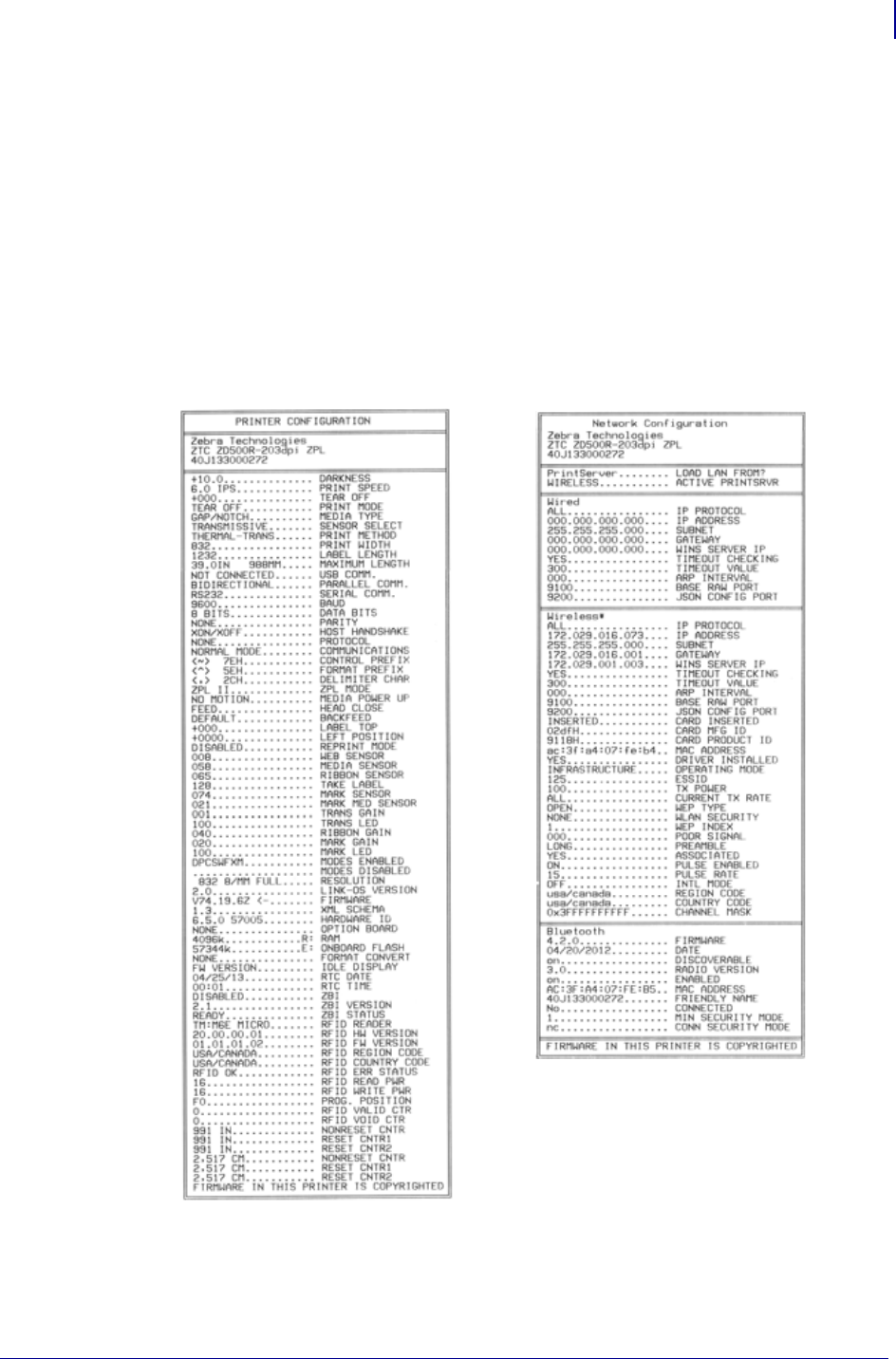
4. The Printer and Network Configuration Reports (below) will be printed a couple of
seconds after the printer’s display reports ‘PRINTER READY’.
If you cannot get these reports to print and you have checked your printer installation with this
document, then see the Troubleshooting section of the User’s Guide or the Zebra Website for
guidance.
Setup
Connecting your Printer to a Computer
28
P1062653-002 Rev. A ZD500 Series™ Thermal Transfer Printer User’s Guide 1/16/2014
Connecting your Printer to a Computer
The printer supports a variety of interface options and configurations. These include:
Universal Serial Bus (USB) interface, RS232 Serial, Parallel (IEEE 1284.4), 10/100 Wired
Ethernet, and an optional internal Wireless Ethernet (WiFi) and Bluetooth radio.
Pre-install Windows® Printer Drivers
Install the Zebra Setup Utilities before applying power to the printer connected to the PC
(running a Zebra driver supported Windows operating system). The Zebra Setup Utility will
prompt you to apply the printer power. Continue to follow the instructions to complete your
printer installation.
The Zebra Setup Utility is designed to assist you with installing these interfaces. The
cabling and unique parameters for each of these physical printer communication interfaces is
discussed in the following pages to assist you with making configuration setup choices prior to
and immediately following applying power. The Zebra Setup Utilities configuration wizards
will instruct you to turn the printer’s power on at the appropriate time to complete the
installation of your printer.
For more details on installing Ethernet (network) and Bluetooth interfaces:
•ZebraNet® Wired and Wireless Print Servers User Guide
Interface Cable Requirements
Data cables must be of fully shielded construction and fitted with metal or metallized
connector shells. Shielded cables and connectors are required to prevent radiation and
reception of electrical noise.
To minimize electrical noise pickup in the cable:
• Keep data cables as short as possible (6 foot [1.83 m] recommended).
• Do not tightly bundle the data cables with power cords.
• Do not tie the data cables to power wire conduits.
.
Caution • Keep the power switch in the OFF position when attaching the interface cable.
The power cord must be inserted into the power supply and the power receptacle on the
back of the printer before connecting or disconnecting the communications cables.
Important • This printer complies with FCC “Rules and Regulations,” Part 15, for Class B
Equipment, using fully shielded data cables. Use of un-shielded cables may increase radiated
emissions above the Class B limits.
29
Setup
Connecting your Printer to a Computer
1/16/2014 ZD500 Series™ Thermal Transfer Printer User’s Guide P1062653-002 Rev. A
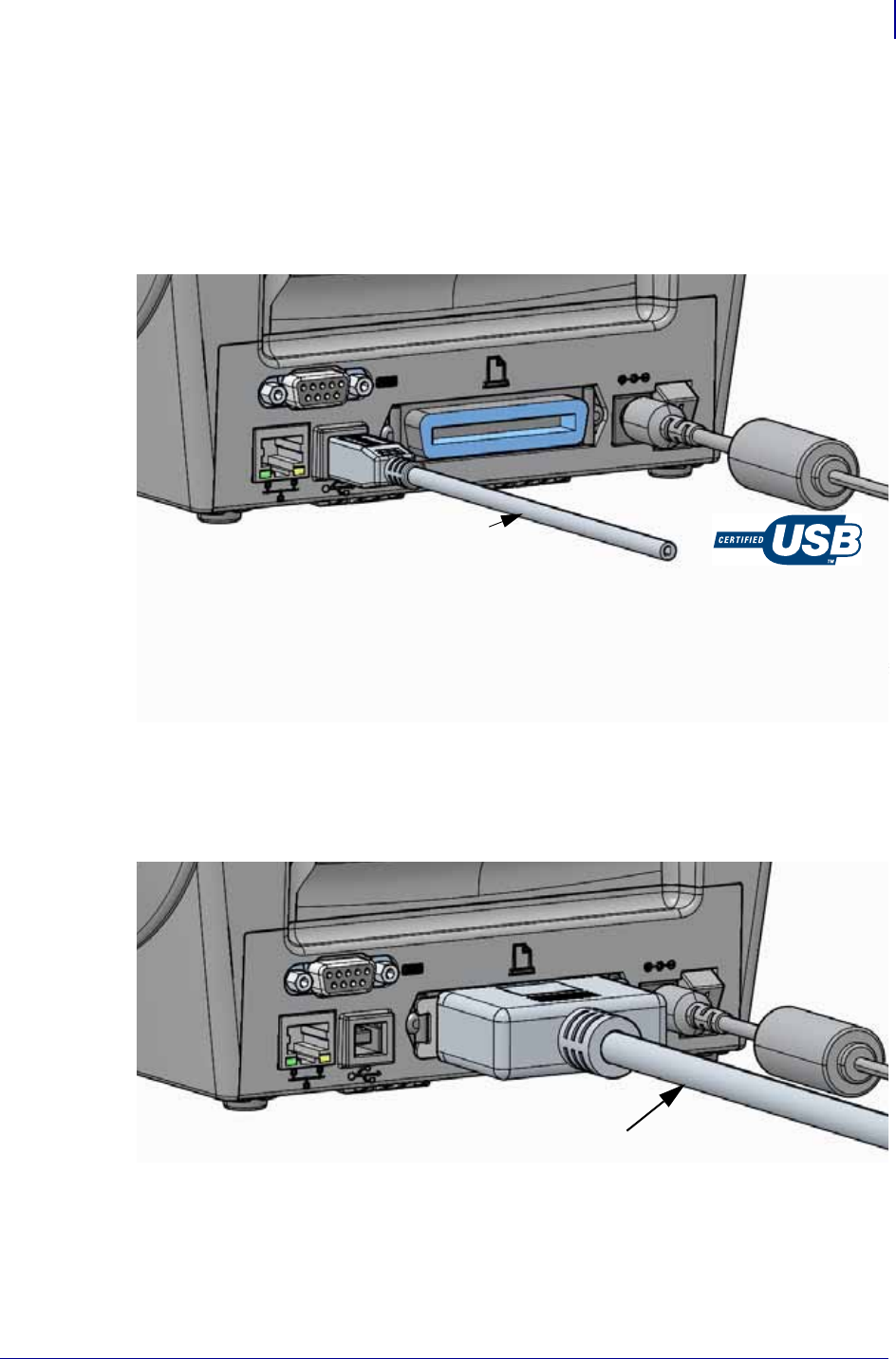
USB Interface
Universal Serial Bus (version 2.0 compliant) provides a fast interface that is compatible with
your existing PC hardware. USB’s “plug and play” design makes installation easy. Multiple
printers can share a single USB port/hub.
When using a USB cable (not supplied with your printer), verify that the cable or cable
packaging bears the “Certified USB™” mark (see below) to guarantee USB 2.0 compliance.
.
Parallel Interface
The required cable must have a 25 pin “D” type (DB-25P) male connector on one and a
Centronics on the other end (IEEE 1284 A-B parallel interface specification).
USB Cable
Parallel Cable
Setup
Connecting your Printer to a Computer
30
P1062653-002 Rev. A ZD500 Series™ Thermal Transfer Printer User’s Guide 1/16/2014
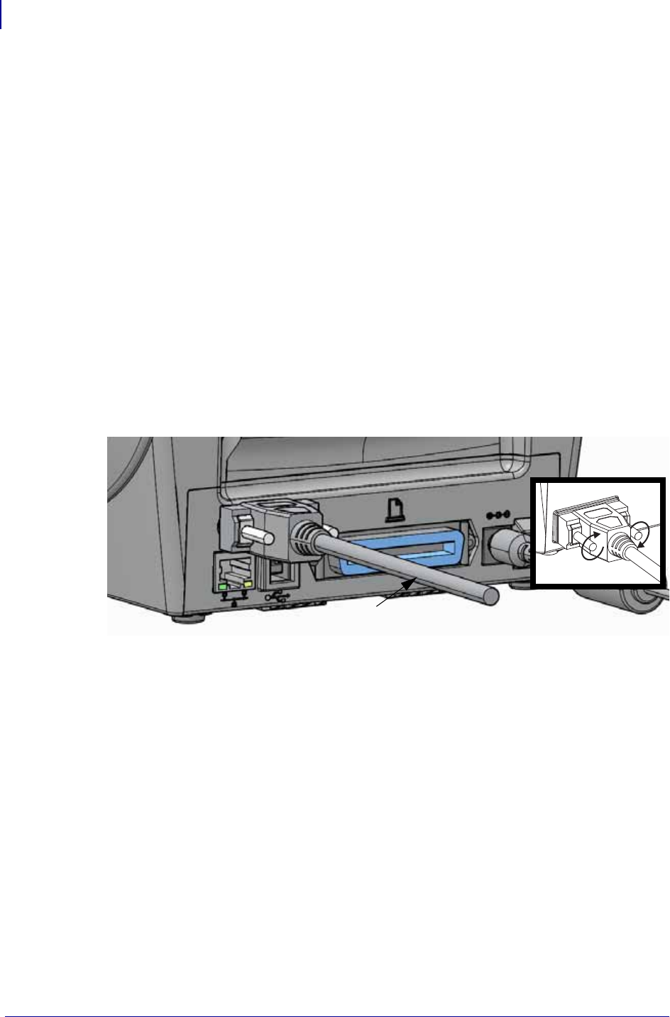
Serial Interface
The printer uses a Null Modem (cross-over) cable for DTE communications. The required
cable must have a nine-pin “D” type (DB-9P) male connector on one end which plugs into the
mating (DB-9S) serial port located on the back of the printer. The other end of this signal
interface cable connects to a serial port on the host computer. For pinout information, refer to
Appendix A.
The serial port communication settings between the printer and host (typically a PC) must
match for reliable communication. The Bits per second (or Baud rate) and Flow control are the
most common settings that get changed.
Serial communications between the printer and the host computer can be set by:
• Using the printers Control Panel ‘PORTS’ menu.
• ZPL programming ^SC command
• Resetting the printer to its default printer configuration.
Factory defaults for serial communication settings are: 9600 baud, 8 bit word length, NO
parity, 1 stop bit, and XON/XOFF (‘Software’ data flow control in the Windows based host
system).
Tighten
Serial Cable

31
Setup
Connecting your Printer to a Computer
1/16/2014 ZD500 Series™ Thermal Transfer Printer User’s Guide P1062653-002 Rev. A
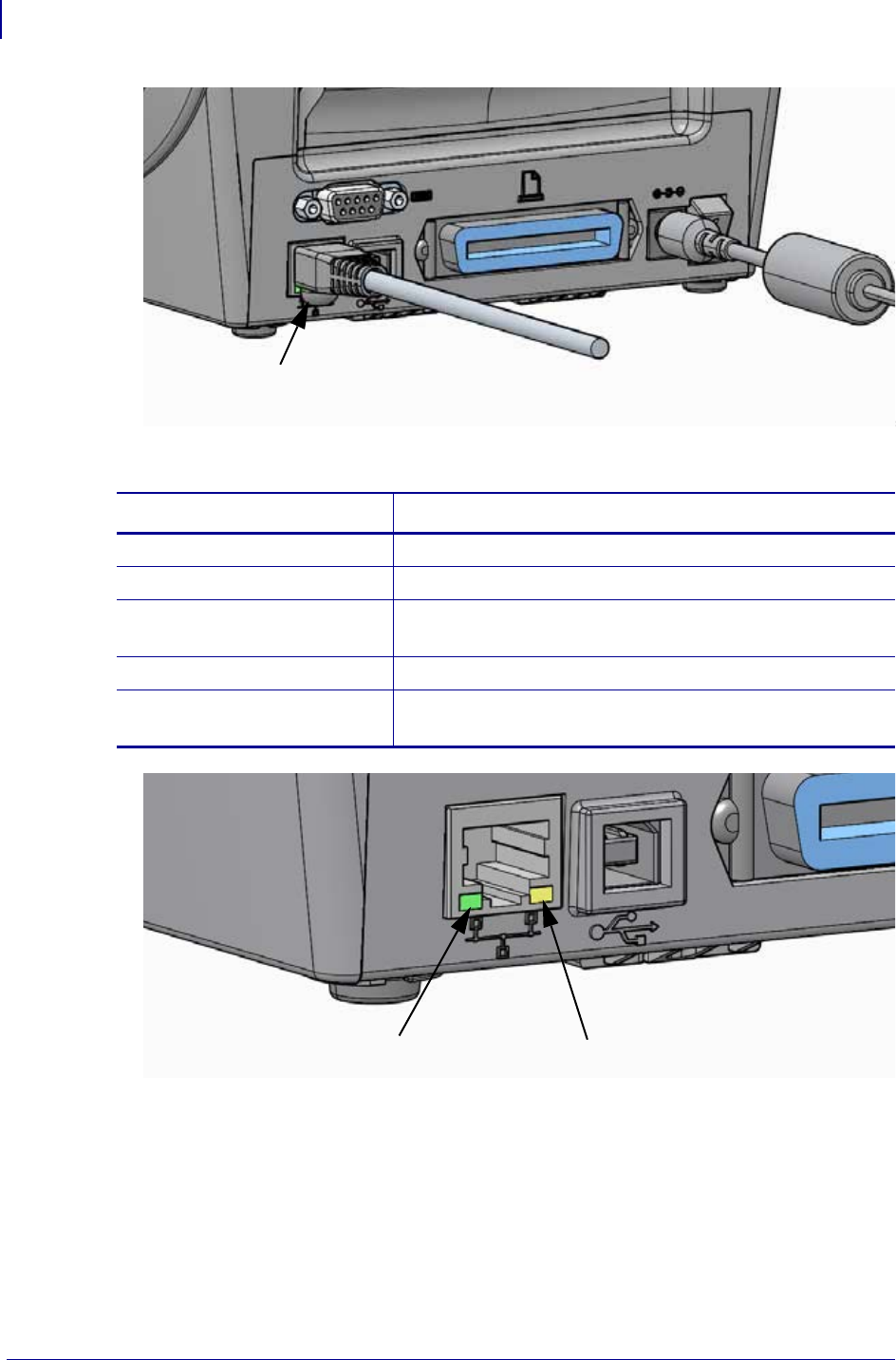
Wired (Ethernet) Interface
The printer requires UTP RJ45 Ethernet cable rated CAT-5 or better.
The printer has a built-in network print server. For more information on configuring your
printer to run on a compatible Ethernet based network, see the ZebraNet® Wired and Wireless
Print Server users guide. The printer must be configured to run on your LAN (local area
network) or WAN (wide area network). The print server on board your printer can be accessed
through the printer’s print server Web pages.
Assigning a IP Address for Network Access All devices on a Ethernet network
require a network IP (Internet Protocol) address. The printer’s IP address is needed to access
the printer for printing and printer configuration. The four different ways to assign an IP
address are:
• DHCP (Dynamic Host Connection Protocol) - Default setting
• ZebraNet Bridge
• Using the printer’s Control Panel ‘NETWORK’ menu
•Telnet
• Zebra Setup Utilities (includes the ZebraDesigner Windows printer driver)
DHCP for Personal Networks The printer by default is set to operate on LAN or WAN
with DHCP by default to aid end-user installations. This is intended primarily for personal
networks. The network automatically provides a new network IP address each time the printer
is turned on. The Windows printer driver uses a Static IP address to connect to the printer. The
IP address set in the printer driver will need to be changed to access the printer if its assigned
IP address has changed after the printer’s initial installation.
Managed Networks Using the printer in a structured network (LAN or WAN) requires a
network administrator to assign the printer a Static IP address and other settings needed to
operate on the network properly.
Viewing the Printer’s IP Address Use the printer’s control panel to access the Ethernet
settings in your printer.
1. Press the menus ‘Home’ ( ) button.
2. Navigate to the ‘NETWORK’ ( ) menu button and press the ‘Select’ () button.
3. Use the ‘Up’ () and ‘Down’ () navigation arrows to browse to the
‘WIRED IP ADDRESS’ setting. You can read the assigned IP address or set the IP
address. The printer’s default address (all 0’s - zeros) is not a valid address. With
assistance of your network administrator, you can set all of the ‘WIRED’ network setting
in this ‘NETWORK’ menu branch.
Setup
Connecting your Printer to a Computer
32
P1062653-002 Rev. A ZD500 Series™ Thermal Transfer Printer User’s Guide 1/16/2014
Ethernet Status/Activity Indicators
Print Server - Default User ID and Password
There are some features that require the default User ID and/or default password to access
printer’s print server or if you have the Wi-Fi option in the printer. The Factory Default Values
are shown below:
•User ID: admin
•Password: 1234
Ethernet Cable
(RJ45 Connector)
LED Status Description
Both OFF No Ethernet link detected
Green 100 Mbps link detected
Green with the Amber
flickering on and off
100 Mbps link and Ethernet activity detected
Amber 10 Mbps link detected
Amber with the Green
flickering on and off
10 Mbps link and Ethernet activity detected
Green LED Amber LED

33
Setup
ZebraNet® Internal Wireless Print Server Option
1/16/2014 ZD500 Series™ Thermal Transfer Printer User’s Guide P1062653-002 Rev. A
ZebraNet® Internal Wireless Print Server Option
This section covers basic configuration of your ZebraNet Internal Wireless Print Server option
for operation. For more detailed information, refer to the ZebraNet Wired and Wireless Print
Servers User Guide.
You may configure your printer for wireless operation in the following ways. This basic guide
covers only the first option, the Connectivity Wizard.
•Through the Connectivity Wizard, which writes a ZPL script for you. On the last screen
of the utility, you may choose to send the command directly to your printer, or you may
choose to save the ZPL script to a file. The saved ZPL file has several purposes:
• The file can be sent to the printer through any available connection (serial, parallel,
USB, or wired print server).
• The file can be resent to the printer after the network settings have been restored to
factory defaults.
• The file can be sent to multiple printers that will use the same network settings.
•Through ZPL script that you write yourself. Use the ^WX command to set the basic
parameters for security type. You can send the command through any available connection
(serial, parallel, USB, or wired print server). Refer to the ZPL Programming Guide for
more information on this option.
•Through Set/Get/Do (SGD) commands that you send to the printer. Begin with
wlan.security to set the wireless security type. Depending on which security type
that you select, other SGD commands will be necessary to specify other parameters. You
can send the commands through any available connection (serial, parallel, USB, or wired
print server). Refer to the ZPL Programming Guide for more information on this option.
Important • A wireless option board must be installed on your printer before you can
configure the printer to communicate using the wireless radio option.
Setup
Configure Using the Connectivity Wizard
34
P1062653-002 Rev. A ZD500 Series™ Thermal Transfer Printer User’s Guide 1/16/2014
Configure Using the Connectivity Wizard
The ZebraNet Bridge Enterprise utility resides on the User CD for your printer and is available
through http://www.zebra.com/software. ZebraNet Bridge Enterprise version 1.2.5 or later is
required to configure the printer correctly for use.
The Connectivity Wizard, which is part of this software, allows you to configure your printer
easily for wireless operation by writing the appropriate ZPL script for you. Use this utility
when you are first installing the wireless print server or after you set the network options back
to factory defaults.
To use the Connectivity Wizard, complete these steps:
1. If it is not already installed, install ZebraNet Bridge Enterprise on your computer.
You can get the program from the user CD that came with your printer, or you can
download it at http://www.zebra.com/software.
2. Launch the ZebraNet Bridge Enterprise program.
If you are prompted for a serial number, you may click Cancel. You will still be able to
use the Connectivity Wizard.
3. From the Menu bar, select Tools > Connectivity Wizard.
The Connectivity Wizard opens.
Note • You can only set up one print server at a time with the Connectivity Wizard. To
configure multiple print servers (wired and wireless), run the program once for each print
server.
35
Setup
Configure Using the Connectivity Wizard
1/16/2014 ZD500 Series™ Thermal Transfer Printer User’s Guide P1062653-002 Rev. A
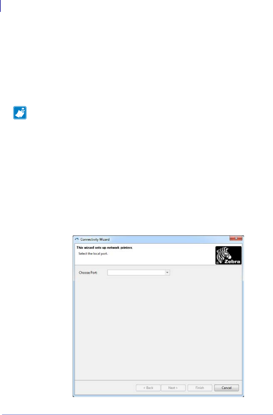
4. From the Choose Port list, select the port to which your printer is connected.
• If you will save the file without sending it to the printer, you may select any available
port.
• If you select File:, you will be asked to browse to the location of the file you want to
save.
• If you select a serial port, the serial configuration information appears below the
Choose Port list. If necessary, change the serial communication settings to match your
printer’s settings.
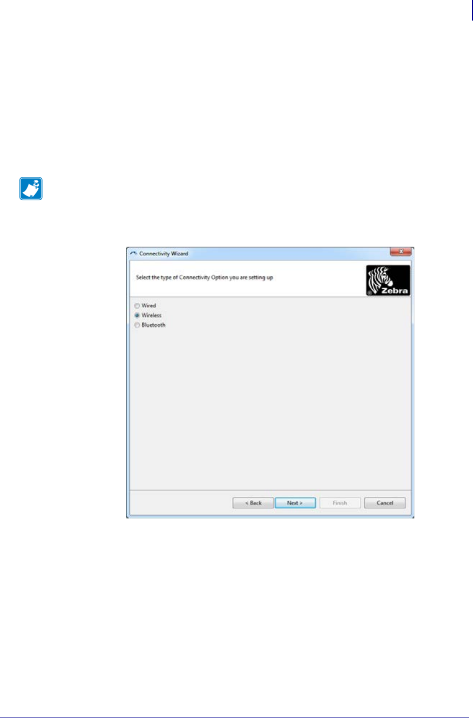
5. Click Next.
The wizard prompts for the print server device to configure.
6. Select Wireless and then click Next.
The wizard prompts you for the type of printer you are using.
Note • If a port is in use by another device, it will not be included in the drop-down
list.
Setup
Configure Using the Connectivity Wizard
36
P1062653-002 Rev. A ZD500 Series™ Thermal Transfer Printer User’s Guide 1/16/2014
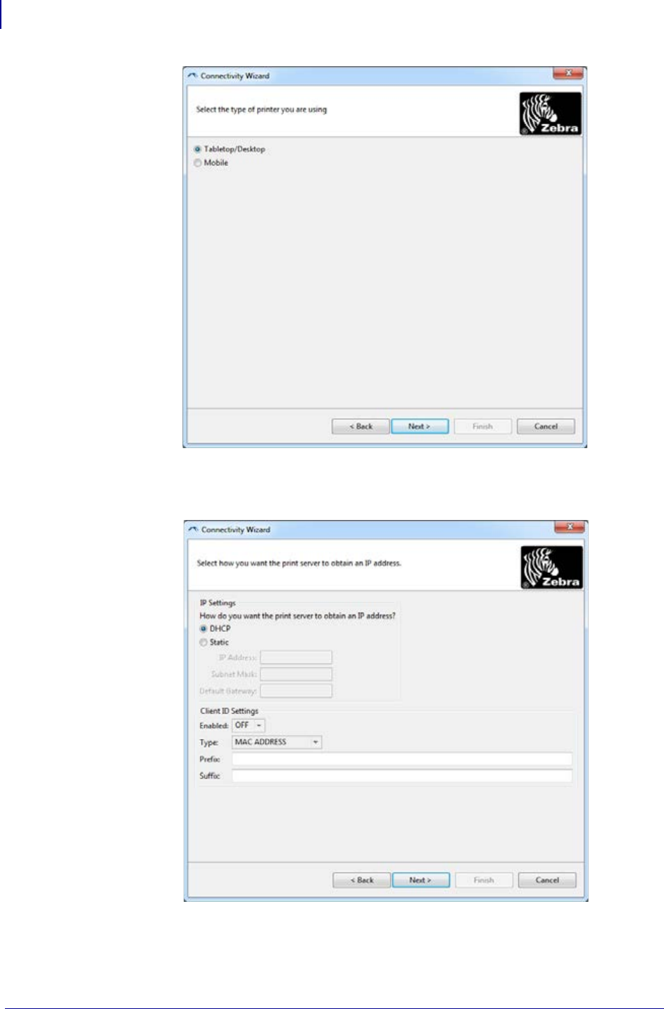
7. Select the type of printer you are using and then click Next.
The wizard prompts for the wireless IP information.
37
Setup
Configure Using the Connectivity Wizard
1/16/2014 ZD500 Series™ Thermal Transfer Printer User’s Guide P1062653-002 Rev. A
8. Enable the DHCP (dynamic) or static IP option.
9. Click Next.
The Wireless Settings window opens.
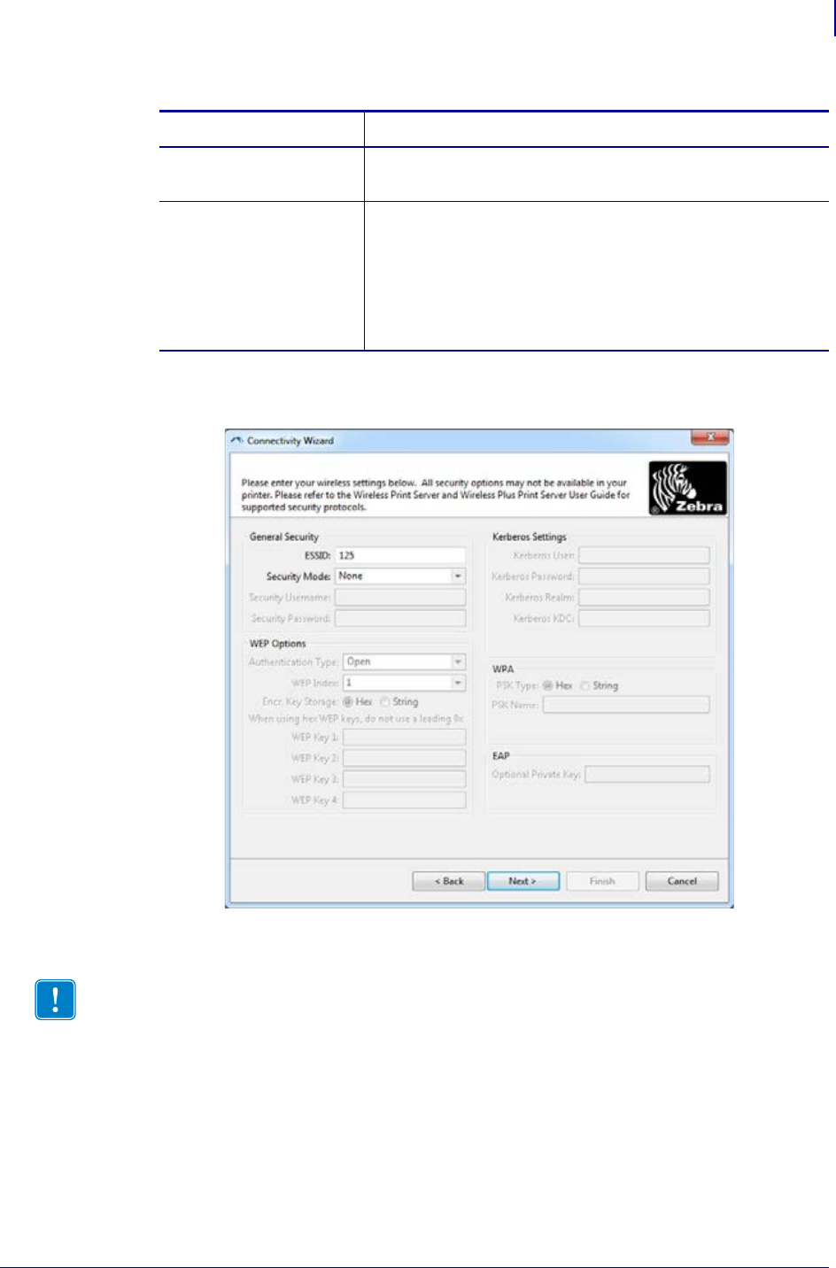
10. Enter the ESSID.
If you will be using... Complete the following steps...
DHCP a. Select DHCP and click Next.
b. Continue with step 9.
Static a. Select Static.
The IP settings fields are activated.
a. Enter the IP Address, Default Gateway, and Subnet
Mask for the wireless print server. Contact your network
administrator for the correct values.
b. Continue with step 9.
Important • The ESSID and pass phrase, if used, must be set at your access point before
completing these steps.

Setup
Configure Using the Connectivity Wizard
38
P1062653-002 Rev. A ZD500 Series™ Thermal Transfer Printer User’s Guide 1/16/2014
11. From the drop-down, select your Security Mode.
If you select… Then…
None Continue with step 12.
WEP 40-Bit
WEP 128-Bit
a. In the WEP Options section of the window, enter the
following values:
•Authentication type
•WEP Index
•Encryption Key Storage
•WEP Keys
b. Click Next and continue with step 12.
EAP-TLS
EAP-TTLS
EAP-FAST
WPA-EAP-TLS
In the EAP section of the window, if necessary:
a. Enter the Optional Private Key.
b. Click Next and continue with step 12.
PEAP
LEAP
WPA-EAP-TTLS
WPA-PEAP
WPA-LEAP
In the General Security section of the window:
a. Enter the Security Username and Password.
b. Click Next and continue with step 12.
WPA-PSK In the WPA section of the window:
a. Select the PSK Type.
b. Enter the PSK Name.
c. Click Next and continue with step 12.
WPA-EAP-FAST a. In the General Security section of the window, enter the
Security Username and Password.
b. In the EAP section of the window, if necessary, enter the
Optional Private Key.
c. Click Next and continue with step 12.
KERBEROS a. In the Kerberos Settings section of the window, enter the
following values:
•Kerberos User
•Kerberos Password
•Kerberos Realm
•Kerberos KDC
b. Click Next and continue with step 12.
c.KERBEROS is not supported on Internal
Wireless Plus print servers or radio cards.
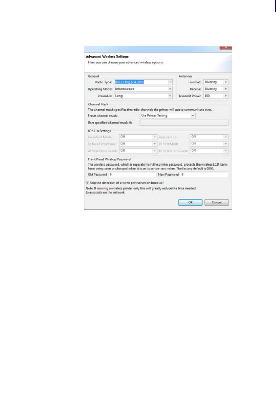
39
Setup
Configure Using the Connectivity Wizard
1/16/2014 ZD500 Series™ Thermal Transfer Printer User’s Guide P1062653-002 Rev. A
12. Click Advanced Options in the Wireless Settings window. step 12
The Advanced Wireless Settings window opens.
13. Review the settings in the Advanced Wireless Settings window. Change the settings as
necessary, and then click OK.
The Wireless Settings window returns.
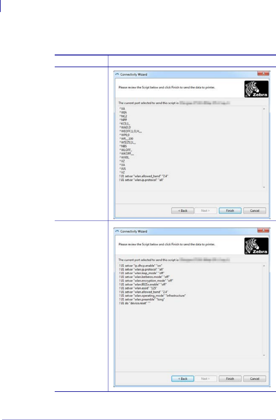
Setup
Configure Using the Connectivity Wizard
40
P1062653-002 Rev. A ZD500 Series™ Thermal Transfer Printer User’s Guide 1/16/2014
14. Click Next.
Based on your selections in the Wireless Setup Wizard, the program writes the appropriate
ZPL commands and displays them for your review.
If you selected… Then a dialog box similar to this displays.
Tabletop/Desktop
Mobile

41
Setup
Configure Using the Connectivity Wizard
1/16/2014 ZD500 Series™ Thermal Transfer Printer User’s Guide P1062653-002 Rev. A
15. Determine if you will send the script immediately, or save it for use at a later time.
16. Observe the wireless status on the printer’s control panel, and confirm that you have set up
your printer for wireless connectivity. Printers that have an LCD display text or symbols
(see Table 5 and Table 6).
To... Then...
Complete setup by sending
the ZPL script to the printer
through the port selected at
the beginning of this
procedure
a. Verify that the printer is connected to the computer
through the port you selected.
Note • For serial connections, use a serial null
modem cable.
b. If you have not already done so, turn on (I) the printer.
c. On the Review and Send ZPL for Wireless window,
click Finish.
The printer sends the ZPL script to the printer through
the selected port. The Wireless Setup Wizard screen
closes.
d. Turn the printer off (O) and then back on (I).
Save the ZPL script to a file
for later use or for use on
other printers
Note • You can send the ZPL script file to
multiple printers that use the same configuration,
or you can send the file to a printer that had the
network settings restored to the factory defaults.
This saves you from having to go through the
Wireless Setup Wizard more than once.
a. On the Review and Send ZPL for Wireless window,
highlight the script, right-click, and select Copy.
b. Open a text editor, such as Notepad, and paste the
script into the application.
c. Save the script.
d. In the Connectivity Wizard, click Cancel to exit
without sending the script at this time.
e. If you have not already done so, turn on (I) the printer.
f. Send the ZPL file to the printer through the connection
of your choice.
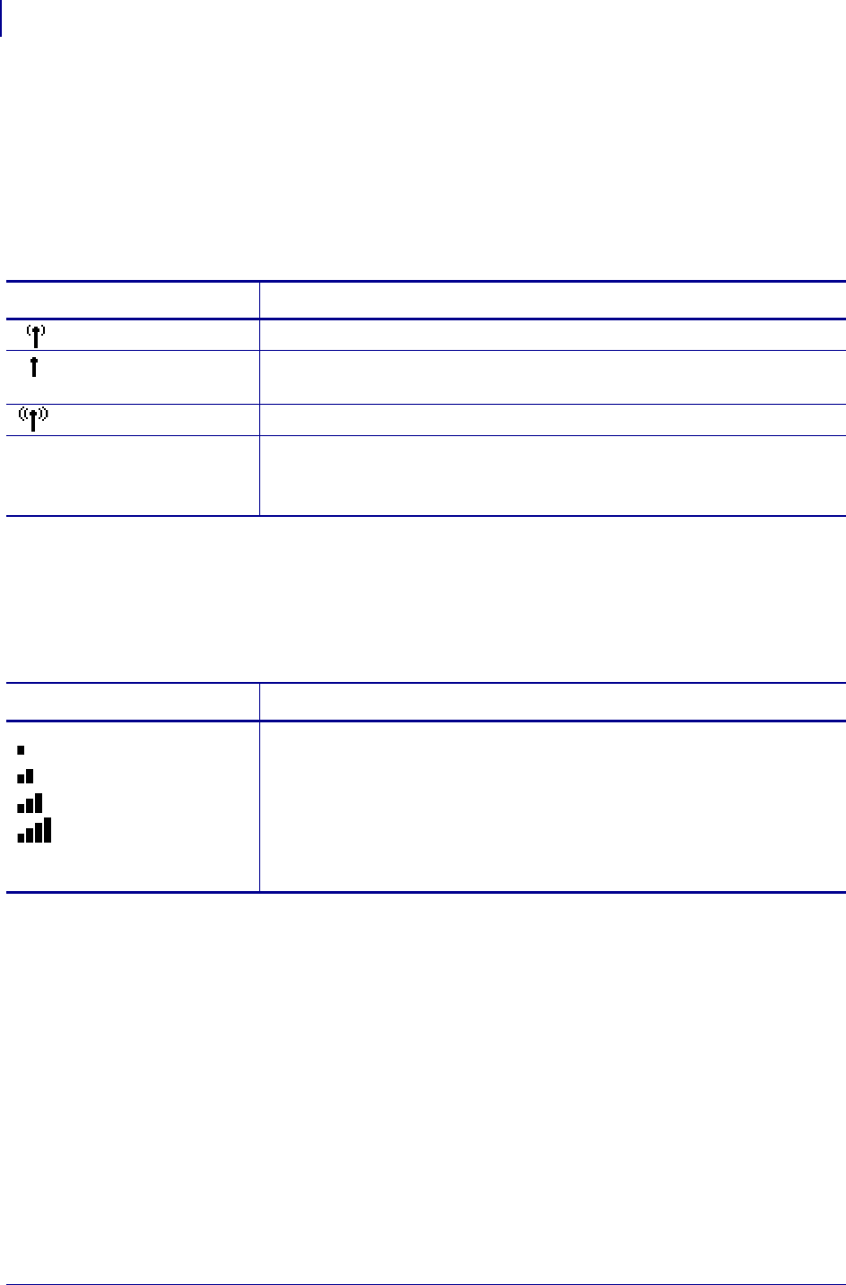
Setup
Configure Using the Connectivity Wizard
42
P1062653-002 Rev. A ZD500 Series™ Thermal Transfer Printer User’s Guide 1/16/2014
LCD Link Status and Wireless Signal Indicators
This section applies to printers and print engines other than the HC100 printer.
• Link Status Indicator (Table 5)
The wireless link status indicator appears at the upper right of the LCD, providing a
real-time display of the printer’s network status.
• Wireless Signal Indicators (Table 6)
The wireless signal indicators appears at the upper right of the LCD, providing a real-
time display of the signal strength and quality.
Table 5 • Link Status Indicators
Status Indicator Meaning
The wireless radio is associated with the WLAN.
The wireless radio is not associated with the WLAN. Verify that your
printer’s wireless settings match those of the WLAN.
The wireless radio is associated and authenticated to the WLAN.
blank •The printer is checking for a wired print server.
•The printer is running a wired print server.
•The wireless print server board is not installed or not installed correctly.
Table 6 • Wireless Signal Indicators
Wireless Signal Indicator Description
These bars indicate relative strength of the wireless signal. The more bars
shown, the better the connection is between the printer and the network.
If your printer indicates a signal strength but you cannot communicate with
the printer from your computer, move the printer to a different location to
try to get a better signal strength or signal quality. This situation could also
indicate that the printer is associated with, but not authenticated with, your
access point.
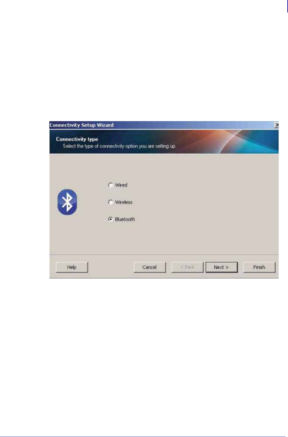
43
Setup
Bluetooth Option Configuration
1/16/2014 ZD500 Series™ Thermal Transfer Printer User’s Guide P1062653-002 Rev. A
Bluetooth Option Configuration
The Zebra Setup Utilities provides a quick and easy way to configure a Bluetooth wireless
connection with your printer.
1. Double-click the Zebra Setup Utilities icon on your desktop.
2. Connect a USB cable from your printer to your computer.
3. On the first ZSU screen, highlight the printer displayed in the window and click on the
Configure Printer Connectivity where shown.
4. Select “Bluetooth” on the Connectivity Type screen and click on the Next button.
5. On the Bluetooth Settings screen, check “Enabled” to enable Bluetooth functionality.
6. In the Friendly Name text field, set the Bluetooth name of the device. This name appears
during device discovery and the master device will label the printer with this name.
7. Set Discoverable to “On” or “Off” to set whether the device will appear when master
devices are looking for new devices to pair with.
8. Set Authentication to “On.” (Note: This setting does not exist in Link-OS, but you need to
turn on if you want to enter a PIN in ZSU. Actual authentication setting on the printer is
set in the Security Mode on the Advanced Settings menu.)
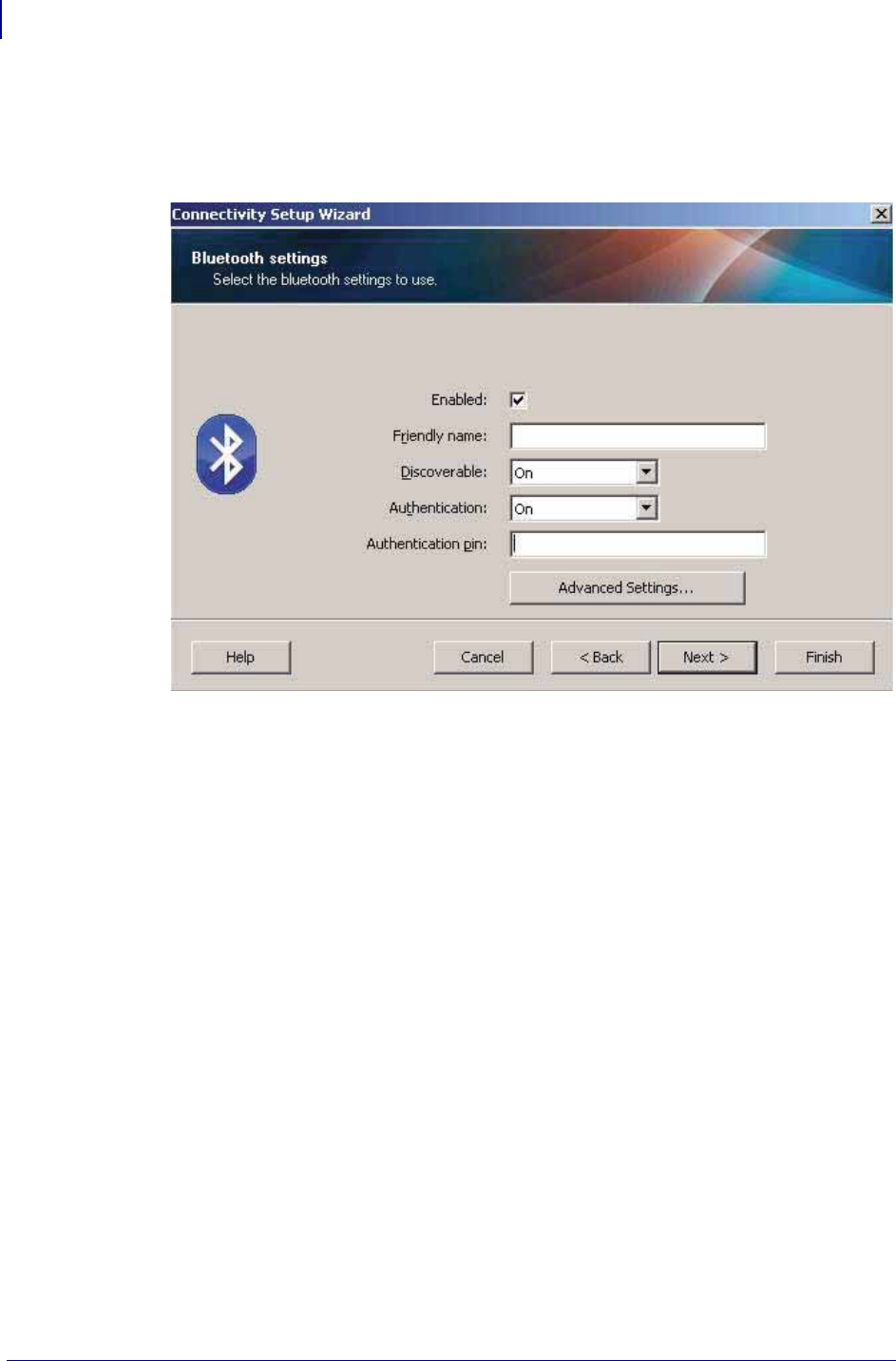
Setup
Bluetooth Option Configuration
44
P1062653-002 Rev. A ZD500 Series™ Thermal Transfer Printer User’s Guide 1/16/2014
9. The values set in the Authentication PIN field will vary depending on the Bluetooth
version of the master device. If the master uses BT v2.0 or older, enter a numeric value in
this field. You will be prompted to enter this same value on the master device to verify
pairing. Security Mode 2 or 3 in Advanced Settings should also be selected for PIN
paring.
10. If the master device uses BT v2.1 or newer, this setting has no effect. BT v2.1 and newer
uses Secure Simple Paring (SSP) which does not require the use of a PIN.
11. Clicking on the Advanced Settings button will display the Advanced Bluetooth Settings
window. For more information on Advanced Settings, refer to the Wired and Wireless
Print Server Guide.
12. Click Next to continue configuring your printer.
13. The SGD commands to properly configure your printer will be displayed. Click Next to
continue to the Send Data screen.
14. On the Send Data screen, you may click on the Printer that you want to immediately send
the commands to or you may click on the File button to save the commands to a file on
your computer that can be sent to one or more printers at a later time.
15. To send the commands to the printer, click on the Finish button and the printer will be
updated and then reboot. You may disconnect the USB interface from your printer now.
16. To complete the Bluetooth paring process, enable Bluetooth device discovery on your
master device and follow the directions provided with the master device.

45
Setup
Bluetooth Option Configuration
1/16/2014 ZD500 Series™ Thermal Transfer Printer User’s Guide P1062653-002 Rev. A
Connecting to a Windows XP® SP2 Master Device
This process covers the printer installation for Windows XP SP2 (or above)
1. From the Windows ‘Start’ menu, open the ‘Printers and Faxes’ window. Click on
‘Add Printer’ and a wizard will start. Click ‘Next’ when the “Welcome” window displays
to continue.
2. Leave the ‘Local’ radio button with the ‘Automatic detect ...’ checkbox (checked)
selected and click ‘Next’.
3. No printer should be found. If there is one or more new printers detected, then do not
select any of those printers and click ‘Next’.
4. Select the ‘Create a new port’ radio button and select ‘Bluetooth Printer Port’ from the
associated pull down menu.
5. From the new ‘Bluetooth Printer Port’ window, select your printer from the Bluetooth
devices in the list. This may take several minutes. Click on the ‘Connect’ button.
6. The ‘Install Printer Software’ window will open. Select ‘ZDesigner’ as ‘Manufacture’
to select supported Zebra printer models, and then select your printer model in the
‘Printers’ selection. Click ‘Next’ to continue.
7. Select ‘Keep the existing drivers’ and click ‘Next’.
8. Name your printer and choose your default printer setting as desired. Click ‘Next’.
9. Answer ‘Yes’, you want to print a test page. Click ‘Next’ to continue.
10. Click ‘Finish’ on the ‘Completing the Add Printer Wizard’ window and the Bluetooth
printer will complete installation and print a Windows test print page (a Windows logo at
minimum).
Connecting to a Windows Vista® SP2 or Windows 7® Master Device
The Windows Vista (SP2 or higher) and Windows 7 Bluetooth install differs from the XP
install.
•Windows Vista: Open the ‘Add Printer’ wizard by clicking the ‘Start’ button,
clicking ‘Control Panel’, clicking ‘Hardware and Sound’, clicking ‘Printers’,
and then clicking ‘Add a printer’.
•Windows 7: Open Devices and Printers by clicking the ‘Start’ button, and then,
on the ‘Start’ menu, clicking ‘Devices and Printers’
• Some non-Microsoft Bluetooth dongles and built-in Bluetooth devices in the host
PC’s have marginal driver support for Secure Simple Paring (SSP) printing and
may not complete the ‘Add printer’ wizard normally. You may need to go to the
‘Bluetooth Devices’ in the ‘Control Panel’ or from the system tray on the
Windows ‘Start’ bar and activate SPP for the ‘device’, your Bluetooth printer you
are installing. Install the printer to a local printer (USB or Serial Port for your
ZD500 Series™ printer) and then change the ‘Port’ after the install has completed
to the SPP (virtual serial port) COM port.
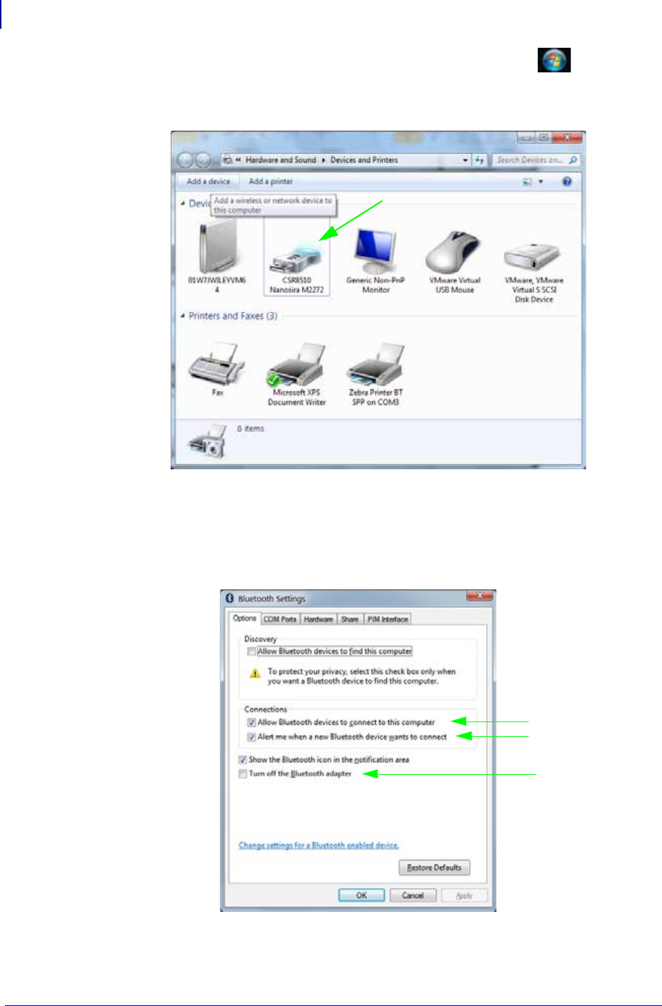
Setup
Bluetooth Option Configuration
46
P1062653-002 Rev. A ZD500 Series™ Thermal Transfer Printer User’s Guide 1/16/2014
1. Access the ‘Devices and Printers’ from the Windows Start menu ( ).
2. Check for Bluetooth devices in the ‘Devices and Printers’ window. Note the generic
Windows Bluetooth icon below.
3. Hover over the Bluetooth icon with the mouse pointer and the icon will highlight. Right-
Click on the high-lighted Bluetooth icon. Select ‘Bluetooth Settings’ from the pop-up
menu. Verify that both of the Connections check boxes are checked. Verify that the ‘Turn
off the Bluetooth adapter’ is not checked. Click the ‘Apply’ button. Click the ‘OK’
button to close the window.
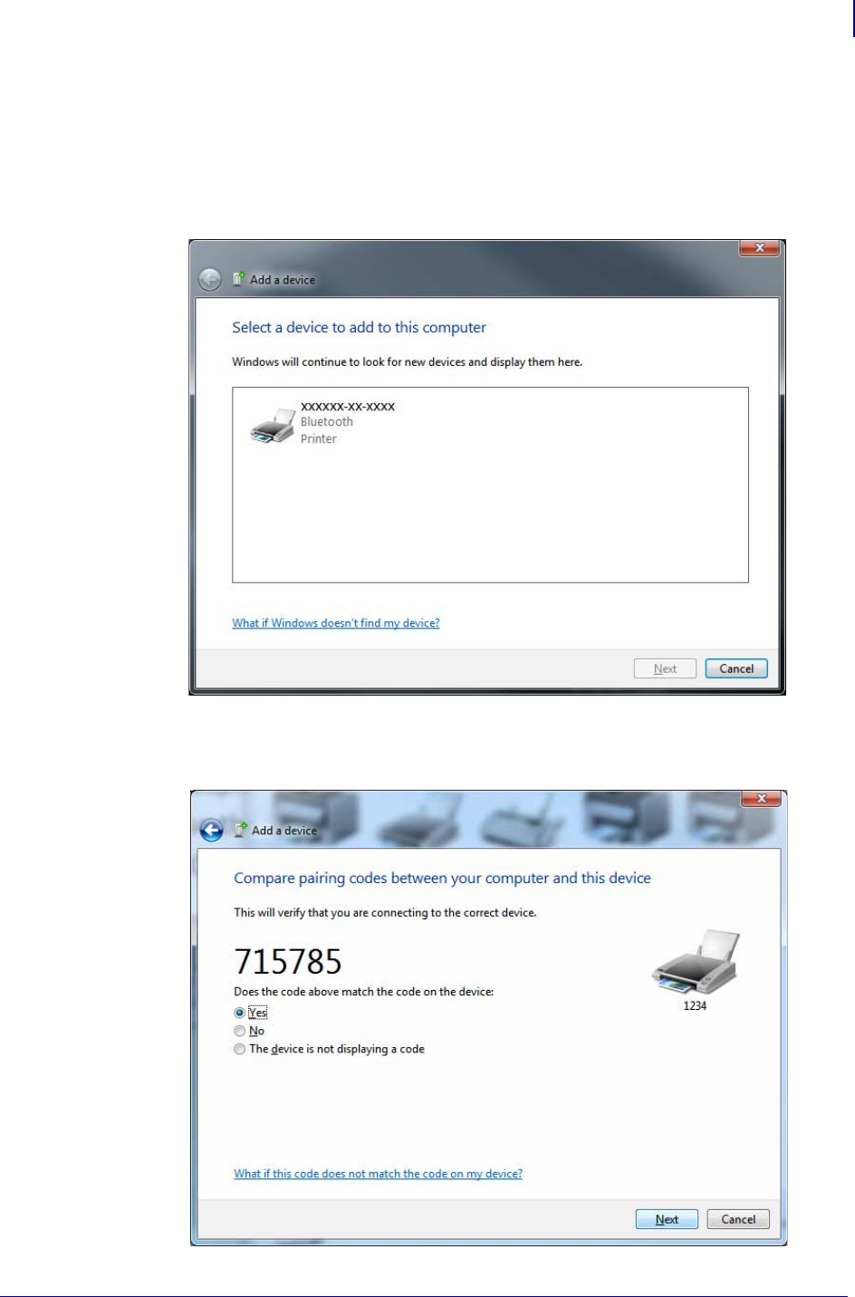
47
Setup
Bluetooth Option Configuration
1/16/2014 ZD500 Series™ Thermal Transfer Printer User’s Guide P1062653-002 Rev. A
4. Click on the ‘Add a device’ in the top bar of the “Devices and Printers’ window. After
a few moments the “Add a device’ windows will populate with Bluetooth devices near
you.
5. Turn the Bluetooth 3.0 enabled Zebra printer on. After a few moments the
“Add a device’ windows will add your new printer. Click on the printer icon. Right-Click
and select ‘Add device’.
6. The ‘Add a device’ window changes to a code pairing screen, see an example below. The
pairing code displayed is randomly generated by the Window operating system. Complete
the next two steps quickly
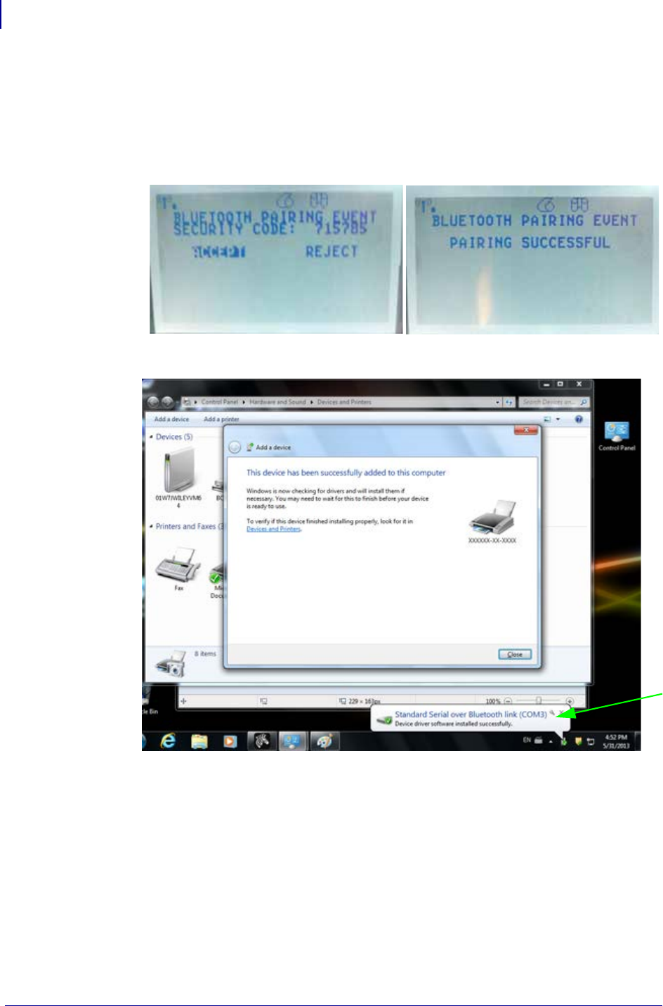
Setup
Bluetooth Option Configuration
48
P1062653-002 Rev. A ZD500 Series™ Thermal Transfer Printer User’s Guide 1/16/2014
7. Check the printer’s display for the following screen. Verify that the pairing numbers
match.
If the numbers match, then press the ‘Next button’ in the ‘Add a device’ window and
then press the OK/Check Mark button on the printer’s control panel.
If the numbers do not match, use the printer’s control panel arrow keys to change the
highlighted ACCEPT to REJECT and then press the OK/Check Mark button on the
printer’s control panel.
8. When the paring process successfully completes, the following message will be displayed.
Note • Note the COM port number displayed in the task bar pop-up. It will only remain for a
few seconds.

49
Setup
After Your Printer is Connected
1/16/2014 ZD500 Series™ Thermal Transfer Printer User’s Guide P1062653-002 Rev. A
After Your Printer is Connected
Now that you have basic communication to your printer, you may want to test printer
communications and then install other printer related applications, drivers or utilities.
Testing Communications by Printing
Verifying the print system’s operation is a relatively simple process. For Windows operating
systems, the Zebra Setup Utility or the Windows ‘Printers and Faxes’ Control Panel to access
and print a test label. For non-Windows operation systems, coping a basic ASCII text file with
a single command (~WC) to print a configuration status label.
Test Printing with Zebra Setup Utility:
1. Open the Zebra Setup Utility.
2. Click on the newly install printer’s icon to select the printer and active the printer
configuration buttons below it in the window.
3. Click the ‘Open Printer Tools’ button.
4. In the ‘Print’ tab window, click on the ‘Print configuration label’ line and click on the
‘Send’ button. The printer should print a configuration status label.
Test Printing with Windows ‘Printer and Faxes’ menu:
1. Click on the Windows ‘Start’ menu button, to access the ‘Printers and Faxes’ menu or
‘Control Panel’ to access the ‘Printers and Faxes’ menu. Open the menu.
2. Select the newly install printer’s icon to select the printer and right-click the mouse to
access the printer ‘Properties’ menu.
3. From the printer’s ‘General’ tab window, click on the ‘Print Test Page’ button. The
printer should print a Windows test print page.
Test Print on a Ethernet printer connected to a network (LAN or WAN) with a
(MS-DOS) ‘Command Prompt’ (or ‘Run’ from the Windows XP Start menu):
1. Create a text file with the following ASCII three characters: ~WC
2. Save the file as: TEST.ZPL (an arbitrary file name and extension name).
3. Read the IP address off the printer’s Configuration Status Label’s Network Status printout.
On a system that is connected to the same LAN or WAN as the printer, type the following
in the Web browser window’s address bar and enter:
ftp (IP address)
(for IP address 123.45.67.01 it would be: ftp 123.45.67.01)
4. Type the word ‘put’ followed by the file name and enter. For this ‘test print’ file, it would
be: put TEST.ZPL
The printer should print a new Print Configuration Status label.

Setup
After Your Printer is Connected
50
P1062653-002 Rev. A ZD500 Series™ Thermal Transfer Printer User’s Guide 1/16/2014
Test Print with a Copied ZPL Command File for Non-Windows Operating Systems:
1. Create a text file with the following ASCII three characters: ~WC
2. Save the file as: TEST.ZPL (an arbitrary file name and extension name).
3. Copy the file to the printer. For DOS, a file sent to a printer connected to the system’s
parallel port would be as simple as:
COPY TEST.ZPL LPT1
Other interface connection types and operating systems will have different command
strings. See your operating system documentation for detailed instructions to copy to the
appropriate printer interface for this test.

1/16/2014 ZD500 Series™ Thermal Transfer Printer User’s Guide P1062653-002 Rev. A
3
Printer Configuration
Changing Printer Settings
This section presents the printer settings that you can change and identifies the tools for
changing them. These tools include the following:
• The control panel menu
• ZPL and Set/Get/Do (SGD) commands (See the Zebra® Programming Guide for
more information.)
• The printer’s web pages when the printer has an active wired or wireless print server
connection (See the ZebraNet Wired and Wireless Print Servers User Guide for more
information.)
Copies of the referenced manuals are available at http://www.zebra.com/manuals or on the
user CD that came with your printer.
This section contains the following subsections:
•SETTINGS Menu on page 52
•TOOLS Menu on page 56
•NETWORK Menu on page 61
•RFID Menu on page 65
•LANGUAGE Menu on page 69
•SENSOR Menu on page 71
•PORTS Menu on page 72
•BLUETOOTH Menu on page 74
•Manual Calibration - Media on page 75
•RFID Calibration on page 76

Printer Configuration
Changing Printer Settings
52
P1062653-002 Rev. A ZD500 Series™ Thermal Transfer Printer User’s Guide 1/16/2014
SETTINGS Menu
Table 7 • SETTINGS Menu
Print
Darkness
Set the darkness to the lowest setting that provides good print quality. If you set the darkness
too high, the label image may print unclearly, bar codes may not scan correctly, the ribbon
may burn through, or the printhead may wear prematurely.
If desired, use the Print Quality Report on page 135 to determine the best darkness setting.
Accepted values: 0.0 – 30.0
Related ZPL command(s): ^MD, ~SD
SGD command used: print.tone
Printer web page: View and Modify Printer Settings > General Setup >
Darkness
Print Speed Select the speed for printing a label (given in inches per second). Slower print speeds
typically yield better print quality.
Accepted values: 2, 3, 4, 5, 6
Related ZPL command(s): ^PR
SGD command used: media.speed
Printer web page: N/A
Media Type Select the type of media that you are using.
•If you select CONTINUOUS, you must include a label length in your label format (^LL
if you are using ZPL).
•If you select GAP/NOTCH or MARK for various non-continuous media, the printer
feeds media to calculate the label length.
See Types of Media on page 79 for more information.
Accepted values: •CONTINUOUS
•GAP/NOTCH
•MARK
Related ZPL command(s): ^MN
SGD command used: ezpl.media_type
Printer web page: View and Modify Printer Settings > Media Setup >
Media Type
Print Method Specify if the printer is to use Direct Thermal mode (no ribbon) or Thermal Transfer mode
(using thermal transfer media and ribbon).
Accepted values: •THERMAL TRANS
•DIRECT THERMAL
Related ZPL command(s): ^MT
SGD command used: ezpl.print_method
Printer web page: View and Modify Printer Settings > Media Setup >
Print Method
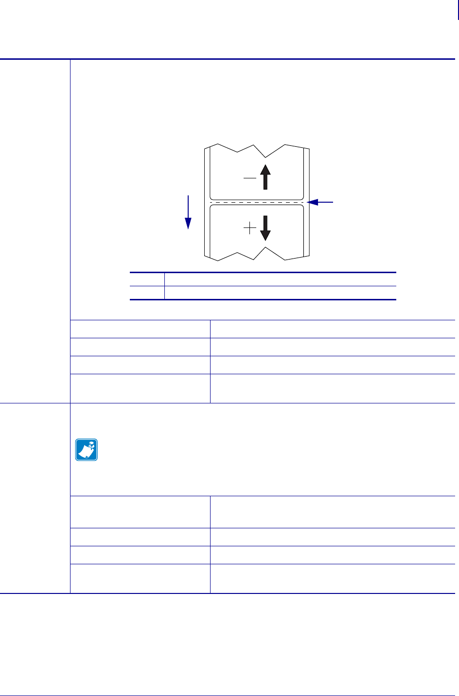
53
Printer Configuration
Changing Printer Settings
1/16/2014 ZD500 Series™ Thermal Transfer Printer User’s Guide P1062653-002 Rev. A
Tear-Off
Position
If necessary, adjust the position of the media extending out of the printer after printing.
•Higher numbers move the media out (the tear line moves closer to the leading edge of
the next label).
•Lower numbers move the media in (the tear line moves closer to the edge of the label
just printed).
•Note - Tear-Off does not affect RFID program position.
Accepted values: –120 to 120
Related ZPL command(s): ~TA
SGD command used: ezpl.tear_off
Printer web page: View and Modify Printer Settings > General Setup >
Te a r Of f
Print Width Specify the width of the labels being used. The default value is the maximum width for the
printer, based on the printhead’s DPI value.
Note • Setting the width too narrow can result in portions of a label format not being
printed on the media. Setting the width too wide wastes formatting memory and can
cause the printer to print off of the label and onto the platen roller. This setting can
affect the horizontal position of the label format if the image was inverted using the
^POI ZPL II command.
Accepted values: 0000 to 0832 dots (200 dpi printers)
0000 to 1280 dots (300 dpi printers)
Related ZPL command(s): ^PW
SGD command used: ezpl.print_width
Printer web page: View and Modify Printer Settings > Media Setup >
Print Width
Table 7 • SETTINGS Menu (Continued)
1
2
1Media direction
2Factory-set tear line location at position 000

Printer Configuration
Changing Printer Settings
54
P1062653-002 Rev. A ZD500 Series™ Thermal Transfer Printer User’s Guide 1/16/2014
Print Mode Select a print mode that is compatible with your printer options.
Accepted values: •TEAR OFF
•PEEL OFF (use this value for Label Dispensing:
Separates the liner from the label and presents a
peeled label to the operator)
•REWIND
•CUTTER
•DELAYED CUT
•LINERLESS PEEL
•LINERLESS REWIND
•LINERLESS TEAR
Related ZPL command(s): ^MM
SGD command used: media.printmode
Printer web page: View and Modify Printer Settings > General Setup >
Print Mode
Label Top If necessary, shift the print position vertically on the label. A negative value moves the
format towards the top of the label; a positive value moves the format away from the top of
the label.
Accepted values: –120 to 120
Related ZPL command(s): ^LT
SGD command used: zpl.label_top
Printer web page: View and Modify Printer Settings > Advanced Setup
> Top Position
Label Left
Position
If necessary, shift the print position horizontally on the label. Positive numbers move the left
edge of the image toward the center of the label by the number of dots selected, while
negative numbers move the left edge of the image toward the left edge of the label.
Accepted values: –9999 to 9999
Related ZPL command(s): ^LS
SGD command used: zpl.left_position
Printer web page: View and Modify Printer Settings > Advanced Setup
> Left Position
Reprint
Mode
When reprint mode is enabled, you can reprint the last label printed by pressing and holding
PAUSE + CANCEL on the printer’s control panel.
Accepted values: •ON
•OFF
Related ZPL command(s): ^JZ
SGD command used: ezpl.reprint_mode
Printer web page: N/A
Table 7 • SETTINGS Menu (Continued)
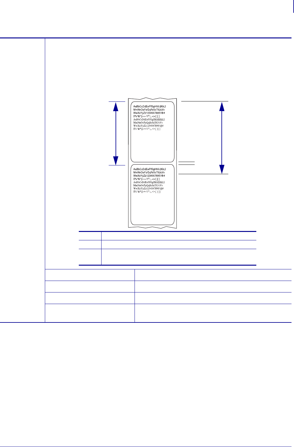
55
Printer Configuration
Changing Printer Settings
1/16/2014 ZD500 Series™ Thermal Transfer Printer User’s Guide P1062653-002 Rev. A
Maximum
Label Length
Set the maximum label length to a value that is at least 1.0 in. (25.4 mm) greater than the
actual label length plus the interlabel gap. If you set the value to one that is smaller than the
label length, the printer assumes that continuous media is loaded, and the printer cannot
calibrate.
For example, if the label length is 6.0 inches (152 mm) including the inter-label gap, set the
parameter for at least 7.0 inches (178 mm).
Accepted values: 0 to the maximum label length supported by the printer
Related ZPL command(s): ^ML
SGD command used: ezpl.label_length_max
Printer web page: View and Modify Printer Settings > Media Setup >
Maximum Length
Table 7 • SETTINGS Menu (Continued)
2
1Label length (including interlabel gap)
2Interlabel gap
3Set the maximum label length to approximately
this value
13

Printer Configuration
Changing Printer Settings
56
P1062653-002 Rev. A ZD500 Series™ Thermal Transfer Printer User’s Guide 1/16/2014
TOOLS Menu
Table 8 • TOOLS MENU
Print
Information
Prints the specified information on the media, if non-continuous media the information
will be displayed on one or more labels (tags, tickets, etc.).
Accepted values: •SETTINGS—prints the printer configuration
report.
•NETWORK—prints the settings for any print
server that is installed.
•FORMATS—prints the available formats stored
in the printer’s RAM, Flash memory, or optional
memory card.
•IMAGES—prints the available images stored in
the printer’s RAM, Flash memory, or optional
memory card.
•FONTS—prints the available fonts in the printer,
including standard printer fonts plus any optional
fonts. Fonts may be stored in RAM or Flash
memory.
•BARCODES—prints the available bar codes in
the printer. Bar codes may be stored in RAM or
Flash memory.
•ALL—prints the previous six labels.
•SENSOR PROFILE—shows the sensor settings
compared to actual sensor readings. To interpret
the results of the sensor profile, see Sensor Profile
on page 140.
Related ZPL command(s): Settings: ~WC
Network: ~WL
Sensor profile: ~JG
Others: ^WD
SGD command used: none
Control panel key(s): Settings and Network: Do one of the following:
•Hold CANCEL during printer power-up.
•Hold FEED + CANCEL for 2 seconds when
the printer is in the Ready state.
Sensor profile: Hold FEED + CANCEL during
printer power-up.
Printer web page: View and Modify Printer Settings >
Print Listings on Label

57
Printer Configuration
Changing Printer Settings
1/16/2014 ZD500 Series™ Thermal Transfer Printer User’s Guide P1062653-002 Rev. A
LCD Contrast Change the contrast on the printer’s display.
Accepted values: 3 to 15
Related ZPL command(s): none
SGD command used: display.contrast
Printer web page: N/A
Idle Display Select the information shown on the printer’s display when the printer is idle.
Accepted values: •FW VERSION
•IP ADDRESS
•MM/DD/YY 24 HR
•M/DD/YY 12 HR
•DD/MM/YY 24 HR
•DD/MM/YY 12 HR
Related ZPL command(s): none
SGD command used: device.idle_display_format
Printer web page: N/A
Power-Up Action Set the Power-Up Action
Set the action for the printer to take during the power-up sequence.
•CALIBRATE adjusts sensor levels and thresholds, determines the label length, and
feeds the media to the next web.
•FEED—feeds the labels to the first registration point.
•LENGTH determines the label length using current sensor values, and feeds the
media to the next web.
•NO MOTION tells the printer not to move the media. You must manually ensure
that the web is positioned correctly, or press feed to position the next web.
•SHORT CAL sets the media and web thresholds without adjusting sensor gain,
determines the label length, and feeds the media to the next web.
Accepted values: •CALIBRATE
•FEED
•LENGTH
•NO MOTION
•SHORT CAL
Related ZPL command(s): ^MF
SGD command used: ezpl.power_up_action
Printer web page: View and Modify Printer Settings > Calibration
Table 8 • TOOLS MENU (Continued)

Printer Configuration
Changing Printer Settings
58
P1062653-002 Rev. A ZD500 Series™ Thermal Transfer Printer User’s Guide 1/16/2014
Head-Close
Action
Set the Head-Close Action
Set the action for the printer to take when you close the printhead.
•CALIBRATE adjusts sensor levels and thresholds, determines the label length, and
feeds the media to the next web.
•FEED—feeds the labels to the first registration point.
•LENGTH determines the label length using current sensor values, and feeds the
media to the next web.
•NO MOTION tells the printer not to move the media. You must manually ensure
that the web is positioned correctly, or press feed to position the next web.
•SHORT CAL sets the media and web thresholds without adjusting sensor gain,
determines the label length, and feeds the media to the next web.
Accepted values: •CALIBRATE
•FEED
•LENGTH
•NO MOTION
•SHORT CAL
Related ZPL command(s): ^MF
SGD command used: ezpl.head_close_action
Printer web page: View and Modify Printer Settings > Calibration
Table 8 • TOOLS MENU (Continued)

59
Printer Configuration
Changing Printer Settings
1/16/2014 ZD500 Series™ Thermal Transfer Printer User’s Guide P1062653-002 Rev. A
Load Defaults Load Printer or Print Server Defaults
•FACTORY—Restores all printer settings other than the network settings back to the
factory defaults. Use care when loading defaults because you will need to reload all
settings that you changed manually.
•NETWORK—Reinitializes the printer’s wired or wireless print server. With a
wireless print server, the printer will also reassociate with your wireless network.
•LAST SAVED—Loads settings from the last permanent save.
Accepted values: •FACTORY
•NETWORK
•LAST SAVED
Related ZPL command(s): Factory: ^JUF
Network: ^JUN
Last saved: ^JUR
SGD command used: none
Control panel key(s): Factory: Hold FEED + PAUSE during printer
power-up to reset the printer parameters to factory
values.
Network: Hold CANCEL + PAUSE during printer
power-up to reset the network parameters to factory
values.
Last saved: N/A
Printer web page: Factory: View and Modify Printer Settings >
Restore Default Configuration
Network: Print Server Settings > Reset Print
Server
Last saved: View and Modify Printer Settings >
Restore Saved Configuration
Manual
Calibration
Calibrate the printer to adjust the sensitivity of the media and ribbon sensors.
For complete instructions on how to perform a calibration procedure, see Manual
Calibration - Media on page 75.
Accepted values: N/A
Related ZPL command(s): ~JC
SGD command used: ezpl.manual_calibration
Control panel key(s): Hold PAUSE + FEED + CANCEL for 2 seconds to
initiate calibration.
Printer web page: The calibration procedure cannot be initiated through
the web pages. See the following web page for
settings that are set during sensor calibration:
View and Modify Printer Settings > Calibration
Important • Do not change these settings
unless you are told to do so by Zebra
Technical Support or by an authorized service
technician.
Table 8 • TOOLS MENU (Continued)

Printer Configuration
Changing Printer Settings
60
P1062653-002 Rev. A ZD500 Series™ Thermal Transfer Printer User’s Guide 1/16/2014
Communication
Diagnostics Mode
Use this diagnostics tool to cause the printer to output the hexadecimal values for all
data received by the printer.
For more information, see Communication Diagnostics Test on page 139.
Accepted values: •DISABLED
•ENABLED
Related ZPL command(s): ~JD to enable, ~JE to disable
SGD command used: device.diagnostic_print
Control panel key(s): Hold PAUSE + FEED for 2 seconds when the
printer is in the Ready state.
Printer web page: N/A
Enable ZBI Zebra Basic Interpreter (ZBI 2.0™) is a programming option that may be purchased for
your printer. If you would like to purchase this option, contact your Zebra reseller for
more information.
Accepted values: N/A
Related ZPL command(s): none
SGD command used: zbi.key (identifies if the ZBI 2.0 option is enabled
or disabled on the printer)
Printer web page: N/A
Run a ZBI
Program
If you have ZBI installed, you may choose to run a ZBI program that you have
downloaded to your printer.
Accepted values: N/A
Related ZPL command(s): ^JI, ~JI
SGD command used: zbi.control.run
Printer web page: Directory Listing
Stop a ZBI
Program
If your printer is running a ZBI program, you may stop that program.
Accepted values: N/A
Related ZPL command(s): ~JQ
SGD command used: zbi.control.terminate
Printer web page: Directory Listing
Table 8 • TOOLS MENU (Continued)

61
Printer Configuration
Changing Printer Settings
1/16/2014 ZD500 Series™ Thermal Transfer Printer User’s Guide P1062653-002 Rev. A
NETWORK Menu
Table 9 • NETWORK Menu
WIRED or
WLAN
IP Address
View or Set the Printer’s IP Address
View and, if necessary, change the printer’s IP address.
Changes to this setting are saved only if IP PROTOCOL is set to PERMANENT. To
allow any saved changes to take effect, reset the print server (see RESET NETWORK
in this section).
Accepted values: 000 to 255 for each field
Related ZPL command(s): ^ND
SGD command used: Wired: internal_wired.ip.addr
Wireless: ip.addr, wlan.ip.addr
Printer web page: View and Modify Printer Settings >
Network Communications Setup >
TCP/IP Settings
WIRED or
WLAN
Subnet Mask
View or Set the Subnet Mask
View and, if necessary, change the subnet mask.
This menu item appears only if a wired or wireless print server is installed on your
printer. To save changes to this setting, set IP PROTOCOL to PERMANENT, and then
reset the print server (see RESET NETWORK in this section).
Accepted values: 000 to 255 for each field
Related ZPL command(s): ^ND
SGD command used: Wired: internal_wired.ip.netmask
Wireless: wlan.ip.netmask
Printer web page: View and Modify Printer Settings >
Network Communications Setup >
TCP/IP Settings
WIRED or
WLAN
Gateway
View or Set the Default Gateway
View and, if necessary, change the default gateway.
This menu item appears only if a wired or wireless print server is installed on your
printer. To save changes to this setting, set IP PROTOCOL to PERMANENT, and then
reset the print server (see RESET NETWORK in this section).
Accepted values: 000 to 255 for each field
Related ZPL command(s): ^ND
SGD command used: Wired: internal_wired.ip.gateway
Wireless: wlan.ip.gateway
Printer web page: View and Modify Printer Settings >
Network Communications Setup >
TCP/IP Settings

Printer Configuration
Changing Printer Settings
62
P1062653-002 Rev. A ZD500 Series™ Thermal Transfer Printer User’s Guide 1/16/2014
WIRED or
WLAN
IP Protocol
Set the IP Resolution Method
This parameter tells if the user (permanent) or the server (dynamic) selects the
IP address. If a dynamic option is chosen, this parameter tells the method(s) by which
the wired or wireless print server receives the IP address from the server.
Accepted values: •ALL
•GLEANING ONLY
•RARP
•BOOTP
•DHCP
•DHCP & BOOTP
•PERMANENT
Related ZPL command(s): ^ND
SGD command used: Wired: internal_wired.ip.protocol
Wireless: wlan.ip.protocol
Printer web page: View and Modify Printer Settings >
Network Communications Setup >
TCP/IP Settings
WIRED or
WLAN
MAC Address
View the MAC Address
View the Media Access Control (MAC) address of the print server that is installed in the
printer (wired or wireless).
Accepted values: N/A
Related ZPL command(s): none
SGD command used: Wired: internal_wired.mac_addr
Wireless: wlan.mac_addr
Printer web page: View and Modify Printer Settings >
Network Communications Setup >
Wireless Setup
ESSID View the ESSID Value
The Extended Service Set Identification (ESSID) is an identifier for your wireless
network. This setting, which cannot be modified from the control panel, gives the
ESSID for the current wireless configuration.
Accepted values: 32-character alphanumeric string (default 125)
Related ZPL command(s): none
SGD command used: wlan.essid
Printer web page: View and Modify Printer Settings >
Network Communications Setup >
Wireless Setup
Table 9 • NETWORK Menu (Continued)

63
Printer Configuration
Changing Printer Settings
1/16/2014 ZD500 Series™ Thermal Transfer Printer User’s Guide P1062653-002 Rev. A
Channel View the Channel Value
This parameter retrieves the current WI-FI channel the printer is using.
Accepted values: N/A
Related ZPL command(s): none
SGD command used: wlan.essid
Printer web page: View and Modify Printer Settings >
Network Communications Setup >
Wireless Setup
Signal View the Signal Value
This parameter returns the signal strength of the connection to the access point
as a percentage value between zero (not connected) and 100 (strongest signal). Values
below 40% represent a very poor signal and radio communication is not reliable.
Accepted values: N/A
Related ZPL command(s): none
SGD command used: wlan.signal_strength
Printer web page: View and Modify Printer Settings >
Network Communications Setup >
Wireless Setup
IP Port View the IP Port Value
This printer setting refers to the wireless print server’s port number that the TCP print
service is listening on. Normal TCP communications from the host should be
directed to this port.
Accepted values: N/A
Related ZPL command(s): none
SGD command used: wlan.ip.port
Printer web page: View and Modify Printer Settings >
Network Communications Setup >
Wireless Setup
IP Alternate Port View the IP Alternate Port Value
This command sets the port number of the alternate WLAN port.
Note - Print servers supporting this command will monitor both the primary port and
the alternate port for connections at the same time.
Accepted values: 32-character alphanumeric string (default 125)
Related ZPL command(s): none
SGD command used: wlan.ip.port_alternate
Printer web page: View and Modify Printer Settings >
Network Communications Setup >
Wireless Setup
Table 9 • NETWORK Menu (Continued)

Printer Configuration
Changing Printer Settings
64
P1062653-002 Rev. A ZD500 Series™ Thermal Transfer Printer User’s Guide 1/16/2014
Reset Network This option resets the wired or wireless print server. You must reset the print server to
allow any changes to the network settings to take effect.
Accepted values: N/A
Related ZPL command(s): ~WR
SGD command used: device.reset
Printer web page: Print Server Settings >
Factory Print Server Settings
Table 9 • NETWORK Menu (Continued)

65
Printer Configuration
Changing Printer Settings
1/16/2014 ZD500 Series™ Thermal Transfer Printer User’s Guide P1062653-002 Rev. A
RFID Menu
See the latest version of the RFID Programming Guide 3 for more information on using this
printer’s RFID module. Go to the Zebra Web site: www.zebra.com
Table 10 • RFID Menu
RFID Status Display the status of the RFID subsystem of the printer.
Accepted values: N/A
Related ZPL command(s): ^HL or ~HL
SGD command used: rfid.error.response
Printer web page: N/A
RFID Calibrate Use this command to initiate tag calibration for RFID media. (Not the same as manual
calibration for media.) During the process, the printer moves the media, calibrates the
RFID tag position, and determines the optimal settings for the RFID media being used.
Important • Before you use this command, load the printer with RFID media, ensure
that the printer is calibrated for the media, and close the printhead. Feed one label.
See Manual Calibration - Media on page 75 to calibrate the media (and RFID
Calibration on page 76 for a menu accessible alternative method to this command).
Depending on the printer, these settings include the programming position, the antenna
element to use, the read/write power level to use, and it read's the tag's TID to determine
the chip type.
To restore the printer’s default programming position at any time, use the "restore"
option in the rfid.tag.calibrate SGD command.
Leave all transponders before and after the tag that is being calibrated. This allows the
printer to determine RFID settings which do not encode the adjacent tag. Allow a
portion of media to extend out the front of the printer to allow for backfeed during the
tag calibration procedure.
Accepted values: N/A
Related ZPL command(s): ^HR
SGD command used: rfid.tag.calibrate
Printer web page: N/A

Printer Configuration
Changing Printer Settings
66
P1062653-002 Rev. A ZD500 Series™ Thermal Transfer Printer User’s Guide 1/16/2014
Read RFID Data Read and return the specified tag data from the RFID tag located over the RFID
antenna. No printer movement occurs while tag data is being read. The printhead can be
open or closed.
Accepted values: EPC = reads the first 128 bits of EPC data
memory bank sizes = reads the EPC, TID, and
USER memory banks sizes. Determines the
sizes of the EPC, TID, and USER memory
banks.
protocol bits = reads the protocol bits from the EPC
memory banks and converts that value to the
EPC size
TID information = reads the first 32 bits of the TID
(Tag ID)
password status = reads the tag’s access and kill
passwords
Related ZPL command(s): ^RF
SGD command used: rfid.tag.read.content
and
rfid.tag.read.execute
Printer web page: N/A
RFID Test During the RFID test, the printer attempts to read and write to a transponder. No printer
movement occurs with this test.
Note - Ensure that the RFID tag is positioned over the printer's RFID antenna.
Accepted values: quick = performs a read EPC test and a write EPC
test (using random data)
read = performs a read EPC test
write = performs a write EPC test (using random
data)
Related ZPL command(s): N/A
SGD command used: rfid.tag.test.content
and
rfid.tag.test.execute
Printer web page: N/A
Table 10 • RFID Menu (Continued)

67
Printer Configuration
Changing Printer Settings
1/16/2014 ZD500 Series™ Thermal Transfer Printer User’s Guide P1062653-002 Rev. A
Programming
Position
If the desired programming position (read/write position) is not achieved through RFID
tag calibration, a value may be specified. See the Zebra RFID Programming Guide 3 for
more details.
Accepted values: F0 to Fxxx (where xxx is the label length in
millimeters or 999, whichever is less)
The printer feeds the label forward for the
specified distance and then begins
programming.
B0 to B30
The printer backfeeds the label for the
specified distance and then begins
programming. To account for the backfeed,
allow empty media liner to extend out of the
front of the printer when using a backward
programming position.
Related ZPL command(s): ^RS
SGD command used: rfid.position.program
Printer web page: View and Modify Printer Settings > RFID Setup
> PROGRAM POSITION
RFID Read
Power
If the desired read power is not achieved through RFID tag calibration, a value may be
specified.
Accepted values: 0 to 30
Related ZPL command(s): ^RW
SGD command used: rfid.reader_1.power.read
Printer web page: View and Modify Printer Settings > RFID Setup
> RFID READ PWR
RFID Write
Power
If the desired write power is not achieved through RFID tag calibration, a value may be
specified.
Accepted values: 0 to 30
Related ZPL command(s): ^RW
SGD command used: rfid.reader_1.power.write
Printer web page: View and Modify Printer Settings > RFID Setup
> RFID WRITE PWR
RFID Valid
Counter
Resets the RFID valid label counter to zero.
Accepted values: N/A
Related ZPL command(s): ~RO
SGD command used: odometer.rfid.valid_resettable
Printer web page: N/A
Table 10 • RFID Menu (Continued)

Printer Configuration
Changing Printer Settings
68
P1062653-002 Rev. A ZD500 Series™ Thermal Transfer Printer User’s Guide 1/16/2014
RFID Void
Counter
Resets the RFID void label counter to zero.
Accepted values: N/A
Related ZPL command(s): ~RO
SGD command used: odometer.rfid.void_resettable
Printer web page: N/A
RFID Tag
Calibration
Initiate tag calibration for RFID media. (Not the same as manual calibration for media.)
Accepted values: N/A
Related ZPL command(s): ^HR
SGD command used: rfid.tag.calibrate
Printer web page: N/A
Table 10 • RFID Menu (Continued)

69
Printer Configuration
Changing Printer Settings
1/16/2014 ZD500 Series™ Thermal Transfer Printer User’s Guide P1062653-002 Rev. A
LANGUAGE Menu
Table 11 • LANGUAGE Menu
Language If necessary, change the language that the printer displays.
This change affects the words shown on the following:
•the Home menu
•the user menus
•error messages
•the printer configuration label, the network configuration label, and other labels that you
can select to print through the user menus.
Note • The selections for this parameter are displayed in the actual languages to
make it easier for you to find one that you are able to read.
Accepted values: See the ZPL programmer’s guide - ZPL and SGD enter
the values differently.
Related ZPL command(s): ^KL
SGD command used: display.language
Printer web page: View and Modify Printer Settings > General Setup >
Language
ZPL
Override
Enable ZPL Override
Enable this menu item to prevent the following ZPL commands from changing the printer’s
current settings:
•^MM (print mode)
•^MT (Direct Thermal or Thermal Transfer print method)
•^MN (media type non-continuous or continuous)
When this menu item is disabled, these commands override the printer’s settings.
Accepted values: •DISABLED
•ENABLED
Related ZPL command(s): none
SGD command used: zpl.zpl_override
Printer web page: N/A

Printer Configuration
Changing Printer Settings
70
P1062653-002 Rev. A ZD500 Series™ Thermal Transfer Printer User’s Guide 1/16/2014
Command
Character
Set the Format Command Prefix Value
The format command prefix is a two-digit hex value used as a parameter place marker in
ZPL/ZPL II format instructions. The printer looks for this hex character to indicate the start
of a ZPL/ZPL II format instruction.
Set the format command character to match what is used in your label formats.
Important • You cannot use the same hex value for the format command prefix,
control character, and delimiter characters. The printer must see different characters
to work properly. If you are setting the value through the control panel, the printer
will skip any value that is already in use.
Accepted values: 00 to FF
Related ZPL command(s): ^CC or ~CC
SGD command used: zpl.caret
Printer web page: View and Modify Printer Settings > ZPL Control
Control
Character
Set the Control Prefix Character Value
The printer looks for this two-digit hex character to indicate the start of a ZPL/ZPL II
control instruction.
Set the control prefix character to match what is used in your label formats.
Accepted values: 00 to FF
Related ZPL command(s): ^CT or ~CT
SGD command used: zpl.control_character
Printer web page: View and Modify Printer Settings > ZPL Control
Delimiter
Character
Set the Delimiter Character Value
The delimiter character is a two-digit hex value used as a parameter place marker in
ZPL/ZPL II format instructions.
Set the delimiter character to match what is used in your label formats.
Accepted values: 00 to FF
Related ZPL command(s): ^CD or ~CD
SGD command used: zpl.delimiter
Printer web page: View and Modify Printer Settings > ZPL Control
ZPL Mode Set the ZPL Mode
Select the mode that matches what is used in your label formats.
This printer accepts label formats written in either ZPL or ZPL II, eliminating the need to
rewrite any ZPL formats that already exist. The printer remains in the selected mode until it
is changed in one of the ways listed here.
Accepted values: •ZPL II
•ZPL
Related ZPL command(s): ^SZ
SGD command used: zpl.zpl_mode
Printer web page: View and Modify Printer Settings > ZPL Control
Table 11 • LANGUAGE Menu (Continued)
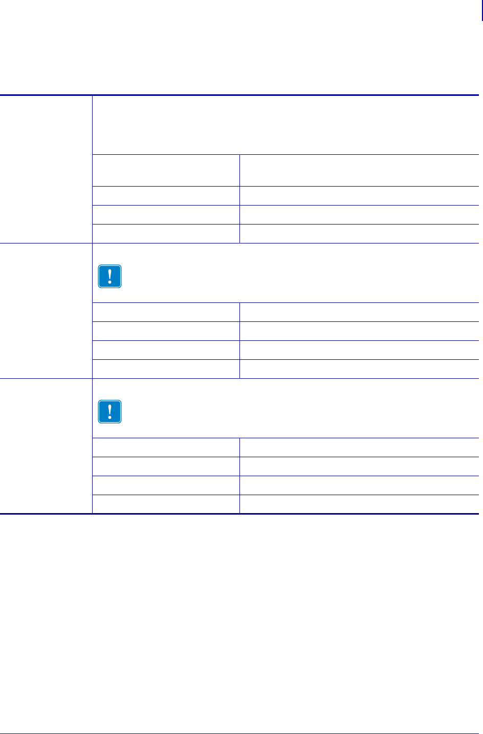
71
Printer Configuration
Changing Printer Settings
1/16/2014 ZD500 Series™ Thermal Transfer Printer User’s Guide P1062653-002 Rev. A
SENSOR Menu
Table 12 • SENSOR Menu
Sensor Type Select the Media Sensor
Select the media sensor that is appropriate for the media that you are using. The
reflective sensor can be used with all media types. The transmissive sensor should be
used only for simple gap media.
Accepted values: •TRANSMISSIVE
•REFLECTIVE
Related ZPL command(s): ^JS
SGD command used: device.sensor_select
Printer web page: View and Modify Printer Settings > Media Setup
Label Sensor Set the Sensitivity of the Label Sensor
Important • This value is set during sensor calibration. Do not change this
setting unless you are told to do so by Zebra Technical Support or by an
authorized service technician.
Accepted values: 0 – 255
Related ZPL command(s): none
SGD command used: ezpl.label_sensor
Printer web page: View and Modify Printer Settings > Calibration
Take Label Set the Intensity of the Take Label LED
Important • This value is set during sensor calibration. Do not change this
setting unless you are told to do so by Zebra Technical Support or by an
authorized service technician.
Accepted values: 0 – 255
Related ZPL command(s): none
SGD command used: ezpl.take_label
Printer web page: View and Modify Printer Settings > Calibration

Printer Configuration
Changing Printer Settings
72
P1062653-002 Rev. A ZD500 Series™ Thermal Transfer Printer User’s Guide 1/16/2014
PORTS Menu
Table 13 • PORTS Menu
Baud Rate Set the Baud Rate
Select the baud value that matches the one being used by the host computer.
Accepted values: •115200
•57600
•38400
•28800
•19200
•14400
•9600
•4800
Related ZPL command(s): ^SC
SGD command used: comm.baud
Printer web page: View and Modify Printer Settings >
Serial Communications Setup
Data Bits Set the Data Bits Value
Select the data bits value that matches the one being used by the host computer.
Accepted values: •7
•8
Related ZPL command(s): ^SC
SGD command used: comm.data_bits
Printer web page: View and Modify Printer Settings >
Serial Communications Setup
Parity Set the Parity Value
Select the parity value that matches the one being used by the host computer.
Accepted values: •NONE
•EVEN
•ODD
Related ZPL command(s): ^SC
SGD command used: comm.parity
Printer web page: View and Modify Printer Settings >
Serial Communications Setup

73
Printer Configuration
Changing Printer Settings
1/16/2014 ZD500 Series™ Thermal Transfer Printer User’s Guide P1062653-002 Rev. A
Host Handshake Set the Host Handshake Protocol Value
Select the handshake protocol that matches the one being used by the host computer.
Accepted values: •XON/XOFF
•RTS/CTS
•DSR/DTR
Related ZPL command(s): ^SC
SGD command used: comm.handshake
Printer web page: View and Modify Printer Settings >
Serial Communications Setup
Parallel Mode Set the parallel port to allow two-way or one-way host to printer communication.
Select the method that matches the one being used by the host computer for various
error and status messages from the printer.
Accepted values: •"bidirectional"
•"unidirectional"
Related ZPL command(s): ^SC
SGD command used: parallel_port.mode
Printer web page: View and Modify Printer Settings >
Serial Communications Setup
Table 13 • PORTS Menu (Continued)

Printer Configuration
Changing Printer Settings
74
P1062653-002 Rev. A ZD500 Series™ Thermal Transfer Printer User’s Guide 1/16/2014
BLUETOOTH Menu
Table 14 • BLUETOOTH Menu
Bluetooth
Address
Displays the printer’s Bluetooth Device Address
Accepted values: N/A
SGD command used: bluetooth.address
Mode Displays the Bluetooth connection pair printer’s device type - Slave (typical) or Master.
Accepted values: N/A
SGD command used: N/A
Discovery Sets and displays if the printer is ‘Discoverable’ for Bluetooth device pairing.
Accepted values: "on" = enables Bluetooth discoverable mode
"off" = disables Bluetooth discoverable mode
SGD command used: bluetooth.discoverable
Connected Displays the Bluetooth connection status to it’s paired device - Yes or No
Accepted values: N/A
SGD command used: N/A
BT Spec Version Displays the Bluetooth operational specification level. This printer’s Bluetooth radio is
operating to Bluetooth Spec. 3.0
Accepted values: N/A
SGD command used: bluetooth.radio_version
Min. Security
Mode
Displays the printer’s Bluetooth minimum level of applied security - Security Mode 1
Accepted values: N/A
SGD command used: N/A
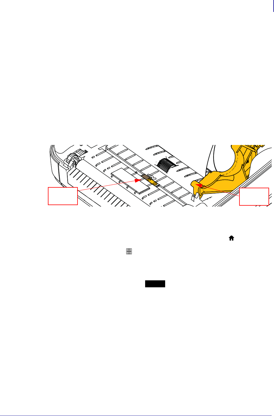
75
Printer Configuration
Manual Calibration - Media
1/16/2014 ZD500 Series™ Thermal Transfer Printer User’s Guide P1062653-002 Rev. A
Manual Calibration - Media
The printer may need to have the sensors and the label length adjusted for a new media. Small
variations in media from manufacture to manufacture and even from batch to batch of media
may necessitate recalibrating the printer for the media being used.
Use the Manual Calibration procedure when you change media unless to it media from the
same batch you have been using.
The primary method used to set the printer for media in use is the control panels SENSORS
menu to access the MANUAL CALIBRATION procedure. Use the following procedure to set
your printer’s language when the printer is turned on and in the ‘Ready’ state.
Procedure for calibration of label media with liner and inter-label ‘GAP’ between labels.
1. Load the printer with your chosen label media. Verify the media sensor is in the center
position for label gap (transmissive) sensing, see below.
2. Remove the first 3 inches or 80 mm of labels from the liner. Place the label-less liner over
the platen (driver roller) and the leading edge of the first label under the media guides.
3. Close the printer. Turn the printer power ON. Press the menus ‘Home’ ( ) button.
4. Navigate to the ‘SENSORS’ ( ) menu button and press the ‘Select’ () button.
5. Use the ‘Left’ () and ‘Right’ () navigation arrows to browse to the ‘MANUAL
CALIBRATION’ procedure.
6. Press the select button (—) below the START on the lower right hand of the display.
7. The display will have a message:
LOAD BACKING
PRINTER PAUSED
8. Press the Pause button once to start the calibration procedure.
9. When it has finished the first part of the calibration, the display will read:
RELOAD ALL
CONTINUE.
10. Press the Pause button once again to continue the calibration procedure. The printer will
begin feeding several labels and then it will stop with the display message reading:
READY
Remove excess media. Media calibration has finished and you are ready to print.
Center
Position
Media
Guide

Printer Configuration
RFID Calibration
76
P1062653-002 Rev. A ZD500 Series™ Thermal Transfer Printer User’s Guide 1/16/2014
RFID Calibration
RFID calibration sets communication parameters for your tag type. This procedure should be
done after the printer has been calibrated for the media (length and gap settings), typically a
Manual Media Calibration. During the RFID calibration process, the printer moves the media,
calibrates the RFID tag position, and determines the optimal settings for the RFID media being
used.
These settings include the programming position, the read/write power level to use, and reads
the tag's TID to determine the chip type (or choose F0 from the front panel RFID menu).
To restore the printer’s default programming position at any time, use the "restore" option in
the rfid.tag.calibrate SGD command.
Do not remove any labels or tag from the liner (label backing or ‘web’). This allows the printer
to determine RFID settings which do not encode adjacent tags. Allow a portion of media to
extend out the front of the printer to allow for backfeed during the tag calibration procedure.
Always do a Manual Media Calibration and RFID Calibration when you change media type. It
should not be necessary when simply replacing an empty roll of the same media.
Before beginning, load RFID media into the printer and perform the manual media
calibration.
1. Press the Feed button once to feed (advance) one label.
2. Press the menus ‘Home’ ( ) button. Navigate to the ‘RFID’ ( ) menu button and press
the ‘Select’ () button.
3. Use the ‘Left’ () and ‘Right’ () navigation arrows to browse to the ‘RFID
CALIBRATE’ procedure. Press the select button (—) below the START on the lower
right hand of the display.
4. The printer will slowly feed a label while adjusting the location and RFID read/write
communication settings for your chosen RFID tag/label.
The printer will feed an additional label in some cases when calibration has completed
successfully with the display message reading: READY
5. Remove excess media. Media calibration has finished and you are ready to print.

1/16/2014 ZD500 Series™ Thermal Transfer Printer User’s Guide P1062653-002 Rev. A
4
Print Operations
This section provides media and print handling, font and language support, and the setup of
less common printer configurations.
Print Operations
Determining Printer Configuration
78
P1062653-002 Rev. A ZD500 Series™ Thermal Transfer Printer User’s Guide 1/16/2014
Determining Printer Configuration
The ZD500 Series™ printer uses the configuration report to provide the printer’s status for
both ZPL. Operational status (darkness, speed, media type, etc.), installed printer options
(network, interface settings, cutter, etc.) and printer description information (serial number,
model name, firmware version, etc.) are all includes on the status label. See Test Printing with
Configuration Report Printouts on page 27 to print this label.
Thermal Printing
Modes of Printing
You can operate this printer in many different modes and media configurations:
• Direct thermal printing (which uses heat sensitive media to print).
• Thermal transfer printing (which uses ribbon to heat transfer print to the media).
• Standard Tear-Off mode allows you to tear off each label (or batch print a strip of labels)
after it is printed.
• Label Dispense Mode: If an optional dispenser is installed, the backing material can be
peeled away from the label as it is printed. After this label is removed, the next one is
printed.
• Media Cutting: If an optional media cutter is installed, the printer can cut the label liner
between labels, receipt paper or tag stock depending upon the cutter option purchased.
• Stand-alone: The printer can print without being connected to a computer using the
printer’s auto running label form feature (programming based) or by using a data input
device connected to the printer’s serial port. This mode accommodates data input devices,
such as scanners, weigh scales, a Zebra Keyboard Display Unit (ZKDU), etc.
• Shared network printing: Printers configured with the Ethernet interface option include an
internal print server with ZebraLink™ printer configuration web page and ZebraNet™
Bridge software for managing and monitoring status of Zebra® printers on a network.
Caution • The printhead becomes hot while printing. To protect from damaging the
printhead and risk of personal injury, avoid touching the printhead. Only use the cleaning
pen to perform printhead maintenance.
Caution • The discharge of electrostatic energy that accumulates on the surface of the
human body or other surfaces can damage or destroy the printhead or electronic
components used in this device. You must observe static-safe procedures when working
with the printhead or the electronic components under the top cover.

79
Print Operations
Types of Media
1/16/2014 ZD500 Series™ Thermal Transfer Printer User’s Guide P1062653-002 Rev. A
Setting the Thermal Print Method
The ZD500 Series™ printer has been designed to print in direct thermal and thermal transfer
modes. Press the menus ‘Home’ ( ) button. Navigate to the ‘SENSORS’ ( ) menu button
and press the ‘Select’ () button. Use the ‘Left’ () and ‘Right’ () navigation arrows to
browse to the ‘PRINT METHOD’. Use the Up () and Down () arrows to select DIRECT
THERMAL or THERMAL TRANS (transfer) media.
Types of Media
Your printer can use various types of media:
•Standard media—Most standard (non-continuous) media uses an adhesive backing that
sticks individual labels or a continuous length of labels to a liner.
•Continuous roll media—Most continuous roll media is direct thermal media (similar to
FAX paper) and is used for receipt or ticket style printing.
•Tag sto ck—Tags are usually made from a heavy paper (up to 0.0075in./0.19mm thick).
Tag stock does not have adhesive or a liner, and it is typically perforated between tags.
For more information on basic media types, see Table 15.
The printer typically uses roll media, but you can use fan-fold or other continuous media too.
Use the correct media for the type of printing you require. When printing without a ribbon, you
must use direct thermal media. When using ribbon, you must use thermal transfer media.
Determining Thermal Media Types
Thermal transfer media requires ribbon for printing while direct thermal media does not.
To determine if ribbon must be used with a particular media, perform a media scratch test.
To perform a media scratch test, complete these steps:
1. Scratch the print surface of the media with a finger nail or pen cap. Press firmly and
quickly while dragging it across the media surface. Direct thermal media is chemically
treated to print (expose) when heat is applied. This test method uses friction heat to expose
the media.
2. Did a black mark appear on the media?
Important • Zebra strongly recommends the use of Zebra-brand supplies for continuous
high-quality printing. A wide range of paper, polypropylene, polyester, and vinyl stock has
been specifically engineered to enhance the printing capabilities of the printer and to prevent
premature printhead wear. To purchase supplies, go to http://www.zebra.com/howtobuy.
Note - Zebra does not offer RFID media for sale at this time.
If a black mark... Then the media is...
Does not appear on the media Thermal transfer. A ribbon is required.
Appears on the media Direct thermal. No ribbon is required.
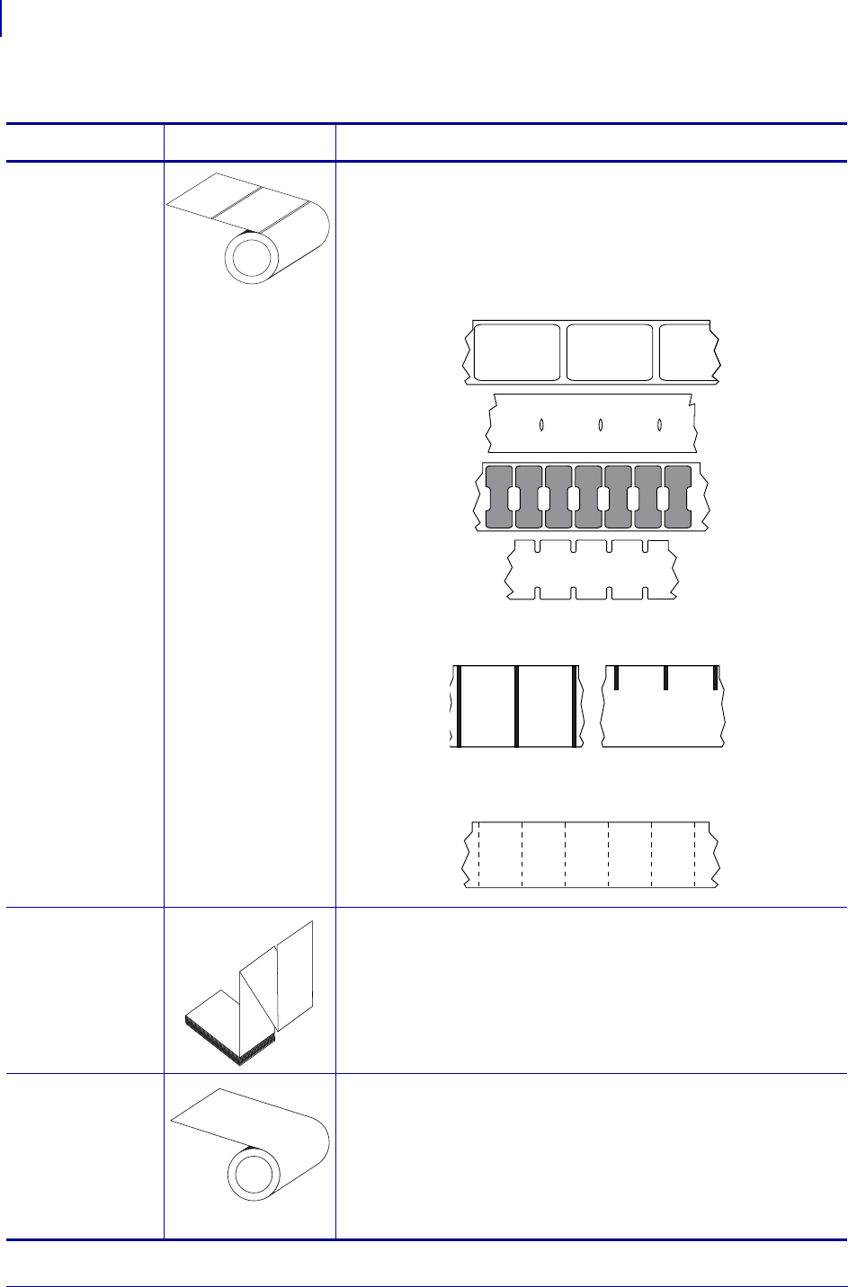
Print Operations
Types of Media
80
P1062653-002 Rev. A ZD500 Series™ Thermal Transfer Printer User’s Guide 1/16/2014
Table 15 • Types of Media Roll and Fanfold Media
Media Type How It Looks Description
Non-Continuous
Roll Media
Roll media is wound on a core that can be 0.5 to 1.5 in. (12.7 to
38.1 mm) in diameter. Labels have adhesive backing that sticks
them to a liner, and they are separated by gaps, holes, notches, or
black marks. Tags are separated by perforations. Individual labels
are separated by one or more of the following methods:
•Web media separates labels by gaps, holes, or notches.
•Black mark media uses pre-printed black marks on the back
side of the media to indicate label separations.
•Perforated media has perforations that allow the labels or tags
to be separated from each other easily. The media may also
have black marks or other separations between labels or tags.
Non-Continuous
Fanfold Media
Fan-Fold media is folded in a zigzag pattern. Fanfold media can
have the same label separations as non-continuous roll media.
The separations would fall on or near the folds.
Continuous
Roll Media
Roll media is wound on a core that can be 0.5 to 1.5 in. (12.7 to
38.1 mm) in diameter. Continuous roll media does not have gaps,
holes, notches, or black marks to indicate label separations. This
allows the image to be printed anywhere on the label. A cutter
can be used to cut apart individual labels. With continuous media,
use the transmissive (gap) sensor so the printer can detect when
the media runs out.
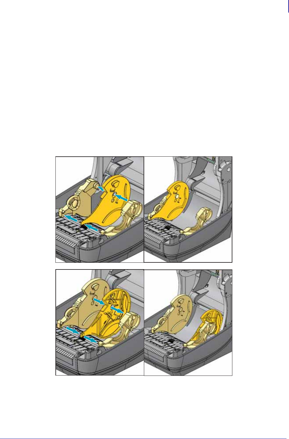
81
Print Operations
Media Loading
1/16/2014 ZD500 Series™ Thermal Transfer Printer User’s Guide P1062653-002 Rev. A
Media Loading
Use the 3 inch Core Adapters for media mounted on a 3 inch I.D. (Inner Diameter) rolls. The
maximum outside diameter of the roll is 5 inches.
Attaching the 3 inch Core Adapters
1. Open the printer.
2. Open the media roll holder. For easier access, the media guide stop adjustment can be
turned toward the front of the printer to lock open the media roll holders for easier access
to those roll holders.
3. Snap the core adapters onto the media roll holders. The hole on the adapter align with the
roll holder roll mount. the extended part of the adapter goes under the media guide in the
front of the media roll holder.
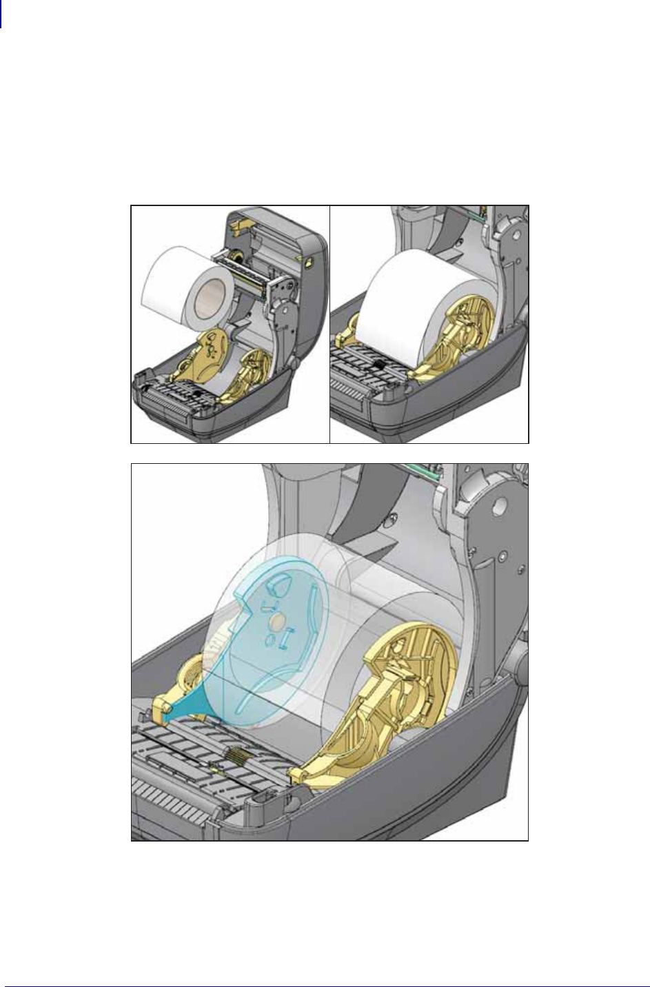
Print Operations
Media Loading
82
P1062653-002 Rev. A ZD500 Series™ Thermal Transfer Printer User’s Guide 1/16/2014
Loading 3 inch I.D. Media rolls
1. With the printer open and the 3 inch media core adapters installed, open the media roll
holders.
2. Place the media roll on the hangers on the top of the core adapters and let the media guides
close to hold the roll. Note you may need turn the media guide stop adjustment toward the
rear of the printer to allow the media roll holders to fully close on the media roll.
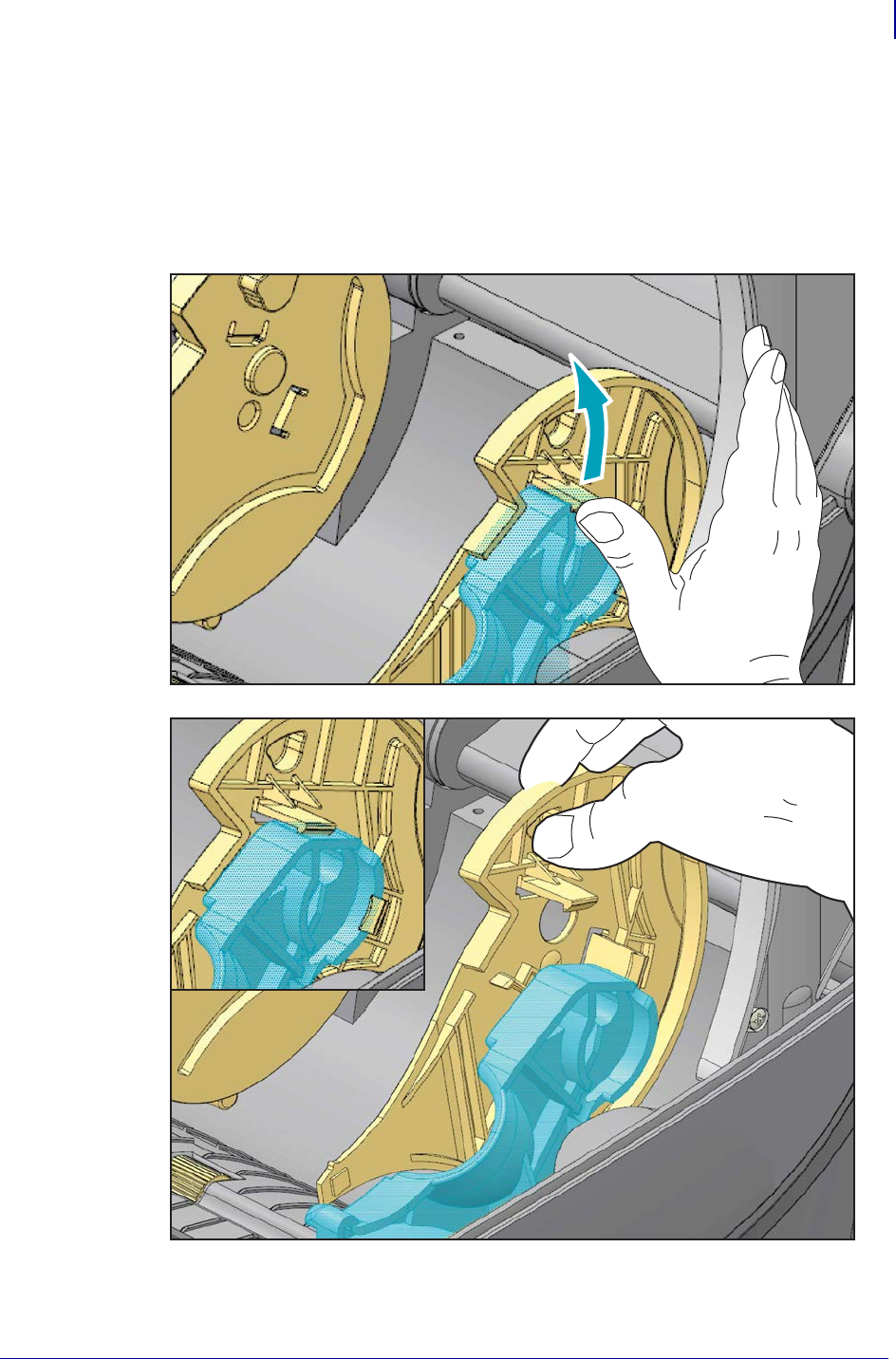
83
Print Operations
Media Loading
1/16/2014 ZD500 Series™ Thermal Transfer Printer User’s Guide P1062653-002 Rev. A
Removing the 3 inch Core Adapters
1. Open the printer and remove any media from the printer.
2. Push the locking tab on the backside of the core adapter. Push it up and towards the middle
of the printer. The core adapter will pop off the media roll holder.
3. Remove the other core adapter the same way.
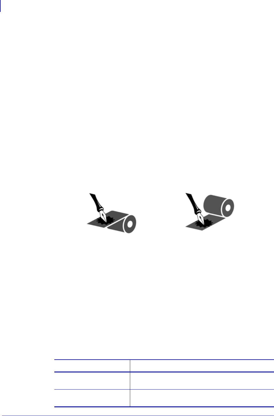
Print Operations
Ribbon Overview
84
P1062653-002 Rev. A ZD500 Series™ Thermal Transfer Printer User’s Guide 1/16/2014
Ribbon Overview
Ribbon is a thin film that is coated on one side with wax, resin, or wax resin, which is
transferred to the media during the thermal transfer process. The media determines whether
you need to use ribbon and how wide the ribbon must be. When ribbon is used, it must be as
wide as or wider than the media being used. If the ribbon is narrower than the media, areas of
the printhead are unprotected and subject to premature wear.
When to Use Ribbon
Thermal transfer media requires ribbon for printing while direct thermal media does not.
Direct thermal media should never be used with ribbon. Bar codes and graphics can get
distorted. To determine if ribbon must be used with a particular media, perform a media
scratch test.
Coated Side of Ribbon
Ribbon can be wound with the coated side on the inside or outside. This printer can only use
ribbon that is coated on the outside. If you are unsure which side of a particular roll of ribbon
is coated, perform an adhesive test or a ribbon scratch test to determine which side is coated.
To determine which side of a ribbon is coated, complete these steps:
Ribbon Test with Adhesive
If you have labels available, perform the adhesive test to determine which side of a ribbon is
coated. This method works well for ribbon that is already installed.
To perform an adhesive test, complete these steps:
1. Peel a label from its liner.
2. Press a corner of the sticky side of the label to the outer surface of the roll of ribbon.
3. Peel the label off of the ribbon.
4. Observe the results. Did flakes or particles of ink from the ribbon adhere to the label?
Outside Inside
If ink from the ribbon... Then...
Adhered to the label The ribbon is coated on the outside and can be used with
the printer.
Did not adhere to the label The ribbon is coated on the inside and can not be used in
the printer.

85
Print Operations
Ribbon Overview
1/16/2014 ZD500 Series™ Thermal Transfer Printer User’s Guide P1062653-002 Rev. A
Ribbon Scratch Test
Perform the ribbon scratch test when labels are unavailable.
To perform a ribbon scratch test, complete these steps:
1. Unroll a short length of ribbon.
2. Place the unrolled section of ribbon on a piece of paper with the outer surface of the
ribbon in contact with the paper.
3. Scratch the inner surface of the unrolled ribbon with your fingernail.
4. Lift the ribbon from the paper.
5. Observe the results. Did the ribbon leave a mark on the paper?
If the ribbon... Then...
Left a mark on the paper The ribbon is coated on the outside and can be used with
the printer.
Did not leave a mark on the
paper
The ribbon is coated on the inside and can not be used in
the printer.

Print Operations
Replacing Supplies
86
P1062653-002 Rev. A ZD500 Series™ Thermal Transfer Printer User’s Guide 1/16/2014
Replacing Supplies
If labels or ribbon run out while printing, leave the printer power on while reloading (data loss
results if you turn off the printer). After you load a new label or ribbon roll, press the Feed
button to restart.
Always use high quality, approved labels, tags and ribbons. If adhesive backed labels are used
that don’t lay flat on the backing liner, the exposed edges may stick to the label guides and
rollers inside the printer, causing the label to peel off from the liner and jam the printer.
Permanent damage to the printhead may result if a non-approved ribbon is used as it may be
wound incorrectly for the printer or contain chemicals corrosive to the printhead.
Adding a New Transfer Ribbon
If ribbon runs out in the middle of a print job, the indicator lights red and the printer waits for
you to add a fresh roll.
1. Keep the power on as you change ribbon.
2. Open the top cover, then cut the used ribbon so you can remove the cores.
3. Load a new ribbon roll and empty ribbon core. If necessary, review the Ribbon Loading
steps. Note: Do Not Use ribbon cores with damaged notch. The notches should have
square corners.
4. Close the top cover.
5. Press the Feed button to restart printing.
Replacing a Partially Used Transfer Ribbon
To remove used transfer ribbon, perform the following steps.
1. Cut the ribbon from the take-up roll.
2. Remove the take-up roll and discard used ribbon.
3. Remove the supply roll and tape the end of any fresh ribbon to prevent it from
unwrapping. When reinstalling a partially used supply roll, tape the cut end onto the
empty take-up roll.

87
Print Operations
Adjusting the Print Width
1/16/2014 ZD500 Series™ Thermal Transfer Printer User’s Guide P1062653-002 Rev. A
Adjusting the Print Width
Print width must be set when:
• You are using the printer for the first time.
• There is a change in media width.
Print width may be set by:
• The Windows printer driver or application software such as ZebraDesigner™.
• Using the control panel. Navigate as follows:
• Press the menus ‘Home’ ( ) button. Navigate to the ‘SETTINGS’ ( ) menu
button and press the ‘Select’ () button. Use the ‘Right’ () navigation arrow to
browse to ‘PRINT WIDTH’.Use the ‘Up’ () and ‘Down’ () navigation arrows to
change the print width. The print with is expressed in dots/pixels.
• Controlling printer operations with ZPL programming; refer to the Print Width (^PW)
command (consult your ZPL Programming Guide).
Adjusting the Print Quality
Print quality is influenced by the heat (density) setting of the printhead, the print speed, and the
media in use. Experiment with these settings to find the optimal mix for your application. Print
quality can be set with the Zebra Setup Utility’s ‘Configure Print Quality’ routine.
The relative darkness (or density) setting can be controlled by:
• Using the control panel. Navigate as follows:
• Press the menus ‘Home’ ( ) button. Navigate to the ‘SETTINGS’ ( ) menu
button and press the ‘Select’ () button. Use the ‘Right’ () navigation arrow to
browse to ‘DARKNESS’. Use the ‘Up’ () and ‘Down’ () navigation arrows to
change the darkness setting.
• The Set Darkness (~SD) ZPL command (consult your ZPL Programming Guide).
If you find that the print speed needs to be adjusted, use:
• The Windows printer driver or application software such as ZebraDesigner™.
• The Print Rate (^PR) command (consult your ZPL Programming Guide).
Use the printer’s ‘Print Quality Report’ (also know as FEED Self Test) to print a range of
labels used to allow you to identify changes to print DARKNESS and SPEED settings to
optimize general print and bar code quality. See the Print Quality Report on page 135 for
details.
Note • Media manufactures may have specific recommendations for speed settings for your
printer and the media. Some media types have lower maximum speeds than your printer’s
maximum speed.

Print Operations
Media Sensing
88
P1062653-002 Rev. A ZD500 Series™ Thermal Transfer Printer User’s Guide 1/16/2014
Media Sensing
The ZD500 Series™ printer media controls are set via a control panel setting or by sending
commands to the printer.
The printer’s media settings can be verified by printing a Printer Configuration label. See the
Test Printing with Configuration Report Printouts on page 27 for more details.
The maximum distance that the automatic media type detection and sensing will check can be
reduced by using the ZPL Maximum Label Length command (^ML). It is recommended that
this distance be set to no less than two times the longest label being printed. If the largest label
being printed was a 4 by 6 inch label, then the maximum label (media) length detection
distance can be reduced from the default distance of 39 inches down to 12 inches.
Table 16 • Media Settings
Menu Item Setting
MEDIA TYPE SETTINGS Menu on page 52 for media sensing method
TEAR OFF SETTINGS Menu on page 52 for setting the media
position after printing or a feed action.
PRINT MODE SETTINGS Menu on page 52 to set media handling after
printing or a feed action.
LABEL LENGTH MAX SETTINGS Menu on page 52 (see below for description).
POWER UP ACTION TOOLS Menu on page 56 to set what the media does on
power up.
HEAD CLOSE ACTION TOOLS Menu on page 56 to set what the media does when
the printer is closed.
MANUAL CALIBRATION Manual Calibration - Media on page 75 for the procedure
to automatically adjust the printer for typical label media.
TOOLS Menu on page 56 to start the manual calibration
process.
SENSOR PROFILE Sensor Profile on page 140 to observe and possibly
change media sensing for hard to calibrate media that for
example ‘has printing on the liner’ or ‘has pre-printe’
media‘ that can interfere with a manual calibration.
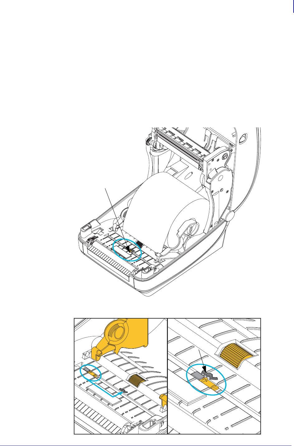
89
Print Operations
Using the Movable Black Mark Sensor
1/16/2014 ZD500 Series™ Thermal Transfer Printer User’s Guide P1062653-002 Rev. A
Using the Movable Black Mark Sensor
The movable black mark sensor allows the printer to use media with black marks or notches
(holes) on the back side of the media (or media liner) that are not located in the center of the
media.
The movable sensor’s second functional feature is adjustable transmissive web (gap) sensing
to positions that match legacy Zebra® desktop printer sensor locations and in between. This
provides for use of some non standard media variations or irregularly shaped media.
The movable black mark sensor can not properly sense continuous media or labels (for inter-
label gap sensing) if the sensor is not in the default sensing area for web (gap) sensing. See
Adjusting the Movable Sensor for Web (Gap) Sensing on page 92
Movable
Black Mark Sensor
Off Center
Black Mark Sensing Only
Default - Web (GAP) Sensing
Standard Operating Position
Alignment
Key
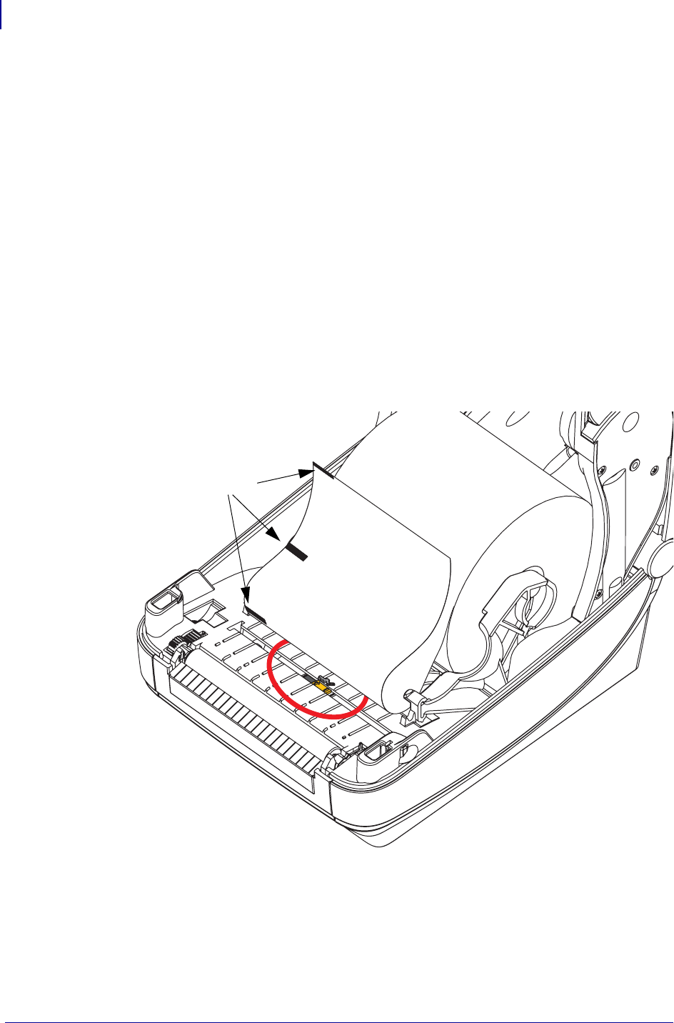
Print Operations
Using the Movable Black Mark Sensor
90
P1062653-002 Rev. A ZD500 Series™ Thermal Transfer Printer User’s Guide 1/16/2014
Adjusting the Movable Sensor for Black Marks or Notches
The black mark sensor looks for non-reflective surfaces such as black marks, black lines,
notches or holes in the media which do not reflect the sensor’s beam back to the sensor’s
detector. The sensor and it’s black mark detector are next to each other under the sensor cover
(dark plastic cover is translucent to the sensor’s non-visible light).
The sensor can be adjusted by two methods:
1) Preferred - Aligning the movable sensor’s alignment arrow to the right side of a black mark
or notch located in the center or left side of the printer, or
2) Align the center of the sensor cover under the oval notch or a right hand black mark (or
notch).
The sensor should be set as far as possible from the edge of media. The media can move from
side to side and notches cut into the side of the media can become damaged.
Load the media. Before closing the printer, adjust the moveable black mark sensor as follows:
1. Flip the media back over the roll to expose the black marks or notches on the backside
(non printing side) of the media.
Black Marks
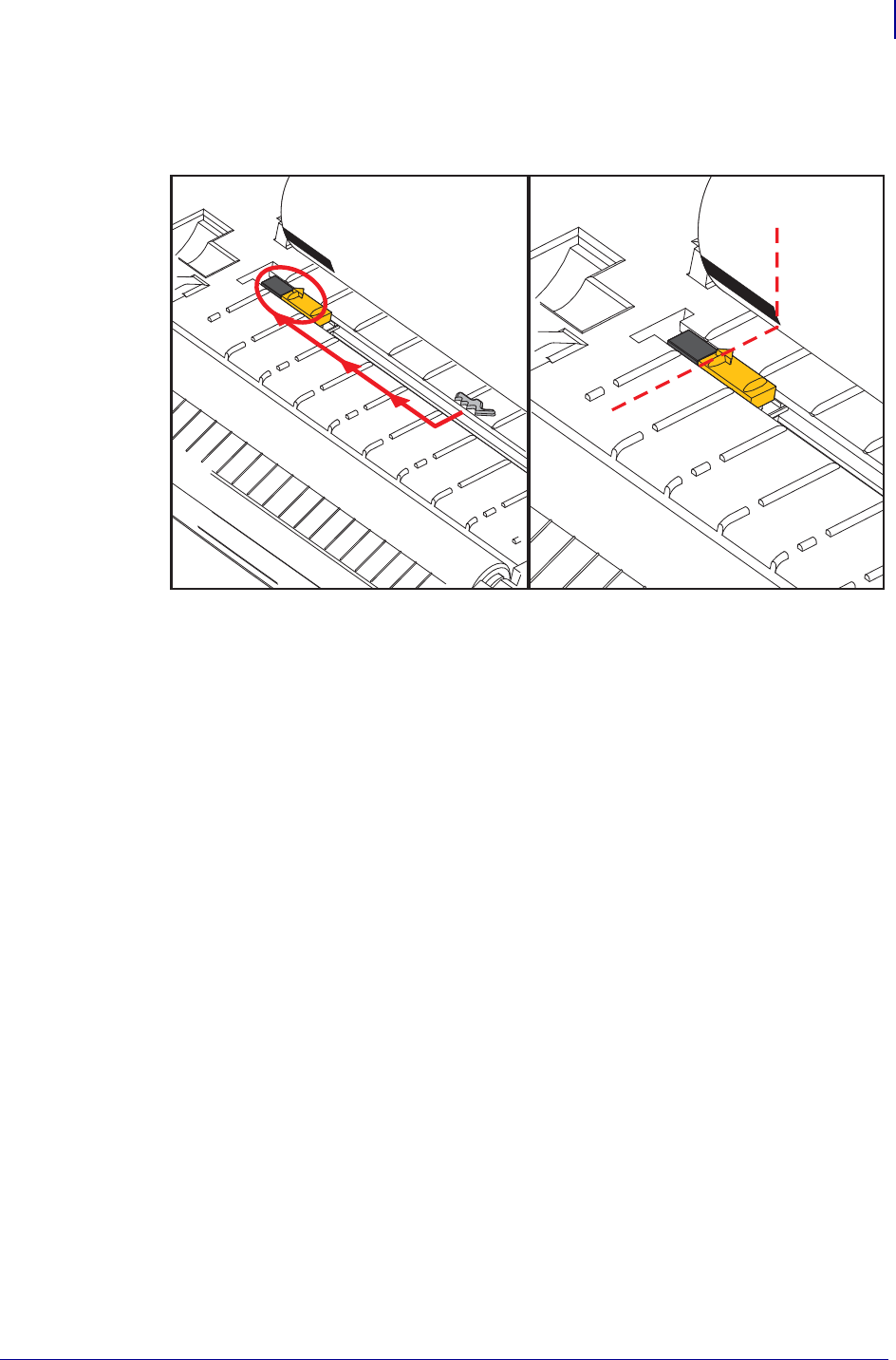
91
Print Operations
Using the Movable Black Mark Sensor
1/16/2014 ZD500 Series™ Thermal Transfer Printer User’s Guide P1062653-002 Rev. A
2. Slide the movable sensor from the center default position to align with the black marks.
The arrow on the movable sensor should line up with the right edge of the black mark.
This is true for marks or notches located on either side of the media (left side shown).
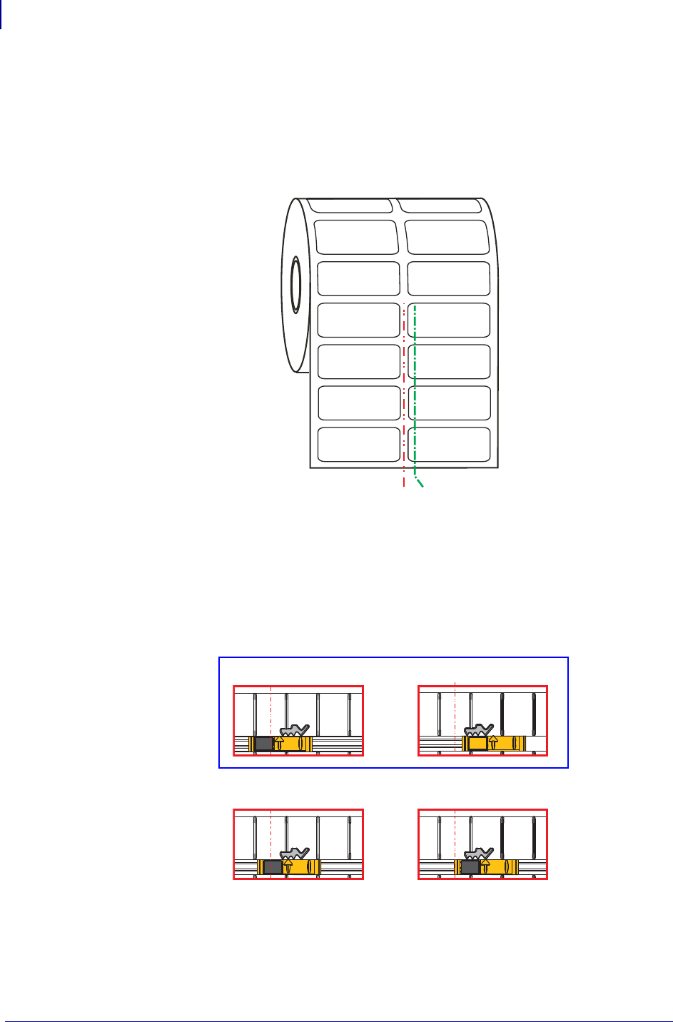
Print Operations
Using the Movable Black Mark Sensor
92
P1062653-002 Rev. A ZD500 Series™ Thermal Transfer Printer User’s Guide 1/16/2014
Adjusting the Movable Sensor for Web (Gap) Sensing
The movable sensor supports the web/gap positions used by the legacy Zebra® desktop printer
models and for some non standard media configurations. Printer’s with typical web (gap)
sensing in the fixed center position or the movable sensor’s set to the default position are offset
from the center of the printer to allow for gap sensing of labels that are side by side on a roll -
see below.
Web (Gap) sensing with the movable sensor can only function when the sensor’s alignment
arrow points to any position on the alignment key. The sensor must be aligned with the labels
(or other media) to sense the gap between the labels. The example above shows where the
sensor is set if center aligned positioning is used. It will miss sensing labels with a 2-up label
configuration and with the sensor in the ‘default’ position, it will be able to the detect labels
and the gaps between them.
• Default — Zebra Models: G-Series™ fixed position sensors, LP/TLP 2842™,
LP/TLP 2844™, LP/TLP 2042™
• Center Aligned — Zebra Model: LP/TLP 2742™
C
L
Default Gap
Sensing Position
Adjustment Range - Left to Right
DefaultCenter Aligned
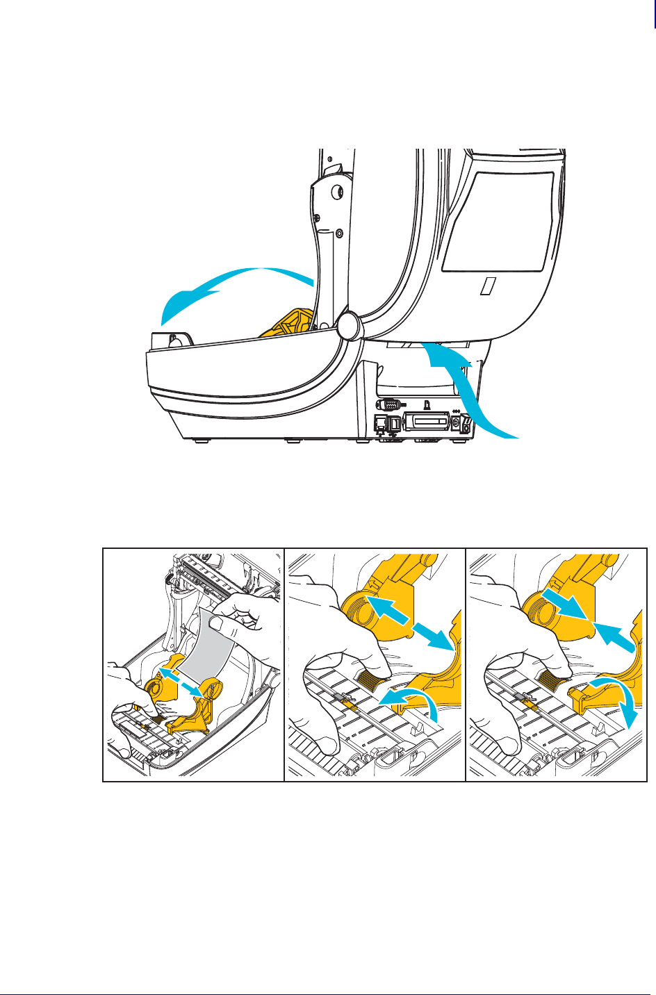
93
Print Operations
Printing on Fan-Fold Media
1/16/2014 ZD500 Series™ Thermal Transfer Printer User’s Guide P1062653-002 Rev. A
Printing on Fan-Fold Media
Printing on fan-fold media requires you to adjust the media guide’s stop position.
1. Open the top cover.
2. Adjust the media guide stop position with the green thumb wheel. Use a piece of the fan-
fold media to set the stop position. Rotate the wheel toward you to open the guides wider.
Rotate the wheel away from you to make the media guide narrower.
Fan-Fold
Media Path
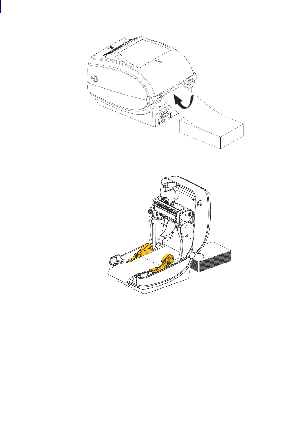
Print Operations
Printing on Fan-Fold Media
94
P1062653-002 Rev. A ZD500 Series™ Thermal Transfer Printer User’s Guide 1/16/2014
3. Insert the media through the slot at the rear of the printer.
4. Run the media between the media guide and roll holders.
5. Close the top cover.
After printing or feeding several labels: If the media does not track down the center (moves
from side to side) or the sides of the media (liner, tag, paper, etc.) are frayed or damaged when
exiting the printer, then the media guides may need further adjustment. If this does not correct
the problem, then the media can be routed over the two roll holding pins on the media guide.
An empty roll core of the same width as the stack of the fan-fold media can be placed between
the roll holders to provide additional support for thin media.

95
Print Operations
Printing with Externally Mounted Roll Media
1/16/2014 ZD500 Series™ Thermal Transfer Printer User’s Guide P1062653-002 Rev. A
Printing with Externally Mounted Roll Media
The printer accommodates externally mounted roll media similar to the printer’s support of
fan-fold media. The printer requires the media roll and stand combination to have a low initial
inertia to pull the media off the roll.
Zebra at this time does not offer an external media option for the ZD500 Series™ printer.
Externally Mounted Roll Media Considerations:
• The media ideally should enter the printer directly behind the printer through the fan-fold
media slot in the rear of the printer. See Printing on Fan-Fold Media on page 93 for media
loading.
• Lower the print speed to decrease the chance of motor stalls. The roll typically has the
highest inertia when trying to start the roll moving. Larger media roll diameters require the
printer to have more torque applied to get the roll moving.
• The media should move smoothly and freely. The media should not slip, skip, jerk, bind
and then move, etc. when mounted on your media stand.
• The printer should not touch the media roll.
• The printer should not slip or lift up off the operating surface.
Sending Files to the Printer
Graphics, fonts and programming files can be sent to the printer from the Microsoft Windows
operating systems by using the Zebra Setup Utilities (and driver), ZebraNet™ Bridge or
Zebra® ZDownloader found on the user's CD or at www.zebra.com.

Print Operations
Fonts and Your Printer
96
P1062653-002 Rev. A ZD500 Series™ Thermal Transfer Printer User’s Guide 1/16/2014
Fonts and Your Printer
The ZD500 Series™ printer supports your language and font requirements with a variety of
internal fonts, on-board font scaling, international font sets and character code page support,
Unicode support, and font download.
The printer’s font capabilities are programming language dependent. The ZPL™
programming language provides advanced font mapping and scaling technology to support
outline fonts (TrueType™ or OpenType™) and Unicode character mapping as well as basic
bitmapped fonts and character code pages. ZPL programming guide describes and documents
the fonts, code pages, character access, listing fonts, and limitations for their respective printer
programming languages. See the printer programming guides for information on Text, Fonts
and Character support.
The printer includes utilities and application software that support font download into the
printer for both printer programming languages.
Identifying Fonts in Your Printer
Fonts and memory are shared by the programming languages in the printer. Fonts can be
loaded in many memory areas in the printer. ZPL programming can recognize EPL and ZPL
fonts. EPL programming can only recognize EPL fonts. See the respective programmer guides
for more information on fonts and printer memory.
ZPL Fonts:
• To manage and download fonts for ZPL print operation, use the Zebra Setup utility or
ZebraNet™ Bridge.
• To display all of the fonts loaded in your printer, send the printer the ZPL command ^WD.
See the ZPL Programmers Guide for details.
• Bitmap fonts in the various printer memory areas are identified by the .FNT file
extension in ZPL.
• Scalable fonts are identified with the .TTF, .TTE or .OTF file extensions in ZPL.
EPL does not support these fonts.
Localizing the Printer with Code Pages
The ZD500 Series™ printer supports two sets of language, region and character sets for
permanent fonts loaded into the printer for each printer programming language, ZPL and EPL.
The printer supports localization with common international character map code pages.
• For ZPL code page support, including Unicode, see the ^CI command in the ZPL
programmer’s guide.

97
Print Operations
Fonts and Your Printer
1/16/2014 ZD500 Series™ Thermal Transfer Printer User’s Guide P1062653-002 Rev. A
Asian fonts and Other Large Font Sets
Asian language pictographic fonts have large character sets with thousands of characters that
support single language code page. In order to support the large Asian character sets, the
industry adopted a double-byte (67840 maximum) character system instead of the single-byte
characters (256 maximum) used by Latin based language characters to address large font sets.
In order to address multiple languages with a single font set, Unicode was invented. A
Unicode font supports one or more code points (relate these to code page character maps) and
is accessed in a standard method that resolves character mapping conflicts. The ZPL
programming language supports Unicode. Both of the printer’s programming languages
support the large pictographic double-byte character Asian font sets.
The number of fonts that can be downloaded is dependent upon the amount of available flash
memory not already in use and the size of the font to be downloaded.
Some Unicode fonts are large such as MS (Microsoft) Arial Unicode font (23 MB) available
from Microsoft or the Andale font (22 MB) offered by Zebra. These large font sets typically
support a large number of languages as well.
Getting Asian Fonts
Asian bitmap font sets are downloaded into the printer by the user or integrator. The ZPL fonts
are purchased separately from the printer. EPL Asian Fonts are available for free to download
from the Zebra Web site.
• Simplified and Traditional Chinese
• Japanese — JIS and Shift-JIS mappings
• Korean including Johab
•Thai

Print Operations
Fonts and Your Printer
98
P1062653-002 Rev. A ZD500 Series™ Thermal Transfer Printer User’s Guide 1/16/2014
Notes • ___________________________________________________________________
__________________________________________________________________________
__________________________________________________________________________
__________________________________________________________________________
__________________________________________________________________________
__________________________________________________________________________
__________________________________________________________________________
__________________________________________________________________________
__________________________________________________________________________
__________________________________________________________________________

1/16/2014 ZD500 Series™ Thermal Transfer Printer User’s Guide P1062653-002 Rev. A
5
Printer Options
This section covers the common printer options and accessories with brief descriptions and
how to get you started using or configuring your printer option or accessory.
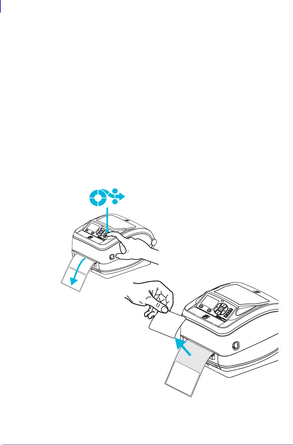
Printer Options
Label Dispenser Option
100
P1062653-002 Rev. A ZD500 Series™ Thermal Transfer Printer User’s Guide 1/16/2014
Label Dispenser Option
The factory installed label dispenser option allows you to print a label with backing
(liner/web) being removed from the label as it prints, ready for application. When printing
multiple labels, removing the dispensed (peeled) label notifies the printer to print and dispense
the next label.
To use dispenser-mode correctly, use your printer driver to activate the label (taken) sensor
along with these typical label settings which include but are not limited to length, non-
continuous (gap), and web (liner). Otherwise, you must send the ZPL programming
commands to the printer.
When programming in ZPL, you can use the following command sequences shown below
and refer to your ZPL Programming Guide for more information on ZPL programming.
^XA ^MMP ^XZ
^XA ^JUS ^XZ
1. Load your labels into the printer. Close the printer and press the Feed button until a
minimum of 4 inches or 100 millimeters of exposed labels exit the printer. Remove the
exposed labels from the liner.
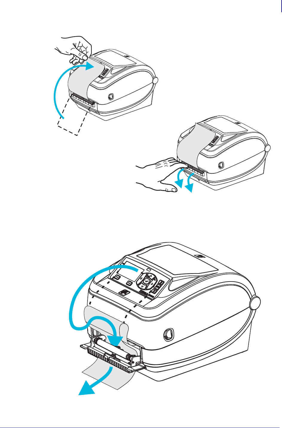
101
Printer Options
Label Dispenser Option
1/16/2014 ZD500 Series™ Thermal Transfer Printer User’s Guide P1062653-002 Rev. A
2. Lift the liner over the top of the printer and open the dispenser door.
3. Insert the label liner between the dispenser door and the printer body.
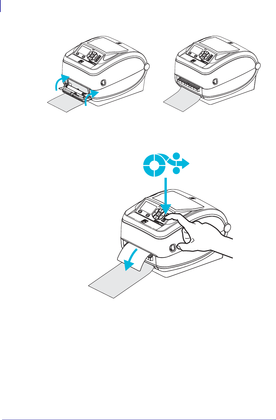
Printer Options
Label Dispenser Option
102
P1062653-002 Rev. A ZD500 Series™ Thermal Transfer Printer User’s Guide 1/16/2014
4. Close the dispenser door.
5. Press the Feed button to advance the media.
6. During the print job, the printer will peel off the backing and present a single label. Take
the label from the printer to allow the printer to print the next label. Note: If you did not
activate the label taken sensor to detect the removal of the dispensed (peeled) label with
software commands, the printer will stack and eject peeled labels.
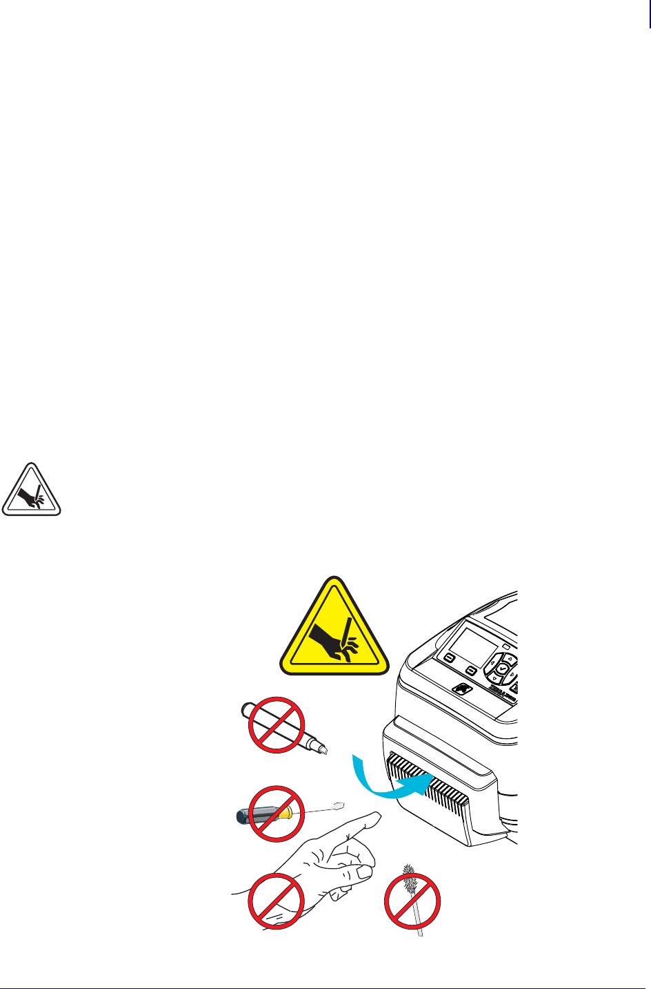
103
Printer Options
Cutter Option
1/16/2014 ZD500 Series™ Thermal Transfer Printer User’s Guide P1062653-002 Rev. A
Cutter Option
The printer supports a factory installed media cutter option for full width cutting of label liner,
tag or receipt media. These cutter options are all supported in a single cutter housing design.
The type of cutter option installed in your printer can be verified by printing a printer
configuration status label. The cutter options are:
•A medium duty cutter for cutting label liner and light tag media (LINER/TAG)
Maximum Paper Weight (thickness): up to 180 g/m2 (0.0077 in.)
Life*: 2 million cuts: 0.5 mil to 5 mil stock (10-120 g/m2)
1 million cuts: 5 mil to 7.5 mil stock (120-180 g/m2)
750,000 cuts: 7.5 mil to 10 mil (180-200 g/m2)
* - Exceeding the maximum media weight (density/hardness) and thickness will
shorten the cutters usable life or can cause the cutter to fail (jam or other error).
•Cut Width: 4.25 inches (108 mm) maximum to 0.75 inches (19 mm) minimum
•Minimum distance between cuts (label length): 1 inch (25.4 mm). Cutting shorter
media lengths between the cuts may cause the cutter to jam or error.
• By default, the cutter operations include a self cleaning preventive maintenance
cleaning cut after every twenty-fifth cut. This feature can be disabled via ZPL or SGD
(Set/Get/DO) programming command (cutter.clean_cutter) but is not
recommended.
Warning • There are no operator serviceable parts in the cutter unit. Never remove the
cutter cover (bezel). Never attempt to insert objects or fingers in to the cutter mechanism.
Important • Tools, cotton swabs, solvents (including alcohol), etc. all may damage or shorten
the cutter’s usable life or cause the cutter to jam.
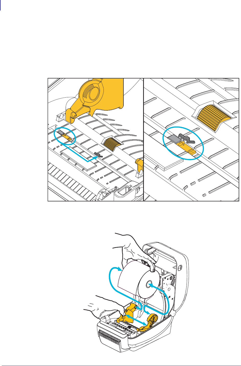
Printer Options
Cutter Option
104
P1062653-002 Rev. A ZD500 Series™ Thermal Transfer Printer User’s Guide 1/16/2014
Loading Media with the Cutter Option
1. Open the printer. Remember that you need to pull the release latch levers toward the front
of the printer.
2. Adjust the media sensor’s position for labels or continuous media to the center position. If
the media has black marks (not full width black lines) or notches, then see Adjusting the
Movable Sensor for Black Marks or Notches on page 90
3. Open the media roll holders. Pull the media guides open with your free hand and place the
media roll on the roll holders and release the guides. Orient the media roll so that its
printing surface will be up as it passes over the platen (drive) roller.
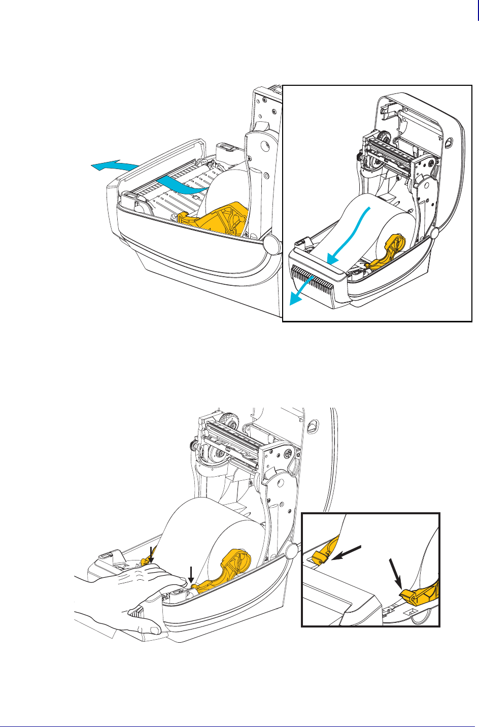
105
Printer Options
Cutter Option
1/16/2014 ZD500 Series™ Thermal Transfer Printer User’s Guide P1062653-002 Rev. A
4. Thread the media through the cutter’s inside slot so that it extends out of the front of the
printer. Verify the roll turns freely. The roll must not sit in the bottom of the media
compartment. Verify that media’s printing surface is facing up.
5. Push the media under both of the media guides.
6. Close the printer. Press down until the cover snaps closed.
Under Media
Guides

Printer Options
ZebraNet® Internal Wireless Print Server Option
106
P1062653-002 Rev. A ZD500 Series™ Thermal Transfer Printer User’s Guide 1/16/2014
ZebraNet® Internal Wireless Print Server Option
The ZebraNet® Internal Wireless Print Server (PS) is an optional factory installed device that
connects to Wi-Fi network access point on your network and your ZebraLinkTM-enabled
printer. The print server provides you with a browser interface for printer and print server
settings. If you use the ZebraNetTM Bridge, Zebra® network printer management software,
you can easily access the specialized features of a ZebraLinkTM enabled printer.
Printers with an Internal Wireless Print Server provide the following features:
• A printer status display for alerts, configuration settings and network settings.
• Print server and printer setup using a browser.
• Remote monitoring and configuration capability of the Internal Wireless PS using a
browser.
•Alerts.
• The ability for you to send unsolicited printer status messages via E-mail-enabled
devices.
ZebraNetTM Bridge — ZebraNetTM Bridge is a software program that works with the
10/100 Internal PS and enhances the features of ZebraLink resident within ZPL-based printers.
The features include the following:
•ZebraNet
TM Bridge allows you to locate printers automatically. ZebraNetTM Bridge
searches on parameters such as IP address, subnet, printer model, printer status, and
many other user-defined characteristics.
• Remote Configuration — Manage all your Zebra label printers throughout the
enterprise without having to travel to remote sites or physically handle any printers.
Any Zebra printer connected to the enterprise network can be accessed from the
ZebraNetTM Bridge interface and configured remotely through an easy-to-use
graphical user interface.
• Printer Alerts, Status, Heartbeat Monitoring and event Notification — ZebraNetTM
Bridge lets you configure multiple event alerts per device with different alerts directed
to different people. Receive alerts and notifications by e-mail, cell phone/pager, or
through the ZebraNetTM Bridge Events tab. View alerts by printer or group, and filter
by date/time, severity, or trigger.
• Configure and Copy Printer Profiles — Copy and paste settings from one printer to
another or broadcast them to an entire group. ZebraNet Bridge allows you to copy
printer settings, printer-resident files (formats, fonts, and graphics), and alerts with a
click of the mouse. Create printer profiles — virtual “golden printers” — with desired
settings, objects, and alerts, and clone or broadcast them as if they were real printers,
providing extensive savings in setup time. Printer profiles are also an excellent way to
back up a printer’s configuration for crisis recovery.

107
Printer Options
Bluetooth Option
1/16/2014 ZD500 Series™ Thermal Transfer Printer User’s Guide P1062653-002 Rev. A
Bluetooth Option
Bluetooth is an optional factory installed (internal wireless) device that can connect to other
Bluetooth enabled devices and computers. The Bluetooth radio inside ZD500 Series™ printers
complies with Bluetooth Specification 3.0 and supports the Serial Port Profile (SPP), a
Windows virtual serial port. All print jobs sent to the printer on Windows PC’s will be done
through the SPP, which is basically a Bluetooth emulation of an RS-232 serial communication.
This printer option includes a LCD display to provide connection status and configuration
information to assist with installation and connection to a Bluetooth enabled host system.
Microsoft has supported most Bluetooth devices since the release of Windows XP Service
Pack 2 (SP2). Prior to that, Bluetooth devices for earlier versions of Windows required drivers
to be supplied with the device. Windows XP SP2 and above also include ‘Add a Printer’
wizard support for printers. The ZD500 Series™ printer is accessed via a Bluetooth virtual
serial port connection (SPP). The printer only needs Bluetooth 2.0 driver that supports SPP to
be able to communicate with the Windows PC’s Bluetooth devices.
In the Windows environment, the printer requires the ZebraDesigner™ driver to be installed
on the computer to enable printing after Bluetooth communication has been established. Use
the Zebra Setup Utility’s printer install wizards to help you configure your Bluetooth
connection.
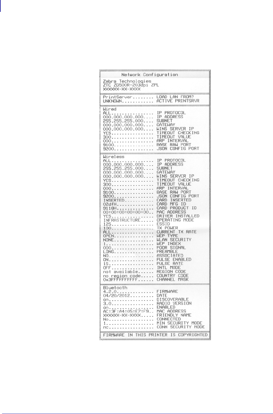
Printer Options
Bluetooth Option
108
P1062653-002 Rev. A ZD500 Series™ Thermal Transfer Printer User’s Guide 1/16/2014
Printer Network Configuration Status Label
ZD500 Series™ printers with the ZebraNet® Internal Wireless Print Server option on-board
print an additional printer configuration status label for information needed to establish and
trouble shoot network printing. The following printout is printed with the ZPL ~WL
command.
The regular printout of the configuration status label has some of the printer’s network settings
such as IP Address, on the lower half of the printout.
The printer’s IP address is needed to identify and configure the printer for operations on your
network. See the ZebraNet® Internal Wireless Print Server manual for more information.

1/16/2014 ZD500 Series™ Thermal Transfer Printer User’s Guide P1062653-002 Rev. A
6
Maintenance
This section provides routine cleaning and maintenance procedures.

Maintenance
Cleaning
110
P1062653-002 Rev. A ZD500 Series™ Thermal Transfer Printer User’s Guide 1/16/2014
Cleaning
When you clean the printer, use one of the following supplies that best suits your needs:
You can obtain cleaning supplies at www.zipzebra.com.
The cleaning process takes just a couple of minutes using the steps outlined below.
Cleaning Supplies Order
Quantity Intended Purpose
Cleaning pens (105950-035) Set of 12 Clean printhead
Cleaning swabs (105909-057) Set of 25 Clean media path, guides and sensors
Printer Part Method Interval
Printhead Let the printhead to cool for a minute, then use a
new cleaning pen to swab the dark line on the
printhead cleaning from the center to the outside
edges of the printhead.
See Cleaning the Printhead on page 111
When using ribbon:
after every roll of
ribbon; when using
direct thermal: after
every roll of media.
Platen roller Remove the platen roller to clean. Clean the
roller thoroughly with 90% medical-grade
alcohol and a cleaning swab or lint-free cloth.
See Platen Cleaning and Replacement
on page 114
As needed.
Peel bar Clean it thoroughly with 90% medical-grade
alcohol and a fiber-free cleaning swab.
Let alcohol dissipate and the printer dry
completely.
Media path
Cutter Option The cutter blade mechanism does not require
maintenance cleaning. DO NOT Clean the blade
or mechanism with solvents or WD-40. This
blade has a special coating to resist adhesives
and wear.
Exterior Water-dampened cloth. As needed.
Interior Gently brush out printer.
Caution • Adhesives and media material can over time transfer onto the printer
components along the media path including the platen and printhead. This build-up can
accumulate dust and debris. Failure to clean the printhead, media path and platen roller
could result in inadvertent loss of labels, label jams and possible damage to the printer.
Important • Using too much alcohol can result in contamination of the electronic
components requiring a much longer drying time before the printer will function properly.
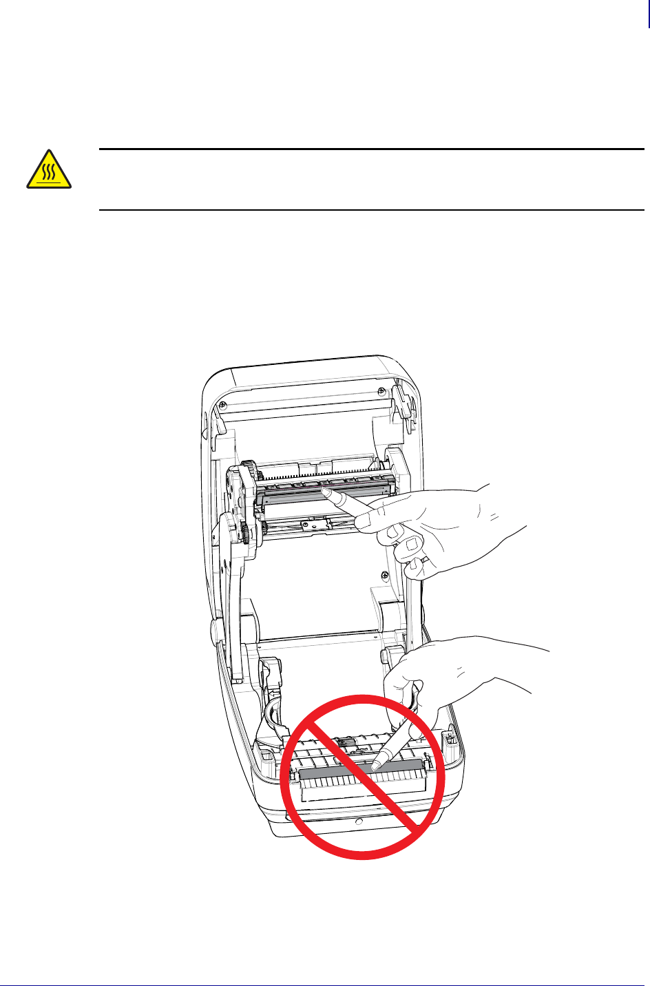
111
Maintenance
Cleaning
1/16/2014 ZD500 Series™ Thermal Transfer Printer User’s Guide P1062653-002 Rev. A
Cleaning the Printhead
Always use a new cleaning pen on the printhead (an old pen carries contaminants from its
previous uses that may damage the printhead).
When you load new media, you can also clean the printhead.
1. Rub the cleaning pen across the dark area of the printhead. Clean from the middle to the
outside. This will move adhesive transferred from the edges of media to the printhead
outside of media path.
2. Wait one minute before closing the printer.
Caution • The printhead becomes hot while printing. To protect from damaging the
printhead and risk of personal injury, avoid touching the printhead. Use only the cleaning
pen to perform maintenance.
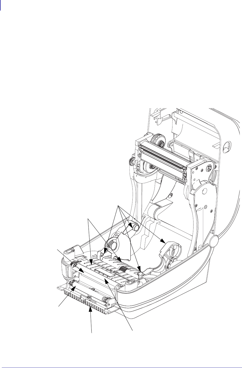
Maintenance
Cleaning
112
P1062653-002 Rev. A ZD500 Series™ Thermal Transfer Printer User’s Guide 1/16/2014
Media Path Cleaning
Use a cleaning swab to remove debris, dust or crust that has built-up on the holders, guides and
media path surfaces.
1. Use the alcohol in the cleaning swab to soak the debris to break up the adhesive.
2. Wipe the ridges to remove accumulated debris.
3. Wipe the inside edges of both edge guides to remove any built-up residue.
4. Wait one minute before closing the printer.
Discard the cleaning swab after use.
Media
Guides
Ridges
Platen
Peel
Bar
Pinch
Roller
Ridges
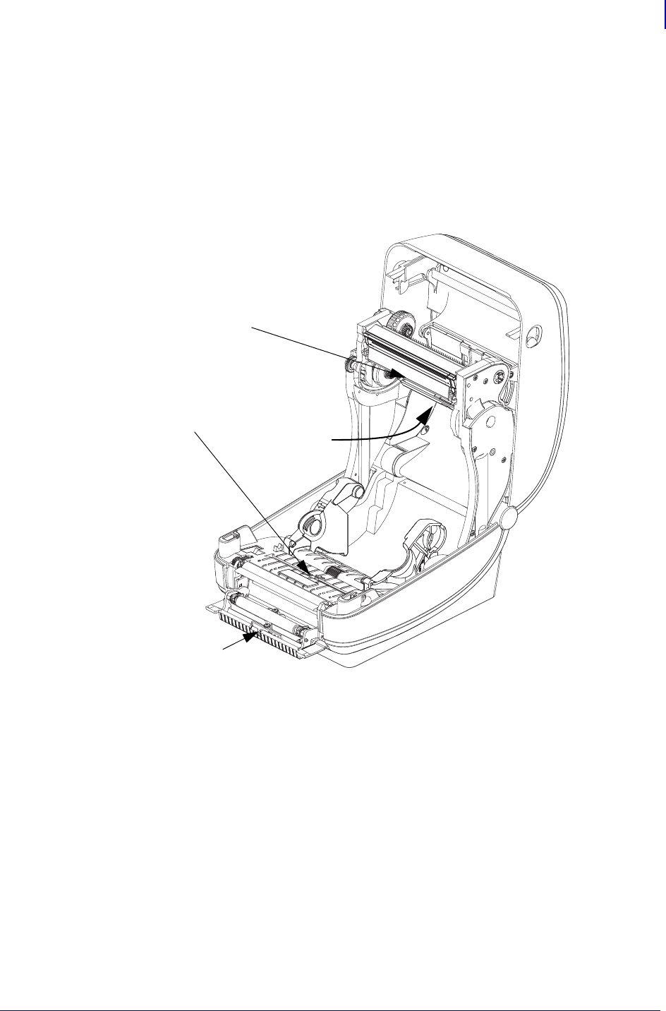
113
Maintenance
Cleaning
1/16/2014 ZD500 Series™ Thermal Transfer Printer User’s Guide P1062653-002 Rev. A
Sensor Cleaning
Dust can accumulate on the media sensors.
1. Gently brush away dust; if necessary, use a dry swab to brush away dust. If adhesives or
other contaminates remain, use an alcohol moistened swab to break it up.
2. Use a dry swab to remove any residue that may be left from the first cleaning.
3. Repeat steps 1 and 2 as required until all residue and streaks are removed from the sensor.
.
Black-Line
Sensor
Ribbon Trailer
Sensor
Label Taken
Sensor
Gap
Sensor
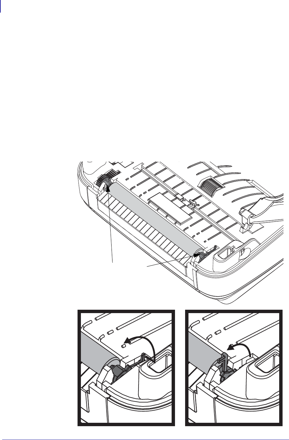
Maintenance
Cleaning
114
P1062653-002 Rev. A ZD500 Series™ Thermal Transfer Printer User’s Guide 1/16/2014
Platen Cleaning and Replacement
The standard platen (drive roller) normally does not require cleaning. Paper and liner dust can
accumulate without effecting print operations. Contaminates on the platen roller can damage
the printhead or cause the media to slip or stick when printing. Adhesive, dirt, general dust,
oils and other contaminates should be cleaned immediately off the platen.
Clean the platen (and media path) whenever the printer has significantly poorer performance,
print quality or media handling. The platen is the print surface and drive roller for your media.
If sticking or jamming continues even after cleaning, you must replace the platen.
The platen can be cleaned with a fiber-free swab (such as a Texpad swab) or a lint free, clean,
damp cloth very lightly moistened with medical grade alcohol (90% pure or better).
1. Open the cover (and dispenser door). Remove media from platen area.
2. Pull the platen bearing latch release tabs on the right and left sides towards the front of the
printer and rotate them up.
Platen Bearings
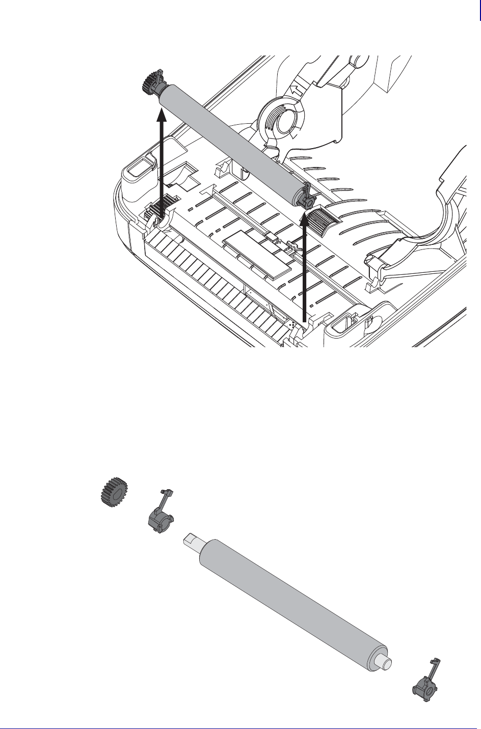
115
Maintenance
Cleaning
1/16/2014 ZD500 Series™ Thermal Transfer Printer User’s Guide P1062653-002 Rev. A
3. Lift the platen out of the printer’s bottom frame.
4. Clean the platen with the alcohol moistened swab. Clean from the center out. Repeat this
process until the all of the roller surface has been cleaned. If there has been heavy
adhesive build-up or label jam, repeat with a new swab to remove residual contaminates.
Adhesives and oils, for example, may be thinned by the initial cleaning but not completely
removed.
5. Install the platen in the printer. Discard the cleaning swabs after use - do not reuse.
6. Make sure the bearings and drive gear are on the shaft of the platen.
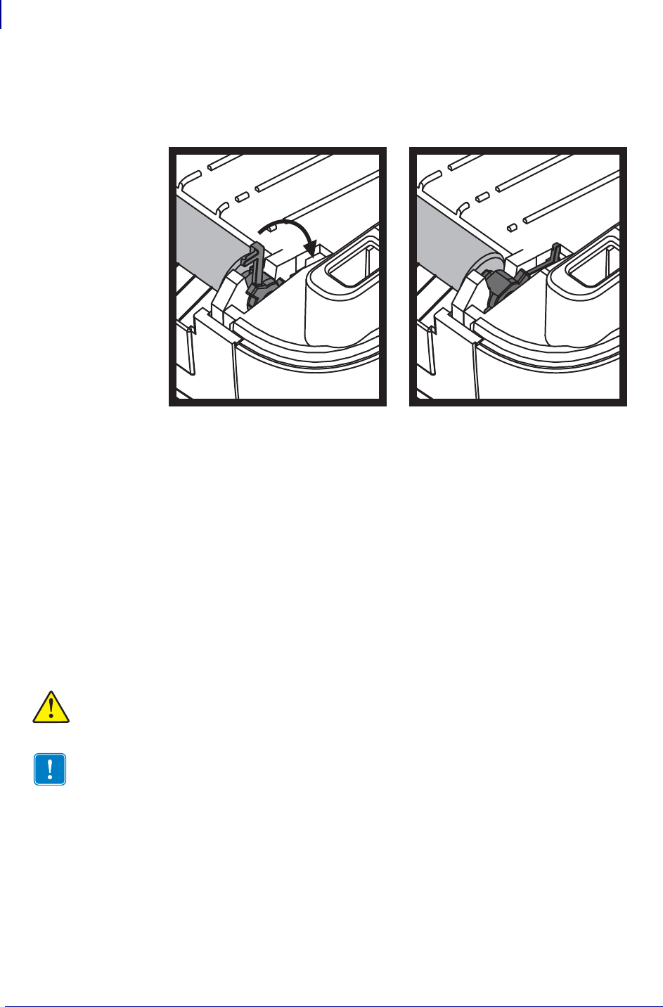
Maintenance
RTC Battery
116
P1062653-002 Rev. A ZD500 Series™ Thermal Transfer Printer User’s Guide 1/16/2014
7. Align the platen with the gear to the left and lower it into the printer’s bottom frame.
8. Rotate the platen bearing latch release tabs down on the right and left sides towards the
rear of the printer and snap them into place.
Allow the printer to dry for one minute before closing the dispenser door, media cover or
loading labels.
Other Printer Maintenance
There are no user level maintenance procedures beyond those detailed in this section. See the
Troubleshooting on page 123 for more information on diagnosing printer and print problems.
RTC Battery
The RTC (Real-Time Clock) battery is not operator replaceable. See a Zebra authorized
service technician to replace the battery.
Fuses
There are no replaceable fuses in the ZD500 Series™ printer or power supply.
Caution • The printer has a three volt lithium battery. You can discern a low or flat battery if
the printer provides a consistently delayed date stamp. Battery replacement must be performed
by a qualified service technician. Only use a Zebra approved replacement battery.
Important • Recycle batteries according to local your guidelines and regulations. Wrap the
battery when disposing (or storing) to avoid a short circuit.
DO NOT short circuit the battery. Short circuiting the battery may result in heat
generation, fire or bursting.
DO NOT heat, disassemble or dispose of battery in fire.
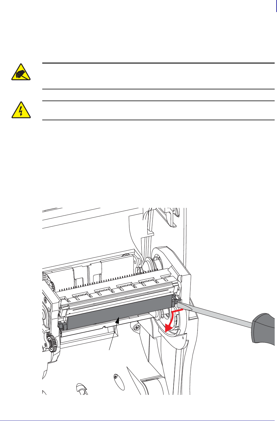
117
Maintenance
Replacing the Printhead
1/16/2014 ZD500 Series™ Thermal Transfer Printer User’s Guide P1062653-002 Rev. A
Replacing the Printhead
If you need to replace the printhead, read the procedure and review the removal and
installation steps before actually replacing the printhead.
Before following the steps in this procedure, open the printer by pulling the release latches
forward then lifting the top cover.
Printhead Removal
1. Open the printer. Remove any transfer ribbon from the printer.
2. Use a small flat bladed screwdriver to remove the ribbon guide. Gently pry the guide
right-side tab from the ribbon frame. Pull the left side of the ribbon guide out.
Caution • Prepare your work area by protecting against static discharge. Your work area
must be static-safe and include a properly grounded conductive cushioned mat to hold the
printer and a conductive wrist strap for yourself.
Caution • Turn the printer power off and unplug the power cord before replacing the
printhead.
Ribbon Guide
(and printhead cover)
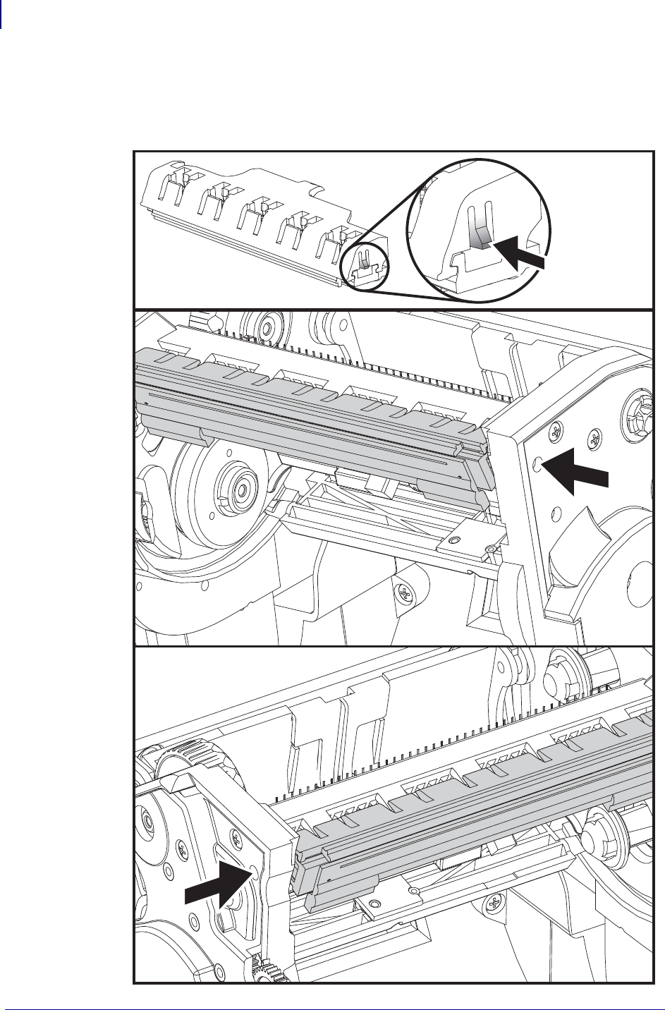
Maintenance
Replacing the Printhead
118
P1062653-002 Rev. A ZD500 Series™ Thermal Transfer Printer User’s Guide 1/16/2014
3. Use a blunt tipped tool to press the release tab on the right side and then the left side of the
printhead. The tool diameter can be from 0.10 to 0.15 inches (2.5 to 3.8 mm).
Insert the tool into the ribbon frame's printhead release access (the round) opening. Push
the release tab and gently pull the printhead bracket down.
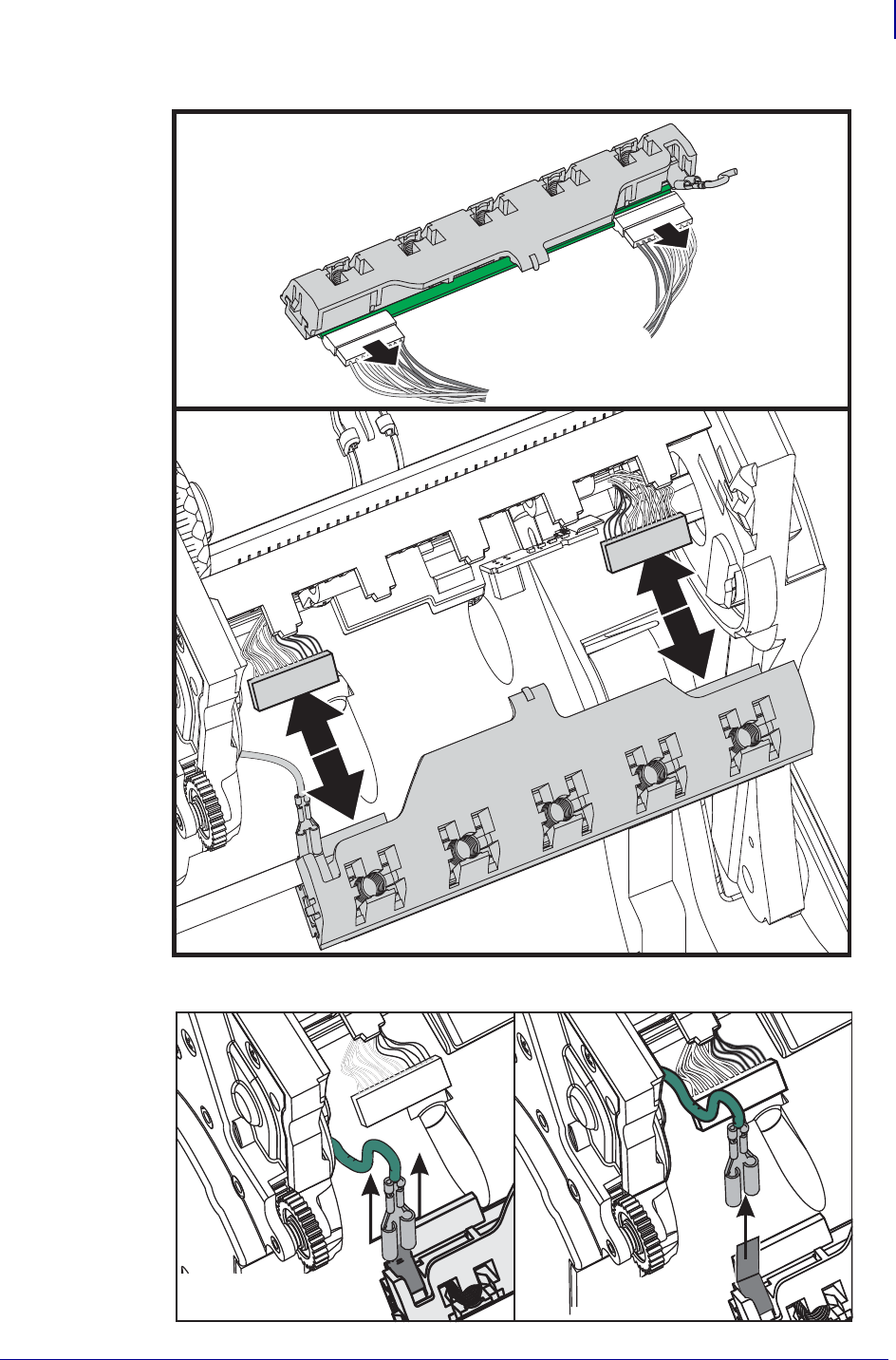
119
Maintenance
Replacing the Printhead
1/16/2014 ZD500 Series™ Thermal Transfer Printer User’s Guide P1062653-002 Rev. A
4. Gently but firmly pull the two printhead cable bundles’ connectors off of the printhead.
5. Gently but firmly pull the green ground wire off the printhead.
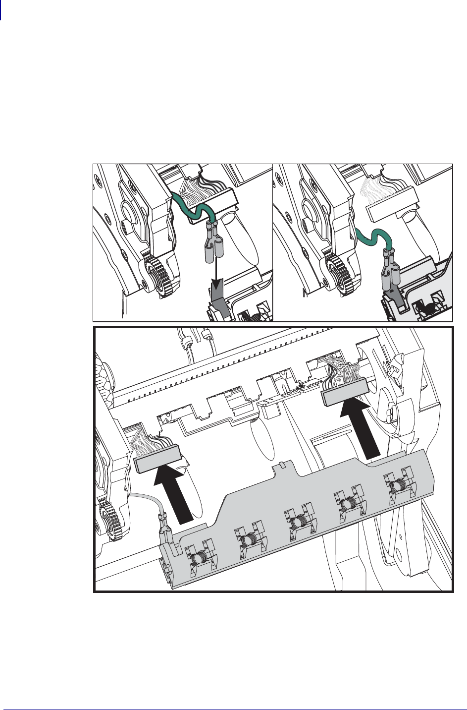
Maintenance
Replacing the Printhead
120
P1062653-002 Rev. A ZD500 Series™ Thermal Transfer Printer User’s Guide 1/16/2014
Replacing the Printhead
1. Push the left side printhead connector into the printhead. The connector is keyed to only
insert one way.
2. Connect the green ground wire to the printhead.
3. Push the right side printhead wire connector onto the printhead.
4. Check that the ground wire and wire bundles are still connected to the printhead.
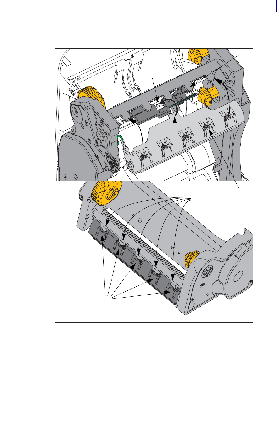
121
Maintenance
Replacing the Printhead
1/16/2014 ZD500 Series™ Thermal Transfer Printer User’s Guide P1062653-002 Rev. A
5. Insert the printhead bracket’s the tab into slot in the ribbon frame assembly. Align the
printhead spring slots to the five posts and snap the printhead into the ribbon frame.
Slot
Post
Spring
Slot
Tab
Spring
Slot
Spring
Post
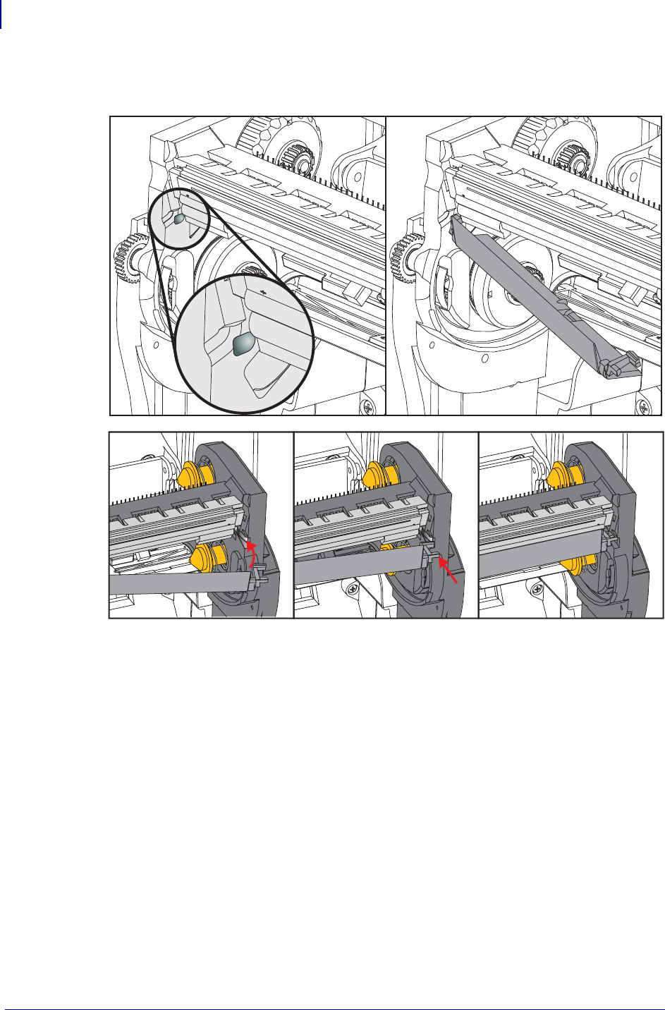
Maintenance
Replacing the Printhead
122
P1062653-002 Rev. A ZD500 Series™ Thermal Transfer Printer User’s Guide 1/16/2014
6. Place the left hand side of the ribbon guide into the ribbon frame. Swing the right side of
the ribbon guide into the slot and snap it into position.
7. Verify that the printhead moves up and down freely when pressure is applied and remains
locked when released.
8. Clean the printhead. Use a new pen to wipe body oils (finger prints) and debris of the
printhead. Clean from the center of the printhead to the outside. See Cleaning the
Printhead on page 111.
9. Reload media. Plug in the power cord, turn on the printer and print a status report to
ensure proper function. See Test Printing with Configuration Report Printouts on page 27.

1/16/2014 ZD500 Series™ Thermal Transfer Printer User’s Guide P1062653-002 Rev. A
7
Troubleshooting
This section provides troubleshoots procedures.
Troubleshooting
Error Messages
124
P1062653-002 Rev. A ZD500 Series™ Thermal Transfer Printer User’s Guide 1/16/2014
Error Messages
The control panel displays messages when there is an error. See Table 1 for errors, the possible
causes, and the recommended solutions.
Table 1 • Error Messages
Display/
Indicator Lights Possible Cause Recommended Solution
STATUS light steady red
The printhead is not fully
closed.
Close the printhead
completely.
The printhead open sensor is
not working properly.
Call a service technician to
replace the sensor.
STATUS light steady red
The media is not loaded or is
loaded incorrectly.
Load media correctly.
Misaligned media sensor. Check the position of the
media sensor.
The printer is set for
noncontinuous media, but
continuous media is loaded.
1. Install the proper media
type, or reset printer for the
current media type.
2. Calibrate the printer. See
Manual Calibration -
Media on page 75.
STATUS light steady red
In thermal transfer mode:
•the end of the ribbon roll
has been detected.
Replace the empty ribbon with
a new roll.
STATUS light flashing red
The printhead damaged,
replace incorrectly, or was
replaced with one that is not a
genuine Zebra™ printhead.
Install a genuine Zebra™
printhead.
STATUS light steady yellow
Caution • The printhead may be hot enough to cause
severe burns. Allow the printhead to cool.
The printhead is over
temperature.
Allow the printer to cool.
Printing automatically resumes
when the printhead elements
cool to an acceptable operating
temperature.
If this error persists, consider
changing where the printer is
located or using a slower print
speed.
HEAD OPEN
CLOSE HEAD
MEDIA OUT
LOAD MEDIA
ALERT
RIBBON OUT
PH NOT AUTHENTICATED
REPLACE PRINTHEAD
PRINT HEAD OVERTEMP
PRINTING HALTED
125
Troubleshooting
Error Messages
1/16/2014 ZD500 Series™ Thermal Transfer Printer User’s Guide P1062653-002 Rev. A
STATUS light steady yellow
The printer shows one of these messages
or cycles between them.
Caution • An improperly connected printhead data or
power cable can cause these error messages. The
printhead may be hot enough to cause severe burns.
Allow the printhead to cool.
The printhead data cable is not
properly connected.
Call a service technician to
hook up the printhead
properly.
The printhead has a faulty
thermistor.
Call a service technician to
replace the printhead.
The printhead temperature is
approaching its lower
operating limit.
Continue printing while the
printhead reaches the correct
operating temperature. If the
error remains, the environment
may be too cold for proper
printing. Relocate the printer
to a warmer area.
STATUS light steady red
Caution • The cutter blade is sharp. Do not touch or
rub the blade with your fingers.
The cutter blade is in the
media path. Cutter maybe
obstructed (jammed).
The cutting blade is stopped.
Needs service if cycling power
or running cut cycles with the
SGD cutter.clean_cutter
command can not clear the
obstruction. See the ZPL
Programming Guide for more
information..
There is not enough memory
to perform the function
specified on the second line of
the error message.
Free up some of the printer’s
memory by adjusting the label
format or printer parameters.
One way to free up memory is
to adjust the print width to the
actual width of the label
instead of leaving the print
width set to the default. See
SETTINGS Menu on page 52 -
PRINT WIDTH.
Ensure that the data is not
directed to a device that is not
installed or is unavailable.
If the problem persists, call a
service technician.
Table 1 • Error Messages (Continued)
Display/
Indicator Lights Possible Cause Recommended Solution
HEAD COLD
PRINTING HALTED
THERMISTOR
REPLACE PRINTHEAD
CUT ERROR
OUT OF MEMORY
STORING GRAPHIC
OUT OF MEMORY
STORING FORMAT
OUT OF MEMORY
STORING BITMAP
OUT OF MEMORY
STORING FONT

Troubleshooting
Printing Issues
126
P1062653-002 Rev. A ZD500 Series™ Thermal Transfer Printer User’s Guide 1/16/2014
Printing Issues
This section helps you identify possible issues with printing or print quality, the possible
causes, and the recommended solutions.
Table 2 • Printing Issues
Issue Possible Cause Recommended Solution
General print quality
issues - The printed
image does not look
right.
The printhead is dirty. Clean the printhead. See Cleaning the Printhead
on page 111 and Platen Cleaning and
Replacement on page 114
The printer is set at an incorrect
darkness level and/or print
speed.
For optimal print quality, set the darkness to the
lowest possible setting for your for bar codes and
balance that with graphic and text quality in your
application.
Don not set print speeds above the manufacture
maximum rated speed for your media or ribbon.
You may want to perform the Print Quality
Report on page 135 to determine the ideal
darkness and speed settings for your application.
See SETTINGS Menu on page 52 - DARKNESS
for how to change the darkness setting.
See SETTINGS Menu on page 52 - PRINT
SPEED for how to change the print speed.
You are using an incorrect
combination of labels and
ribbon for your application.
1. Switch to a different type of media or ribbon
to try to find a compatible combination.
1. If necessary, consult your authorized Zebra
reseller or distributor for information and
advice.
You maybe using the wrong
power supply.
Verify the printer has the correct 100 Watt power
supply that came with this printer.
The printhead has worn out. Replace the printhead. The printhead is a
consumable item and will wear out due to
friction between the media and printhead.
Using unapproved media may shorten life
or damage your printhead.
The platen may need cleaning
or replacement.
Clean or replace the platen (drive) roller.

127
Troubleshooting
Printing Issues
1/16/2014 ZD500 Series™ Thermal Transfer Printer User’s Guide P1062653-002 Rev. A
No print on the label. The media may not be direct
thermal media when printing
without ribbon (i.e. thermal
transfer).
See the test procedure Determining Thermal
Media Types on page 79.
The ribbon may not have the
‘ink’ outside wound or
approved for this printer.
See the following ribbon test procedures: Ribbon
Test with Adhesive on page 84 and Ribbon
Scratch Test on page 85.
Media or ribbon has been
loaded incorrectly.
The media printable surface must face up
towards the prinhead. Follow the instructions for
Loading Roll Media on page 20
in the Setup section. For printing using transfer
ribbon, see Loading Transfer Ribbon on page 23.
Loss of printing
registration on labels.
Excessive vertical
drift in top-of-form
registration.
The platen roller is dirty. Clean the printhead and platen roller. Cleaning
the Printhead on page 111 and Platen Cleaning
and Replacement on page 114
The media type is set
incorrectly.
Set the printer for the correct media type
(gap/notch, continuous, or mark). See
SETTINGS Menu on page 52.- MEDIA TYPE
The media is loaded incorrectly. Load media correctly. See Loading Roll Media
on page 20.
Long tracks of
missing print on
several labels
Print element damaged. Call a service technician.
Printing too light or
too dark over the
entire label
The media or ribbon is not
designed for high-speed
operation.
Replace supplies with those recommended for
high-speed operation.
You are using an incorrect
combination of media and
ribbon for your application.
1. Switch to a different type of media or ribbon
to try to find a compatible combination.
2. If necessary, consult your authorized Zebra
reseller or distributor for information and
advice.
You are using ribbon with
direct thermal media.
Direct thermal media does not require ribbon. To
determine if you are using direct thermal media,
perform the label scratch test in When to Use
Ribbon on page 84.
Smudge marks on
labels
The media or ribbon is not
designed for high-speed
operation.
Replace supplies with those recommended for
high-speed operation.
Misregistration/skips
labels
The printer is not calibrated. Calibrate the printer. See Manual Calibration -
Media on page 75.
Improper label format. Check your label format and correct it as
necessary.
Table 2 • Printing Issues (Continued)
Issue Possible Cause Recommended Solution

Troubleshooting
Printing Issues
128
P1062653-002 Rev. A ZD500 Series™ Thermal Transfer Printer User’s Guide 1/16/2014
Vertical drift in
top-of-form position
The printer is out of calibration. Calibrate the printer. See Manual Calibration -
Media on page 75.
The platen roller is dirty. Clean the printhead and platen roller. See
Cleaning the Printhead on page 111 and Platen
Cleaning and Replacement on page 114
Vertical image or
label drift
The printer is using
non-continuous labels but is
configured in continuous mode.
Set the printer for the correct media type
(gap/notch, continuous, or mark—see
SETTINGS Menu on page 52.- MEDIA TYPE)
and calibrate the printer, if necessary (see
Manual Calibration - Media on page 75).
The media sensor is calibrated
improperly.
Calibrate the media in the printer. See Manual
Calibration - Media on page 75.
The platen roller is dirty. Clean the printhead and platen roller. See
Cleaning the Printhead on page 111 and Platen
Cleaning and Replacement on page 114.
The media or ribbon is loaded
incorrectly.
Ensure that the media and ribbon are loaded
correctly. See Loading Roll Media on page 20
and Loading Transfer Ribbon on page 23.
Incompatible media. You must use media that meets the printer
specifications. Ensure that the inter-label gaps or
notches are 2 to 4 mm and consistently placed.
The bar code printed
on a label does not
scan.
The bar code is not within
specifications because the print
is too light or too dark.
Perform the Print Quality Report on page 135.
Adjust the darkness or print speed settings as
necessary.
There is not enough blank
space around the bar code.
Leave at least 1/8 in. (3.2 mm) between the bar
code and other printed areas on the label and
between the bar code and the edge of the label.
Table 2 • Printing Issues (Continued)
Issue Possible Cause Recommended Solution

129
Troubleshooting
Ribbon Problems
1/16/2014 ZD500 Series™ Thermal Transfer Printer User’s Guide P1062653-002 Rev. A
Ribbon Problems
Table 3 identifies problems that may occur with ribbon, the possible causes, and the
recommended solutions.
Table 3 • Ribbon Problems
Problem Possible Cause Recommended Solution
Broken or melted
ribbon
Darkness setting too high. 1. Reduce the darkness setting. SeeSETTINGS
Menu on page 52 - DARKNESS for how to
change the darkness setting.
2. Clean the printhead thoroughly. See
Cleaning the Printhead on page 111 and
Platen Cleaning and Replacement
on page 114.
The ribbon is coated on the
wrong side and cannot be used
in this printer.
Replace the ribbon with one coated on the
correct side. For more information, see Coated
Side of Ribbon on page 84.
Wrinkled ribbon Ribbon was loaded incorrectly. Load the ribbon correctly. See Loading Transfer
Ribbon on page 23.
The printhead or platen roller
may be installed incorrectly.
Call a service technician.
The printer does not
detect when the
ribbon runs out.
You maybe using non-approved
media.
Get Zebra approved ribbon with a reflective
ribbon trailer.

Troubleshooting
Communications Problems
130
P1062653-002 Rev. A ZD500 Series™ Thermal Transfer Printer User’s Guide 1/16/2014
Communications Problems
Table 4 identifies problems with communications, the possible causes, and the recommended
solutions.
Table 4 • Communications Problems
Problem Possible Cause Recommended Solution
A label format was sent to
the printer but was not
recognized. The DATA
light does not flash.
The communication
parameters are incorrect.
Check the printer driver or software
communications settings (if applicable).
If you are using serial communication, check
the serial port settings. See PORTS Menu
on page 72.
If you are using serial communication, make
sure that you are using a null modem cable or
using a null modem adapter.
Check the printer’s handshake protocol setting.
The setting used must match the one being
used by the host computer. See PORTS Menu
on page 72 for the Host Handshake menu item.
If a driver is used, check the driver
communication settings for your connection.
A label format was sent to
the printer. Several labels
print, then the printer
skips, misplaces, misses, or
distorts the image on the
label.
The serial communication
settings are incorrect.
Ensure that the flow control settings match the
host system.
Check the communication cable length.
Check the printer driver or software
communications settings (if applicable).
A label format was sent to
the printer but was not
recognized. The DATA
light flashes but no
printing occurs.
The prefix and delimiter
characters set in the printer
do not match the ones in the
label format.
Verify the prefix and delimiter characters. See
LANGUAGE Menu on page 69 -COMMAND
CHAR and DELIMITER CHAR.
Incorrect data is being sent
to the printer.
Check the communication settings on the
computer. Ensure that they match the printer
settings.
If the problem continues, check the label
format.

131
Troubleshooting
Miscellaneous Issues
1/16/2014 ZD500 Series™ Thermal Transfer Printer User’s Guide P1062653-002 Rev. A
Miscellaneous Issues
Table 3 identifies miscellaneous issues with the printer, the possible causes, and the
recommended solutions.
Table 5 • Miscellaneous Printer Problems
Problem Possible Cause Recommended Solution
The control panel
display shows a
language that I
cannot read
The language parameter was
changed through the control
panel or a firmware command.
1. On the control panel display, scroll
to LANGUAGE Menu.
2. Press OK to access the items in this
menu.
3. Use the UP ARROW or DOWN ARROW
to scroll through the language selections.
The selections for this parameter are
displayed in the actual languages to make it
easier for you to find one that you are able to
read.
4. Select the language that you want to display.
The display is missing
characters or parts of
characters
The display may need
replacing.
Call a service technician.
Changes in
parameter settings
did not take effect
Some parameters are set
incorrectly.
1. Check the parameters and change or reset if
necessary.
2. Turn the printer off (O) and then on (I).
A firmware command turned
off the ability to change the
parameter.
Refer to the Programming Guide for ZPL, ZBI,
Set-Get-Do, Mirror, and WML or call a service
technician.
A firmware command changed
the parameter back to the
previous setting.
If the problem persists, there
may be a problem with the
main logic board.
Call a service technician.
Non-continuous
labels are being
treated as continuous
labels.
The printer was not calibrated
for the media being used.
Calibrate the printer. See Manual Calibration -
Media on page 75.
The printer is configured for
continuous media.
Set the printer for the correct media type
(gap/notch, continuous, or mark). See
SETTINGS Menu on page 52.- MEDIA TYPE.
All indicator lights
are on, nothing is on
the display and the
printer locks up. - or-
The printer locks up
while running the
Power-On Self Test.
Internal electronic or firmware
failure.
Call a service technician.

Troubleshooting
RFID Troubleshooting
132
P1062653-002 Rev. A ZD500 Series™ Thermal Transfer Printer User’s Guide 1/16/2014
RFID Troubleshooting
Many RFID hardware problems can be corrected or diagnosed by performing a ‘Manual
Calibration - Media’ on the printer (Manual Calibration - Media on page 75) followed by a
‘RFID Calibration’ (RFID Calibration on page 76) on your chosen RFID media. These two
operations are the first place to troubleshoot problems with RFID operations. Does the printer
sense basic media characteristics (length, gap, etc.) and can the RFID module recognize, read
and write to your chosen RFID media without error?
Many other problems can be caused by the location of the printer (proximity to other UHF
radio sources or other RFID reader, printers, tags and devices) or the media itself may not be
compatible with the printer.
Information for troubleshooting the RFID operations and related media issues is found in the
‘RFID Programming Guide 3’ which can be found on the Zebra Web site at:
www.zebra.com/support
Look up the ZD500R or ZD500 Series printers. Go to the ‘Manuals’ tab and browse for the
‘RFID Programming Guide 3’.
Printer firmware updates may improve or expand printer operation for some RFID media and
other general operations. Firmware is available on the printer support web page also.

133
Troubleshooting
Printer Diagnostics
1/16/2014 ZD500 Series™ Thermal Transfer Printer User’s Guide P1062653-002 Rev. A
Printer Diagnostics
Diagnostic reports, calibrations procedures, restoring factory defaults and other diagnostics
provide specific information about the condition of the printer. The procedures sample
printouts and provide specific information that helps determine the operating conditions for
the printer.
Each self test is enabled by pressing a specific control panel key or combination of keys while
turning on (I) the printer power. Keep the key(s) pressed until the first indicator light turns off.
The selected self test automatically starts at the end of the Power-On Self Test.
Power-On Self Test
A Power-On Self Test (POST) is performed each time the printer is turned on (l). During this
test, the control panel lights (LEDs) turn on and off to ensure proper operation. At the end of
this self test, only the STATUS LED remains lit. When the Power-On Self Test is complete, the
media is advanced to the proper position.
To initiate the Power-On Self Test, complete these steps:
1. Turn on (I) the printer.
The POWER LED illuminates. The other control panel LEDs and the LCD monitor the
progress and indicate the results of the individual tests. All messages during the POST
display in English; however, if the test fails, the resulting messages cycle through the
international languages as well.
Important • Use full-width media when performing self tests. If your media is not wide
enough, the test labels may print on the platen roller. To prevent this from happening, check
the print width, and ensure that the width is correct for the media that you are using.
Note •
•When performing these self tests, do not send data to the printer from the host.
•If your media is shorter than the label to be printed, the test label continues on the next
label.
•When canceling a self test prior to its actual completion, always reset the printer by
turning it off (O) and then on (l).
•If the printer is in dispense mode and the liner is being taken up by the applicator, the
operator must manually remove the labels as they become available.
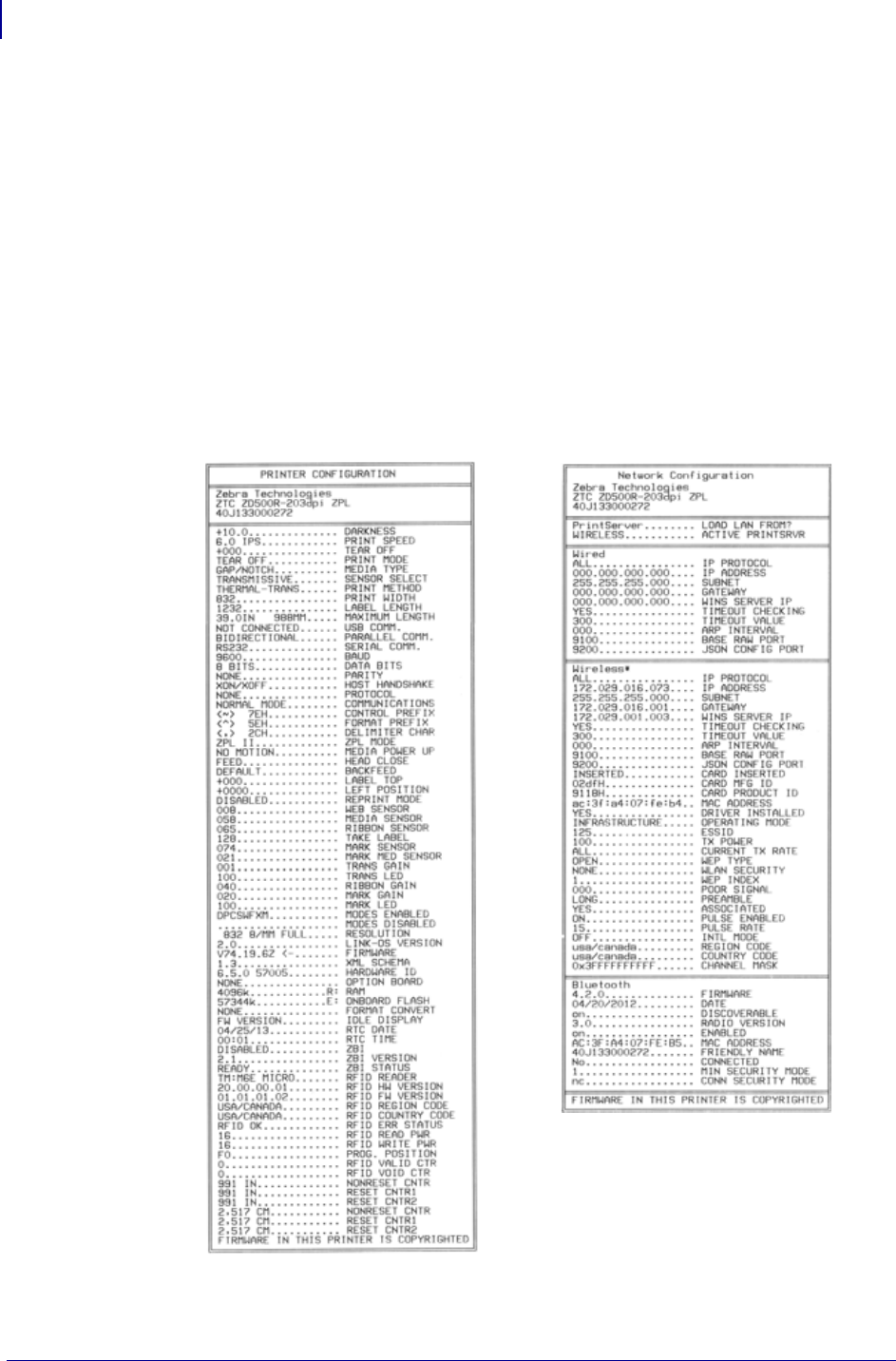
Troubleshooting
Printer Diagnostics
134
P1062653-002 Rev. A ZD500 Series™ Thermal Transfer Printer User’s Guide 1/16/2014
Configuration Report
The Configuration Report (CANCEL self test) prints a set of printer and network
configuration reports.
To perform the configuration, complete these steps:
1. Make sure the media is properly loaded and the top cover of the printer is closed.
2. Press and hold CANCEL button while setting the printer power switch to on (I).
3. Hold CANCEL button down until the printer status light turns green for the first time and
release.
4. The Printer and Network Configuration Reports (below) will be printed a couple of
seconds after printer’s display reports ‘PRINTER READY’.

135
Troubleshooting
Printer Diagnostics
1/16/2014 ZD500 Series™ Thermal Transfer Printer User’s Guide P1062653-002 Rev. A
Print Quality Report
Different types of media may require different darkness settings. This section contains a
simple but effective method for determining the ideal darkness for printing bar codes that are
within specifications.
During the Print Quality Report (FEED self test), a series of labels are printed at different
darkness settings at two different print speeds. The relative darkness and the print speed are
printed on each label. The bar codes on these labels may be ANSI-graded to check print
quality.
During this test, one set of labels is printed at 2 ips, and another set is printed at 6 ips. The
darkness value starts at three settings lower than the printer’s current darkness value (relative
darkness of –3) and increase until the darkness is three settings higher than the current
darkness value (relative darkness of +3).
The speed at which labels are printed during this print quality test depends on the dot density
of the printhead.
• 300 dpi printers: 7 labels are printed at the 2 ips and 6 ips print speeds.
• 203 dpi printers: 7 labels are printed at the 2 ips and 6 ips print speeds.
To perform a Print Quality Report, complete these steps:
1. Print a configuration label to show the printer’s current settings.
2. Turn off (O) the printer.
3. Press and hold FEED while turning on (I) the printer. Hold FEED until the first control
panel light turns off.
The printer prints a series of labels (Figure 1) at various speeds and at darkness settings
higher and lower than the darkness value shown on the configuration label.
Figure 1 • Print Quality Report
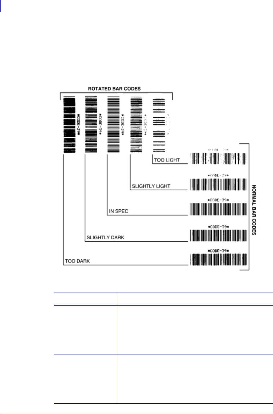
Troubleshooting
Printer Diagnostics
136
P1062653-002 Rev. A ZD500 Series™ Thermal Transfer Printer User’s Guide 1/16/2014
4. See Figure 2 and Table 6. Inspect the test labels and determine which one has the best
print quality for your application. If you have a bar code verifier, use it to measure
bars/spaces and calculate the print contrast. If you do not have a bar code verifier, use your
eyes or the system scanner to choose the optimal darkness setting based on the labels
printed in this self test.
Figure 2 • Bar Code Darkness Comparison
Table 6 • Judging Bar Code Quality
Print Quality Description
Too dark Labels that are too dark are fairly obvious. They may be
readable but not “in-spec.”
•The normal bar code bars increase in size.
•The openings in small alphanumeric characters may fill in
with ink.
•Rotated bar code bars and spaces run together.
Slightly dark Slightly dark labels are not as obvious.
•The normal bar code will be “in-spec.”
•Small character alpha numerics will be bold and could be
slightly filled in.
•The rotated bar code spaces are small when compared to
the “in-spec” code, possibly making the code unreadable.

137
Troubleshooting
Printer Diagnostics
1/16/2014 ZD500 Series™ Thermal Transfer Printer User’s Guide P1062653-002 Rev. A
5. Note the relative darkness value and the print speed printed on the best test label.
6. Add or subtract the relative darkness value from the darkness value specified on the
configuration label. The resulting numeric value is the best darkness value for that specific
label/ribbon combination and print speed.
7. If necessary, change the darkness value to the darkness value on the best test label.
8. If necessary, change the print speed to the same speed as on the best test label.
“In-spec” The “in-spec” bar code can only be confirmed by a verifier,
but it should exhibit some visible characteristics.
•The normal bar code will have complete, even bars and
clear, distinct spaces.
•The rotated bar code will have complete, even bars and
clear, distinct spaces. Although it may not look as good as
a slightly dark bar code, the bar code will be “in-spec.”
•In both normal and rotated styles, small alphanumeric
characters look complete.
Slightly light Slightly light labels are, in some cases, preferred to slightly
dark ones for “in-spec” bar codes.
•Both normal and rotated bar codes will be in spec, but
small alphanumeric characters may not be complete.
Too light Labels that are too light are obvious.
•Both normal and rotated bar codes have incomplete bars
and spaces.
•Small alphanumeric characters are unreadable.
Table 6 • Judging Bar Code Quality (Continued)
Print Quality Description

Troubleshooting
Printer Diagnostics
138
P1062653-002 Rev. A ZD500 Series™ Thermal Transfer Printer User’s Guide 1/16/2014
Reset Printer Factory Defaults
Performing this resets the printer configuration to the factory default values for the non-
network printer settings. Perform a sensor calibration after this procedure. (See Manual
Calibration - Media on page 75.)
To perform a Reset Printer Factory Defaults procedure (FEED + PAUSE Self
Test), complete these steps:
1. Turn off (O) the printer.
2. Press and hold FEED + PAUSE while turning on (I) the printer.
3. Hold FEED + PAUSE until the first control panel light turns off.
The printer configuration is reset to the factory default values. No labels print at the end of
this test.
Reset Network Factory Defaults
Performing this procedure resets the network configuration settings only to the factory default
values.
To perform a Reset Network Factory Defaults procedure (CANCEL + PAUSE Self
Test), complete these steps:
1. Turn off (O) the printer.
2. Press and hold CANCEL + PAUSE while turning on (I) the printer.
3. Hold CANCEL + PAUSE until the first control panel light turns off.
The printer’s network configuration is reset to the factory default values. No labels print at
the end of this test.
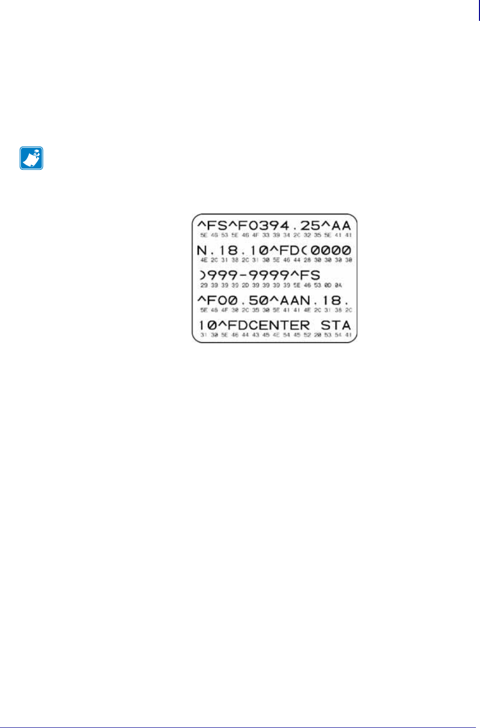
139
Troubleshooting
Printer Diagnostics
1/16/2014 ZD500 Series™ Thermal Transfer Printer User’s Guide P1062653-002 Rev. A
Communication Diagnostics Test
The communication diagnostics test is a troubleshooting tool for checking the interconnection
between the printer and the host computer. When the printer is in diagnostics mode, it prints all
data received from the host computer as straight ASCII characters with the hex values below
the ASCII text. The printer prints all characters received, including control codes such as CR
(carriage return). Figure 3 shows a typical test label from this test.
Figure 3 • Communications Diagnostics Test Label
To use communications diagnostics mode, complete these steps:
1. Set the print width equal to or less than the label width being used for the test.
2. Set the DIAGNOSTICS MODE option to ENABLED. See the User Guide for methods for
changing this setting.
The printer enters diagnostics mode and prints any data received from the host computer
on a test label
3. Check the test label for error codes. For any errors, check that your communication
parameters are correct.
Errors show on the test label as follows:
•FE indicates a framing error.
•OE indicates an overrun error.
•PE indicates a parity error.
•NE indicates noise.
4. Turn the printer off (O) and then back on (I) to exit this self test and return to normal
operation.
Note • The test label prints upside-down.
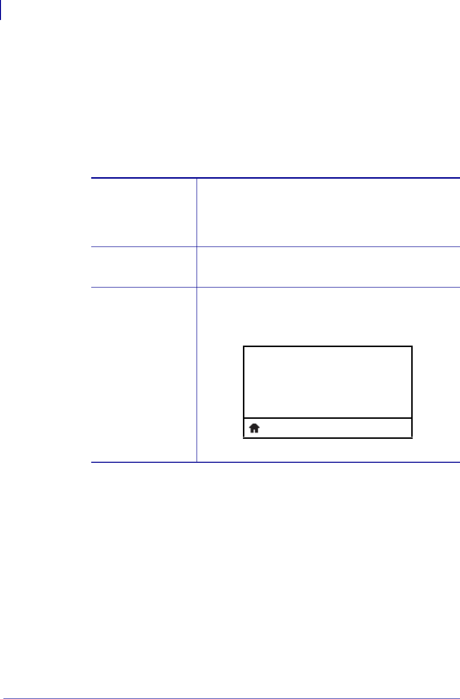
Troubleshooting
Printer Diagnostics
140
P1062653-002 Rev. A ZD500 Series™ Thermal Transfer Printer User’s Guide 1/16/2014
Sensor Profile
Use the sensor profile image (which will extend across several actual labels or tags) to
troubleshoot the following situations:
• The printer experiences difficulty in determining gaps (web) between labels.
• The printer incorrectly identifies preprinted areas on a label as gaps (web).
• The printer cannot detect ribbon.
With the printer in the Ready state, print a sensor profile in one of these ways:
Compare your results to the examples shown in this section. If the sensitivity of the sensors
must be adjusted, calibrate the printer (see Manual Calibration - Media on page 75).
Using the buttons on
the control panel
a. Turn off (O) the printer.
b. Press and hold FEED + CANCEL while turning on (I) the
printer.
c. Hold FEED + CANCEL until the first control panel light
turns off.
Using ZPL a. Send the ~JG command to the printer. See the Zebra
Programming Guide for more information about this
command.
Using the printer’s
control panel.
See TOOLS Menu
on page 56 - PRINT
INFORMATION
a. On the control panel display, navigate to the following
item under the SENSORS menu. See the User Guide for
information about using the control panel and accessing
the menus.
a. Press RIGHT SELECT to select PRINT.
PRINT INFORMATION
SENSOR PROFILE
PRINT
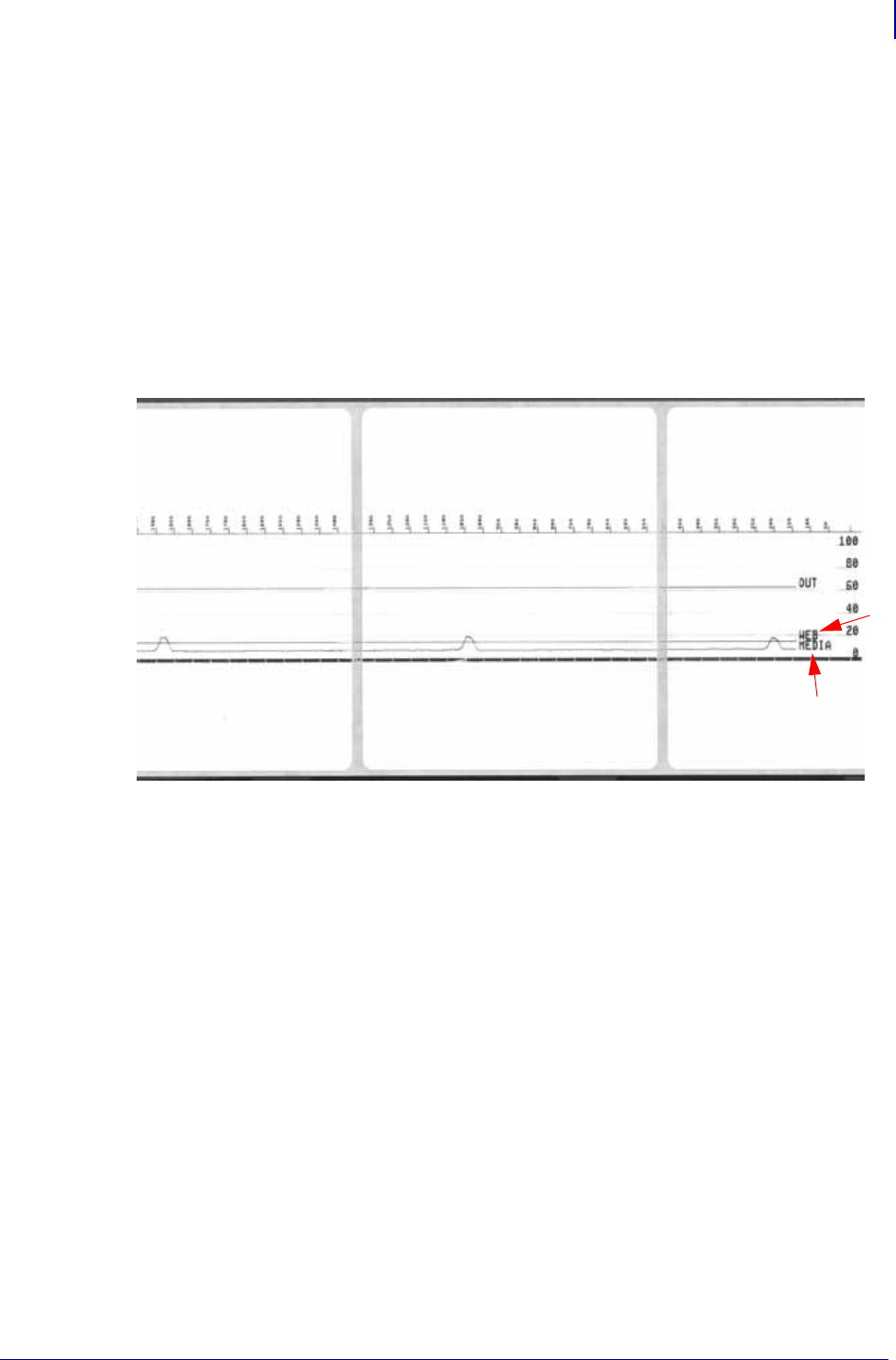
141
Troubleshooting
Printer Diagnostics
1/16/2014 ZD500 Series™ Thermal Transfer Printer User’s Guide P1062653-002 Rev. A
Media Sensor Profile (Figure 4) The line labeled MEDIA (1) on the sensor profile
indicates the media sensor readings. The media sensor threshold settings is indicated by WEB
(2). The media out threshold is indicated by OUT (3).The upward spikes (4) indicate gaps
between labels (the web), the lines between the spikes (5) indicate where labels are located,
and the numbered line at the top (6) provides measurement in dots from the start of the
printout.
If you compare the sensor profile printout to a length of your media, the spikes should be the
same distance apart as the gaps on the media. If the distances are not the same, the printer may
be having difficulty determining where the gaps are located.
Figure 4 • Sensor Profile (Media Section)
1
2
3
4
6
4
5
4
5

Troubleshooting
Printer Diagnostics
142
P1062653-002 Rev. A ZD500 Series™ Thermal Transfer Printer User’s Guide 1/16/2014
Notes • ___________________________________________________________________
__________________________________________________________________________
__________________________________________________________________________
__________________________________________________________________________
__________________________________________________________________________
__________________________________________________________________________
__________________________________________________________________________
__________________________________________________________________________
__________________________________________________________________________
__________________________________________________________________________

1/16/2014 ZD500 Series™ Thermal Transfer Printer User’s Guide P1062653-002 Rev. A
A
Appendix: Interface Wiring
This section provides wiring diagrams for typical interface cables that do not have
a single standardized configuration.
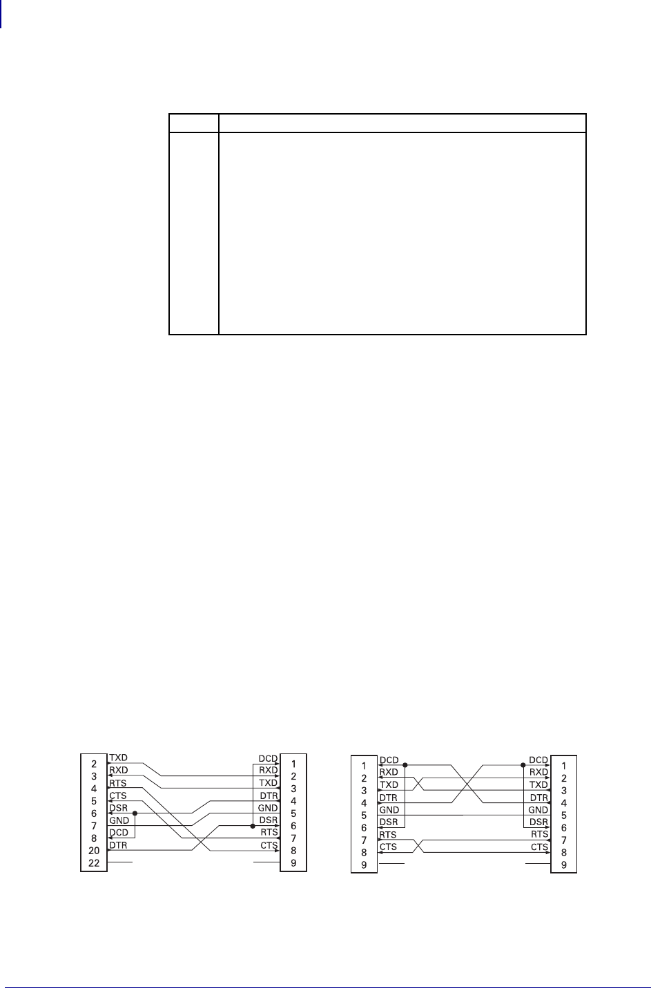
Appendix: Interface Wiring
Serial Port Interface
144
P1062653-002 Rev. A ZD500 Series™ Thermal Transfer Printer User’s Guide 1/16/2014
Serial Port Interface
The maximum current available through the serial and/or parallel port is not to
exceed a total of 0.75 Amps.
When XON/XOFF handshaking is selected, data flow is controlled by the ASCII
control codes DC1 (XON) and DC3 (XOFF). The DTR control lead will have no
effect.
Interconnecting to DTE Devices — The printer is configured as data terminal
equipment (DTE). To connect the printer to other DTE devices (such as the serial
port of a personal computer), use an RS-232 null modem (crossover) cable. Figure
31 shows the required cable connections.
Connecting to the KDU (Keyboard Display Unit) — The original KDU was
designed for DCE printer connections and requires a Zebra custom serial port
gender changing adapter. The KDU now includes the KDU adapter and the Zebra
kit part number for the KDU Adapter is 105934-088. The ZKDU and KDU Plus
both automatically detect the interface
Connecting the Printer to a DTE Device
Pin Description
1 Not used
2 RXD (receive data) input to the printer
3 TXD (transmit data) output from the printer
4 DTR (data terminal ready) output from the printer -- controls
when the host may send data
5 Chassis ground
6 DSR (data set ready) input to the printer
7 RTS (request to send) output from the printer -- always in the
ACTIVE condition when the printer is turned on
8 CTS (clear to send) - Not used by the printer
9 +5 V @ 0.75 A - fused
DB-25S
Connector
to DTE Device (PC)
DB-9P
Connector
to Printer
DB-9P
Connector
to Printer
DB-9S
Connector
to DTE Device (PC)

1/16/2014 ZD500 Series™ Thermal Transfer Printer User’s Guide P1062653-002 Rev. A
B
Appendix: Dimensions
This section provides external printer dimensions.
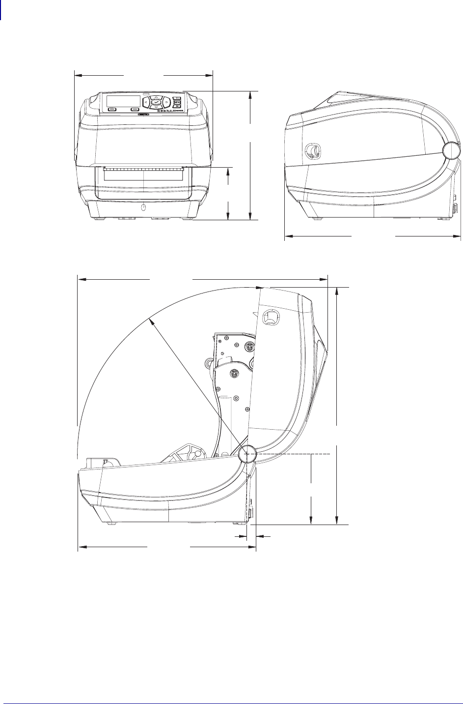
Appendix: Dimensions
External ZD500 Series™ Printer Dimensions
146
P1062653-002 Rev. A ZD500 Series™ Thermal Transfer Printer User’s Guide 1/16/2014
External ZD500 Series™ Printer Dimensions
7.90 in
200.7 mm
7.48 in
190 mm
2.46 in
62.5 mm
10.05 in
255.1 mm
4.05 in
103 mm
0.52 in
13.2 mm
9.53 in
242 mm
13.6 in
345 mm
10.05 in
255.1 mm
14.02 in
356 mm
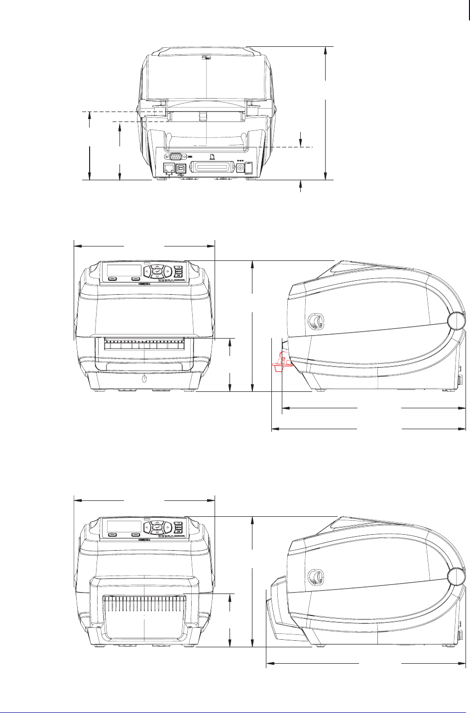
147
Appendix: Dimensions
External ZD500 Series™ Printer Dimensions
1/16/2014 ZD500 Series™ Thermal Transfer Printer User’s Guide P1062653-002 Rev. A
Label Dispenser
Cutter
1.84 in
46.8 mm
3.27 in
83 mm
3.82 in
97 mm
7.48 in
190 mm
10.96 in
278.3 mm
7.90 in
200.7 mm
7.48 in
190 mm
3.1 in
78.5 mm
10.35 in
262.5 mm
11.20 in
284.6 mm
7.90 in
200.7 mm
7.48 in
190 mm
2.91 in
74 mm

Appendix: Dimensions
External ZD500 Series™ Printer Dimensions
148
P1062653-002 Rev. A ZD500 Series™ Thermal Transfer Printer User’s Guide 1/16/2014
Notes • ___________________________________________________________________
__________________________________________________________________________
__________________________________________________________________________
__________________________________________________________________________
__________________________________________________________________________
__________________________________________________________________________
__________________________________________________________________________
__________________________________________________________________________
__________________________________________________________________________
__________________________________________________________________________
