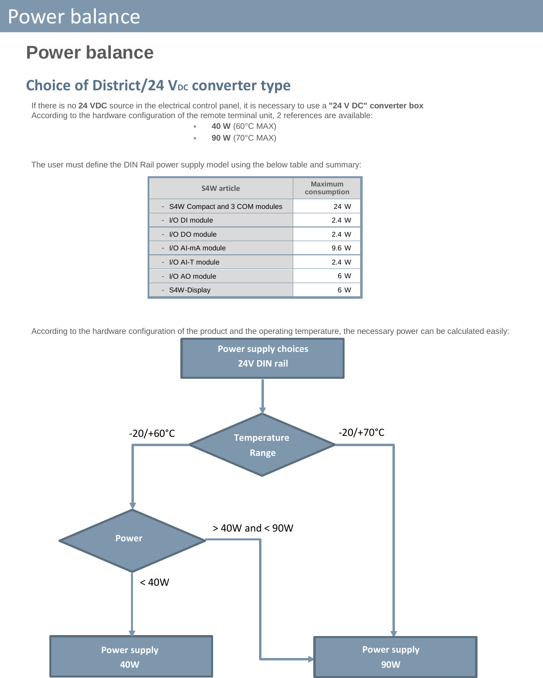
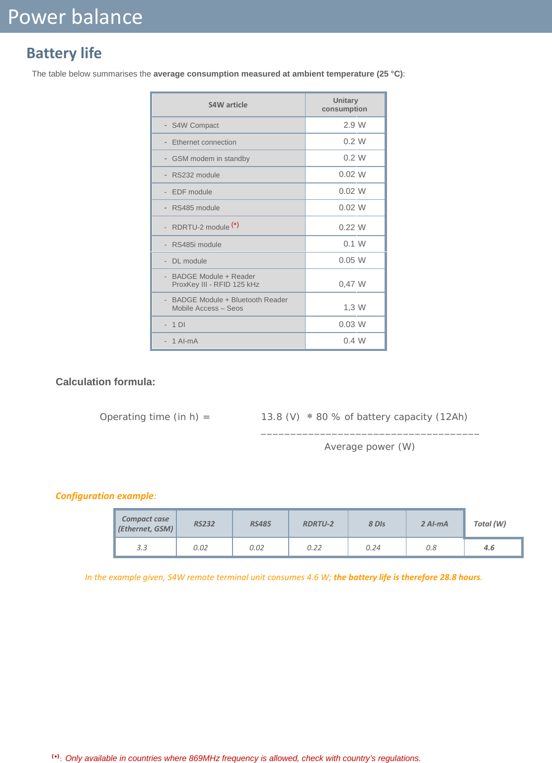
Lacroix Sofrel S4X Remote terminal unit User Manual Sofrel S4W Installation

Lacroix Sofrel Remote terminal unit Sofrel S4W Installation

User Manual

 Jun.-18  Sofrel S4W – Installation                   Warning: This device complies with Part 15 of the FCC Rules. Operation is subject to the following two conditions: (1) this device may not cause harmful interference,  and  (2) this device must accept any interference received, including interference that may cause undesired operation.   The S4W contains a 2G/3G module certified under FCC ID: N7NHL8548. This equipment complies with the FCC RF radiation exposure limits set forth for an uncontrolled environment. This equipment should be installed and operated with a minimum distance of 20cm between the radiator and any part of your body.  This device was tested and found to comply with the limits of Class A digital devices, pursuant to Part 15 of the FCC Rules. These limits are designed to provide reasonable protection against harmful interference when the device is used in a commercial environment. This device generates, uses and can emit radiofrequency energy and, if not installed and used following the instruction manual, can cause harmful interference to radio communications. Operating this device in a residential zone is likely to cause harmful interference, in which case the user will be held responsible for correcting the interference at his/her own expense.  Any modification made to this device that has not been explicitly approved by LACROIX Sofrel may cause harmful interference and voids the FCC authorisation to use this device.   All rights reserved It is strictly forbidden to reproduce all or part of this manual or to distribute it in any form whatsoever, without the prior authorisation of LACROIX Sofrel. The information contained in this manual has been carefully checked and is deemed to be correct. However, LACROIX Sofrel cannot be held responsible for any errors or inaccuracies that may exist in this manual, nor for any resulting direct or indirect damage, even if it has been informed of the possibility of such damage. Due to ongoing product development, LACROIX Sofrel reserves the right to make any modifications to this manual and to related products at any time, with no prior notification to concerned individuals.
Case - Features   Case - Features Description  S4W comes standard in a compact case and includes the following: • DC power supply: • 1 24 V DC Power supply block (with backup battery) • I/O: • Input/output terminals for connecting: 16 DI, 4 AI (4-20 mA) and 4 DO • Com: • 2 integrated communication interfaces: 2G/3G GSM and 100 Mbit/s Ethernet networks • Ports: • 1 USB service port on front-face (for connecting S4W-Tools configuration PC) • 1 Ethernet port • 1 USB operational port USB (for connecting the S4-Display) • Indicators: • 3 indicators: Power supply (on), IP network (on), Generation Operation (off) • Slots: • For 1-3 additional communication modules • Temperature:  • Ambient operating temperature range: -20- +70°C (storage range: -40- +85°C)    • L =  195 mm • H =  125 mm • W =  63 mm (+ 7 or 15 mm, depending on the DIN rail) • M =  700 g (weight of the compact case with 3 COM modules) Expansion capacities For configurations requiring additional resources, the case can be equipped with the following add-ons: • I/O: Up to 10 input-output expansion modules from among the following types: 16DI / 8AIT / 8AIMA / 4DO / 8DO / 8AOAV  • Com: Up to 3 communication modules: RS232 / RS485 / RS485-i / DL / EDF / BADGE and RDRTU-2 Radio link external modem (869 MHz without licence) connected via a RS485 module  (∗) • Mem: 1 slot for a micro SD memory card (for later usage) Up to 3 additional COM  modules Expansion via snap-in  I/O modules L    H  D     M (∗): Only available in countries where 869MHz frequency is allowed, check with country’s regulations.
Case - Mounting   Case - Mounting The SCADA Central Station must be installed by qualified personnel in accordance with local regulations (NF C 15-100 in France, NEC in the U.S., etc.) The case must be installed in a fire-resistant enclosure. This enclosure must stay closed during normal operation; it is only accessible by qualified personnel and requires a key or tool to open it. The case is mounted on a standard metal DIN rail (35 mm).  The DIN rail is required to be connected to Ground; the grounding connection is carried out automatically when the case is mounted.  To remove the case from the DIN rail, the user will use a screwdriver-type tool.  If the fasteners become unfastened, the user must make sure to replace them to prevent the case from tipping (this note also applies to each I/O expansion module).    Rear view of the case  I/O expansion modules             and               Compact case    Cable sections Access Cable Min. section mm² / AWG Max. section mm² / AWG Inputs / Outputs single-core cable 0.14 / 26 1.5 / 16 stranded cable without tip 0.14 / 26 1.5 / 16 multi-strand with insulated tip DIN 46228 T4 0.14 / 26 1.0 / 17 multi-strand with non-insulated end DIN 46228 T1 0.14 / 26 1.5 / 16 Power and Battery monofilament 0.75 / 18 1.5 / 16  multi-strand without tip 0.75 / 18 1.5 / 16  multi-strand with mouthpiece DIN 46228 T4 0.75 / 18 1.0 / 17  multi-strand with non-insulated end DIN 46228 T1 0.75 / 18 1.5 / 16  With multi-strand cable: use crimping ferrules type DIN 46228 T4 or DIN 46228 T1. For the battery, use Faston crimp lugs 6.35 mm female type insulated red.  Automatic locking on DIN rail Automatic ground terminals 35 mm DIN
Case – Power supply   Case – Power supply The Compact case provides power for itself, as well for the COM modules (including the RDRTU-2 modem connected to the RS485 module) (∗). The entire unit is compatible with a 24 VDC (± 20%) supply voltage and is protected against reverse polarity. The 24 VDC power supply must be TBTS/ES1.  Power connector For the power supply, use a 0,75 mm² cross-sectional ∅ minimum.  5A fuse: Installation of a fuse is recommended on the Battery input.  • +  or Battery Input • –  or Battery Ground • +24 VDC • 0V or GND If there is no 24 VDC source in the electrical control panel, it is necessary to use a "24 VDC" converter box According to the RTU hardware configuration, 2 references are available (refer to the power balance table):   • 40 W (60°C MAX) • 90 W (70°C MAX)  The device's isolating mechanism is the ‘24 VDC + backup battery’ power connector. Switch the case and the I/O modules off before removing or adding COM modules.  Powering the I/O modules The I/O modules have a separate 24 Vdc power supply, independent of the compact case: it is not backed up by the battery.  Simply connect a single I/O module to a 24 VDC power source (according to the power balance); this power source automatically propagates to other installed modules.  The device's isolating mechanism is the ‘24 VDC’ power connector. Switch the case off before removing or adding I/O modules.  Backup battery The power supply to the case can be backed up with a 12 VDC lead battery, either 4 Ah or 12 Ah.  A periodic battery capacity test is performed automatically. The RTU manages the charge and performs continuous self-testing of the external battery: • Protection against overloads • Automatic shut-off in the event of a short-circuit  • Protection against reverse polarity. • Battery detection. • Protection against deep discharges (threshold at 10.2 V).  When powering via backup battery, the voltage must be at least 12 V ±200 mV to start up;  When the product has started, its operating range is between 10.2 V and 13.8 V. Furthermore, when the RTU power supply is voluntarily cut off for a long period (typically 48 hours or more), it is necessary to disconnect the battery to prevent deep discharge and premature wear. Powering via solar panels 24V solar panel controllers are connected directly to the GND and +24 VDC terminals.  Use of SunSaver controllers is recommended: contact our technical sales department to ensure selection of the appropriate controller type (6, 10 or 20) and sizing of the solar panel according to the geographic location of installation. Make sure to follow the recommended installation indicated in the manual provided with the controller: assembly in vertical position, execution of the connections in ascending order of the terminal strips 1 to  6 on the diagram opposite (battery, solar panel, then the RTU last), position of the jumper for the use of an open battery, etc.     24 V panel A 24 V battery or 2 X 12 V batteries (in series) 3A fuse (∗): Only available in countries where 869MHz frequency is allowed, check with country’s regulations.
Case - Inputs/Outputs   Case - Inputs/Outputs Connection of DIs  Example for 2 DIs:           Technical specifications -  Number of digital inputs: 16   -  Contact type: Dry self-powered contact: Normally open/ closed  (configurable positioning logic) -  Maximum length of cable: 1,000 metres (AWG24 SYT+ cable type) It is necessary to relay the digital inputs if the cable length is any higher   or if the cable crosses an environment with high interference. -  Digital input filtering: Any steady state digital input can be used for the counter acquisition;  the minimum duration of the steady state is 2 ms (max frequency = 250 Hz) -  Isolation: The DIs are isolated from the rest of the electronics; the isolation voltage  is 3000 VDC minimum. The DIs are not isolated from each other.      Cable for  digital inputs 1 pair  for digital input no. 1  1 pair  for digital input no. 2 DI terminal strip: Possible applications: Pulse counters Duration counters Digital input loop: Normally closed Digital input loop: Normally open  1 shared for 4 digital inputs
Case - Inputs/Outputs   Connection of AIs (4-20mA)  Only sensors with floating output delivering a current source free from any reference with respect to Ground and, in all cases, several sources having no common point between them, are directly compatible with our materials.  Otherwise, the installer must provide a galvanic isolation device in the ‘RTU – Sensor’ link.  Installation of surge arresters:  All SOFREL sensors come with inbuilt surge protection. However, if the ‘RTU – Sensor’ link cable runs outside of building or extends a significant length (> 200 metres), a 4-20 mA surge arrester should be installed on the RTU side.    Example for 2 AIs, ‘4-20 mA’:     Technical specifications -  Number of ANA inputs:  4 in measuring current 4-20 mA   -  Type: -  Precision: 0.1% (25°C) -  Resolution: 16 bits  -  Remote power feeding: -  2 sensors per remote power feed -  Voltage = 16V ± 10 % -  Protection current = 50 mA (maximum for 1 or 2 inputs) -  Input impedance: -  100 Ω      S4W AI 4-20mA cable Sensor       Wiring a surge arrester  AI terminal strip: 1 pair for ANA input no.1 (Case for remotely powered sensor) 1 pair for ANA input no. 2 (Case for autonomous sensor) 1 pair  for ANA input no. 1 1 pair  for ANA input no. 2 Sensor, 4-20 mA
Case - Inputs/Outputs   Connection of DOs DOs are 12 V / 24 V AC/DC ’very low voltage’ voltage-relay type digital outputs: they are compatible with 24 V relays and control panel indicator lights. By default, and following a total power cut (24V and Battery), DOs are in their 'open' state (idle state = 0). In case of product reinitialisation, the state of each DO is retained (no forced return to the idle state).  The user defines the ‘bistable’ or ‘impulse’ control type when configuring each DO data point. When a DO is configured to control the ‘Watchdog safety’ feature; this output is reinitialised according to inverse logic (the output is in the closed state if no default; it switches to the open state if a default is present). This 'Watchdog' output is very useful for controlling power supply and for the proper functioning of the RTU (see § ‘Data processing – Operational safety’).   The DO do not allow direct control of power units.   Example of control of 2 DC relays by 2 DO:      Technical specifications  -  Number of DO:  -  4 in alternating current (AC) and/or direct current (DC) -  Output type: -  free from all potential -  Maximum switching voltage:  -  24 V AC/DC +20% (40 V peak) -  Continuous current: -  150 mA -  Isolation: -  1500 VRMS between the DO and the control case    1 pair for the DO no.1 1 pair for the DO no.2 DC relay        DC relay DO terminal strip:
Case – Indicator lights and USB ports   Case – Indicator lights and USB ports 3 indicator lights display the operating status of the RTU:     GREEN • Case power supply (light on if OK)  WHITE • Communication with the Centralised System (light on if connection OK)  RED • General system operation (light off if OK)   On the front-face, the USB port, type B (printer), connects to the configuration PC.    UNDER THE CASE, the second USB port connects to the S4 Display.  S4-Display connection The S4 Display must be flush mounted and facing forward in the control panel.   • Dimensions: • Front part = 170.4 × 106.8 × 7.5 mm  • Depth of the rear part = 41.7 mm • Dimensions of the flush-mounting area = 160.7 x 93 mm • Maximum thickness of the receiving panel = 5.5 mm       • Rear view: • Connection of 24V and LAN TERMINAL STRIPS    Black    Red  Prepare a free space of 100 mm around the display (above, below, behind), 50 mm on the sides.  Cable length = 2 metres Ethernet USB adapter 2 m Ethernet cable
Case - Ethernet Connection   Case - Ethernet Connection The RTU connects to the Ethernet network via the RJ45 connector accessible underneath the case.     Ethernet network connector (LAN):  It is possible to connect either a straight-through or crossover cable.   2 lights underneath the case indicate the network connection status: Indicator On Off blinking -  Yellow Active Ethernet link Inactive Ethernet link Transmitting and/or receiving data -  Green 100 Mb/s network speed 10 Mb/s network speed or isolated line
Case - GSM Connection   Case - GSM Connection The compact case comes standard with a 2G/3G-compatible GSM modem: the RTU thereby communicates in GSM-IP with its recipients (SCADA Central Station, Inter-RTU with other remote units, PC S4W-Tools, Email recipient) and in SMS.  Operation Communications Frequency Bands (in MHz) -  3G UMTS/HSDPA B1 = 2100, B2 = 1900, B5 = 850, B6 = 800, B8 = 900, B19 = 800 -  2G GSM/GPRS/EDGE B3 = 1800, B5 = 850, B8 = 900, B25 = 1900 The 2G/3G modem does not provide any insulation; the antenna must therefore be put inside the building where the S4W is installed. Otherwise, make sure to use an appropriate isolation device.  The GSM external antenna is the ‘Penta-band’ type (2G/3G compatible). The SMA female connector is used to connect the ’0 dB’ ¼-wave GSM antenna.  (Tightening torque: 0.4 Nm max).           Make sure the RTU is switched off before inserting the SIM card.   Accessing the micro SIM card Inserting and removing the micro SIM card is done on the left side of the case, by pressing on the bottom of the connector with the contacts facing the rear of the case, until there is a locking click. To insert the micro SIM card, open the flap on the left side of the case: this action does not require removing any communication modules or disconnecting any I/O cables.  The bracket allows the antenna to be mounted vertically on a metal ground plane: This metal plane is necessary only when a ¼-wave GSM antenna is used. 4-metre GSM antenna cable Micro SIM MicroSD
I/O Expansion modules   I/O Expansion modules The RTU can be equipped with I/O expansion modules (10 modules max.) to expand its input-output capabilities.  The types of available I/O modules are:  • 16DI • 8DO • 8AI-mA • 8AI-T° • 8AO      Powering the I/O modules The I/O modules have a separate 24 Vdc power supply, independent of the compact case; this power supply is not backed up by the battery.  A single I/O module must be powered by a minimum 500 mA source; this power source automatically propagates to other installed modules. The green LED indicates that the supply voltage is present; the module type and its physical location are automatically detected by the software.    Switch the case and the I/O modules off before removing or adding I/O modules.   Mounting Each module snaps in easily on the right side of the case and must be mounted on the DIN rail (I/O modules cannot be remotely deported from the main case).    The DIN rail must be connected to Ground; the Ground terminal connection is carried out by mounting the casing. If the fasteners on the DIN rail become unfastened, the user must make sure to replace them to prevent the module from tipping over.   Handling 1°/ Use the screwdriver to turn the bolt that attaches the module to the DIN rail, 2°/ Press the button on the front side to disengage the expansion module from the main panel or from another module.   Example case with 2 I/O modules L =20.5 mm wide Disconnect button for each module. Mounting bolt on the DIN rail.
16 DI Expansion Module   16 DI Expansion Module Connection of DIs Example for 2 DIs:       Technical specifications -  Number of digital inputs: 16  -  Dry self-powered contacts: -  Normally open/Normally closed  (Configurable positioning logic) -  Maximum length of cable: -  1,000 metres (AWG24 SYT+ cable type) It is necessary to relay the digital inputs if the cable length is any higher   or if the cable crosses an environment with high interference. -  Digital input filtering for counters: Any steady state digital input can be used for the counter acquisition; the minimum duration of the steady state is 2 ms (max frequency is 250 Hz) -  Bias voltage: the max bias voltage on a DI is 15 V. -  Insulation: the DIs are isolated from the rest of the I/O module electronics; the insulation voltage is 3000 VDC minimum.  The DIs are not isolated from each other.           1 pair  for digital input no.2  1 pair  for digital input no.1  1 shared for 4 digital inputs +24 VDC 0V or GND Possible applications: Pulse counters Duration counters Digital input loop: Normally closed Digital input loop: Normally open
8AI-mA Expansion Module   8AI-mA Expansion Module Connection of AIs (4-20mA)  This type of AI is a ‘4-20mA Current’ measurement input. Only sensors delivering a current source free from any reference with respect to Ground and, in all cases, several sources having no common point between them, are directly compatible with our materials (‘floating’ output).  Otherwise, the installer must provide a galvanic isolation device in the ‘RTU – Sensor’ link.  Installation of surge arresters:  All SOFREL sensors come with inbuilt surge protection. However, if the ‘RTU – Sensor’ link cable runs outside of building or extends a significant length (> 200 metres), a 4-20 mA surge arrester should be installed on the RTU side.    Example for 2 AIs, ‘4-20mA’:    Technical specifications -  8 ANA inputs -  4-20 mA current measurement -  Precision: 0.1% (25°C) -  Resolution: 16 bits  -  Remote power feed -  2 sensors per remote power feed -  Voltage: VEXT -2V  (VEXT = 24 VDC power feed) -  Protection current = 50 mA (shared protection for 2 inputs) -  Input impedance: -  100 Ω   I/O Module  AI 4-20mA cable Sensor Wiring a surge arrester   (Case for autonomous sensor)  (Case for remotely powered sensor) 1 pair for ANA input no.1  1 pair for ANA input no.2  Sensor, 4-20 mA
8AI-T Expansion module   8AI-T Expansion module Connection of AI (Temperature) modules  The ‘AI-T’ modules interface with the following temperature probes: • Pt 1000 type DIN43760 (IEC60751) • Ni 1000 type TCR5000 (Siemens probes) • Ni 1000 type DIN43760 (IEC60751)  Example for 2 AIs, ‘4-20mA’:     Technical specifications -  8 ANA inputs -  Temperature measurement -  Precision: from ±0.3% to ±0.4% according to the probe type -  Resolution: 16 bits  -  Types of compatible probes:  • CRIMP  TYPE STANDARD T RANGE  PRECISION • Pt 1000 DIN43760 (IEC60751) between -50°C and +400°C ±0.3% (±1.35°C) at 25°C • Ni 1000 TCR5000 (Siemens probes) between -50°C and +150°C ±0.4% (±0.8°C) at 25°C • Ni 1000 DIN43760 (IEC60751) between -50°C and +150°C ±0.4% (±0.8°C) at 25°C   1 pair for ANA input no.1 1 pair for ANA input no.2 1 pair for ANA input no.1  1 pair for ANA input no.2  Temperature Probes
4DO or 8DO Expansion module   4DO or 8DO Expansion module Connection of DOs One 12V / 24V AC/DC ’very low voltage’ voltage-relay type digital outputs: the DOs are compatible with 24 V relays and electrical cabinet indicator lights. By default, and following a total power cut (24 V and Battery), DOs are in their 'open' state (idle state = 0). However, the state of each DO is retained during product reinitialisation.  The user defines the ‘bistable’ or ‘impulse’ control type when configuring each DO data point.  The DO do not allow direct control of power units.   Example of control of 2 DC relays by 2 DO:      Technical specifications  -  4 or 8 digital outputs: -  in alternating current (AC) and/or direct current (DC) -  Maximum switching voltage:  -  24 V AC/DC +20% (40 V peak) -  Continuous current:  -  150 mA -  Isolation:  -  1500 VRMS between the DO and the case   1 pair for the DO no.1 1 pair for the DO no.2 Protection  diode    Protection  diode  DC Relay       DC Relay
8 AO Expansion module   8 AO Expansion module Connection of AOs An AO is an analogue output that generates a ‘0-10 V Voltage’ or ‘0-20 mA Current’ analogue signal. Each AO can be configured in voltage or current (parameter handled by the software). Example for 2 AO:      Technical specifications   ‘Voltage’ AO ‘Current’ AO -  Output range  0-10 V  0-20 mA -  Load impedance on the output Minimum of 400 Ω Maximum of 500 Ω -  Residual ripple Less than ±20 mV   ±40 µA under 500 Ω -  Precision of AO generated  0.3 % over the entire temperature range,  0.25% at 25°C 0.5%, or ±0.1 mA -  Resolution of AO  3600 points (2.8 mV) 3600 points (5.6 µA)  1 pair for the ANA output no.1 1 pair for the ANA output no.2 1 pair  for the ANA output no.1 1 pair  for the ANA output no.2
RS232 communication module   RS232 communication module This module allows the RTU to communicate via RS232 link (with or without control signals) at an adjustable speed  between 300 and 115,200 bits/s. The RS232 module is protected against short circuits, polarity inversion and accidental connection to voltage less than 24 V.   • RTS:  ’Request to Send’ output • :   0V or GND • RX:  ’Data reception’ input • TX:  ’Data transmission’ output • CTS:  ’clear to send’ input  Example of connection:  Technical specifications -  Cable: -  Use a ‘1 pair’ cable , SYT+ AWG24 ∅ = 5/10ths  (100Ω resistance per kilometre) -  Use the twisted pairs of a cable with screen or shielding per pair of conductors. -  Connect the cable shielding to the Ground on one side only. -  Maximum length = 15 metres.  Remote terminal unit MODBUS device (PLC or SCADA Central Station)  RS232 link
RS485 communication module   RS485 communication module This module allows the RTU to communicate via RS485 link with one or several devices connected to equipotential Grounds, as is often the case within a single building. A ‘bus’ network topology is required: no looping or star structure configurations. Any diversions from the main bus must be kept as short as possible (< 10 m). The communication speed on the link is configurable: From 1200 to 115,220 bits per second.    • ⊕:  power supply for Sofrel devices  • :  0V or GND • D+:  RS485 bus potential (+) • D-:   RS485 bus potential (-)   Connecting ⊕ is only useful for supplying power to the RDRTU-2 Radio link modem.   Example of interconnection of several remote terminal units:   Technical specifications -  Cable: -  Use a twisted pair from a wire with screen or shielding. -  Pay attention to polarity. -  Connect the cable shielding to the Ground on one side only. -  Maximum length = 1200 metres (for greater lengths, use repeaters).   RTU RTU   RS485 bus  Remote terminal unit (∗): Only available in countries where 869MHz frequency is allowed, check with country’s regulations. (∗)
RS485i communication module   RS485i communication module This module makes it possible for the RTU to communicate via isolated RS485 link (without power feed) with one or several devices when equipotential grounding is not guaranteed. This can be the case when 2 communicating devices are located in different buildings.  A ‘bus’ network topology is required: no looping or star structure configurations. Any diversions from the main bus must be kept as short as possible (< 10 m). The communication speed on the link is configurable: From 1,200 to 115,220 bits per second.      • :   common • D+:  RS485 bus • D-:  RS485 bus  Example connection of 2 devices:    Technical specifications -  Cable: -  Use a twisted pair from a wire with screen or shielding. -  Pay attention to polarity. -  Maximum length = 1200 metres (for greater lengths, use repeaters).   For significant distances, install a 120 Ohm resistor Ω in parallel with the devices located at the 2 ends of the link (for more information, Contact the STC LACROIX Sofrel technical team).     RTU RS485 surge arresters RTU   RS485 bus
DL communication module:   DL communication module: This module makes it possible for the remote terminal unit to communicate via Private link (in V23/V23R modulation) with one or several devices.     • :   Common • L1:  Private link • L2:  Private link Connection as Private link:  Example Multipoint Link:   Technical specifications -  Cable: -  Use a ‘1 pair’ cable , SYT+ AWG24 ∅ = 5/10ths  (100Ω resistance per kilometre) -  Connect the cable shielding to the Ground on one side only.  - Multipoint: -  A ‘bus’ network topology is required: no looping or star structure configurations. -  The unit can communicate with 20 MODBUS devices maximum, distributed evenly over a maximum distance of 15 km. -  The branches of the Multipoint link must be as short as possible and the 2 devices at the start and end of the link must be configured as ‘Ends of Line’.   LS surge arrester  LP link Maximum bus length = 15 km  (Wiring used: SYT+ AWG24, 0.203 mm² cross-section) End of line  End of line  Node  Node Node Node
EDF communication module   EDF communication module This module makes it possible for the RTU to communicate over a ‘2 wire remote data’ link (ERDF modulation at 1200 baud/50 KHz) for reading data coming from an ERDF meter (BLUE, YELLOW, or GREEN type).     • I1:  ’EDF Remote data’ link • I2:  ’EDF Remote data’ link Example of connection:   Technical specifications -  Cable: -  Use a ‘1 pair’ cable , SYT+ AWG24 ∅ = 5/10ths   -  Maximum distance: 300 metres.  -  Meters: -  Use one EDF module per meter. -  The remote terminal unit can communicate with up to 3 electrical meters of different types: BLUE, YELLOW, or GREEN.    Remote Data Serial Link
RADIO RDRTU-2 communication module   RADIO RDRTU-2 communication module The Remote Terminal Unit permits utilisation of a license-free RDRTU-2 radio modem at 869 MHz (∗).  This modem radio is operable up to 500 mW to communicate with other remote equipment as MODBUS master or slave; the typical range is 5 km (and 10 km maximum). It connects with a RS485 module; no other module should be used to power it.  3 types of HGAs are proposed to optimise transmission (depending on the application and the relief of the terrain.  A high-gain antenna allows better reception and lower transmission power.    Connecting the RDRTU-2 module      Grounding:  coaxial cable provided with the RDRTU-2 module guarantees continuity between the connector chassis and the cable screen. Using a cable longer than 1 metre requires connecting the screen of the coaxial to Ground at both ends of the cable. (∗)          RDRTU-2  Terminal strip    Cable mass Mast to ground connection (∗)    RDRTU-2 housing N Type connector 1 metre 50 metres RS485 Terminal strip (∗): Only available in countries where 869MHz frequency is allowed, check with country’s regulations.
RADIO RDRTU-2 communication module   Technical specifications  (∗) -  Receiver sensitivity: - 118 dBm -  Antenna position: -  Place the antenna as high as possible, in a non-enclosed space (if possible outside of a building), and in an area sufficiently distanced from any other antenna or metallic mass.  -  RDRTU-2 module: -  Mounting bracket: allows the module to be offset at a high point near the antenna to improve the reception level; it can be either screwed onto the antenna mast or attached to a vertical surface. -  For the ‘RDRTU-2 – RS485’ link: Use a ‘2-pair’ cable with a shielded pair (D+,D-) and 1.5 mm² cross-section, with reinforced, flexible and waterproof sheath. -  The maximum length of the cable for offsetting the module is 50 metres.  -  The RDRTU-2 module must not be powered with any other source than the Remote Terminal Unit.  -  Frequency and Power: -  3 configurable frequency channels: • 869.475 MHz • 869.525 MHz • 869.575 MHz  -  4 user-defined transmission powers: • 16 dBm/40 mW • 21 dBm/125 mW • 24 dBm/250 mW • 27 dBm/500 mW  ( ∗)  ( ∗): ‘27 dBm/500 mW’ power is reserved for use with a low-gain antenna. -  Antenna types:   We offer 3 types of high-gain antenna in order to optimise transmission depending on the application and the relief of the terrain (a high-gain antenna enables better reception and lower transmission power):  High-gain antennas Transmission power   +13 dBi/+11 dBd  +8 dBi/+6 dBd   +5 dBi/+3 dBd • 16 dBm • 21 dBm • 24 dBm ( ∗): on some types of antennas, the gain is specified in dBd (dBd = dBi - 2). Terms of use of license-free radio  EN 300 220-1 standard:  • The EN 300 220-1 standard defines a maximum ‘Duty Cycle’ (1)  fixed at 6 minutes per hour and per transmitting device.  • The user must therefore verify that the Inter-RTU Radio link configured on the RDRTU-2  modem complies with this time.  The hourly duty cycle of the RDRTU-2 modem frequency is:  proportional to the number of defined periodic blocks on all communicating devices of the link, with a maximum transmission time of 2.5 sec per block,  proportional to the number of cycles per hour and is a function of the ‘Silence between cycle’ and/or ‘silence between communicating devices’ configurations. In practice, we can evaluate this silence time in seconds as:  'Silence between cycle’ = ‘silence between interlocutors’ = ‘Number of blocks x 25’  In some countries, usage of this frequency range may have restrictions; for more information, please consult your local telecommunications regulatory body. (1) Definition of ‘Duty Cycle’: Purpose of the duty cycle limit is to ensure that no application can occupy a frequency range for more than a certain percentage of time. The duty cycle defines a maximum percentage of time (expressed as a percentage over any period of time that a modem is allowed to transmit). Duty cycle limitation must be controlled by the terminal equipment connected to the modem. Contact LACROIX Sofrel’s Technical Department for your duty cycle calculations.      (∗): Only available in countries where 869MHz frequency is allowed, check with country’s regulations.
BADGE communication module   BADGE communication module S4W allows the use of HID (contactless) badges for the People Identification, "Anti-Intrusion", and "Human Endangered" functions on monitored network sites. The + VDC power supply and pilot LED control are provided by the RTU (includes battery backup).  Connecting the HID reader     Technical characteristics -  Cable :  -  Use a "1 pair" cable type SYT + AWG24 ∅ = 5 / 10th -  Maximum distance: 100 meters.  -  Readers : -  Use a BADGE module per HID reader. -  The RTU can communicate at maximum with 3 readers.        HID badge reader (Wiegand protocol) Maximum length: 100 meters Red / Rouge Black / Noir Green / Vert White / Blanc Orange / Orange
Power balance   Power balance Choice of District/24 VDC converter type If there is no 24 VDC source in the electrical control panel, it is necessary to use a "24 V DC" converter box According to the hardware configuration of the remote terminal unit, 2 references are available:   • 40 W (60°C MAX) • 90 W (70°C MAX)  The user must define the DIN Rail power supply model using the below table and summary: S4W article Maximum  consumption -  S4W Compact and 3 COM modules 24 W -  I/O DI module 2.4 W -  I/O DO module 2.4 W -  I/O AI-mA module 9.6 W -  I/O AI-T module 2.4 W - I/O AO module 6 W -  S4W-Display 6 W   According to the hardware configuration of the product and the operating temperature, the necessary power can be calculated easily:                  Temperature  Range -20/+60°C -20/+70°C Power supply choices 24V DIN rail Power supply 40W > 40W and < 90W < 40W Power supply 90W Power
Power balance   Battery life The table below summarises the average consumption measured at ambient temperature (25 °C): S4W article Unitary consumption  -  S4W Compact 2.9 W -  Ethernet connection 0.2 W -  GSM modem in standby 0.2 W -  RS232 module 0.02 W -  EDF module 0.02 W -  RS485 module 0.02 W -  RDRTU-2 module (∗) 0.22 W -  RS485i module 0.1 W -  DL module 0.05 W -  BADGE Module + Reader ProxKey III - RFID 125 kHz 0,47 W -  BADGE Module + Bluetooth Reader Mobile Access – Seos 1,3 W -  1 DI 0.03 W -  1 AI-mA 0.4 W  Calculation formula:  Operating time (in h) =   13.8 (V)  ∗ 80 % of battery capacity (12Ah)    _____________________________________     Average power (W)   Configuration example:   Compact case (Ethernet, GSM) RS232 RS485 RDRTU-2  8 DIs 2 AI-mA Total (W) 3.3 0.02 0.02 0.22 0.24 0.8 4.6 In the example given, S4W remote terminal unit consumes 4.6 W; the battery life is therefore 28.8 hours.   (∗): Only available in countries where 869MHz frequency is allowed, check with country’s regulations.

Navigation menu