Laerdal Medical AS 20-10494 Resusci QCPR Manikins User Manual LinkLoad Board Design
Laerdal Medical AS Resusci QCPR Manikins LinkLoad Board Design
User Manual
Att 1 to 00054577 rev.B
Resusci Main Board Electronic Design Description Page: 1 of 9
Document number: 00054577
Document revision: B
Document title: Resusci Main Board Radio module Installation instructions
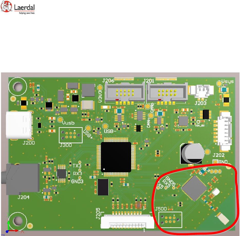
Figure 1. Resusci Main Board. Radio part within red line

Att 1 to 00054577 rev.B
Resusci Main Board Electronic Design Description Page: 2 of 9
Table of Contents
1. Scope ........................................................................................................................................ 3
2. Application ............................................................................................................................... 3
3. Features ................................................................................................................................... 3
4. Abbreviations ........................................................................................................................... 3
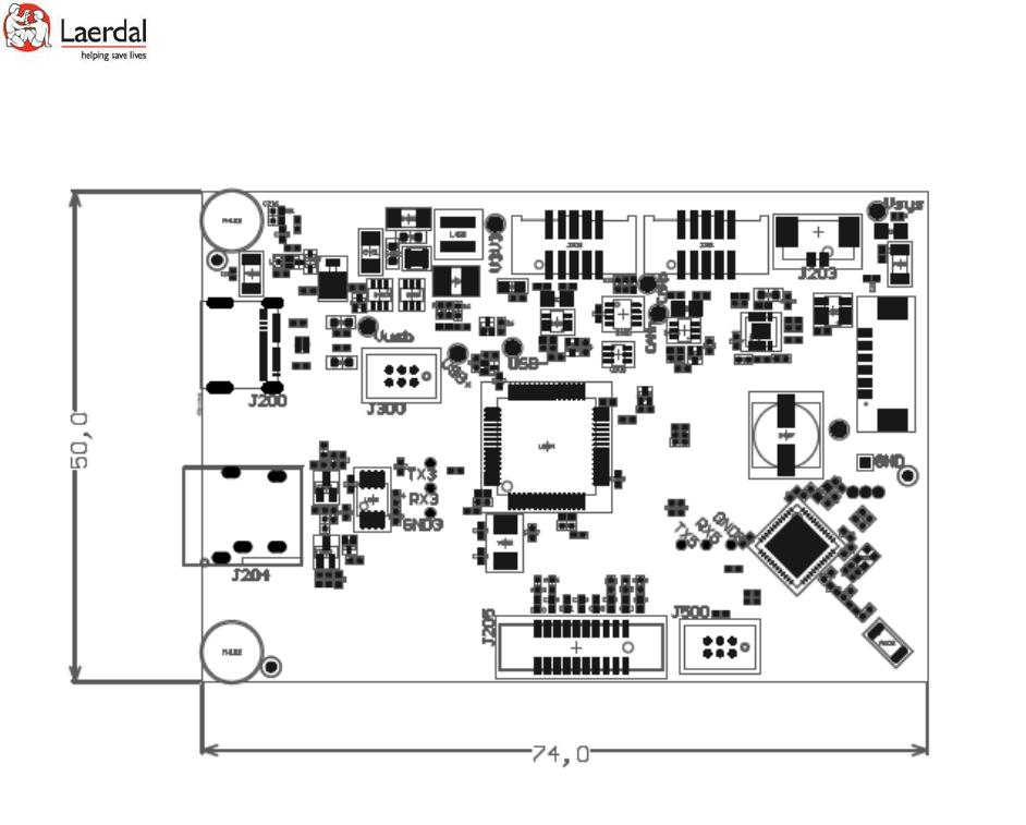
5. Dimensions ............................................................................................................................... 4
6. Power ....................................................................................................................................... 4
6.1. Sources .............................................................................................................................. 4
6.2. Power source switching .................................................................................................... 4
6.3. Board current consumption ............................................................................................. 5
7. Radio ........................................................................................................................................ 5
7.1. Antenna ............................................................................................................................ 5
7.2. Integration radio module into Laerdal CPR manikins ....................................................... 5
8. Module label ............................................................................................................................ 6
9. Regulatory Statements ............................................................................................................ 7
9.1. FCC Statement: ................................................................................................................. 7
9.2. FCC Important Notes: ....................................................................................................... 7
9.3. IC Statement: .................................................................................................................... 8
Table of Figures
Figure 1. Resusci Main Board. Radio part within red line ............................................................................. 1
Figure 2. Dimension in mm ........................................................................................................................... 4

Att 1 to 00054577 rev.B
Resusci Main Board Electronic Design Description Page: 3 of 9
1. Scope
This document describes instructions of how to integrate PCA Resusci Main board radio module in a host
device. The document covers the radio part of the module only. Internal Laerdal Medical documents
covers the application related part of module.
2. Application
Resusci Main board is designed for integration in Laerdal Medical CPR manikins. It is not intended for
integration by others than Laerdal Medical
3. Features
- Power management
- CAN interface
- Bluetooth Low Energy radio (BLE)
- USB interface
- Skillguide interface
- Sound output
- Control panel interface
4. Abbreviations
BLE Bluetooth Low Energy
SoC System on Chip
CPR Cardiopulmonary resuscitation
MCU Micro Controller Unit
Att 1 to 00054577 rev.B
Resusci Main Board Electronic Design Description Page: 4 of 9
5. Dimensions
Figure 2. Dimension in mm
6. Power
6.1. Sources
Battery:
Minimum battery voltage: 3,6V. Board is designed to use minimum 4 alkaline cells connected in series
with a battery cutout voltage of 0,9V per cell
Maximum battery voltage is 14V
USB power:
Input voltage 5V±5%
6.2. Power source switching
Circuit is designed to use USB power when this is present. Main MCU and BLE SoC will always be
powered but will be in a low current mode (stop mode) when system is off.
Logic:
USB voltage > ca.2,9V → USB is source
USB voltage < ca.2,9V → Battery is source
Att 1 to 00054577 rev.B
Resusci Main Board Electronic Design Description Page: 5 of 9
6.3. Board current consumption
OFF mode: 65±10uA@Vin=6V
ON mode (without CAN modules/control panel):28±3mA@Vin=6V
7. Radio
Based on Nordic Semiconductor nRF52832
Bluetooth v4.2
Integrated Antenna only
Integrated DC-DC converter
Radio is controlled by Nordic Semiconductor Softdevice version S132
Operating Frequency Range 1: 2402 MHz to 2480 MHz
Modulation: GFSK
Antenna Gain: -0,5dBi
Overall highest e.i.r.p. : 0dBm
Occupied bandwidth: 1,1 MHz
Radio type: Adaptive equipment without possibility to change to non-adaptive
7.1. Antenna
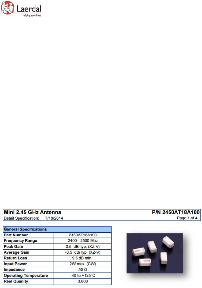
Johanson Technology chip antenna 2450AT18A100
7.2. Integration radio module into Laerdal CPR manikins
• For best range, place module so that metal parts are kept away from radio parts. Especially large
grounded metal should be avoided. Small ungrounded parts as screws are not critical, but RF
performance should be evaluated if placed closer than 5mm to antenna or antenna track from
nRF52832.
• Metal enclosure covering antenna should not be used
• If module is to be co-located with other radio transmitters, regulatory approvals have to be re-
evaluated
Att 1 to 00054577 rev.B
Resusci Main Board Electronic Design Description Page: 6 of 9
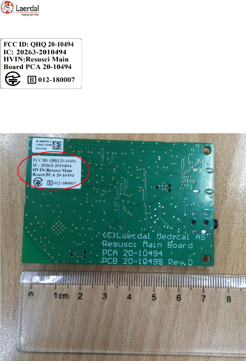
8. Module label
The label is located on the PCA. It is approximately 1 cm high and 2 cm wide – see picture below for label
placement and size.
The HVIN (Resusci Main Board PCA 20-10494) is labeled on the board (see information encircled
in picture below).

Att 1 to 00054577 rev.B
Resusci Main Board Electronic Design Description Page: 7 of 9
9. Regulatory Statements
Note: Regulatory Statements are for reference only pending the completion of testing and approvals.
For this module, Laerdal Medical will be both the manufacturer and OEM integrator.
9.1. FCC Statement:
This device has been tested and found to comply with part 15 of the FCC rules. These limits are designed
to provide reasonable protection against harmful interference in a residential installation. This
equipment generates, uses and can radiate radio frequency energy and, if not installed and used in
accordance with the instructions, may cause harmful interference to radio communications. However,
there is no guarantee that interference will not occur in a particular installation. If this equipment does
cause harmful interference to radio or television reception, which can be determined by turning the
equipment off and on, the user is encouraged to try to correct the interference by one or more of the
following measures:
• Reorient or relocate the receiving antenna.
• Increase the separation between the equipment and the receiver
• Connect the equipment into an outlet on a circuit different from that to which the receiver is
connected.
• Consult the dealer or an experienced radio/TV technician for help.
Operation is subjected to the following two conditions: (1) This device may no cause harmful
interference, and (2) this device must accept any interference received, including interference that may
cause undesired operation. Note: Modification to this product will void the user’s authority to operate
this equipment.
Note: Modification to this product will void the users’ authority to operate this equipment.
9.2. FCC Important Notes:
(1) FCC Radiation Exposure Statement
This equipment complies with FCC RF radiation exposure limits set forth for an uncontrolled
environment. This transmitter must not be co-located or operating in conjunction with any other
antenna or transmitter.
This equipment complies with Part 15 of the FCC Rules. Operation is subject the following two
conditions:
(1) This device may not cause harmful interference, and
(2) This device must accept any interference received, including interference that may cause undesired
operation.
The devices must be installed and used in strict accordance with the manufacturer’s instructions as
described in this document.
Caution!
The manufacturer is not responsible for any radio or TV interference caused by unauthorized
modifications to this equipment. Such modification could void the user authority to operate the
equipment.
(2) Co-location Warning:

Att 1 to 00054577 rev.B
Resusci Main Board Electronic Design Description Page: 8 of 9
This device and its antenna(s) must not be co-located or operating in conjunction with any other
transmitter antenna.
(3) OEM integration instructions:
This device is intended only for OEM integrators under the following conditions:
The antenna and transmitter must not be co-located with any other transmitter or antenna. The module
shall be only used with the integral antenna(s) that has been originally tested and certified with this
module.
As long as the two (2) conditions above are met, further transmitter testing will not be required.
However, the OEM integrator is still responsible for testing their end-product for any additional
compliance requirements with this module installed (for example, digital device emission, PC peripheral
requirements, etc.)
In the event that these conditions cannot be met (for example certain laptop configuration or co-location
with another transmitter), then the FCC authorization for this module in combination with the host
equipment is no longer considered valid and the FCC ID of the module cannot be used on the final
product. In these and circumstance, the OEM integrator will be responsible for re-evaluating. The end
product (including the transmitter) and obtaining a separate FCC authorization.
Caution!
The OEM is still responsible for verifying compliance with FCC Part 15, subpart B limits for unintentional
radiators through an accredited test facility.
(4) End product labeling:
The final end product must be labeled in a visible area with the following:
• “Contains FCC ID: QHQ 20-10494”
Any similar wording that expresses the same meaning may be used.
The FCC Statement below should also be included on the label. When not possible, the FCC Statement
should be included in the User Manual of the host device.
“This device complies with part 15 of the FCC rules.
Operation is subject to the following two conditions. (1) This device may not cause harmful interference.
(2) This device must accept any interference received, including interference that may cause undesired
operation.”
(5) Information regarding the end user manual:
The OEM integrator has to be aware not to provide information to the end user regarding how to install
or remove this RF module in the user’s manual of the end product which integrates this module. The end
user manual shall include all required regulatory information/warning as show in this manual (Section
15.2(4)).
9.3. IC Statement:
This device complies with Industry Canada license-exempt RSS standard(s). Operation is subject to the
following two conditions: (1) this device may not cause interference, and (2) this device must accept any
interference, including interference that may cause undesired operation of the device.

Att 1 to 00054577 rev.B
Resusci Main Board Electronic Design Description Page: 9 of 9
Le présent appareil est conforme aux CNR d'Industrie Canada applicables aux appareils radio exempts de
licence. L'exploitation est autorisée aux deux conditions suivantes : (1) l'appareil ne doit pas produire de
brouillage, et (2) l'utilisateur de l'appareil doit accepter tout brouillage radioélectrique subi, même si le
brouillage est susceptible d'en compromettre le fonctionnement.
RF exposure warning: The equipment complies with RF exposure limits set forth for an uncontrolled
environment. The antenna(s) used for this transmitter must not be co-located or operating in
conjunction with any other antenna or transmitter.
Avertissement d'exposition RF: L'équipement est conforme aux limites d'exposition aux RF établies pour
un incontrôlés environnement. L'antenne (s) utilisée pour ce transmetteur ne doit pas être co-localisés
ou onctionner en conjonction avec toute autre antenne ou transmetteur .
15.4 IC Important Notes:
1. The OEM integrator has to be aware not to provide information to the end user regarding how to
install or remove this RF module in the user manual of the end product.
The user manual which is provided by OEM integrators for end users must include the following
information in a prominent location.
2. To comply with IC RF exposure compliance requirements, the antenna used for this transmitter must
not be co‐located or operating in conjunction with any other antenna or transmitter, except in
accordance with IC multi‐transmitter product procedures.
3. The final system integrator must ensure there is no instruction provided in the user manual or
customer documentation indicating how to install or remove the transmitter module except such device
has implemented two‐ways authentication between module and the host system.
4. The host device shall be properly labelled to identify the module within the host device. The final end
product must be labeled in a visible area with the following:
• “Contains IC: 20263-2010494 “
Any similar wording that expresses the same meaning may be used.
The IC Statement below should also be included on the label. When not possible, the IC Statement
should be included in the User Manual of the host device.
“This device complies with Industry Canada license-exempt RSS standard(s). Operation is subject to the
following two conditions: (1) this device may not cause interference, and (2) this device must accept any
interference, including interference that may cause undesired operation of the device.
Le présent appareil est conforme aux CNR d'Industrie Canada applicables aux appareils radio exempts de
licence. L'exploitation est autorisée aux deux conditions suivantes : (1) l'appareil ne doit pas produire de
brouillage, et (2) l'utilisateur de l'appareil doit accepter tout brouillage radioélectrique subi, même si le
brouillage est susceptible d'en compromettre le onctionnement.”