Laird Connectivity 1001 TiWi-C-W Module User Manual
LS Research, LLC TiWi-C-W Module Users Manual
Contents
- 1. Users Manual
- 2. Users Manual V2
Users Manual
TiWi-C-W Module
APPLICATION GUIDE
The information in this document is subject to change without notice.
TiWi-C-W User Manual.docx Copyright © 2015 LSR Page 1 of 33
TIWI-C-W MODULE
APPLICATION GUIDE
Last updated
February 23, 2015

TiWi-C-W Module
APPLICATION GUIDE
The information in this document is subject to change without notice.
TiWi-C-W User Manual.docx Copyright © 2015 LSR Page 2 of 33
Table of Contents
1 Introduction ................................................................................................................... 3
1.1 Purpose & Scope ....................................................................................................................... 3
1.2 Applicable Documents ............................................................................................................... 3
2 TiWi-C-W Module and Accessories .............................................................................. 4
3 TiWi-C-W Approved Antenna Specifications ............................................................... 5
3.1 Chip Antenna Specifications...................................................................................................... 5
3.2 LSR FlexPIFA Antenna Specifications ...................................................................................... 7
3.3 Dipole Antenna Specifications ................................................................................................. 11
4 PCB Layout Requirements ......................................................................................... 14
4.1 4-Layer Trace Antenna Design................................................................................................ 15
4.2 2-Layer Trace Antenna Design................................................................................................ 21
5 EMC Compliance ......................................................................................................... 26
5.1 Summary ................................................................................................................................. 26
5.2 Module Integration Considerations - Antenna Systems .......................................................... 26
5.3 Module Integration Considerations - Substitute Antenna Systems ......................................... 26
5.4 Module Integration Considerations - Circuit Implementation .................................................. 27
5.5 Module Integration Considerations - Top Assembly................................................................ 27
5.6 Testing Requirements for End-Product ................................................................................... 27
5.7 Design and Production Validation ........................................................................................... 27
5.8 Agency Certifications ............................................................................................................... 28
5.9 Agency Statements ................................................................................................................. 28
5.10 OEM Responsibilities To Comply With FCC and Industry Canada Regulations .................... 30
5.11 OEM Labeling Requirements For End-Product ....................................................................... 31
5.12 OEM End-Product User Manual Statements ........................................................................... 32
6 Contacting LSR ........................................................................................................... 33

TiWi-C-W Module
APPLICATION GUIDE
The information in this document is subject to change without notice.
TiWi-C-W User Manual.docx Copyright © 2015 LSR Page 3 of 33
1 Introduction
1.1 Purpose & Scope
The purpose of this document is to provide details regarding the design and integration
of certified antennas to the TiWi-C-W module. It covers all three certified antenna
options, which consist of a ceramic chip, dipole, and LSR FlexPIFA antenna. It will
inform the designer as to the required PCB details required to retain the LSR modular
certification for the TiWi-C-W module.
1.2 Applicable Documents
LSR 2.4 GHz FlexPIFA Antenna Datasheet (330-0149)
LSR 2.4 GHz Dipole Antenna Datasheet (330-0016)
LSR U.FL to RPSMA Cable Datasheet (330-0018)
TiWi-C-W Module
APPLICATION GUIDE
The information in this document is subject to change without notice.
TiWi-C-W User Manual.docx Copyright © 2015 LSR Page 4 of 33
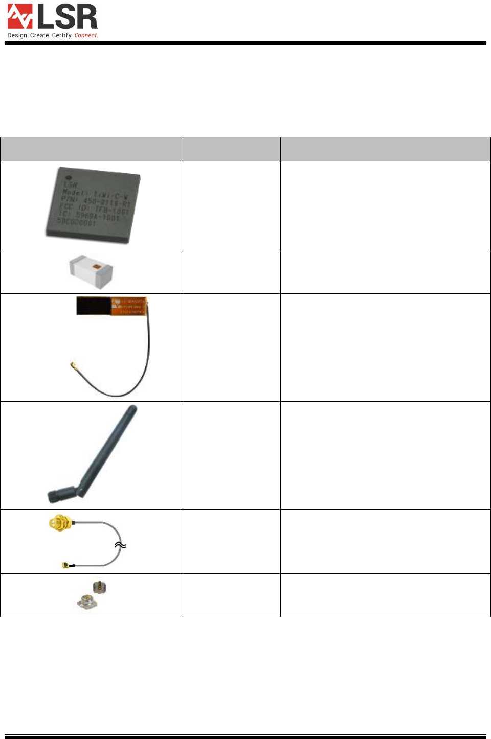
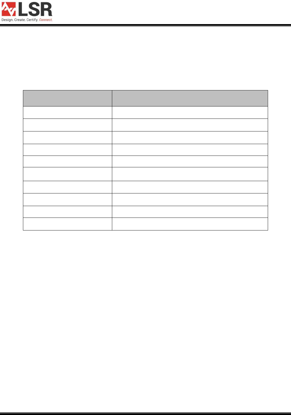
2 TiWi-C-W Module and Accessories
The TiWi-C-W Module is a System in Package (SIP) module. The TiWi-C-W module is
certified with three antennas.
Part Number
Description
LSR 450-0118R
LSR 450-0118C
TiWi-C-W Module, Tape & Reel
TiWi-C-W Module, Cut Tape
Johanson
2450AT18A100
2.4 GHz Ceramic Chip Antenna
LSR
001-0014
2.4 GHz FlexPIFA Antenna with U.FL
Cable
LSR
001-0001
2.4 GHz Dipole Antenna with Reverse
Polarity SMA Connector
LSR
080-0001
U.FL to Reverse Polarity SMA
Bulkhead Cable 105 mm
Hirose
U.FL-R-SMT(10)
PCB Mounted U.FL Connector
Table 1 TiWi-C-W Module and Accessories
TiWi-C-W Module
APPLICATION GUIDE
The information in this document is subject to change without notice.
TiWi-C-W User Manual.docx Copyright © 2015 LSR Page 5 of 33
3 TiWi-C-W Approved Antenna Specifications
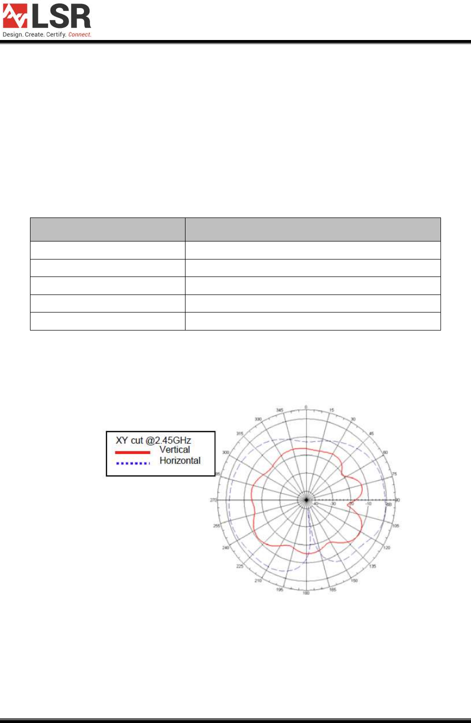
3.1 Chip Antenna Specifications
The Johanson 2450AT18A100 Ceramic Chip Antenna is one option for a trace antenna
design for use with the TiWi-C-W module.
Specification
Value
Manufacturer and Part Number
Johanson 2450AT18A100
Peak Gain
.5 dBi
Type
Ceramic Chip
Polarization
Linear
Frequency
2400-2500MHz
Table 2 Chip Antenna Specifications
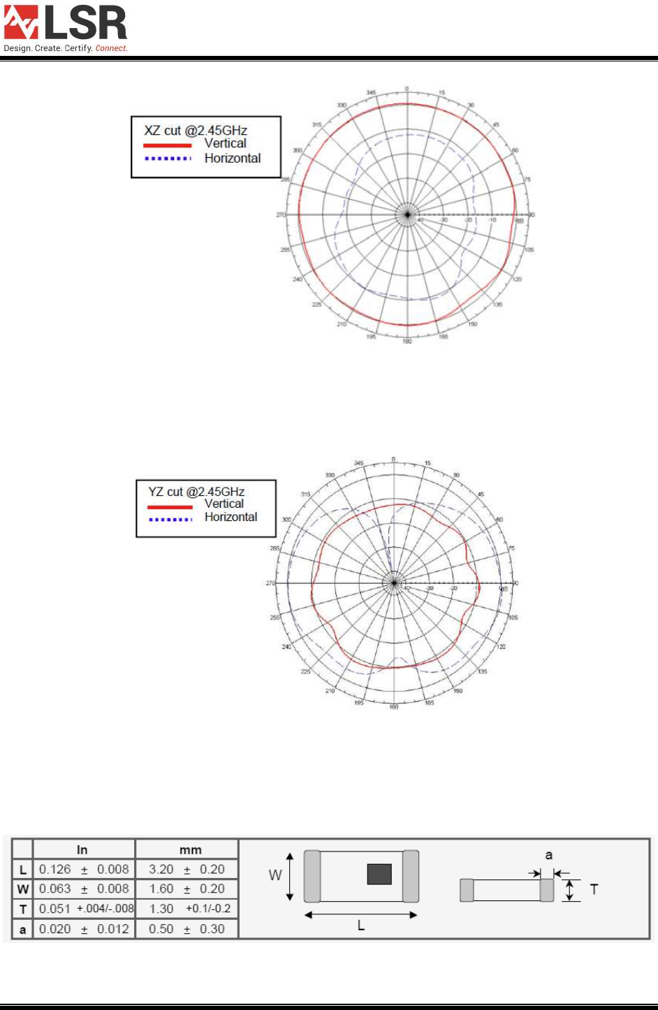
3.1.1 Chip Antenna Typical Radiation Patterns
Figure 1 Chip Antenna XY Cut Radiation Pattern
TiWi-C-W Module
APPLICATION GUIDE
The information in this document is subject to change without notice.
TiWi-C-W User Manual.docx Copyright © 2015 LSR Page 6 of 33
Figure 2 Chip Antenna XZ Cut Radiation Pattern
Figure 3 Chip Antenna YZ Cut Radiation Pattern
3.1.2 Mechanical Dimensions
Figure 4 Chip Antenna Dimensions
TiWi-C-W Module
APPLICATION GUIDE
The information in this document is subject to change without notice.
TiWi-C-W User Manual.docx Copyright © 2015 LSR Page 7 of 33
3.2 LSR FlexPIFA Antenna Specifications
The LSR 001-0014 FlexPIFA Antenna w/U.FL cable is used in conjunction with the
Hirose PCB mounted U.FL connector, to provide an externally mounted antenna solution
for the TiWi-C-W module.
Specification
Value
Manufacturer and Part Number
LSR 001-0014
Peak Gain
2.0 dBi
Type
Flexible Planar Inverted F Antenna (FlexPIFA)
Polarization
Linear
Frequency
2400-2480 MHz
Table 3 LSR FlexPIFA Antenna Specifications
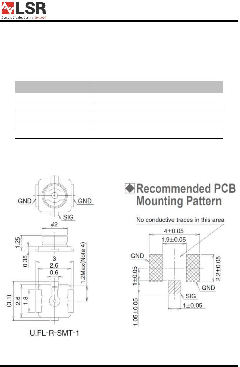
3.2.1 U.FL Connector Drawing
Figure 5 – U.FL Connector Drawing
TiWi-C-W Module
APPLICATION GUIDE
The information in this document is subject to change without notice.
TiWi-C-W User Manual.docx Copyright © 2015 LSR Page 8 of 33
3.2.2 Mechanical Dimensions
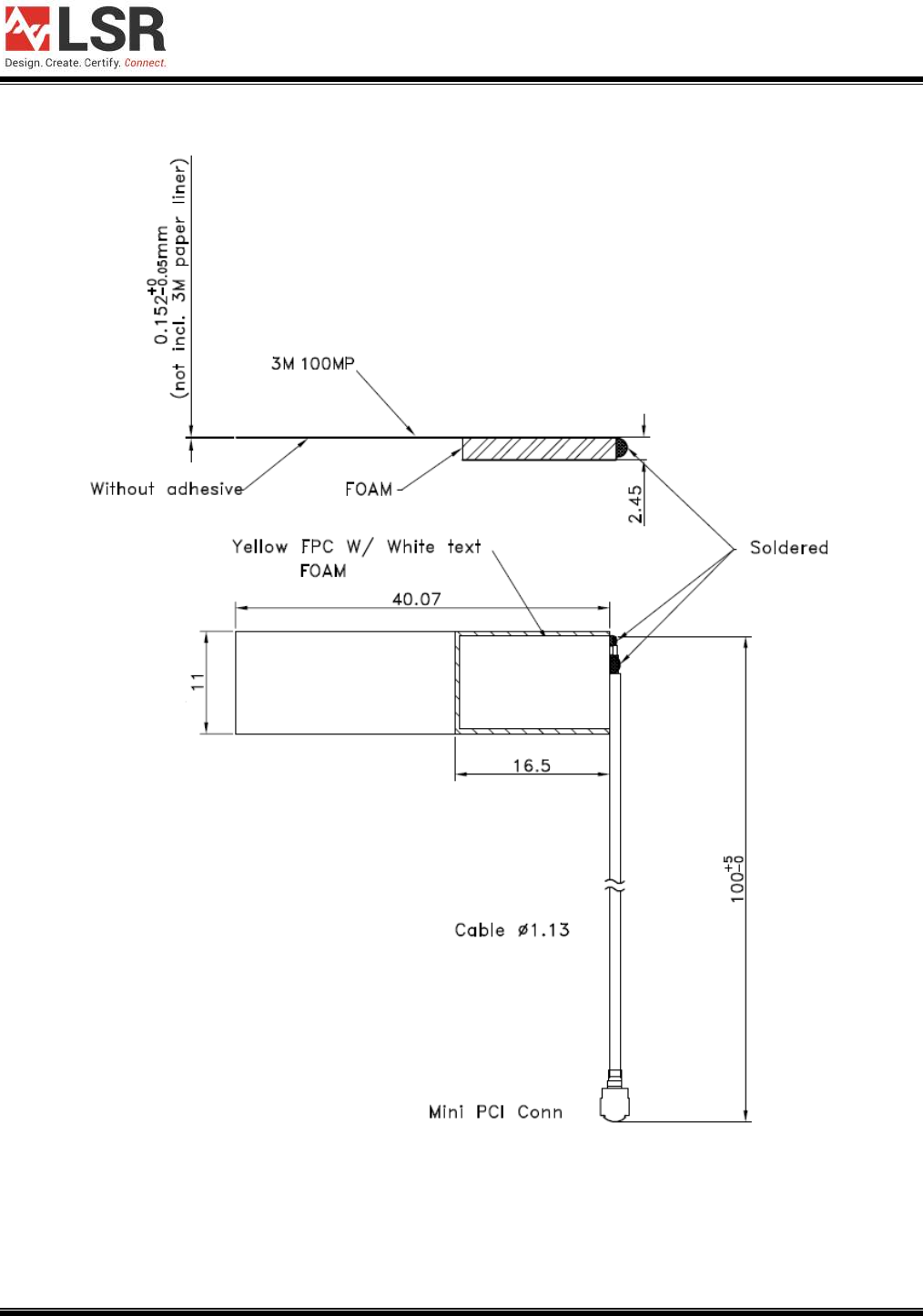
Figure 6 LSR FlexPIFA Antenna Dimensions
TiWi-C-W Module
APPLICATION GUIDE
The information in this document is subject to change without notice.
TiWi-C-W User Manual.docx Copyright © 2015 LSR Page 9 of 33
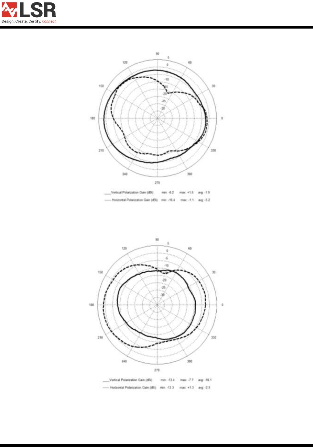
3.2.1 FlexPIFA Antenna Typical Radiation Patterns
Figure 7 FlexPIFA Antenna Azimuth Plane Radiation Pattern
Figure 8 FlexPIFA Antenna Primary Elevation Radiation Pattern
TiWi-C-W Module
APPLICATION GUIDE
The information in this document is subject to change without notice.
TiWi-C-W User Manual.docx Copyright © 2015 LSR Page 10 of 33
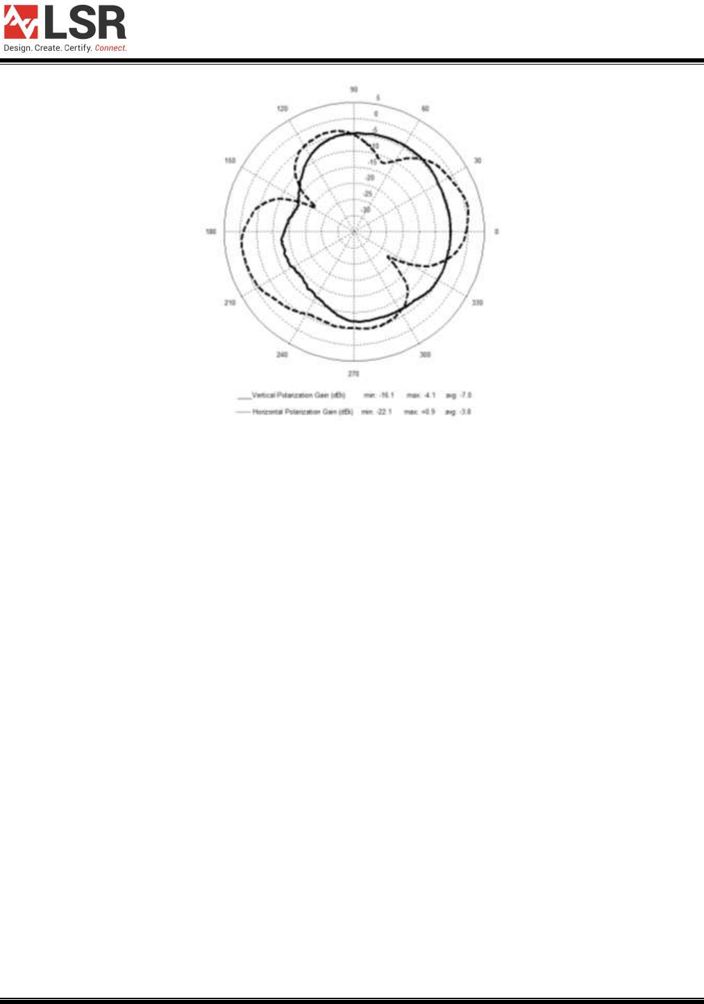
Figure 9 FlexPIFA Antenna Secondary Elevation Radiation Pattern
TiWi-C-W Module
APPLICATION GUIDE
The information in this document is subject to change without notice.
TiWi-C-W User Manual.docx Copyright © 2015 LSR Page 11 of 33
3.3 Dipole Antenna Specifications
The LSR 001-0001 Dipole Antenna is used in conjunction with the LSR 080-0001 U.FL to
Reverse Polarity SMA Cable, and the Hirose PCB mounted U.FL connector Figure 5, to provide
an externally mounted antenna solution for the TiWi-C-W module.
Specification
Value
Manufacturer and Part Number
LSR 001-0001
Gain
+2 dBi
Impedance
50 ohms, Nominal
Type
Dipole
Polarization
Linear Vertical
VSWR
≤2.5:1, Maximum
Frequency
2400-2500MHz
Weight
13g
Size
105 mm x 10 mm
Antenna Color
Black
Table 4 Dipole Antenna Specifications
TiWi-C-W Module
APPLICATION GUIDE
The information in this document is subject to change without notice.
TiWi-C-W User Manual.docx Copyright © 2015 LSR Page 12 of 33
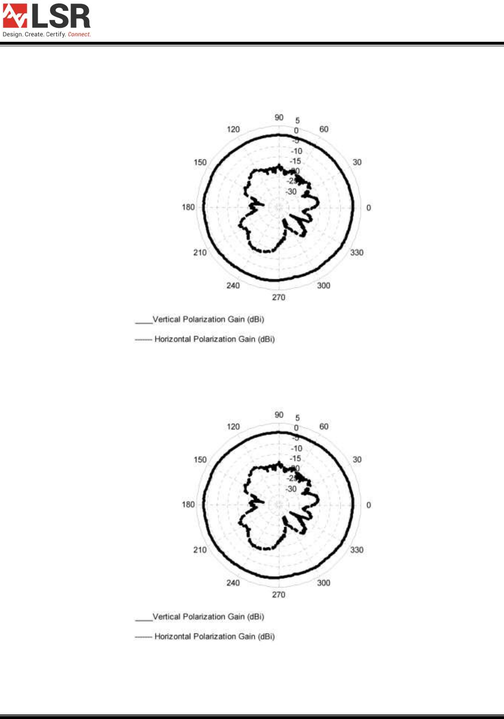
3.3.1 Dipole Antenna Typical Radiation Patterns
Figure 10 Dipole Antenna Radiation Pattern (LSR Antenna Straight @ 2405 MHz)
Figure 11 Dipole Antenna Radiation Pattern (LSR Antenna Folded 90o @ 2405 MHz)
TiWi-C-W Module
APPLICATION GUIDE
The information in this document is subject to change without notice.
TiWi-C-W User Manual.docx Copyright © 2015 LSR Page 13 of 33
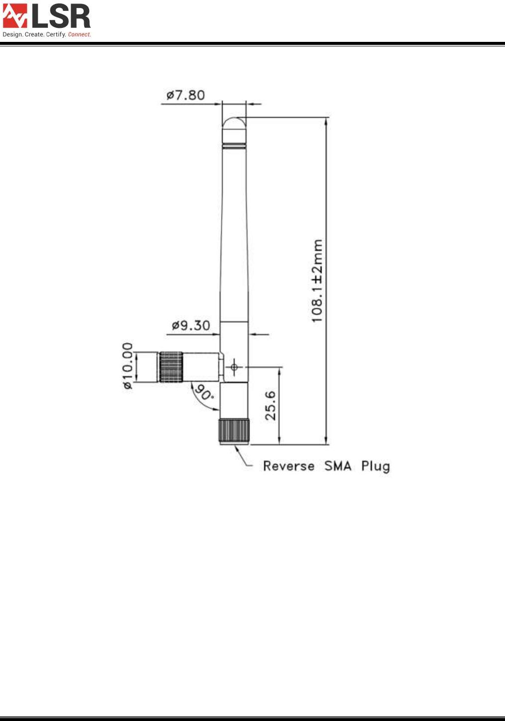
3.3.2 Mechanical Dimensions
Figure 12 LSR Dipole Antenna Dimensions
TiWi-C-W Module
APPLICATION GUIDE
The information in this document is subject to change without notice.
TiWi-C-W User Manual.docx Copyright © 2015 LSR Page 14 of 33
4 PCB Layout Requirements
Since this module and its associated set of approved antennas has been certified by the FCC
and Industry Canada (IC) as a Modular Radio, the end user is authorized to integrate this
module into an end-product, and is solely responsible for the Unintentional Emissions levels
produced by the end-product.
In order to preserve the Modular Radio certifications, the integrator of the module must abide by
the PCB layout recommendations outlined in the following paragraphs. Any divergence from
these recommendations will invalidate the modular radio certifications and require the integrator
to re-certify the module and/or end-product.
The module must be used with one of the approved antennas:
1. Johanson Technology 2450AT18A100 Ceramic Chip Antenna.
2. LSR 001-0001 center-fed 2.4 GHz dipole antenna and 080-0001 U.FL to Reverse Polarity
SMA connector cable.
3. LSR 001-0014 2.4 GHz FlexPIFA Antenna w/U.FL cable.
The module must be follow one of two trace antenna designs. The primary trace antenna
design is based on a 4-Layer PCB, and the secondary trace antenna design is based on a 2-
Layer PCB. Both trace antenna design CAD packages, which consist of the schematics, Bill of
Materials (BOM), and PCB Layout are available from LSR.
Visit the LSR web site (http://www.lsr.com/) for current PCB and Schematic CAD files.
Please use the latest CAD files from the LSR web site when incorporating the TiWi-C-W module
into a new design. CAD files are provided in native Mentor Grahics PADS PCB and PADS
Logic formats, as well as ASCII, Gerber, and PDF formats. CAD files can also be translated to
most popular CAD package. Contact LSR Tech support for CAD translation.
TiWi-C-W Module
APPLICATION GUIDE
The information in this document is subject to change without notice.
TiWi-C-W User Manual.docx Copyright © 2015 LSR Page 15 of 33
4.1 4-Layer Trace Antenna Design
2.4 GHz Chip Antenna Implementation
When using the certified Chip Antenna (Johanson Part Number 2450AT18A100), the PCB
layout shown in Figure 13 should be followed. It is acceptable to keep the U.FL circuitry J7 and
J8, and the U.FL connectors can either be populated or not.
2.4 GHz Dipole Antenna Implementation
When using the certified 2.4 GHz Dipole Antenna and U.FL to RPSMA Cable, the PCB layout
shown in Figure 14 should be followed. Components J7 and J8 should be populated as shown
in the schematic.
2.4 GHz FlexPIFA Antenna
When using the certified 2.4 GHz FlexPIFA Antenna w/U.FL cable, the PCB layout shown in
Figure 14 should be followed. Components J7 and J8 should be populated as shown in the
schematic.
TiWi-C-W Module
APPLICATION GUIDE
The information in this document is subject to change without notice.
TiWi-C-W User Manual.docx Copyright © 2015 LSR Page 16 of 33
Figure 13 4-Layer Chip Antenna Trace Design PCB Layout
TiWi-C-W Module
APPLICATION GUIDE
The information in this document is subject to change without notice.
TiWi-C-W User Manual.docx Copyright © 2015 LSR Page 17 of 33
Figure 14 4-Layer Dipole and FlexPIFA Trace Antenna PCB Layout
TiWi-C-W Module
APPLICATION GUIDE
The information in this document is subject to change without notice.
TiWi-C-W User Manual.docx Copyright © 2015 LSR Page 18 of 33
Figure 15 4-Layer Trace Antenna Design Schematic
TiWi-C-W Module
USER GUIDE
The information in this document is subject to change without notice.
TiWi-C-W User Manual.docx Copyright © 2015 LSR Page 19 of 33
Qty
PCB Ref
Pop
Option
Value
Tolerance
Manufacturer
Mfg Part Number
2
ANT1 ANT2
Johanson
Technology
2450AT18A100
3
C1 C2 C6
10uF
+/- 10%
Murata
GRM21BR61A106KE19
7
C3 C5 C8 C9 C10 C11 C12
100nF
+/- 10%
Murata
GRM155R71C104KA88
2
C7 C13
10pF
+/- 5%
Murata
GRM1555C1H100JA01
2
C14 C15
1.0pF
+/-0.25pF
Murata
L-07C2N2SV6T
2
D1 D2
Infineon
1
FB1
Taiyo Yuden
FBMH1608HL601-T
1
J1
Molex
1050170001
1
J2
Sullins
NRPN082PAEN-RC
2
J6 J10
Sullins
NRPN141PARN-RC
2
J7 J8
Hirose
U.FL-R-SMT-1
1
J9
NP
Tag-Connect
TC2050-IDC
1
J12
NP
TE
Connectivity
2-644803-2
1
JMP1
Sullins
SPN02SXCN-RC
4
JMP2 JMP3 JMP4 JMP5
NP
LSR
000-0000
1
JP1
Sullins
NRPN031PARN-RC
2
L1 L2
2.7nH
+/- 0.3nH
Johanson
Technology
L-07C2N7SV6T
1
L5
2.2uH
+/- 20%
Coilcraft
LPS3015-222ML
1
LED1
Kingbright
WP7113SRC/DU
1
LED2
Kingbright
WP7113CGCK
1
LED3
Super Bright
LEDs
RL5-RGB-DCC
1
MOD1
LSR
450-0118
2
PB_CAP1 PB_CAP2
NP
E-Switch
4JWHT
1
PCB1
LSR
750-00570
6
Q1 Q2 Q3 Q4 Q5 Q6
Fairchild
FDN340P
2
R3 R4
0
50m Ohm
Max
KOA
RK73Z1ET
3
R1 R7 R8
NP
0
50m Ohm
Max
KOA
RK73Z1ET
1
R2
130
5%
KOA
RK73B1ET131J
1
R6
24
5%
KOA
RK73B1ET240J
1
R5
56
5%
KOA
RK73B1ET560J
1
R9
100
5%
KOA
RK73B1ET101J
1
R10
270
5%
KOA
RK73B1ET270J
11
R11 12 R13 R14 R15 R16
R17 R18 R19 R20 R21
10K
5%
KOA
RK73B1ET103J
3
S1 S2 S6
E-Switch
TL3301PF160QG
2
S3S4
NP
E-Switch
TL1100FF160Q
1
S5
C&K
KMS221GPLFS
1
S7
E-Switch
EG2207
1
U1
Texas
Instruments
TMP006AIYZF
1
U2
Texas
Instruments
TPS63001DRC
1
U4
Maxim
Integrated
MAX44009EDT+
1
Z1
Epcos
B72590D0050H160

TiWi-C-W Module
USER GUIDE
The information in this document is subject to change without notice.
TiWi-C-W User Manual.docx Copyright © 2015 LSR Page 20 of 33
Notes:
# designates mfg material package option.
NP designates a component that is not populated.
Table 5 – 4-Layer Trace Antenna Design Bill of Materials (BOM)
TiWi-C-W Module
USER GUIDE
The information in this document is subject to change without notice.
TiWi-C-W User Manual.docx Copyright © 2015 LSR Page 21 of 33
4.2 2-Layer Trace Antenna Design
2.4 GHz Chip Antenna Implementation
When using the certified Chip Antenna (Johanson Part Number 2450AT18A100), the PCB
layout shown in Figure 16 should be followed. It is acceptable to keep the U.FL circuitry J7 and
J8, and the U.FL connectors can either be populated or not.
2.4 GHz Dipole Antenna Implementation
When using the certified 2.4 GHz Dipole Antenna and U.FL to RPSMA Cable, the PCB layout
shown in Figure 17 should be followed. Components J7 and J8 should be populated as shown
in the schematic.
2.4 GHz FlexPIFA Antenna
When using the certified 2.4 GHz FlexPIFA Antenna w/U.FL cable, the PCB layout shown in
Figure 17 should be followed. Components J7 and J8 should be populated as shown in the
schematic.
Figure 16 2-Layer Chip Antenna Trace Design PCB Layout
TiWi-C-W Module
USER GUIDE
The information in this document is subject to change without notice.
TiWi-C-W User Manual.docx Copyright © 2015 LSR Page 22 of 33
Figure 17 2-Layer Dipole and FlexPIFA Trace Antenna PCB Layout
TiWi-C-W Module
USER GUIDE
The information in this document is subject to change without notice.
TiWi-C-W User Manual.docx Copyright © 2015 LSR Page 23 of 33
Figure 18 2-Layer Trace Antenna Design Schematic
TiWi-C-W Module
USER GUIDE
The information in this document is subject to change without notice.
TiWi-C-W User Manual.docx Copyright © 2015 LSR Page 24 of 33
Qty
PCB Ref
Pop
Option
Value
Tolerance
Manufacturer
Mfg Part Number
2
ANT1 ANT2
Johanson
Technology
2450AT18A100
6
C1 C2 C6 C20 C21 C23
10uF
+/- 10%
Murata
GRM21BR61A106KE19#
11
C4 C5 C8 C9 C10 C11
C15 C16 C19 C22 C24
100nF
+/- 10%
Murata
GRM155R71C104KA88#
1
C7
8.2pF
+/- 0.5pF
Murata
GRM1555C1H8R2DZ01#
1
C13
10pF
+/- 5%
Murata
GRM1555C1H100JA01#
2
C17 C18
12pF
+/- 5%
Murata
GRM1555C1H120JA01#
1
C25
1.5pF
+/- 0.25pF
Murata
GRM1555C1H1R5CA01#
2
D1 D2
On Semiconductor
MBR120VLSFT#G
2
D3 D4
Infineon
ESD112B102ELE6327XTMA1
1
FB1
Taiyo Yuden
FBMH1608HL601-#
1
J1
Molex
105017-0001
1
J2
Sullins
NRPN082PAEN-RC
1
J3
NP
Sullins
NRPN081PAEN-RC
1
J4
Sullins
PBC02SAAN
1
J5
AMP
640456-2
2
J6 J10
Sullins
PBC14SAAN
2
J7 J8
Hirose
U.FL-R-SMT-1#
1
J9
NP
Tag-Connect
TC2050-IDC
1
J11
NP
Sullins
PRPC005SAAN-RC
4
JMP2 JMP3 JMP4 JMP5
NP
LSR
000-0000
1
L1
3.9nH
+/- 0.3nH
Johanson
Technology
L-07C3N9SV6#
1
L2
2.7nH
+/- 0.3nH
Johanson
Technology
L-07C2N7SV6#
1
L4
2.2nH
+/- 0.3nH
Johanson
Technology
L-07C2N2SV6#
1
L5
2.2uH
+/- 20%
Coilcraft
LPS3015-222MR#
1
LED3
Kingbright
APTB1612ESGC-F01
1
MOD1
LSR
450-0118
1
PCB1
LSR
750-00571
3
Q1 Q2 Q6
Fairchild
FDN340P
2
R3 R4
0
50mOhm
Max
KOA
RK73Z1ET#
3
R1 R8 R9
NP
0
50mOhm
Max
KOA
RK73Z1ET#
7
R2 R7 R12 R13 R16 R17
R19
10K
5%
KOA
RK73B1ET#103J
2
R5 R6
270
1%
Vishay
CRCW0402270RFK#
2
S1 S6
E-Switch
TL3301PF160QG
2
S2 S7
E-Switch
EG2207
1
S5
C&K
KMS221GPLFS
1
U2
Texas Instruments
TPS63001DRC#
1
U3
Texas Instruments
MSP430G2333IRHB32#
1
U4
Texas Instruments
TPS3803G15DCK#
1
U5
Texas Instruments
TMP006AIYZF#
1
U6
Maxim Integrated
MAX44009EDT+#
1
U8
Texas Instruments
TPS3803-01DCK#
1
Y2
NP
ECS
ECS-.327-12.5-34B
1
Z1
Epcos
B72590D0050H1#

TiWi-C-W Module
USER GUIDE
The information in this document is subject to change without notice.
TiWi-C-W User Manual.docx Copyright © 2015 LSR Page 25 of 33
Notes:
# designates mfg material package option.
NP designates a component that is not populated.
Table 6 2-Layer Trace Antenna Design Bill of Materials (BOM)

TiWi-C-W Module
USER GUIDE
The information in this document is subject to change without notice.
TiWi-C-W User Manual.docx Copyright © 2015 LSR Page 26 of 33
5 EMC Compliance
5.1 Summary
The TiWi-C-W module has been tested and approved as a Modular Radio in accordance with
the appropriate FCC and IC standards. The supporting test data may be found in the modular
test report.
Since this module and its associated set of approved antennas have been certified as a Modular
Radio, this allows the end user to integrate this module into an end-product without the
requirement of re-certifying the radio module. The module-integrator is responsible for the
unintentional conducted and radiated emissions and must verify that the integrated product is
compliant with the rules associated with unintentional radiators. The module integrator is also
required to maintain an engineering record of the verification testing and declare on the product
through proper labeling and marking that the device is compliant with these particular rules.
The installed module’s FCC ID and IC numbers need to be clearly marked on the product with
the following verbiage “Contains FCC ID: TFB-1001” and "Contains IC: 5969A-1001".
5.2 Module Integration Considerations - Antenna Systems
The module must be used with one of the approved antennas:
1) LSR 001-0001 2.4 GHz center-fed dipole antenna and LSR 080-0001 U.FL to Reverse Polarity SMA
connector cable.
2) LSR 001-0014 2.4 GHz FlexPIFA antenna.
3) Johanson 2450AT18A100 chip antenna.
The antenna should be placed such that it is minimally disturbed by the product’s packaging
material. The incorporation of the largest practical free-space clearance around the antenna is
important for maximizing overall performance. Further, the antenna must be placed such that at
least a 20 cm separation distance is maintained from the antenna to all other radio transmitters.
5.3 Module Integration Considerations - Substitute Antenna Systems
The module’s certification is only valid for the list of approved antennas presented in section 4.
However, substitute antennas may be used in place of the approved antenna only if the
antennas are of the same type and the peak gain is less than or equal to the peak gain of the
similar approved antenna. Also the antennas should have similar in-band and out-of-band
characteristics.

TiWi-C-W Module
USER GUIDE
The information in this document is subject to change without notice.
TiWi-C-W User Manual.docx Copyright © 2015 LSR Page 27 of 33
5.4 Module Integration Considerations - Circuit Implementation
It is recommended that all connection PCB (printed circuit board) traces to the power supply and
digital control terminal be as short as possible. Though not necessarily required in all cases, it
is a best practice to provide an optional shunt capacitor placement at the module pin on all
active and routed power supply and digital control lines. Further, a series damping resistor
placement should be incorporated between the module pin/shunt capacitor node and the
source/sink of the digital control signals. This provides for effective bypassing and decoupling
of digital lines from the radio module, in the event that the application circuit has longer power
supply and digital routing.
5.5 Module Integration Considerations - Top Assembly
In addition to the recommendations given for the antenna systems and the module placement
onto a product PCB, it is recommended that all wiring and interconnect systems within the
product be not routed anywhere close the module and its associated circuitry on the PCB, doing
so could change the emission characteristics of the module.
5.6 Testing Requirements for End-Product
Once the module is integrated and the product realized in a mobile or portable configuration, the
product must be tested and follow the verification process for Unintentional Conducted and
Radiated Emissions in accordance to the FCC and IC guidelines. The module needs to be
powered and placed in the receive mode for this test. The receiver must be tuned to its lowest
frequency channel, mid-frequency channel, and highest frequency channel. The supporting test
data does not need to be submitted to the FCC or IC.
5.7 Design and Production Validation
Applications of the WLAN transceiver are supported by a specific set of antenna sub-systems:
chip antennas driven through PCB traces and matching networks, and external cabled antennas
driven through U.FL connectors. The antenna subsystem designs are validated in initial
engineering tests prior to production release. Throughout the production life of the module, both
AQL (Acceptable Quality Level) and sample tests are performed to check process stability of the
modules’ conducted performance. The antenna subsystems are periodically sampled on an
AQL basis and checked for performance stability over the production process. Both the initial
engineering design validation and the production sampling use the same procedure, techniques,
and equipment.
The antenna subsystems are tested at a 50 Ohm test point reference plane for the driving point
reflection parameters (1-port S-parameters) to characterize the return and mismatch losses.
The module is placed in a special engineering/production only CW mode and the output power
is measured at various frequencies of interest (low, middle, high channels) to normalize
consequent antenna Effective Radiated Power (ERP) pattern measurements to obtain antenna
power gain in dBi (decibels above isotropic). The power gain patterns are analyzed for peak
and average gain, and are monitored for statistical stability or stationarity.
This process is again performed for both initial design validation and production sample-basis
test and validation.
TiWi-C-W Module
USER GUIDE
The information in this document is subject to change without notice.
TiWi-C-W User Manual.docx Copyright © 2015 LSR Page 28 of 33
5.8 Agency Certifications
FCC ID: TFB-1001, 15.247
IC ID: 5969A-1001, RSS 210
CE: Compliant to standards EN 60950-1, EN 300 328, and EN 301 489
5.9 Agency Statements
Federal Communication Commission Interference Statement
This equipment has been tested and found to comply with the limits for a Class B digital device,
pursuant to Part 15 of the FCC Rules. These limits are designed to provide reasonable
protection against harmful interference in a residential installation. This equipment generates
uses and can radiate radio frequency energy and, if not installed and used in accordance with
the instructions, may cause harmful interference to radio communications. However, there is no
guarantee that interference will not occur in a particular installation. If this equipment does
cause harmful interference to radio or television reception, which can be determined by turning
the equipment off and on, the user is encouraged to try to correct the interference by one of the
following measures:
Reorient or relocate the receiving antenna.
Increase the separation between the equipment and receiver.
Connect the equipment into an outlet on a circuit different from that to which the receiver is
connected.
Consult the dealer or an experienced radio/TV technician for help.
This device complies with Part 15 of the FCC Rules. Operation is subject to the following two
conditions: (1) This device may not cause harmful interference, and (2) this device must accept
any interference received, including interference that may cause undesired operation.
FCC CAUTION: Any changes or modifications not expressly approved by the party
responsible for compliance could void the user's authority to operate this
equipment.

TiWi-C-W Module
USER GUIDE
The information in this document is subject to change without notice.
TiWi-C-W User Manual.docx Copyright © 2015 LSR Page 29 of 33
Industry Canada Statements
This Device complies with Industry Canada License-exempt RSS standard(s). Operation is
subject to the following two conditions: (1) this device may not cause interference, and (2) this
device must accept any interference, including interference that may cause undesired operation
of the device.
To reduce potential radio interference to other users, the antenna type and its gain should be so
chosen that the equivalent isotropically radiated power (e.i.r.p.) is not more than that permitted
for successful communication.
This device has been designed to operate with the antenna(s) listed below, and having a
maximum gain of 2.0 dBi (LSR Dipole), 2.0 dBi (LSR FlexPIFA), and 0.5dBi (Johanson Chip).
Antennas not included in this list or having a gain greater than 2.0 dBi, 2.0 dBi, and 0.5dBi are
strictly prohibited for use with this device. The required antenna impedance is 50 ohms.
List of all Antennas Acceptable for use with the Transmitter
1) LSR 001-0001 2.4 GHz center-fed dipole antenna and LSR 080-0001 U.FL to Reverse Polarity SMA
connector cable.
2) LSR 001-0014 2.4 GHz FlexPIFA antenna w/U.FL cable.
3) Johanson 2450AT18A100 chip antenna.
Cet appareil est conforme avec Industrie Canada , exempts de licence standard RSS (s).
L'opération est soumise aux deux conditions suivantes: (1) cet appareil ne peut pas provoquer
d'interférences et (2) cet appareil doit accepter toute interférence, y compris les interférences
qui peuvent causer un mauvais fonctionnement de l'appareil.
Pour réduire le risque d'interférence aux autres utilisateurs, le type d'antenne et son gain
doiventêtre choisis de manière que la puissance isotrope rayonnée équivalente (PIRE) ne
dépasse pascelle permise pour une communication réussie.
Cet appareil a été conçu pour fonctionner avec l'antenne (s) ci-dessous, et ayant un gain
maximum de 2,0 dBi (LSR Dipole), 2.0 dBi (LSR FlexPIFA), et 0.5dBi (Johanson Chip).
Antennes pas inclus dans cette liste ou présentant un gain supérieure à 2,0 dBi, 2.0 dBi, et
0.5dBi sont strictement interdits pour une utilisation avec cet appareil. L'impédance d'antenne
requise est de 50 ohms.
Liste de toutes les antennes acceptables pour une utilisation avec l'émetteur
1) Antenne LSR 001-0001 2.4 GHz de centre-dipôle alimenté et LSR 080-0001 U.FL inverser câble
connecteur SMA à polarité.
2) LSR 001-0014 antenne FlexPIFA 2,4 GHz w/U.FL câble.
3) Antenne de puce Johanson 2450AT18A100.
TiWi-C-W Module
USER GUIDE
The information in this document is subject to change without notice.
TiWi-C-W User Manual.docx Copyright © 2015 LSR Page 30 of 33
5.10 OEM Responsibilities To Comply With FCC and Industry Canada
Regulations
The TiWi-C-W Module has been certified for integration into products only by OEM integrators
under the following conditions:
This device is granted for use in Mobile only configurations in which the antennas used for this
transmitter must be installed to provide a separation distance of at least 20cm from all person
and not be co-located with any other transmitters except in accordance with FCC and Industry
Canada multi-transmitter product procedures.
As long as the two conditions above are met, further transmitter testing will not be required.
However, the OEM integrator is still responsible for testing their end-product for any additional
compliance requirements required with this module installed (for example, digital device
emissions, PC peripheral requirements, etc.).
IMPORTANT NOTE: In the event that these conditions cannot be met (for certain
configurations or co-location with another transmitter), then the FCC and Industry
Canada authorizations are no longer considered valid and the FCC ID and IC
Certification Number cannot be used on the final product. In these circumstances,
the OEM integrator will be responsible for re-evaluating the end product (including
the transmitter) and obtaining a separate FCC and Industry Canada authorization.
Le module de TiWi-C-W a été certifié pour l'intégration dans des produits uniquement par des
intégrateurs OEM dans les conditions suivantes:
Ce dispositif est accordé pour une utilisation dans des configurations mobiles seul dans
lequel les antennes utilisées pour cet émetteur doit être installé pour fournir une distance de
séparation d'au moins 20cm de toute personne et ne pas être colocalisés avec les autres
émetteurs, sauf en conformité avec la FCC et de l'Industrie Canada, multi-
émetteur procédures produit.
Tant que les deux conditions précitées sont réunies, les tests de transmetteurs supplémentaires
ne seront pas tenus. Toutefois, l'intégrateur OEM est toujours responsable de tester leur produit
final pour toutes les exigences de conformité supplémentaires requis avec ce module installé
(par exemple, les émissions appareil numérique, les exigences de périphériques PC, etc.)
NOTE IMPORTANTE: Dans le cas où ces conditions ne peuvent être satisfaites
(pour certaines configurations ou de co-implantation avec un autre émetteur),
puis la FCC et Industrie autorisations Canada ne sont plus considérés comme
valides et l'ID de la FCC et IC numéro de certification ne peut pas être utilisé sur la
produit final. Dans ces circonstances, l'intégrateur OEM sera chargé de réévaluer
le produit final (y compris l'émetteur) et l'obtention d'un distincte de la FCC et
Industrie Canada l'autorisation.

TiWi-C-W Module
USER GUIDE
The information in this document is subject to change without notice.
TiWi-C-W User Manual.docx Copyright © 2015 LSR Page 31 of 33
5.11 OEM Labeling Requirements For End-Product
The TiWi-C-W module is labeled with its own FCC ID and IC Certification Number. The FCC ID
and IC certification numbers are not visible when the module is installed inside another device,
as such the end device into which the module is installed must display a label referring to the
enclosed module. The final end product must be labeled in a visible area with the following:
“Contains Transmitter Module FCC ID: TFB-1001”
“Contains Transmitter Module IC: 5969A-1001”
or
“Contains FCC ID: TFB-1001”
“Contains IC: 5969A-1001”
The OEM of the TiWi-C-W Module must only use the approved antenna(s) listed above, which
have been certified with this module.
Le module de TiWi-C-W est étiqueté avec son propre ID de la FCC et IC numéro de
certification. L'ID de la FCC et IC numéros de certification ne sont pas visibles lorsque le
module est installé à l'intérieur d'un autre appareil, comme par exemple le terminal dans
lequel le module est installé doit afficher une etiquette faisant référence au module ci-
joint. Le produit final doit être étiqueté dans un endroit visible par le suivant:
“Contient Module émetteur FCC ID: TFB-1001"
“Contient Module émetteur IC: 5969A-1001"
ou
“Contient FCC ID: TFB-1001"
“Contient IC: 5969A-1001"
Les OEM du module TiWi-C-W ne doit utiliser l'antenne approuvée (s) ci-dessus, qui ont été
certifiés avec ce module.

TiWi-C-W Module
USER GUIDE
The information in this document is subject to change without notice.
TiWi-C-W User Manual.docx Copyright © 2015 LSR Page 32 of 33
5.12 OEM End-Product User Manual Statements
The OEM integrator should not to provide information to the end user regarding how to install or
remove this RF module or change RF related parameters in the user manual of the end product.
The user manual for the end product must include the following information in a
prominent location:
This device is granted for use in Mobile only configurations in which the antennas used for this
transmitter must be installed to provide a separation distance of at least 20cm from all person
and not be co-located with any other transmitters except in accordance with FCC and Industry
Canada multi-transmitter product procedures.
Other user manual statements may apply.
L'intégrateur OEM ne devraient pas fournir des informations à l'utilisateur final sur la façon
d'installer ou de supprimer ce module RF ou modifier les paramètres liés RF dans le manuel
utilisateur du produit final.
Le manuel d'utilisation pour le produit final doit comporter les informations
suivantes dans unendroit bien en vue:
Ce dispositif est accordé pour une utilisation dans des configurations mobiles seule dans
laquelle les antennes utilisées pour cet émetteur doit être installé pour fournir une distance de
séparation d'au moins 20cm de toute personne et ne pas être co-localisés avec les autres
émetteurs, sauf en conformité avec FCC et Industrie Canada, multi-
émetteur procédures produit.
Autres déclarations manuel de l'utilisateur peuvent s'appliquer.
TiWi-C-W Module
USER GUIDE
The information in this document is subject to change without notice.
TiWi-C-W User Manual.docx Copyright © 2015 LSR Page 33 of 33
6 Contacting LSR
Headquarters LS Research, LLC
W66 N220 Commerce Court
Cedarburg, WI 53012-2636
USA
Tel: (262) 375-4400
Fax: (262) 375-4248
Website www.lsr.com
Technical Support forum.lsr.com
Sales Contact sales@lsr.com
The information in this document is provided in connection with LS Research (hereafter referred to as “LSR”)
products. No license, express or implied, by estoppel or otherwise, to any intellectual property right is granted by
this document or in connection with the sale of LSR products. EXCEPT AS SET FORTH IN LSR’S TERMS AND
CONDITIONS OF SALE LOCATED ON LSR’S WEB SITE, LSR ASSUMES NO LIABILITY WHATSOEVER AND
DISCLAIMS ANY EXPRESS, IMPLIED OR STATUTORY WARRANTY RELATING TO ITS PRODUCTS
INCLUDING, BUT NOT LIMITED TO, THE IMPLIED WARRANTY OF MERCHANTABILITY, FITNESS FOR A
PARTICULAR PURPOSE, OR NON-INFRINGEMENT. IN NO EVENT SHALL LSR BE LIABLE FOR ANY
DIRECT, INDIRECT, CONSEQUENTIAL, PUNITIVE, SPECIAL OR INCIDENTAL DAMAGES (INCLUDING,
WITHOUT LIMITATION, DAMAGES FOR LOSS OF PROFITS, BUSINESS INTERRUPTION, OR LOSS OF
INFORMATION) ARISING OUT OF THE USE OR INABILITY TO USE THIS DOCUMENT, EVEN IF LSR HAS
BEEN ADVISED OF THE POSSIBILITY OF SUCH DAMAGES. LSR makes no representations or warranties with
respect to the accuracy or completeness of the contents of this document and reserves the right to make changes
to specifications and product descriptions at any time without notice. LSR does not make any commitment to
update the information contained herein. Unless specifically provided otherwise, LSR products are not suitable
for, and shall not be used in, automotive applications. LSR’s products are not intended, authorized, or warranted
for use as components in applications intended to support or sustain life.