Laird Connectivity 1003 Sterling - LWB User Manual
LS Research, LLC Sterling - LWB
UserManual.wiki
>
Laird Connectivity
>
1003 User Manual
>
User Manual
Contents
1.
User Manual
2.
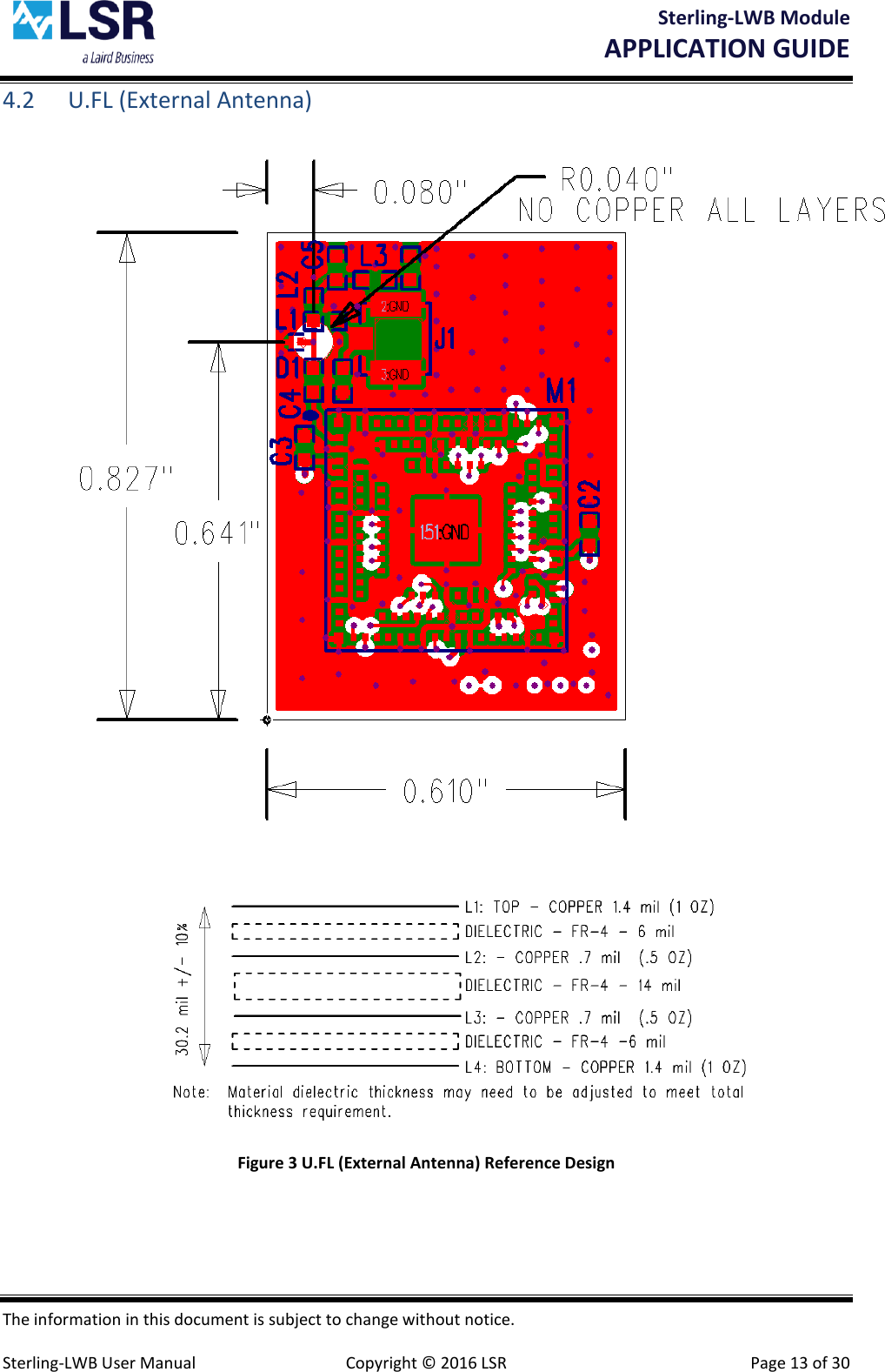
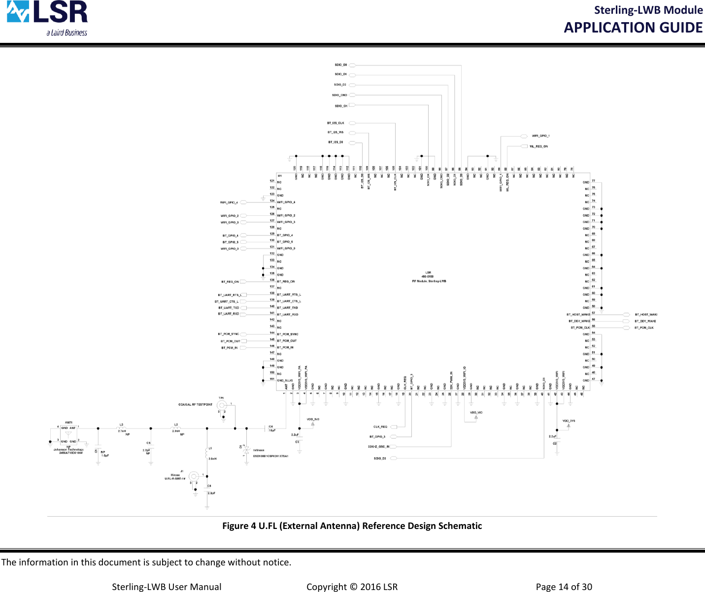
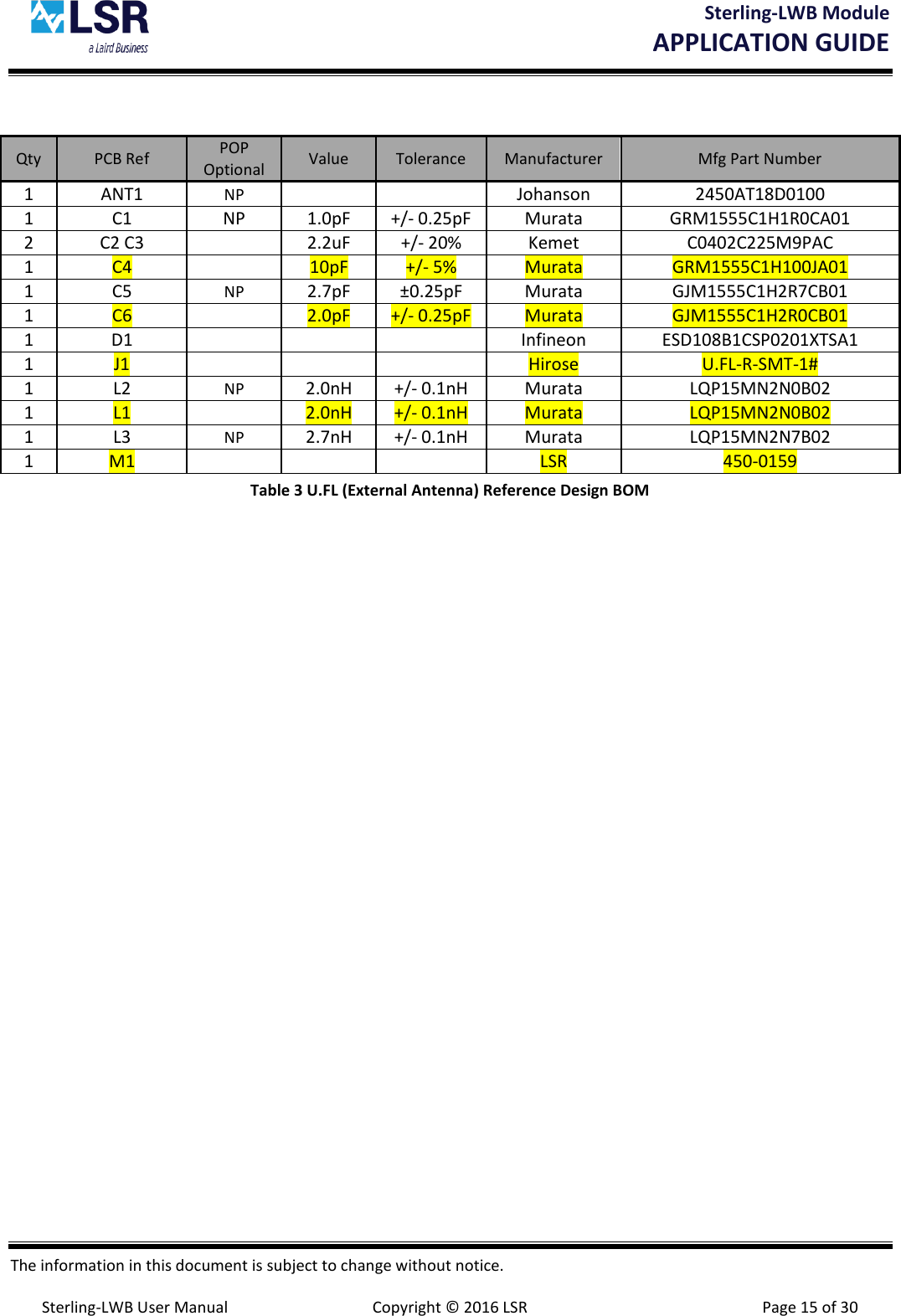
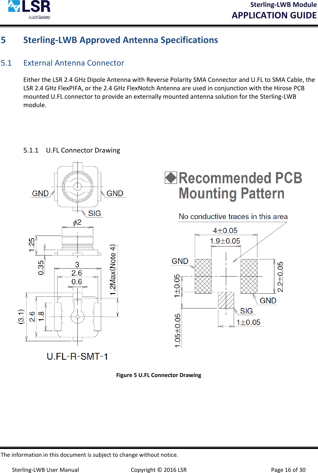
Users Manual 330-0192-R4.2
User Manual
Navigation menu
Upload a User Manual
Namespaces
Wiki Guide
HTML
PDF
Info
Views
User Manual
Discussion / Help
Navigation