Laird Connectivity PH45N 802.11a/b/g/n module User Manual
Laird Technologies 802.11a/b/g/n module Users Manual
UserManual.wiki
>
Laird Connectivity
>
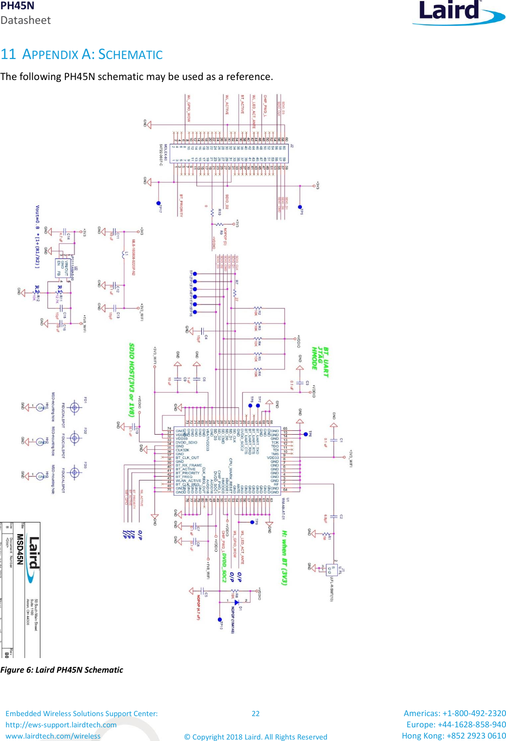
PH45N User Manual
Users Manual
Navigation menu
Upload a User Manual
Namespaces
Wiki Guide
HTML
PDF
Info
Views
User Manual
Discussion / Help
Navigation
![PH45N Datasheet Embedded Wireless Solutions Support Center: http://ews-support.lairdtech.com www.lairdtech.com/wireless 20 © Copyright 2018 Laird. All Rights Reserved Americas: +1-800-492-2320 Europe: +44-1628-858-940 Hong Kong: +852 2923 0610 5150 ~ 5350 MHz is limited to indoor used in the following countries: BE DK IE FR CY LU NL PT SK UK NO BG DE EL HR LV HU AT RO FI LI TR CZ EE ES IT LT MT PL SI SE IS CH Česky [Czech] [Jméno výrobce] tímto prohlašuje, že tento [typ zařízení] je ve shodě se základními požadavky a dalšími příslušnými ustanoveními směrnice 2014/53/EU. Dansk [Danish] Undertegnede [fabrikantens navn] erklærer herved, at følgende udstyr [udstyrets typebetegnelse] overholder de væsentlige krav og øvrige relevante krav i direktiv 2014/53/EU. Deutsch [German] Hiermit erklärt [Name des Herstellers], dass sich das Gerät [Gerätetyp] in Übereinstimmung mit den grundlegenden Anforderungen und den übrigen einschlägigen Bestimmungen der Richtlinie 2014/53/EU befindet. Eesti [Estonian] Käesolevaga kinnitab [tootja nimi = name of manufacturer] seadme [seadme tüüp = type of equipment] vastavust direktiivi 2014/53/EU põhinõuetele ja nimetatud direktiivist tulenevatele teistele asjakohastele sätetele. English Hereby, [name of manufacturer], declares that this [type of equipment] is in compliance with the essential requirements and other relevant provisions of Directive 2014/53/EU. Español [Spanish] Por medio de la presente [nombre del fabricante] declara que el [clase de equipo] cumple con los requisitos esenciales y cualesquiera otras disposiciones aplicables o exigibles de la Directiva 2014/53/EU. Ελληνική [Greek] ΜΕ ΤΗΝ ΠΑΡΟΥΣΑ [name of manufacturer] ΔΗΛΩΝΕΙ ΟΤΙ [type of equipment] ΣΥΜΜΟΡΦΩΝΕΤΑΙ ΠΡΟΣ ΤΙΣ ΟΥΣΙΩΔΕΙΣ ΑΠΑΙΤΗΣΕΙΣ ΚΑΙ ΤΙΣ ΛΟΙΠΕΣ ΣΧΕΤΙΚΕΣ ΔΙΑΤΑΞΕΙΣ ΤΗΣ ΟΔΗΓΙΑΣ 2014/53/EU. Français [French] Par la présente [nom du fabricant] déclare que l'appareil [type d'appareil] est conforme aux exigences essentielles et aux autres dispositions pertinentes de la directive 2014/53/EU. Italiano [Italian] Con la presente [nome del costruttore] dichiara che questo [tipo di apparecchio] è conforme ai requisiti essenziali ed alle altre disposizioni pertinenti stabilite dalla direttiva 2014/53/EU. Latviski [Latvian] Aršo[name of manufacturer /izgatavotājanosaukums] deklarē, ka[type of equipment / iekārtas tips]atbilstDirektīvas 2014/53/EU būtiskajāmprasībām un citiemar to saistītajiemnoteikumiem. Lietuvių [Lithuanian] Šiuo [manufacturer name] deklaruoja, kad šis [equipment type] atitinka esminius reikalavimus ir kitas 2014/53/EU Direktyvos nuostatas. Nederlands [Dutch] Hierbij verklaart [naam van de fabrikant] dat het toestel [type van toestel] in overeenstemming is met de essentiële eisen en de andere relevante bepalingen van richtlijn 2014/53/EU. Malti [Maltese] Hawnhekk, [isem tal-manifattur], jiddikjara li dan [il-mudel tal-prodott] jikkonforma mal-ħtiġijiet essenzjali u ma provvedimenti oħrajn relevanti li hemm fid-Dirrettiva 2014/53/EU . Magyar [Hungarian] Alulírott, [gyártó neve] nyilatkozom, hogy a [... típus]megfelel a vonatkozó alapvetõ követelményeknek és az 2014/53/EU irányelv egyéb elõírásainak. Polski [Polish] Niniejszym [nazwa producenta] oświadcza, że [nazwa wyrobu] jest zgodny z zasadniczymi wymogami oraz pozostałymi stosownymi postanowieniami Dyrektywy 2014/53/EU .](https://usermanual.wiki/Laird-Connectivity/PH45N/User-Guide-3743640-Page-20.png)
![PH45N Datasheet Embedded Wireless Solutions Support Center: http://ews-support.lairdtech.com www.lairdtech.com/wireless 21 © Copyright 2018 Laird. All Rights Reserved Americas: +1-800-492-2320 Europe: +44-1628-858-940 Hong Kong: +852 2923 0610 Português [Portuguese] [Nome do fabricante] declara que este [tipo de equipamento] está conforme com os requisitos essenciais e outras disposições da Directiva 2014/53/EU. Slovensko [Slovenian] [Ime proizvajalca] izjavlja, da je ta [tip opreme] v skladu z bistvenimi zahtevami in ostalimi relevantnimi določili direktive 2014/53/EU. Slovensky [Slovak] [Menovýrobcu]týmtovyhlasuje, že[typzariadenia]spĺňazákladnépožiadavky a všetkypríslušnéustanoveniaSmernice 2014/53/EU. Suomi [Finnish] [Valmistaja = manufacturer] vakuuttaa täten että [type of equipment = laitteen tyyppimerkintä] tyyppinen laite on direktiivin 2014/53/EU oleellisten vaatimusten ja sitä koskevien direktiivin muiden ehtojen mukainen. Svenska [Swedish] Härmed intygar [företag] att denna [utrustningstyp] står I överensstämmelse med de väsentliga egenskapskrav och övriga relevanta bestämmelser som framgår av direktiv 2014/53/EU.](https://usermanual.wiki/Laird-Connectivity/PH45N/User-Guide-3743640-Page-21.png)