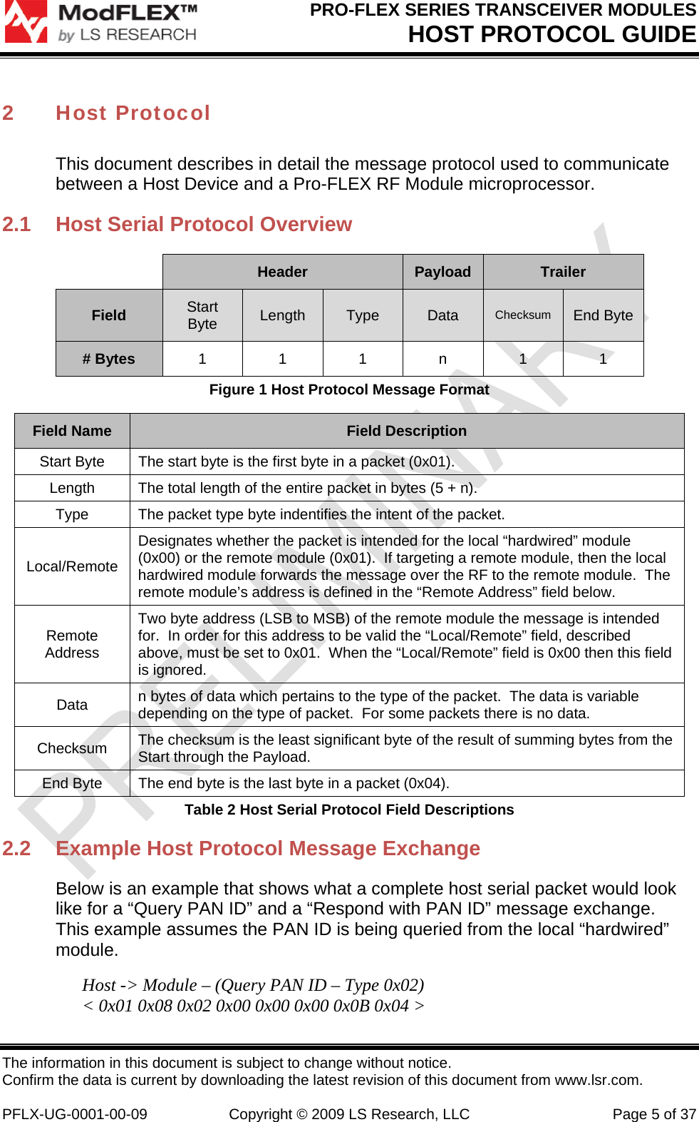
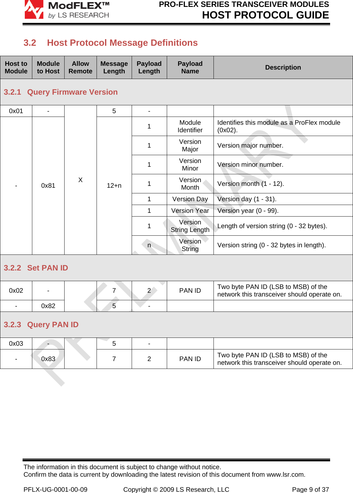
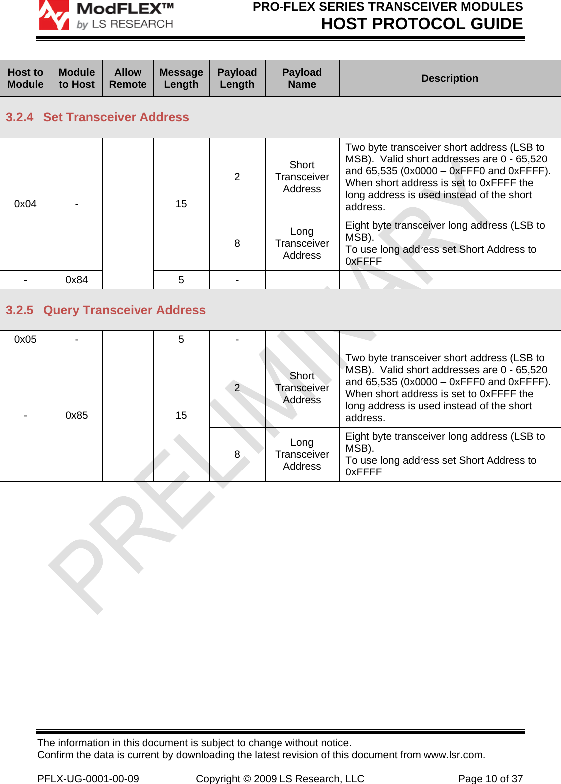
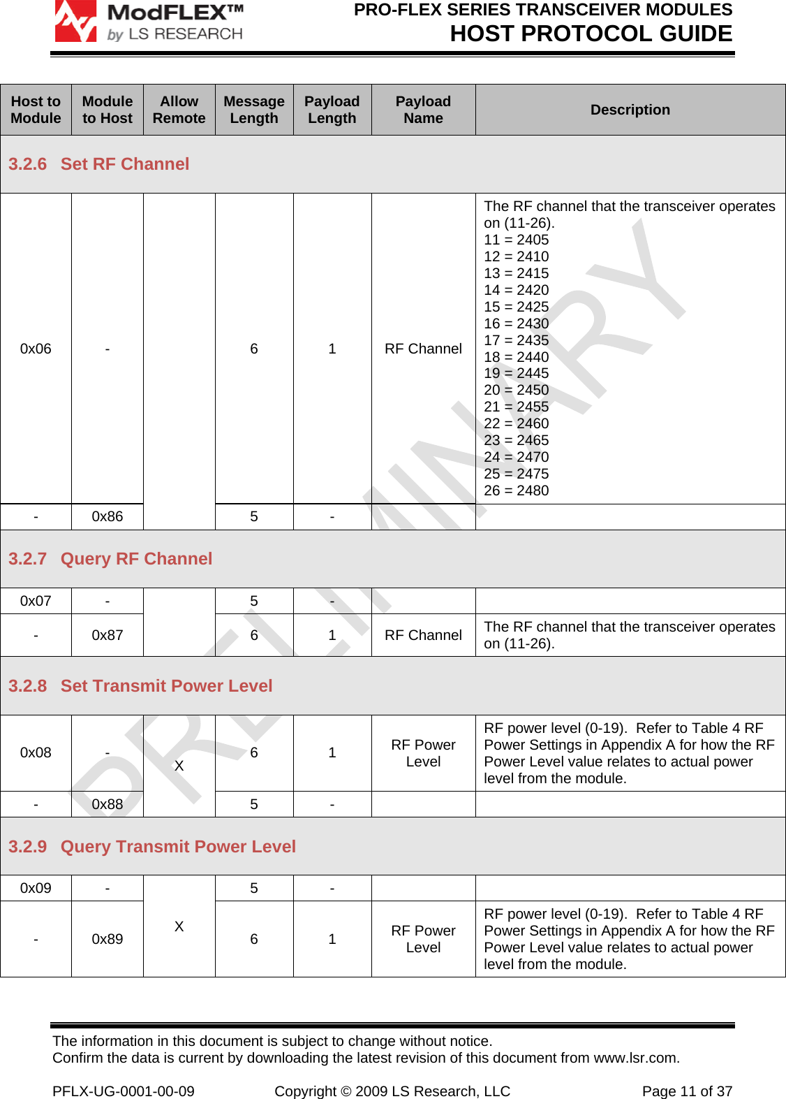
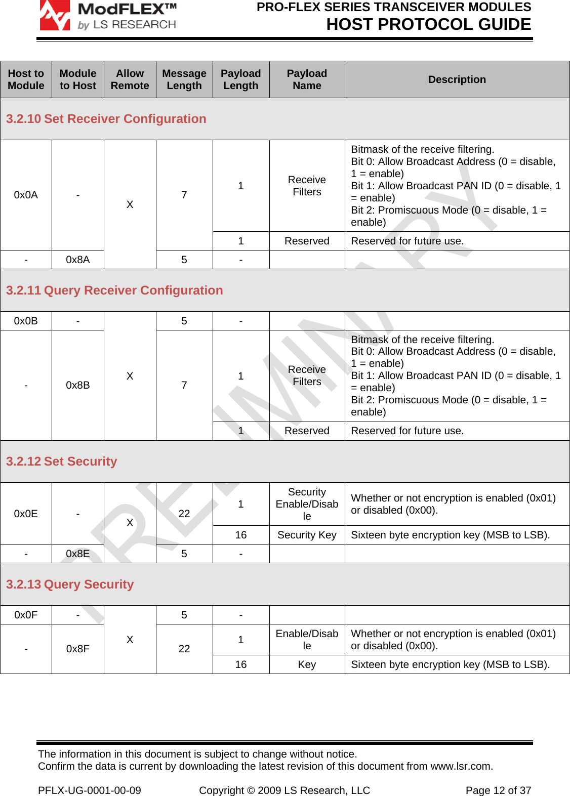
Laird Connectivity PROFLEX1 802.15.4 Transceiver Module User Manual PFLX UG 0001 00 10

LS Research, LLC 802.15.4 Transceiver Module PFLX UG 0001 00 10
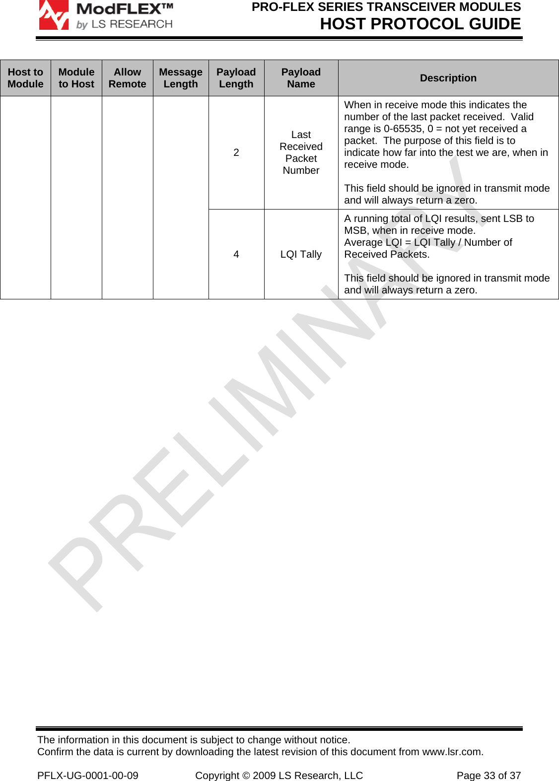
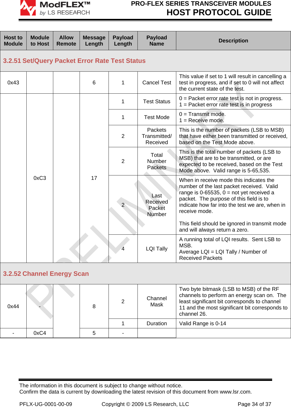
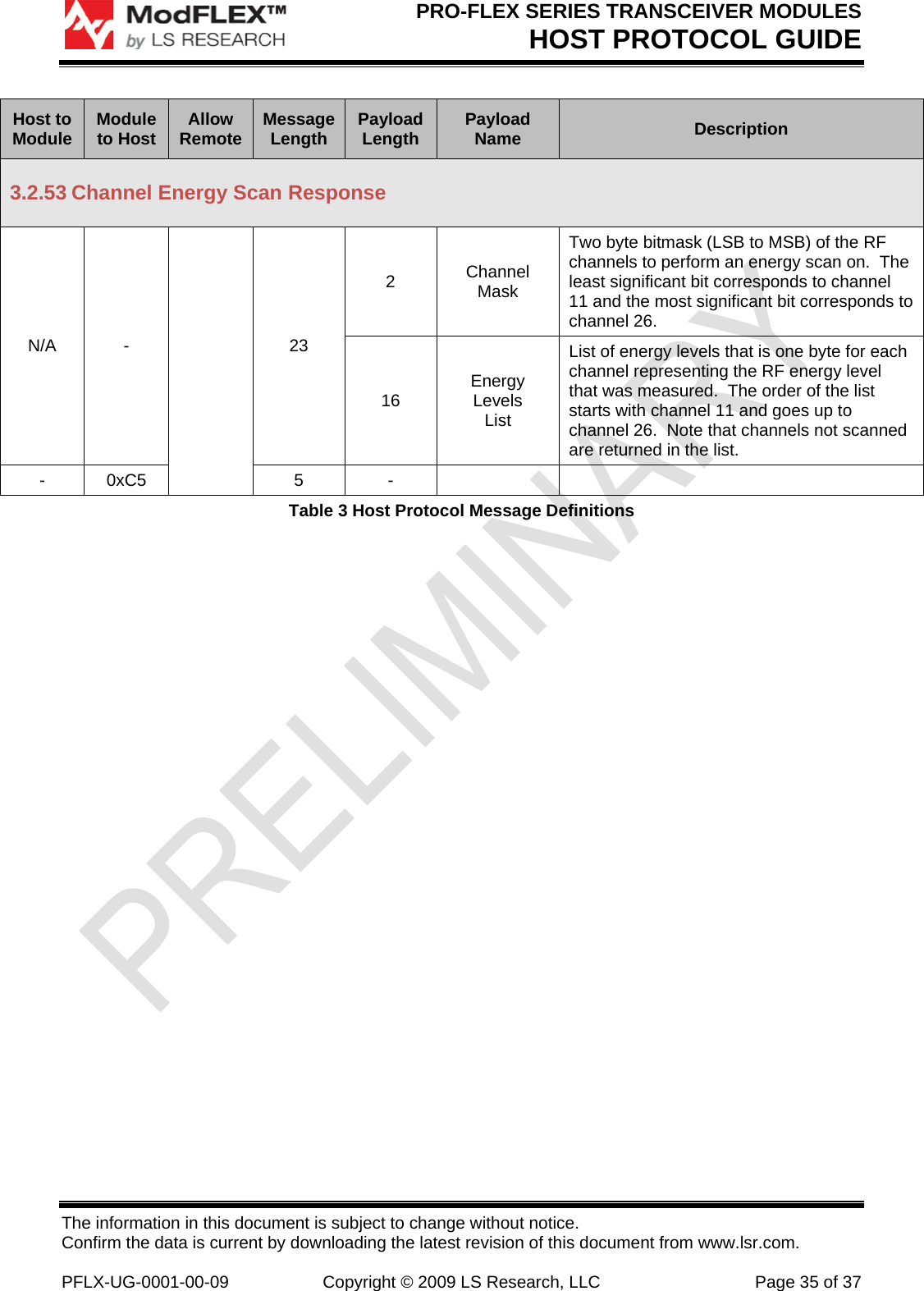
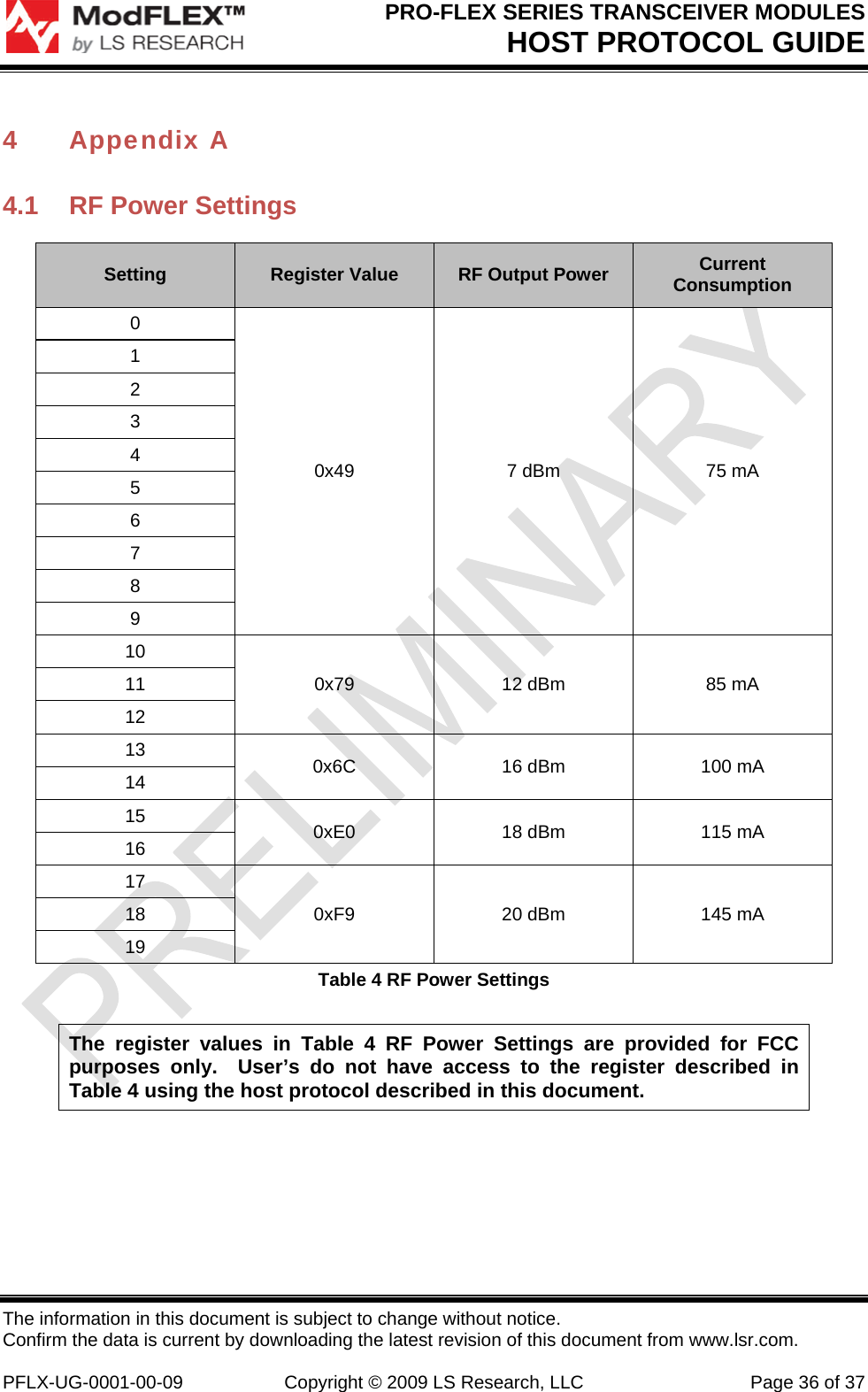
Contents

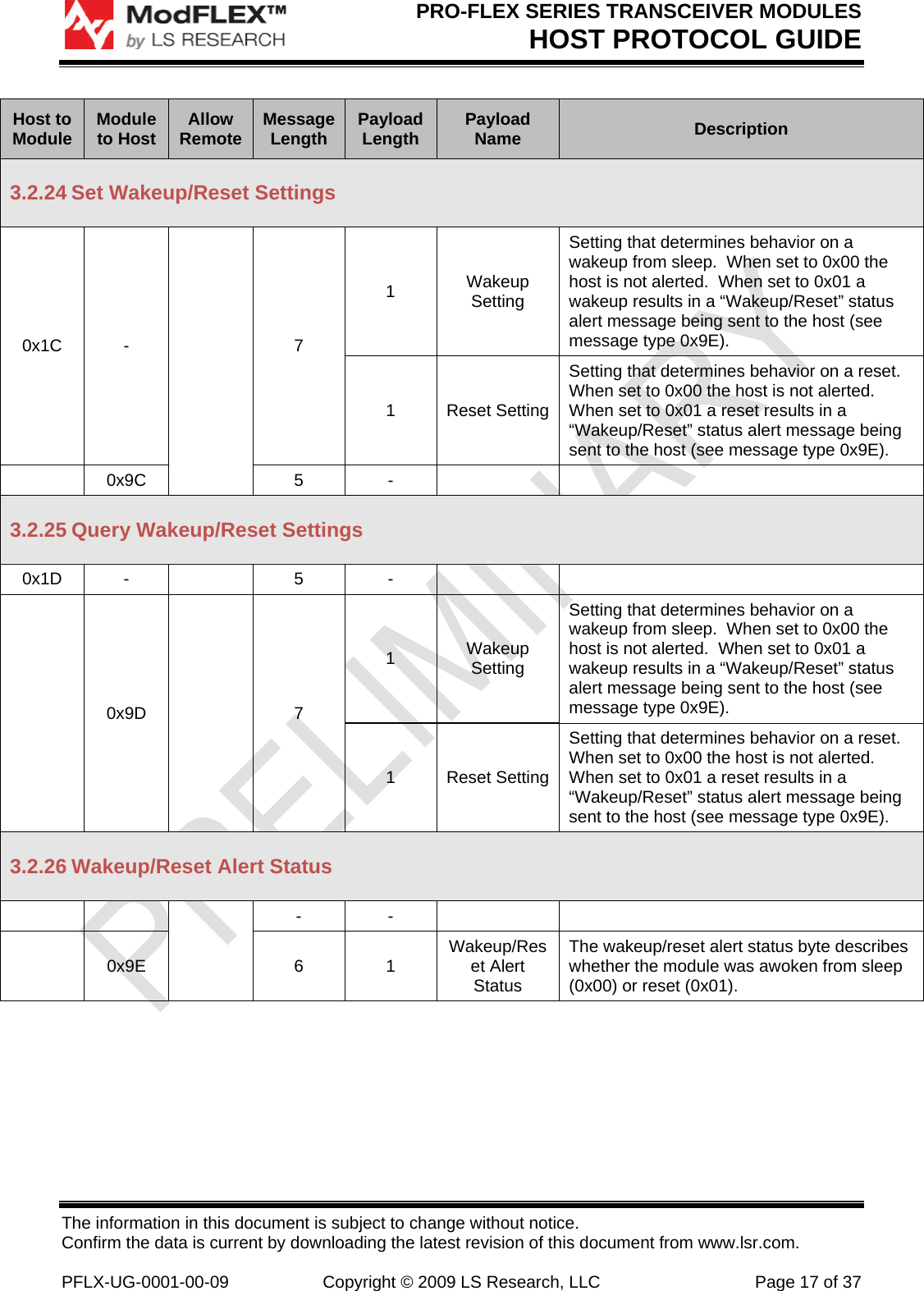
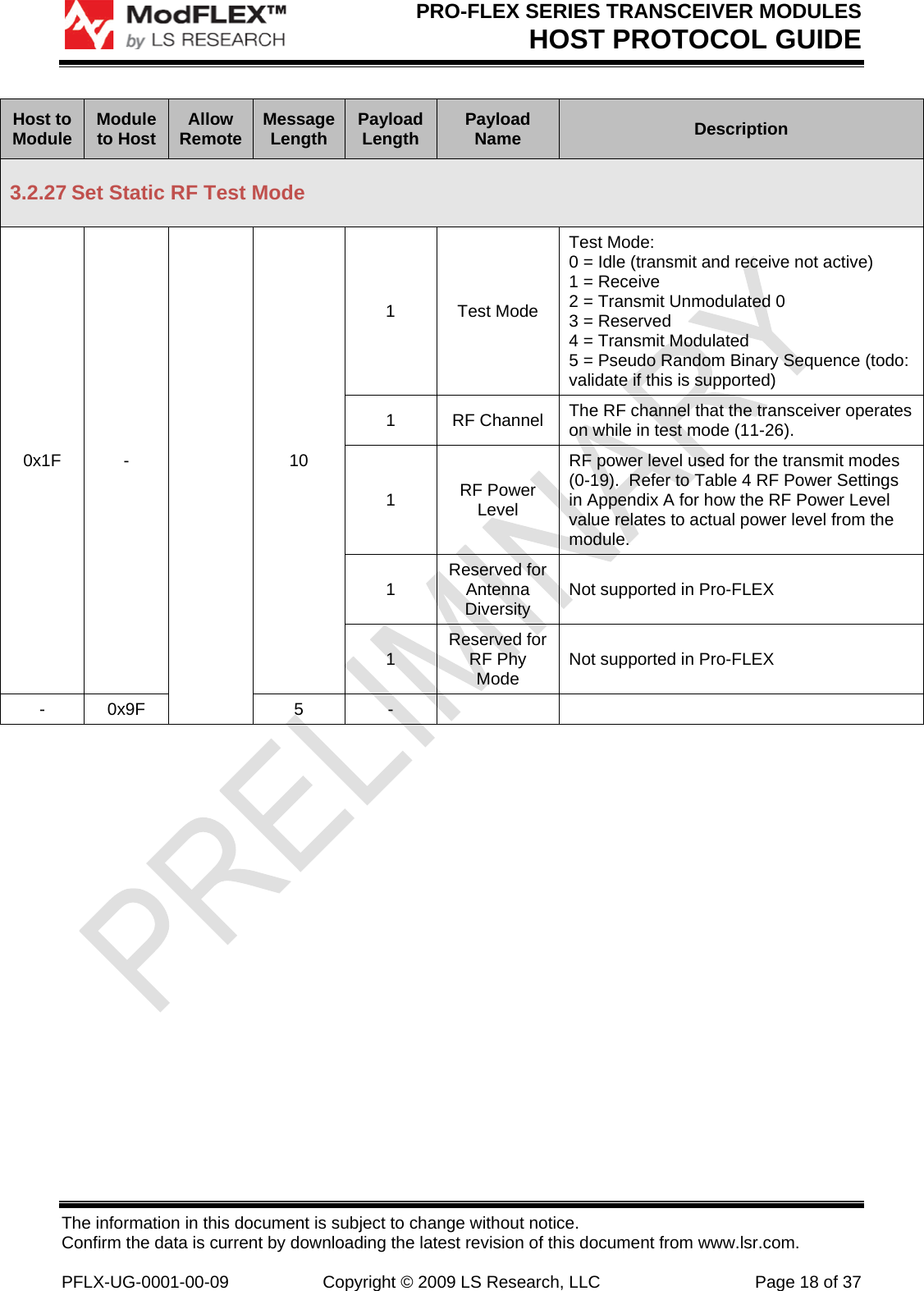
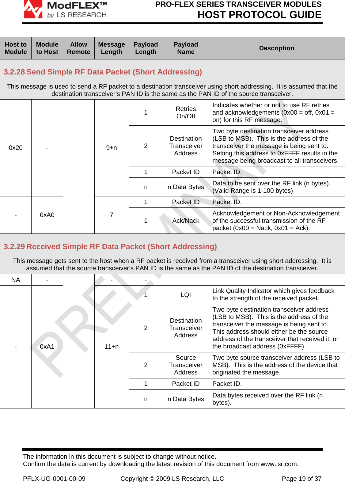
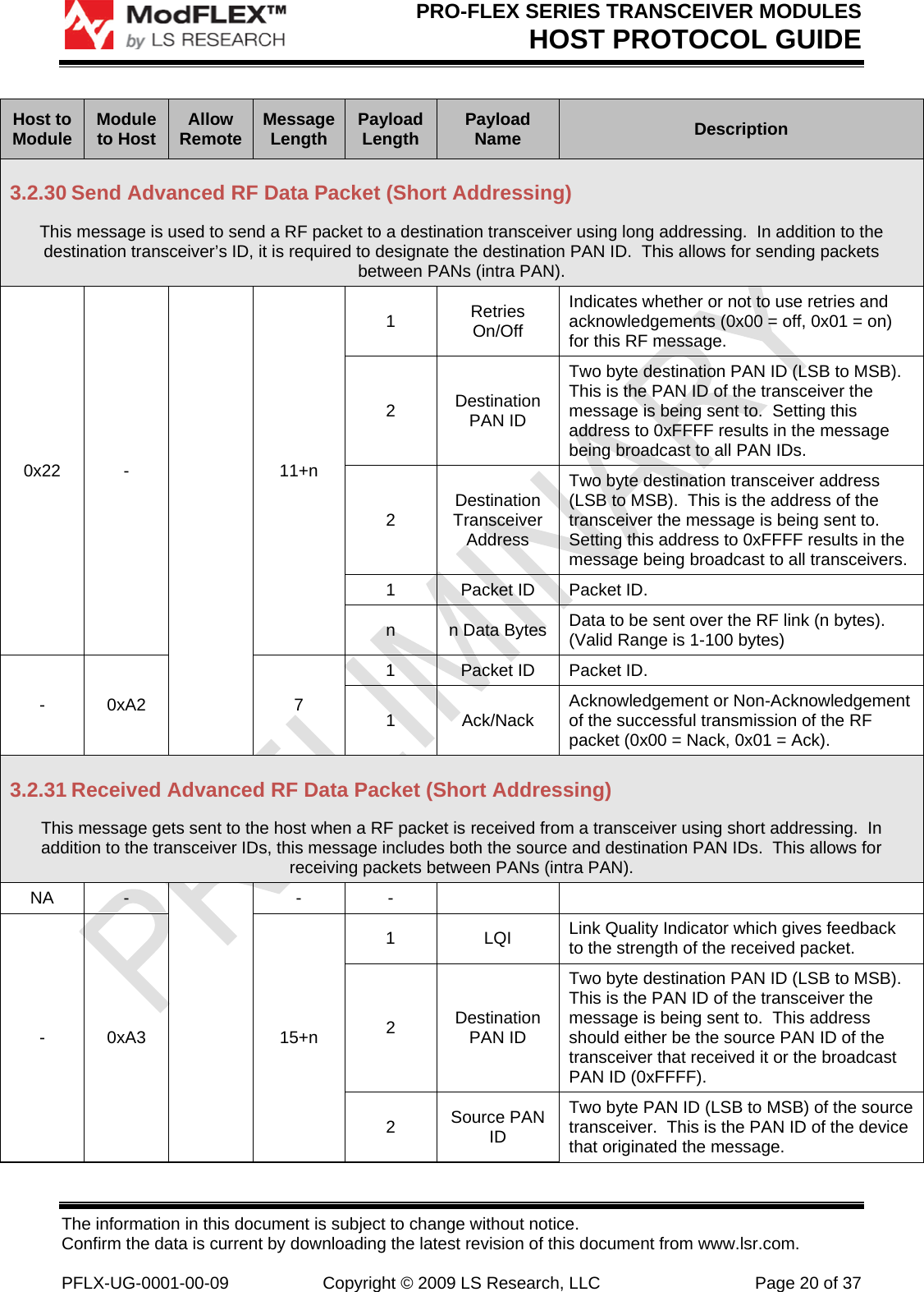
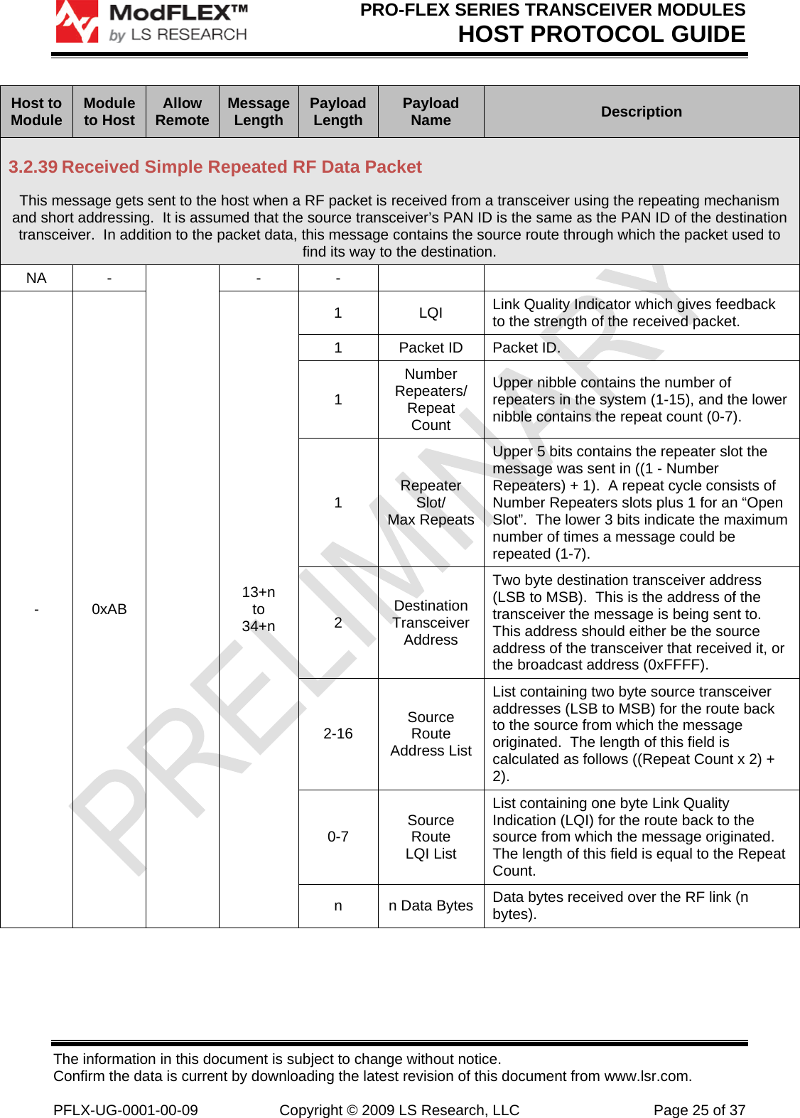
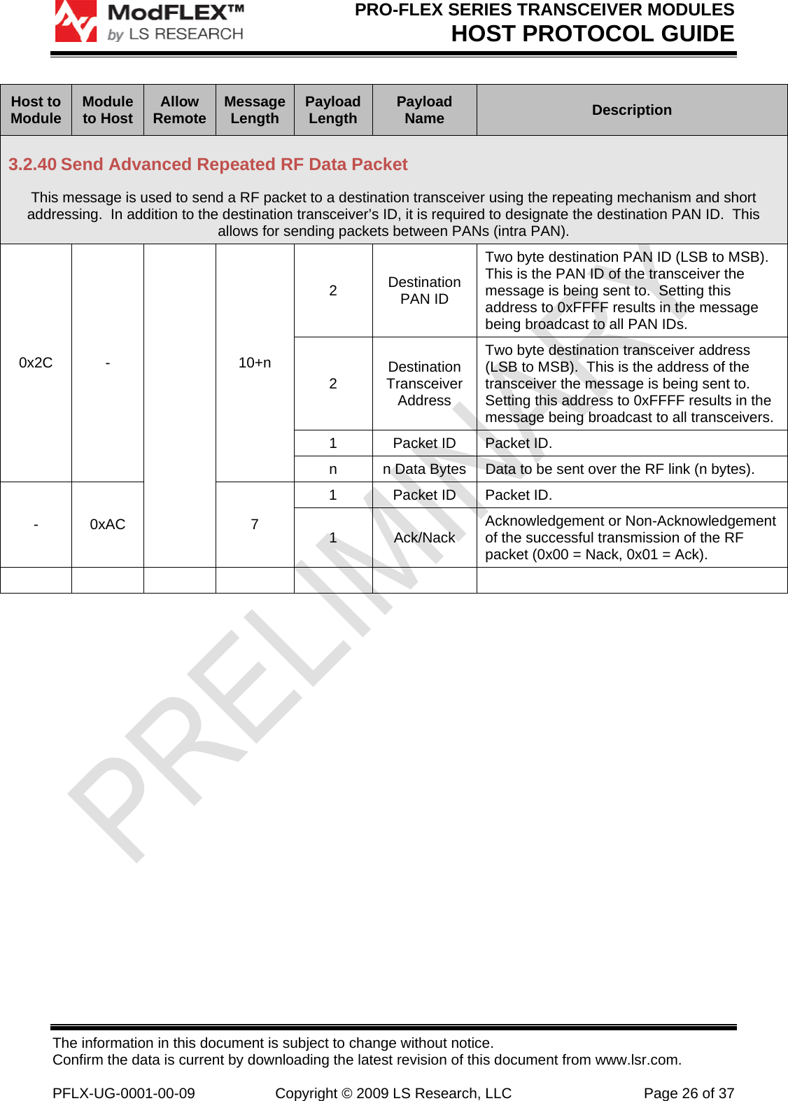
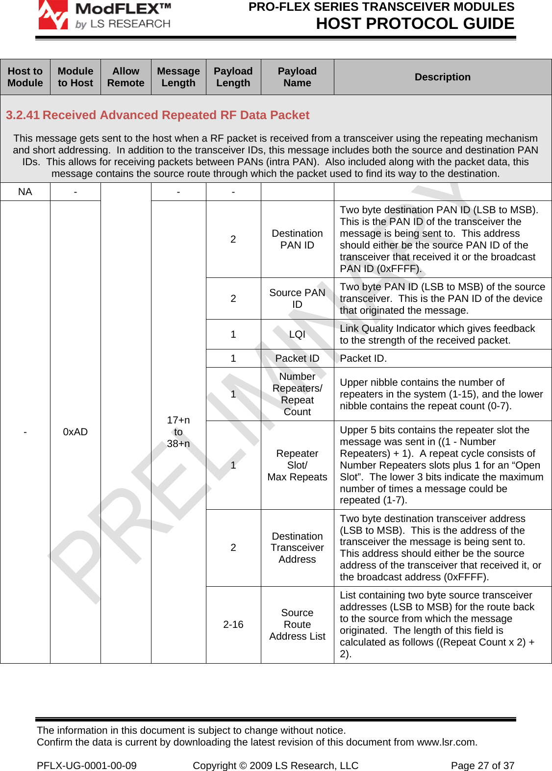
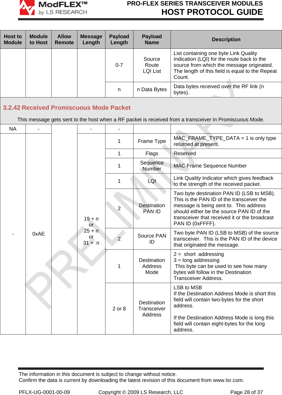
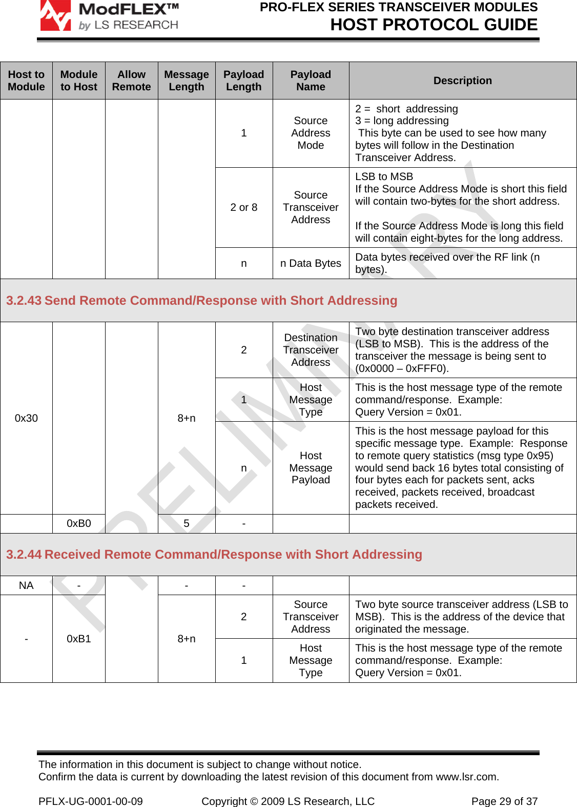
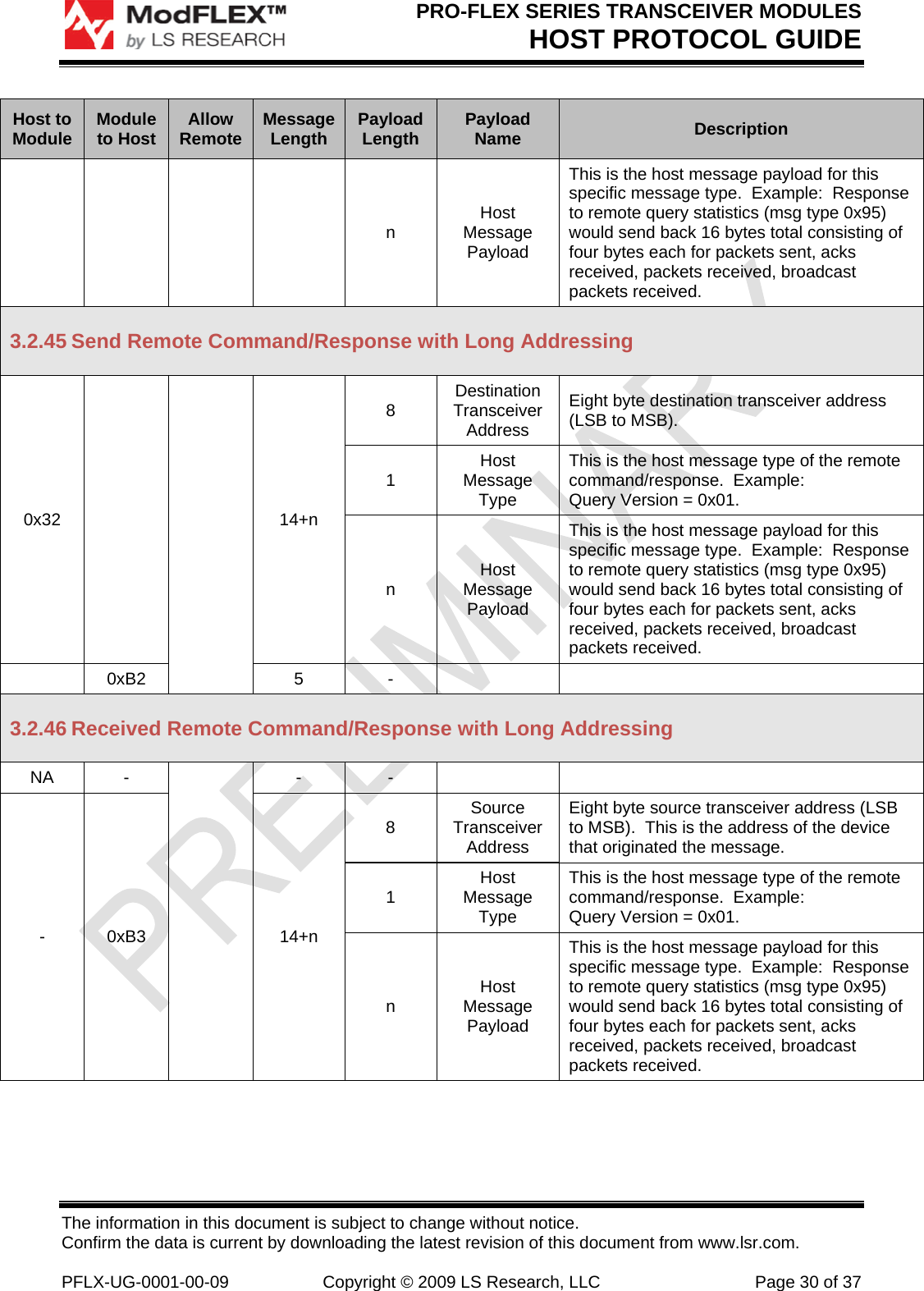
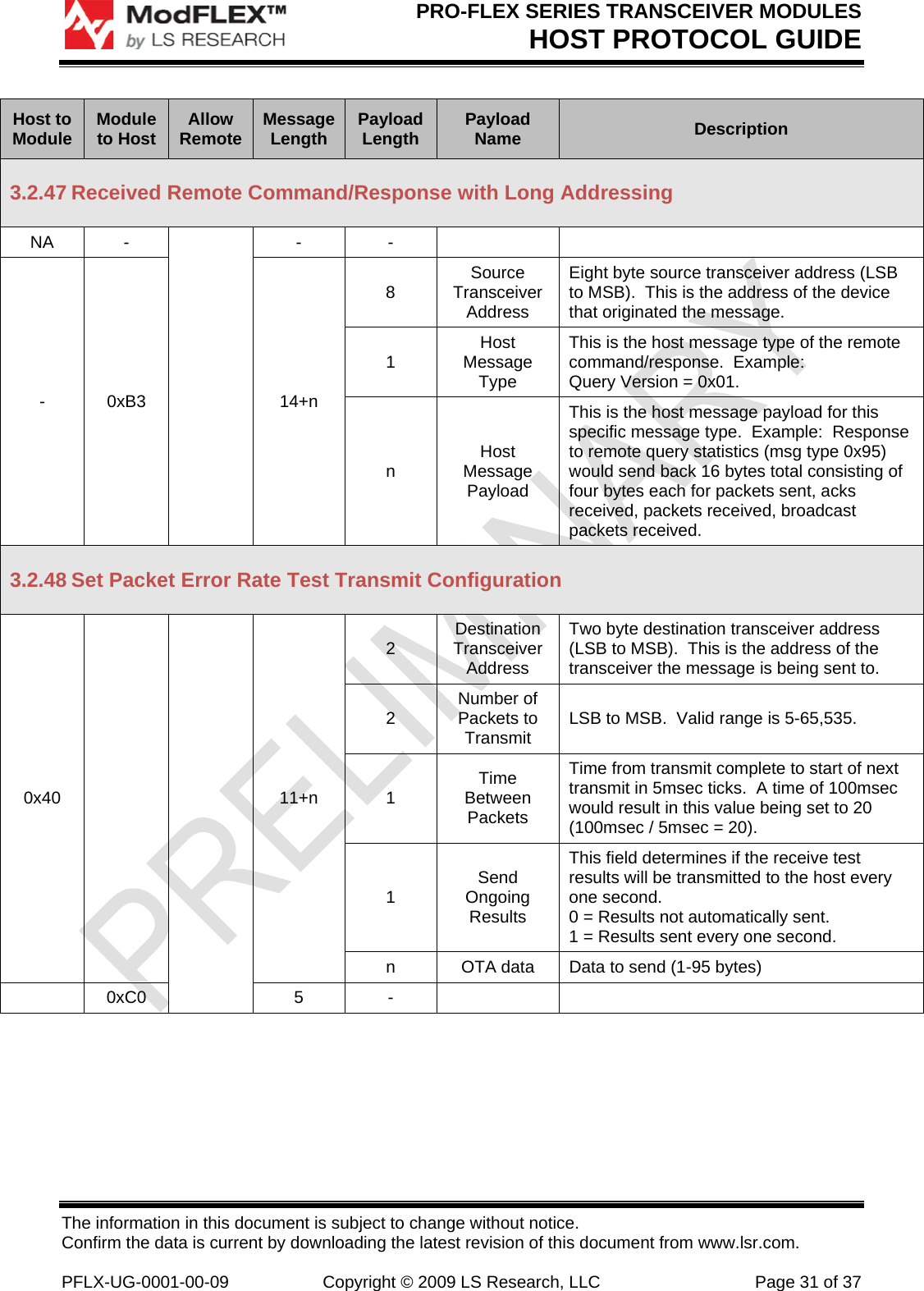
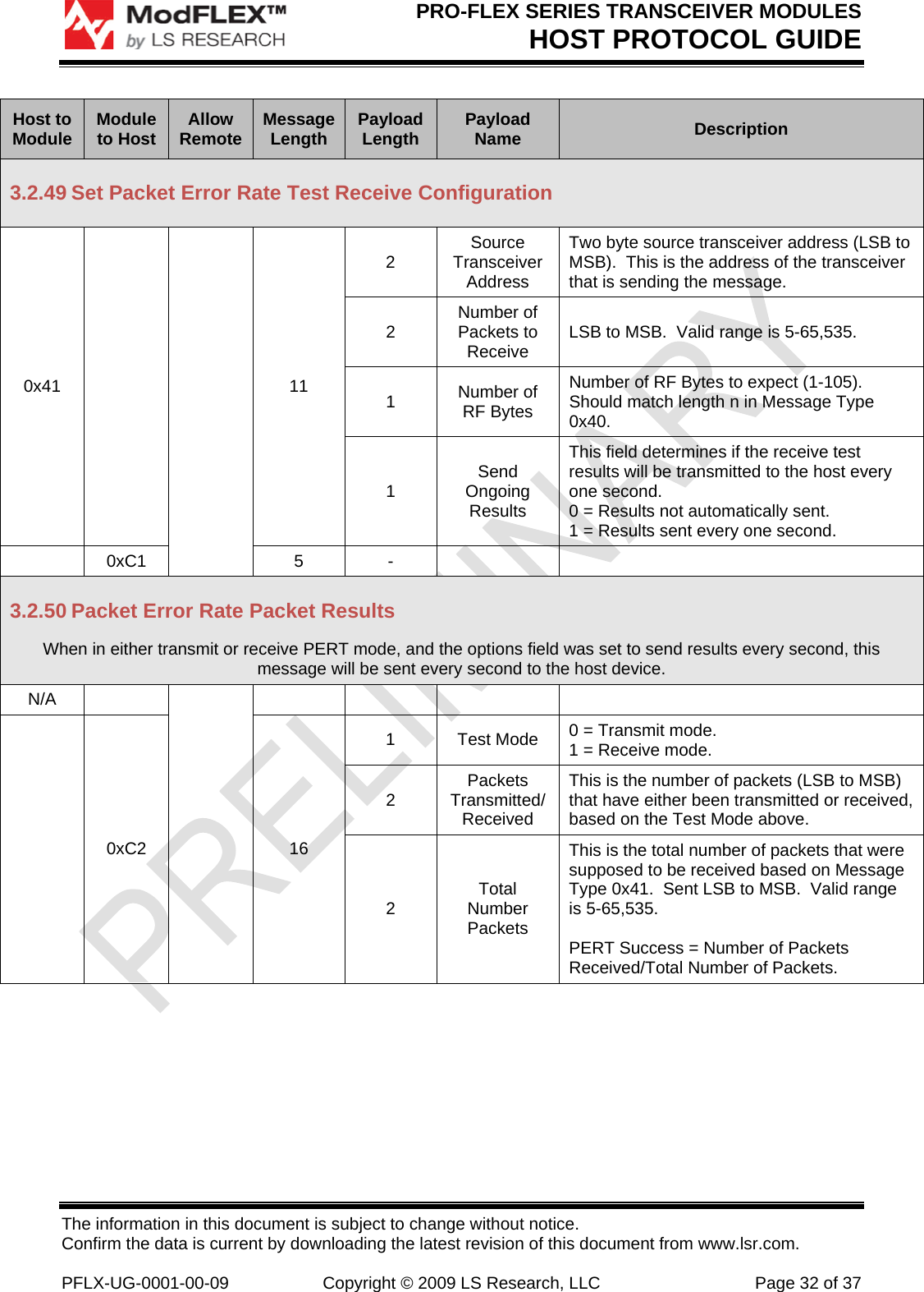
Manual Host Protocol Guide

 The information in this document is subject to change without notice. Confirm the data is current by downloading the latest revision of this document from www.lsr.com.  PFLX-UG-0001-00-04  Copyright © 2009 LS Research, LLC  Page 1 of 37 PRO-FLEX SERIES TRANSCEIVER MODULES Host Protocol Guide     Powered By     Last updated Tuesday, June 30, 2009
PRO-FLEX SERIES TRANSCEIVER MODULES HOST PROTOCOL GUIDE The information in this document is subject to change without notice. Confirm the data is current by downloading the latest revision of this document from www.lsr.com.  PFLX-UG-0001-00-09  Copyright © 2009 LS Research, LLC  Page 2 of 37 Table of Contents 1Introduction ..................................................................................................................... 41.1Purpose & Scope ....................................................................................................................... 41.2Audience .................................................................................................................................... 41.3Applicable Documents ............................................................................................................... 41.4Revision History ......................................................................................................................... 42Host Protocol ................................................................................................................... 52.1Host Serial Protocol Overview ................................................................................................... 52.2Example Host Protocol Message Exchange ............................................................................. 53Host Protocol Message Definitions ............................................................................... 73.1Host Protocol Field Descriptions ............................................................................................... 73.1.1Host to Module .................................................................................................................................. 73.1.2Module to Host .................................................................................................................................. 73.1.3Allow Remote .................................................................................................................................... 73.1.4Message Length ................................................................................................................................ 73.1.5Payload Field Length ......................................................................................................................... 83.1.6Payload Field Name .......................................................................................................................... 83.1.7Description......................................................................................................................................... 83.2Host Protocol Message Definitions ........................................................................................... 93.2.1Query Firmware Version .................................................................................................................... 93.2.2Set PAN ID ........................................................................................................................................ 93.2.3Query PAN ID .................................................................................................................................... 93.2.4Set Transceiver Address ................................................................................................................. 103.2.5Query Transceiver Address ............................................................................................................. 103.2.6Set RF Channel ............................................................................................................................... 113.2.7Query RF Channel ........................................................................................................................... 113.2.8Set Transmit Power Level ............................................................................................................... 113.2.9Query Transmit Power Level ........................................................................................................... 113.2.10Set Receiver Configuration .............................................................................................................. 123.2.11Query Receiver Configuration ......................................................................................................... 123.2.12Set Security ..................................................................................................................................... 123.2.13Query Security ................................................................................................................................. 123.2.14Set Basic RF Settings ...................................................................................................................... 133.2.15Query Basic RF Settings ................................................................................................................. 143.2.16Save Settings To Non-Volatile Memory ........................................................................................... 143.2.17Reset Request ................................................................................................................................. 153.2.18Query Supply Voltage ...................................................................................................................... 153.2.19Query Statistics ............................................................................................................................... 153.2.20Clear Statistics ................................................................................................................................. 153.2.21Set Low Power Mode ...................................................................................................................... 163.2.22Set Host Data Rate .......................................................................................................................... 163.2.23Reserved for Query On-Chip Temperature Sensor ......................................................................... 163.2.24Set Wakeup/Reset Settings ............................................................................................................. 173.2.25Query Wakeup/Reset Settings ........................................................................................................ 173.2.26Wakeup/Reset Alert Status ............................................................................................................. 173.2.27Set Static RF Test Mode ................................................................................................................. 18
PRO-FLEX SERIES TRANSCEIVER MODULES HOST PROTOCOL GUIDE The information in this document is subject to change without notice. Confirm the data is current by downloading the latest revision of this document from www.lsr.com.  PFLX-UG-0001-00-09  Copyright © 2009 LS Research, LLC  Page 3 of 37 3.2.28Send Simple RF Data Packet (Short Addressing) ........................................................................... 193.2.29Received Simple RF Data Packet (Short Addressing) ..................................................................... 193.2.30Send Advanced RF Data Packet (Short Addressing) ...................................................................... 203.2.31Received Advanced RF Data Packet (Short Addressing) ................................................................ 203.2.32Send Simple RF Data Packet (Long Addressing) ............................................................................ 213.2.33Received Simple RF Data Packet (Long Addressing) ..................................................................... 213.2.34Send Advanced RF Data Packet (Long Addressing) ....................................................................... 223.2.35Received Advanced RF Data Packet (Long Addressing) ................................................................ 233.2.36Set Repeater Configuration ............................................................................................................. 233.2.37Query Repeater Configuration ......................................................................................................... 243.2.38Send Simple Repeated RF Data Packet ......................................................................................... 243.2.39Received Simple Repeated RF Data Packet ................................................................................... 253.2.40Send Advanced Repeated RF Data Packet .................................................................................... 263.2.41Received Advanced Repeated RF Data Packet .............................................................................. 273.2.42Received Promiscuous Mode Packet .............................................................................................. 283.2.43Send Remote Command/Response with Short Addressing ............................................................ 293.2.44Received Remote Command/Response with Short Addressing ......................................................  293.2.45Send Remote Command/Response with Long Addressing ............................................................. 303.2.46Received Remote Command/Response with Long Addressing ...................................................... 303.2.47Received Remote Command/Response with Long Addressing ...................................................... 313.2.48Set Packet Error Rate Test Transmit Configuration ......................................................................... 313.2.49Set Packet Error Rate Test Receive Configuration .......................................................................... 323.2.50Packet Error Rate Packet Results ................................................................................................... 323.2.51Set/Query Packet Error Rate Test Status ........................................................................................ 343.2.52Channel Energy Scan ...................................................................................................................... 343.2.53Channel Energy Scan Response ..................................................................................................... 354Contacting LS Research ............................................................................................... 37
PRO-FLEX SERIES TRANSCEIVER MODULES HOST PROTOCOL GUIDE The information in this document is subject to change without notice. Confirm the data is current by downloading the latest revision of this document from www.lsr.com.  PFLX-UG-0001-00-09  Copyright © 2009 LS Research, LLC  Page 4 of 37 1 Introduction 1.1  Purpose & Scope The purpose of this document is to describe in detail the message protocol used to communicate between a Host Device and the RF Module microprocessor. 1.2 Audience This document is intended to be read by engineers and technical management.  A general knowledge of common engineering practices is assumed. 1.3 Applicable Documents The reader should be familiar with the following documentation:  ProFLEX-01 Datasheet 1.4 Revision History Date  Change Description  Revision  Initial release.  1.0             Table 1 Revision History
PRO-FLEX SERIES TRANSCEIVER MODULES HOST PROTOCOL GUIDE The information in this document is subject to change without notice. Confirm the data is current by downloading the latest revision of this document from www.lsr.com.  PFLX-UG-0001-00-09  Copyright © 2009 LS Research, LLC  Page 5 of 37 2 Host Protocol This document describes in detail the message protocol used to communicate between a Host Device and a Pro-FLEX RF Module microprocessor. 2.1  Host Serial Protocol Overview  Header  Payload  Trailer Field  Start Byte  Length  Type  Data Checksum End Byte # Bytes  1 1 1 n 1 1 Figure 1 Host Protocol Message Format Field Name  Field Description Start Byte  The start byte is the first byte in a packet (0x01). Length  The total length of the entire packet in bytes (5 + n). Type  The packet type byte indentifies the intent of the packet. Local/Remote Designates whether the packet is intended for the local “hardwired” module (0x00) or the remote module (0x01).  If targeting a remote module, then the local hardwired module forwards the message over the RF to the remote module.  The remote module’s address is defined in the “Remote Address” field below.  Remote Address Two byte address (LSB to MSB) of the remote module the message is intended for.  In order for this address to be valid the “Local/Remote” field, described above, must be set to 0x01.  When the “Local/Remote” field is 0x00 then this field is ignored. Data  n bytes of data which pertains to the type of the packet.  The data is variable depending on the type of packet.  For some packets there is no data. Checksum  The checksum is the least significant byte of the result of summing bytes from the Start through the Payload. End Byte  The end byte is the last byte in a packet (0x04). Table 2 Host Serial Protocol Field Descriptions 2.2  Example Host Protocol Message Exchange Below is an example that shows what a complete host serial packet would look like for a “Query PAN ID” and a “Respond with PAN ID” message exchange.  This example assumes the PAN ID is being queried from the local “hardwired” module. Host -> Module – (Query PAN ID – Type 0x02) < 0x01 0x08 0x02 0x00 0x00 0x00 0x0B 0x04 >
PRO-FLEX SERIES TRANSCEIVER MODULES HOST PROTOCOL GUIDE The information in this document is subject to change without notice. Confirm the data is current by downloading the latest revision of this document from www.lsr.com.  PFLX-UG-0001-00-09  Copyright © 2009 LS Research, LLC  Page 6 of 37 Module -> Host – (Respond with PAN ID – Type 0x82) < 0x01 0x0B 0x82 0x00 0x00 0x00 0x64 0x00 0xF2 0x04>
PRO-FLEX SERIES TRANSCEIVER MODULES HOST PROTOCOL GUIDE The information in this document is subject to change without notice. Confirm the data is current by downloading the latest revision of this document from www.lsr.com.  PFLX-UG-0001-00-09  Copyright © 2009 LS Research, LLC  Page 7 of 37 3 Host Protocol Message Definitions The information contained in this section is abbreviated and omits the header and trailer information which is common to all serial host messages. 3.1  Host Protocol Field Descriptions 3.1.1  Host to Module This field shows the message type for messages that get sent from the host device to the module, and are within the range of 0x01 through 0x7F. Host to Module  Module to Host  Allow Remote  Message Length  Payload Length  Payload Name  Description Figure 2 Host to Module 3.1.2 Module to Host This field shows the message type for messages that get sent from the module to the host device, and are within the range of 0x81 through 0x8F. Host to Module  Module to Host  Allow Remote  Message Length  Payload Length  Payload Name  Description Figure 3 Module to Host 3.1.3 Allow Remote This column will contain an “x” if the message supports being issued to a remote module.  A remote module is a module that is not physically hardwired to the host device that issues the message.  In general host messages can only be issued to a remote device that is on the same PAN ID and RF channel of the hardwired local module. Host to Module  Module to Host  Allow Remote  Message Length  Payload Length  Payload Name  Description Figure 4 Allow Remote 3.1.4 Message Length This column contains the length of the entire message, which consists of the header (6 bytes), payload, and trailer (2 bytes).  The minimum sized message is 8 bytes and occurs in messages that contain no payload.
PRO-FLEX SERIES TRANSCEIVER MODULES HOST PROTOCOL GUIDE The information in this document is subject to change without notice. Confirm the data is current by downloading the latest revision of this document from www.lsr.com.  PFLX-UG-0001-00-09  Copyright © 2009 LS Research, LLC  Page 8 of 37 Host to Module  Module to Host  Allow Remote  Message Length  Payload Length  Payload Name  Description Figure 5 Message Length 3.1.5  Payload Field Length This column lists the length in bytes of each payload field. Host to Module  Module to Host  Allow Remote  Message Length  Payload Length  Payload Name  Description Figure 6 Payload Field Length 3.1.6  Payload Field Name This column contains a list of the fields that are contained within each message. Host to Module  Module to Host  Allow Remote  Message Length  Payload Length  Payload Name  Description Figure 7 Payload Field Name 3.1.7 Description This column details what the message does or what is contained in the payload field. Host to Module  Module to Host  Allow Remote  Message Length  Payload Length  Payload Name  Description Figure 8 Description
PRO-FLEX SERIES TRANSCEIVER MODULES HOST PROTOCOL GUIDE The information in this document is subject to change without notice. Confirm the data is current by downloading the latest revision of this document from www.lsr.com.  PFLX-UG-0001-00-09  Copyright © 2009 LS Research, LLC  Page 9 of 37 3.2  Host Protocol Message Definitions Host to Module  Module to Host  Allow Remote  Message Length  Payload Length  Payload Name  Description 3.2.1  Query Firmware Version 0x01 - X 5 -    - 0x81  12+n 1  Module Identifier  Identifies this module as a ProFlex module (0x02). 1  Version Major  Version major number. 1  Version Minor  Version minor number. 1  Version Month  Version month (1 - 12). 1  Version Day  Version day (1 - 31). 1  Version Year  Version year (0 - 99). 1  Version String Length  Length of version string (0 - 32 bytes). n  Version String  Version string (0 - 32 bytes in length). 3.2.2  Set PAN ID 0x02 -   7 2 PAN ID Two byte PAN ID (LSB to MSB) of the network this transceiver should operate on. - 0x82  5  -     3.2.3  Query PAN ID 0x03 -  5 -    - 0x83  7  2  PAN ID Two byte PAN ID (LSB to MSB) of the network this transceiver should operate on.
PRO-FLEX SERIES TRANSCEIVER MODULES HOST PROTOCOL GUIDE The information in this document is subject to change without notice. Confirm the data is current by downloading the latest revision of this document from www.lsr.com.  PFLX-UG-0001-00-09  Copyright © 2009 LS Research, LLC  Page 10 of 37 Host to Module  Module to Host  Allow Remote  Message Length  Payload Length  Payload Name  Description 3.2.4  Set Transceiver Address 0x04 -   15 2  Short Transceiver Address Two byte transceiver short address (LSB to MSB).  Valid short addresses are 0 - 65,520 and 65,535 (0x0000 – 0xFFF0 and 0xFFFF).  When short address is set to 0xFFFF the long address is used instead of the short address. 8  Long Transceiver Address Eight byte transceiver long address (LSB to MSB). To use long address set Short Address to 0xFFFF - 0x84  5  -     3.2.5  Query Transceiver Address 0x05 -  5 -    - 0x85  15 2  Short Transceiver Address Two byte transceiver short address (LSB to MSB).  Valid short addresses are 0 - 65,520 and 65,535 (0x0000 – 0xFFF0 and 0xFFFF).  When short address is set to 0xFFFF the long address is used instead of the short address. 8  Long Transceiver Address Eight byte transceiver long address (LSB to MSB). To use long address set Short Address to 0xFFFF
PRO-FLEX SERIES TRANSCEIVER MODULES HOST PROTOCOL GUIDE The information in this document is subject to change without notice. Confirm the data is current by downloading the latest revision of this document from www.lsr.com.  PFLX-UG-0001-00-09  Copyright © 2009 LS Research, LLC  Page 11 of 37 Host to Module  Module to Host  Allow Remote  Message Length  Payload Length  Payload Name  Description 3.2.6  Set RF Channel 0x06 -   6 1 RF Channel The RF channel that the transceiver operates on (11-26). 11 = 2405 12 = 2410 13 = 2415 14 = 2420 15 = 2425 16 = 2430 17 = 2435 18 = 2440 19 = 2445 20 = 2450 21 = 2455 22 = 2460 23 = 2465 24 = 2470 25 = 2475 26 = 2480 - 0x86  5  -     3.2.7 Query RF Channel 0x07 -  5 -    - 0x87  6  1 RF Channel The RF channel that the transceiver operates on (11-26). 3.2.8  Set Transmit Power Level 0x08 -  X  6 1 RF Power Level RF power level (0-19).  Refer to Table 4 RF Power Settings in Appendix A for how the RF Power Level value relates to actual power level from the module. - 0x88  5  -     3.2.9  Query Transmit Power Level 0x09 - X 5 -    - 0x89  6  1 RF Power Level RF power level (0-19).  Refer to Table 4 RF Power Settings in Appendix A for how the RF Power Level value relates to actual power level from the module.
PRO-FLEX SERIES TRANSCEIVER MODULES HOST PROTOCOL GUIDE The information in this document is subject to change without notice. Confirm the data is current by downloading the latest revision of this document from www.lsr.com.  PFLX-UG-0001-00-09  Copyright © 2009 LS Research, LLC  Page 12 of 37 Host to Module  Module to Host  Allow Remote  Message Length  Payload Length  Payload Name  Description 3.2.10 Set Receiver Configuration 0x0A -  X  7  1  Receive Filters Bitmask of the receive filtering. Bit 0: Allow Broadcast Address (0 = disable, 1 = enable) Bit 1: Allow Broadcast PAN ID (0 = disable, 1 = enable) Bit 2: Promiscuous Mode (0 = disable, 1 = enable) 1  Reserved  Reserved for future use. - 0x8A  5  -     3.2.11 Query Receiver Configuration 0x0B - X 5 -    - 0x8B  7  1  Receive Filters Bitmask of the receive filtering. Bit 0: Allow Broadcast Address (0 = disable, 1 = enable) Bit 1: Allow Broadcast PAN ID (0 = disable, 1 = enable) Bit 2: Promiscuous Mode (0 = disable, 1 = enable) 1  Reserved  Reserved for future use. 3.2.12 Set Security 0x0E -  X  22  1  Security Enable/Disable Whether or not encryption is enabled (0x01) or disabled (0x00). 16  Security Key  Sixteen byte encryption key (MSB to LSB). - 0x8E  5  -     3.2.13 Query Security 0x0F - X 5 -    - 0x8F  22  1  Enable/Disable  Whether or not encryption is enabled (0x01) or disabled (0x00). 16  Key  Sixteen byte encryption key (MSB to LSB).
PRO-FLEX SERIES TRANSCEIVER MODULES HOST PROTOCOL GUIDE The information in this document is subject to change without notice. Confirm the data is current by downloading the latest revision of this document from www.lsr.com.  PFLX-UG-0001-00-09  Copyright © 2009 LS Research, LLC  Page 13 of 37 Host to Module  Module to Host  Allow Remote  Message Length  Payload Length  Payload Name  Description 3.2.14 Set Basic RF Settings 0x10 -   39 2 PAN ID Two byte PAN ID (LSB to MSB) of the network this transceiver should operate on. 2  Short Transceiver Address Two byte transceiver short address (LSB to MSB).  Valid short addresses are 0 - 65,520 and 65,535 (0x0000 – 0xFFF0 and 0xFFFF).  When short address is set to 0xFFFF the long address is used instead of the short address. 8  Long Transceiver Address Eight byte transceiver long address (LSB to MSB). To use long address set Short Address to 0xFFFF 1 RF Channel The RF channel that the transceiver operates on (11-26). 1  RF Power Level RF power level (0-19).  Refer to Table 4 RF Power Settings in Appendix A for how the RF Power Level value relates to actual power level from the module. 1  Receive Filters Bitmask of the receive filtering. Bit 0: Allow Broadcast Address (0 = disable, 1 = enable) Bit 1: Allow Broadcast PAN ID (0 = disable, 1 = enable) Bit 2: Promiscuous Mode (0 = disable, 1 = enable) 1  Reserved  Reserved for future use. 1  Reserved  Reserved for future use. 1  Security Enable/Disable Whether or not encryption is enabled (0x01) or disabled (0x00). 16  Security Key  Sixteen byte encryption key (MSB to LSB). - 0x90  5  -
PRO-FLEX SERIES TRANSCEIVER MODULES HOST PROTOCOL GUIDE The information in this document is subject to change without notice. Confirm the data is current by downloading the latest revision of this document from www.lsr.com.  PFLX-UG-0001-00-09  Copyright © 2009 LS Research, LLC  Page 14 of 37 Host to Module  Module to Host  Allow Remote  Message Length  Payload Length  Payload Name  Description 3.2.15 Query Basic RF Settings 0x11 -  5 -    - 0x91  39 2 PAN ID Two byte PAN ID (LSB to MSB) of the network this transceiver should operate on. 2  Short Transceiver Address Two byte transceiver short address (LSB to MSB).  Valid short addresses are 0 - 65,520 and 65,535 (0x0000 – 0xFFF0 and 0xFFFF).  When short address is set to 0xFFFF the long address is used instead of the short address. 8  Long Transceiver Address Eight byte transceiver long address (LSB to MSB). To use long address set Short Address to 0xFFFF 1 RF Channel The RF channel that the transceiver operates on (1-10). 1  RF Power Level RF power level (0-19).  Refer to Table 4 RF Power Settings in Appendix A for how the RF Power Level value relates to actual power level from the module. 1  Receive Filters Bitmask of the receive filtering. Bit 0: Allow Broadcast Address (0 = disable, 1 = enable) Bit 1: Allow Broadcast PAN ID (0 = disable, 1 = enable) Bit 2: Promiscuous Mode (0 = disable, 1 = enable) 1  Reserved  Reserved for future use. 1  Reserved for Antenna Diversity  Not supported in Pro-FLEX 1  Security Enable/Disable Whether or not encryption is enabled (0x01) or disabled (0x00). 16  Security Key  Sixteen byte encryption key (MSB to LSB). 3.2.16 Save Settings To Non-Volatile Memory 0x12 -  X  5 -    - 0x92  5  -
PRO-FLEX SERIES TRANSCEIVER MODULES HOST PROTOCOL GUIDE The information in this document is subject to change without notice. Confirm the data is current by downloading the latest revision of this document from www.lsr.com.  PFLX-UG-0001-00-09  Copyright © 2009 LS Research, LLC  Page 15 of 37 Host to Module  Module to Host  Allow Remote  Message Length  Payload Length  Payload Name  Description 3.2.17 Reset Request 0x13 -    5  -     - 0x93    5  -     3.2.18 Query Supply Voltage 0x14 - X 5 -    - 0x94  8 2  Supply ADC Reading The supply voltage ADC reading (LSB to MSB).  The supply voltage can be determined by the following formula: Supply Voltage = ((Supply ADC Reading x Voltage Reference ) / 204750). Example: ADC Reading = 2750 Voltage Reference = 245 Supply Voltage = ( (2750 * 245) / 20,4750) Supply Voltage = 3.36V 1  Voltage Reference The Voltage Reference used in the measurement multiplied by 100.  For example the 1.47V reference will be passed as 147. 3.2.19 Query Statistics 0x15 - X 5 -    - 0x95  21 4 Packets Sent Four byte value for RF packets sent (LSB to MSB). 4  Acks Received  Four byte value for RF acknowledgements received (LSB to MSB). 4  Packets Received  Four byte value for RF packets received (LSB to MSB). 4  Broadcast Packets Received Four byte value for RF broadcast packets received (LSB to MSB). 3.2.20 Clear Statistics 0x16 -    5  -     - 0x96    5  -
PRO-FLEX SERIES TRANSCEIVER MODULES HOST PROTOCOL GUIDE The information in this document is subject to change without notice. Confirm the data is current by downloading the latest revision of this document from www.lsr.com.  PFLX-UG-0001-00-09  Copyright © 2009 LS Research, LLC  Page 16 of 37 Host to Module  Module to Host  Allow Remote  Message Length  Payload Length  Payload Name  Description 3.2.21 Set Low Power Mode 0x17 -   6  1  Reserved  Reserved for future use. - 0x97  5  -     3.2.22 Set Host Data Rate 0x18 -   6 1 Baud Rate Serial baud rate setting. 0 = 1,200, 1 = 2,400, 2 = 4,800, 3 = 9,600, 4 = 19,200, 5 = 38,400, 6 = 57,600, 7 = 115,200, 8 = 230,400, 9 = 460,800, 10 = 921,600. - 0x98  5  -     3.2.23 Reserved for Query On-Chip Temperature Sensor 0x1B - X 5 -    - 0x9B  7  2  Supply ADC Reading The supply voltage ADC reading (LSB to MSB).  The temperature can be determined by the following formula: TEMP °C = (V – 0.894)/0.00366 where V = (ADC Reading * 1.47)/4095  Example: ADC Reading = 2800 Temp °C = ( (  ((2800*1.47)/4095 )-0.894) / 0.00366)  Temp °C = 30.4
PRO-FLEX SERIES TRANSCEIVER MODULES HOST PROTOCOL GUIDE The information in this document is subject to change without notice. Confirm the data is current by downloading the latest revision of this document from www.lsr.com.  PFLX-UG-0001-00-09  Copyright © 2009 LS Research, LLC  Page 17 of 37 Host to Module  Module to Host  Allow Remote  Message Length  Payload Length  Payload Name  Description 3.2.24 Set Wakeup/Reset Settings 0x1C -   7 1  Wakeup Setting Setting that determines behavior on a wakeup from sleep.  When set to 0x00 the host is not alerted.  When set to 0x01 a wakeup results in a “Wakeup/Reset” status alert message being sent to the host (see message type 0x9E). 1 Reset Setting Setting that determines behavior on a reset.  When set to 0x00 the host is not alerted.  When set to 0x01 a reset results in a “Wakeup/Reset” status alert message being sent to the host (see message type 0x9E).  0x9C  5  -     3.2.25 Query Wakeup/Reset Settings 0x1D -    5  -      0x9D   7 1  Wakeup Setting Setting that determines behavior on a wakeup from sleep.  When set to 0x00 the host is not alerted.  When set to 0x01 a wakeup results in a “Wakeup/Reset” status alert message being sent to the host (see message type 0x9E). 1 Reset Setting Setting that determines behavior on a reset.  When set to 0x00 the host is not alerted.  When set to 0x01 a reset results in a “Wakeup/Reset” status alert message being sent to the host (see message type 0x9E). 3.2.26 Wakeup/Reset Alert Status    - -     0x9E  6  1 Wakeup/Reset Alert Status The wakeup/reset alert status byte describes whether the module was awoken from sleep (0x00) or reset (0x01).
PRO-FLEX SERIES TRANSCEIVER MODULES HOST PROTOCOL GUIDE The information in this document is subject to change without notice. Confirm the data is current by downloading the latest revision of this document from www.lsr.com.  PFLX-UG-0001-00-09  Copyright © 2009 LS Research, LLC  Page 18 of 37 Host to Module  Module to Host  Allow Remote  Message Length  Payload Length  Payload Name  Description 3.2.27 Set Static RF Test Mode 0x1F -   10 1 Test Mode Test Mode: 0 = Idle (transmit and receive not active) 1 = Receive 2 = Transmit Unmodulated 0 3 = Reserved 4 = Transmit Modulated 5 = Pseudo Random Binary Sequence (todo: validate if this is supported) 1 RF Channel The RF channel that the transceiver operates on while in test mode (11-26). 1  RF Power Level RF power level used for the transmit modes (0-19).  Refer to Table 4 RF Power Settings in Appendix A for how the RF Power Level value relates to actual power level from the module. 1  Reserved for Antenna Diversity  Not supported in Pro-FLEX 1  Reserved for RF Phy Mode  Not supported in Pro-FLEX - 0x9F  5  -
PRO-FLEX SERIES TRANSCEIVER MODULES HOST PROTOCOL GUIDE The information in this document is subject to change without notice. Confirm the data is current by downloading the latest revision of this document from www.lsr.com.  PFLX-UG-0001-00-09  Copyright © 2009 LS Research, LLC  Page 19 of 37 Host to Module  Module to Host  Allow Remote  Message Length  Payload Length  Payload Name  Description 3.2.28 Send Simple RF Data Packet (Short Addressing) This message is used to send a RF packet to a destination transceiver using short addressing.  It is assumed that the destination transceiver’s PAN ID is the same as the PAN ID of the source transceiver. 0x20 -  9+n 1  Retries On/Off Indicates whether or not to use RF retries and acknowledgements (0x00 = off, 0x01 = on) for this RF message. 2  Destination Transceiver Address Two byte destination transceiver address (LSB to MSB).  This is the address of the transceiver the message is being sent to.  Setting this address to 0xFFFF results in the message being broadcast to all transceivers. 1  Packet ID  Packet ID. n  n Data Bytes  Data to be sent over the RF link (n bytes).  (Valid Range is 1-100 bytes) - 0xA0  7 1  Packet ID  Packet ID. 1 Ack/Nack Acknowledgement or Non-Acknowledgement of the successful transmission of the RF packet (0x00 = Nack, 0x01 = Ack). 3.2.29 Received Simple RF Data Packet (Short Addressing) This message gets sent to the host when a RF packet is received from a transceiver using short addressing.  It is assumed that the source transceiver’s PAN ID is the same as the PAN ID of the destination transceiver. NA -  - -    - 0xA1  11+n 1 LQI Link Quality Indicator which gives feedback to the strength of the received packet.  2  Destination Transceiver Address Two byte destination transceiver address (LSB to MSB).  This is the address of the transceiver the message is being sent to.  This address should either be the source address of the transceiver that received it, or the broadcast address (0xFFFF). 2  Source Transceiver Address Two byte source transceiver address (LSB to MSB).  This is the address of the device that originated the message. 1  Packet ID  Packet ID. n  n Data Bytes  Data bytes received over the RF link (n bytes).
PRO-FLEX SERIES TRANSCEIVER MODULES HOST PROTOCOL GUIDE The information in this document is subject to change without notice. Confirm the data is current by downloading the latest revision of this document from www.lsr.com.  PFLX-UG-0001-00-09  Copyright © 2009 LS Research, LLC  Page 20 of 37 Host to Module  Module to Host  Allow Remote  Message Length  Payload Length  Payload Name  Description 3.2.30 Send Advanced RF Data Packet (Short Addressing) This message is used to send a RF packet to a destination transceiver using long addressing.  In addition to the destination transceiver’s ID, it is required to designate the destination PAN ID.  This allows for sending packets between PANs (intra PAN). 0x22 -  11+n 1  Retries On/Off Indicates whether or not to use retries and acknowledgements (0x00 = off, 0x01 = on) for this RF message. 2  Destination PAN ID Two byte destination PAN ID (LSB to MSB).  This is the PAN ID of the transceiver the message is being sent to.  Setting this address to 0xFFFF results in the message being broadcast to all PAN IDs. 2  Destination Transceiver Address Two byte destination transceiver address (LSB to MSB).  This is the address of the transceiver the message is being sent to.  Setting this address to 0xFFFF results in the message being broadcast to all transceivers. 1  Packet ID  Packet ID. n  n Data Bytes  Data to be sent over the RF link (n bytes).  (Valid Range is 1-100 bytes) - 0xA2  7 1  Packet ID  Packet ID. 1 Ack/Nack Acknowledgement or Non-Acknowledgement of the successful transmission of the RF packet (0x00 = Nack, 0x01 = Ack). 3.2.31 Received Advanced RF Data Packet (Short Addressing) This message gets sent to the host when a RF packet is received from a transceiver using short addressing.  In addition to the transceiver IDs, this message includes both the source and destination PAN IDs.  This allows for receiving packets between PANs (intra PAN). NA -  - -    - 0xA3  15+n 1 LQI Link Quality Indicator which gives feedback to the strength of the received packet.  2  Destination PAN ID Two byte destination PAN ID (LSB to MSB).  This is the PAN ID of the transceiver the message is being sent to.  This address should either be the source PAN ID of the transceiver that received it or the broadcast PAN ID (0xFFFF). 2  Source PAN ID Two byte PAN ID (LSB to MSB) of the source transceiver.  This is the PAN ID of the device that originated the message.
PRO-FLEX SERIES TRANSCEIVER MODULES HOST PROTOCOL GUIDE The information in this document is subject to change without notice. Confirm the data is current by downloading the latest revision of this document from www.lsr.com.  PFLX-UG-0001-00-09  Copyright © 2009 LS Research, LLC  Page 21 of 37 Host to Module  Module to Host  Allow Remote  Message Length  Payload Length  Payload Name  Description 2  Destination Transceiver Address Two byte destination transceiver address (LSB to MSB).  This is the address of the transceiver the message is being sent to.  This address should either be the source address of the transceiver that received it, or the broadcast address (0xFFFF). 2  Source Transceiver Address Two byte source transceiver address (LSB to MSB).  This is the address of the device that originated the message. 1  Packet ID  Packet ID. n  n Data Bytes  Data bytes received over the RF link (n bytes). 3.2.32 Send Simple RF Data Packet (Long Addressing) This message is used to send a RF packet to a destination transceiver using long addressing.  It is assumed that the destination transceiver’s PAN ID is the same as the PAN ID of the source transceiver. 0x24 -  15+n 1  Retries On/Off Indicates whether or not to use RF retries and acknowledgements (0x00 = off, 0x01 = on) for this RF message. 8  Destination Transceiver Address Eight byte destination transceiver address (LSB to MSB).  This is the address of the transceiver the message is being sent to.  1  Packet ID  Packet ID. n  n Data Bytes  Data to be sent over the RF link (n bytes).  (Valid Range is 1-100 bytes) - 0xA4  7 1  Packet ID  Packet ID. 1 Ack/Nack Acknowledgement or Non-Acknowledgement of the successful transmission of the RF packet (0x00 = Nack, 0x01 = Ack). 3.2.33 Received Simple RF Data Packet (Long Addressing) This message gets sent to the host when a RF packet is received from a transceiver using long addressing.  It is assumed that the source transceiver’s PAN ID is the same as the PAN ID of the destination transceiver. NA -  - -    - 0xA5  23+n 1 LQI Link Quality Indicator which gives feedback to the strength of the received packet.  8  Destination Transceiver Address Eight byte destination transceiver address (LSB to MSB).  This is the address of the transceiver the message is being sent to.
PRO-FLEX SERIES TRANSCEIVER MODULES HOST PROTOCOL GUIDE The information in this document is subject to change without notice. Confirm the data is current by downloading the latest revision of this document from www.lsr.com.  PFLX-UG-0001-00-09  Copyright © 2009 LS Research, LLC  Page 22 of 37 Host to Module  Module to Host  Allow Remote  Message Length  Payload Length  Payload Name  Description 8  Source Transceiver Address Eight byte source transceiver address (LSB to MSB).  This is the address of the device that originated the message. 1  Packet ID  Packet ID. n  n Data Bytes  Data bytes received over the RF link (n bytes). 3.2.34 Send Advanced RF Data Packet (Long Addressing) This message is used to send a RF packet to a destination transceiver using long addressing.  In addition to the destination transceiver’s ID, it is required to designate the destination PAN ID.  This allows for sending packets between PANs (intra PAN). 0x26 -  17+n 1  Retries On/Off Indicates whether or not to use retries and acknowledgements (0x00 = off, 0x01 = on) for this RF message. 2  Destination PAN ID Two byte destination PAN ID (LSB to MSB).  This is the PAN ID of the transceiver the message is being sent to.  Setting this address to 0xFFFF results in the message being broadcast to all PAN IDs. 8  Destination Transceiver Address Eight byte destination transceiver address (LSB to MSB).  This is the address of the transceiver the message is being sent to.   1  Packet ID  Packet ID. n  n Data Bytes  Data to be sent over the RF link (n bytes).  (Valid Range is 1-100 bytes) - 0xA6  7 1  Packet ID  Packet ID. 1 Ack/Nack Acknowledgement or Non-Acknowledgement of the successful transmission of the RF packet (0x00 = Nack, 0x01 = Ack).
PRO-FLEX SERIES TRANSCEIVER MODULES HOST PROTOCOL GUIDE The information in this document is subject to change without notice. Confirm the data is current by downloading the latest revision of this document from www.lsr.com.  PFLX-UG-0001-00-09  Copyright © 2009 LS Research, LLC  Page 23 of 37 Host to Module  Module to Host  Allow Remote  Message Length  Payload Length  Payload Name  Description 3.2.35 Received Advanced RF Data Packet (Long Addressing) This message gets sent to the host when a RF packet is received from a transceiver using long addressing.  In addition to the transceiver IDs, this message includes both the source and destination PAN IDs.  This allows for receiving packets between PANs (intra PAN). NA -  - -    - 0xA7  27+n 1 LQI Link Quality Indicator which gives feedback to the strength of the received packet.  2  Destination PAN ID Two byte destination PAN ID (LSB to MSB).  This is the PAN ID of the transceiver the message is being sent to.  This address should either be the source PAN ID of the transceiver that received it or the broadcast PAN ID (0xFFFF). 2  Source PAN ID Two byte PAN ID (LSB to MSB) of the source transceiver.  This is the PAN ID of the device that originated the message. 8  Destination Transceiver Address Eight byte destination transceiver address (LSB to MSB).  This is the address of the transceiver the message is being sent to.  8  Source Transceiver Address Eight byte source transceiver address (LSB to MSB).  This is the address of the device that originated the message. 1  Packet ID  Packet ID. n  n Data Bytes  Data bytes received over the RF link (n bytes). 3.2.36 Set Repeater Configuration 0x28 -    9 1  Max Repeaters  Maximum number of repeaters in the system (1-15). 1 Max Repeats Maximum number of repeats allowed (1-7).  Note that maximum hop count is Max Repeater + 1. 1 Device Type Sets the device type as either a node (0x00), which does not repeat, or a repeater (0x01), which does repeat. 1 Timeslot The timeslot assigned to the repeater (1 - Max Repeaters). - 0xA8    5  -
PRO-FLEX SERIES TRANSCEIVER MODULES HOST PROTOCOL GUIDE The information in this document is subject to change without notice. Confirm the data is current by downloading the latest revision of this document from www.lsr.com.  PFLX-UG-0001-00-09  Copyright © 2009 LS Research, LLC  Page 24 of 37 Host to Module  Module to Host  Allow Remote  Message Length  Payload Length  Payload Name  Description 3.2.37 Query Repeater Configuration 0x29 -    5  -     - 0xA9    9 1  Max Repeaters  Maximum number of repeaters in the system (1-15). 1 Max Repeats Maximum number of repeats allowed (1-7).  Note that maximum hop count is Max Repeats + 1. 1 Device Type Sets the device type as either a node (0x00), which does not repeat, or a repeater (0x01), which does repeat. 1 Timeslot The timeslot assigned to the repeater (1 - Max Repeaters). 3.2.38 Send Simple Repeated RF Data Packet This message is used to send a RF packet to a destination transceiver using the repeating mechanism and short addressing.  It is assumed that the destination transceiver’s PAN ID is the same as the PAN ID of the source transceiver. 0x2A -    8+n 2  Destination Transceiver Address Two byte destination transceiver address (LSB to MSB).  This is the address of the transceiver the message is being sent to.  Setting this address to 0xFFFF results in the message being broadcast to all transceivers. 1  Packet ID  Packet ID. n  n Data Bytes  Data to be sent over the RF link (n bytes). -  0xAA    6  1  Packet ID  Packet ID.
PRO-FLEX SERIES TRANSCEIVER MODULES HOST PROTOCOL GUIDE The information in this document is subject to change without notice. Confirm the data is current by downloading the latest revision of this document from www.lsr.com.  PFLX-UG-0001-00-09  Copyright © 2009 LS Research, LLC  Page 25 of 37 Host to Module  Module to Host  Allow Remote  Message Length  Payload Length  Payload Name  Description 3.2.39 Received Simple Repeated RF Data Packet This message gets sent to the host when a RF packet is received from a transceiver using the repeating mechanism and short addressing.  It is assumed that the source transceiver’s PAN ID is the same as the PAN ID of the destination transceiver.  In addition to the packet data, this message contains the source route through which the packet used to find its way to the destination. NA -  - -    - 0xAB  13+n to 34+n 1 LQI Link Quality Indicator which gives feedback to the strength of the received packet.  1  Packet ID  Packet ID. 1 Number Repeaters/ Repeat Count Upper nibble contains the number of repeaters in the system (1-15), and the lower nibble contains the repeat count (0-7). 1  Repeater Slot/ Max Repeats Upper 5 bits contains the repeater slot the message was sent in ((1 - Number Repeaters) + 1).  A repeat cycle consists of Number Repeaters slots plus 1 for an “Open Slot”.  The lower 3 bits indicate the maximum number of times a message could be repeated (1-7). 2  Destination Transceiver Address Two byte destination transceiver address (LSB to MSB).  This is the address of the transceiver the message is being sent to.  This address should either be the source address of the transceiver that received it, or the broadcast address (0xFFFF). 2-16  Source Route Address List List containing two byte source transceiver addresses (LSB to MSB) for the route back to the source from which the message originated.  The length of this field is calculated as follows ((Repeat Count x 2) + 2).  0-7  Source Route LQI List List containing one byte Link Quality Indication (LQI) for the route back to the source from which the message originated.  The length of this field is equal to the Repeat Count. n  n Data Bytes  Data bytes received over the RF link (n bytes).
PRO-FLEX SERIES TRANSCEIVER MODULES HOST PROTOCOL GUIDE The information in this document is subject to change without notice. Confirm the data is current by downloading the latest revision of this document from www.lsr.com.  PFLX-UG-0001-00-09  Copyright © 2009 LS Research, LLC  Page 26 of 37 Host to Module  Module to Host  Allow Remote  Message Length  Payload Length  Payload Name  Description 3.2.40 Send Advanced Repeated RF Data Packet This message is used to send a RF packet to a destination transceiver using the repeating mechanism and short addressing.  In addition to the destination transceiver’s ID, it is required to designate the destination PAN ID.  This allows for sending packets between PANs (intra PAN). 0x2C -  10+n 2  Destination PAN ID Two byte destination PAN ID (LSB to MSB).  This is the PAN ID of the transceiver the message is being sent to.  Setting this address to 0xFFFF results in the message being broadcast to all PAN IDs. 2  Destination Transceiver Address Two byte destination transceiver address (LSB to MSB).  This is the address of the transceiver the message is being sent to.  Setting this address to 0xFFFF results in the message being broadcast to all transceivers. 1  Packet ID  Packet ID. n  n Data Bytes  Data to be sent over the RF link (n bytes). - 0xAC  7 1  Packet ID  Packet ID. 1 Ack/Nack Acknowledgement or Non-Acknowledgement of the successful transmission of the RF packet (0x00 = Nack, 0x01 = Ack).
PRO-FLEX SERIES TRANSCEIVER MODULES HOST PROTOCOL GUIDE The information in this document is subject to change without notice. Confirm the data is current by downloading the latest revision of this document from www.lsr.com.  PFLX-UG-0001-00-09  Copyright © 2009 LS Research, LLC  Page 27 of 37 Host to Module  Module to Host  Allow Remote  Message Length  Payload Length  Payload Name  Description 3.2.41 Received Advanced Repeated RF Data Packet This message gets sent to the host when a RF packet is received from a transceiver using the repeating mechanism and short addressing.  In addition to the transceiver IDs, this message includes both the source and destination PAN IDs.  This allows for receiving packets between PANs (intra PAN).  Also included along with the packet data, this message contains the source route through which the packet used to find its way to the destination. NA -  - -    - 0xAD  17+n to 38+n 2  Destination PAN ID Two byte destination PAN ID (LSB to MSB).  This is the PAN ID of the transceiver the message is being sent to.  This address should either be the source PAN ID of the transceiver that received it or the broadcast PAN ID (0xFFFF). 2  Source PAN ID Two byte PAN ID (LSB to MSB) of the source transceiver.  This is the PAN ID of the device that originated the message. 1 LQI Link Quality Indicator which gives feedback to the strength of the received packet.  1  Packet ID  Packet ID. 1 Number Repeaters/ Repeat Count Upper nibble contains the number of repeaters in the system (1-15), and the lower nibble contains the repeat count (0-7). 1  Repeater Slot/ Max Repeats Upper 5 bits contains the repeater slot the message was sent in ((1 - Number Repeaters) + 1).  A repeat cycle consists of Number Repeaters slots plus 1 for an “Open Slot”.  The lower 3 bits indicate the maximum number of times a message could be repeated (1-7). 2  Destination Transceiver Address Two byte destination transceiver address (LSB to MSB).  This is the address of the transceiver the message is being sent to.  This address should either be the source address of the transceiver that received it, or the broadcast address (0xFFFF). 2-16  Source Route Address List List containing two byte source transceiver addresses (LSB to MSB) for the route back to the source from which the message originated.  The length of this field is calculated as follows ((Repeat Count x 2) + 2).
PRO-FLEX SERIES TRANSCEIVER MODULES HOST PROTOCOL GUIDE The information in this document is subject to change without notice. Confirm the data is current by downloading the latest revision of this document from www.lsr.com.  PFLX-UG-0001-00-09  Copyright © 2009 LS Research, LLC  Page 28 of 37 Host to Module  Module to Host  Allow Remote  Message Length  Payload Length  Payload Name  Description 0-7  Source Route LQI List List containing one byte Link Quality Indication (LQI) for the route back to the source from which the message originated.  The length of this field is equal to the Repeat Count. n  n Data Bytes  Data bytes received over the RF link (n bytes). 3.2.42 Received Promiscuous Mode Packet This message gets sent to the host when a RF packet is received from a transceiver in Promiscuous Mode. NA -  - -    - 0xAE 19 + n or 25 + n or 31 +  n  1 Frame Type MAC_FRAME_TYPE_DATA = 1 is only type returned at present. 1 Flags Reserved 1  Sequence Number  MAC Frame Sequence Number 1 LQI Link Quality Indicator which gives feedback to the strength of the received packet.  2  Destination PAN ID Two byte destination PAN ID (LSB to MSB).  This is the PAN ID of the transceiver the message is being sent to.  This address should either be the source PAN ID of the transceiver that received it or the broadcast PAN ID (0xFFFF). 2  Source PAN ID Two byte PAN ID (LSB to MSB) of the source transceiver.  This is the PAN ID of the device that originated the message. 1  Destination Address Mode 2 =  short  addressing 3 = long addressing  This byte can be used to see how many bytes will follow in the Destination Transceiver Address. 2 or 8  Destination Transceiver Address LSB to MSB If the Destination Address Mode is short this field will contain two-bytes for the short address.  If the Destination Address Mode is long this field will contain eight-bytes for the long address.
PRO-FLEX SERIES TRANSCEIVER MODULES HOST PROTOCOL GUIDE The information in this document is subject to change without notice. Confirm the data is current by downloading the latest revision of this document from www.lsr.com.  PFLX-UG-0001-00-09  Copyright © 2009 LS Research, LLC  Page 29 of 37 Host to Module  Module to Host  Allow Remote  Message Length  Payload Length  Payload Name  Description 1  Source Address Mode 2 =  short  addressing 3 = long addressing  This byte can be used to see how many bytes will follow in the Destination Transceiver Address. 2 or 8  Source Transceiver Address LSB to MSB If the Source Address Mode is short this field will contain two-bytes for the short address.  If the Source Address Mode is long this field will contain eight-bytes for the long address. n  n Data Bytes  Data bytes received over the RF link (n bytes). 3.2.43 Send Remote Command/Response with Short Addressing 0x30    8+n 2  Destination Transceiver Address Two byte destination transceiver address (LSB to MSB).  This is the address of the transceiver the message is being sent to (0x0000 – 0xFFF0). 1  Host Message Type This is the host message type of the remote command/response.  Example: Query Version = 0x01. n  Host Message Payload This is the host message payload for this specific message type.  Example:  Response to remote query statistics (msg type 0x95) would send back 16 bytes total consisting of four bytes each for packets sent, acks received, packets received, broadcast packets received.  0xB0  5  -     3.2.44 Received Remote Command/Response with Short Addressing NA -  - -    - 0xB1  8+n 2  Source Transceiver Address Two byte source transceiver address (LSB to MSB).  This is the address of the device that originated the message. 1  Host Message Type This is the host message type of the remote command/response.  Example: Query Version = 0x01.
PRO-FLEX SERIES TRANSCEIVER MODULES HOST PROTOCOL GUIDE The information in this document is subject to change without notice. Confirm the data is current by downloading the latest revision of this document from www.lsr.com.  PFLX-UG-0001-00-09  Copyright © 2009 LS Research, LLC  Page 30 of 37 Host to Module  Module to Host  Allow Remote  Message Length  Payload Length  Payload Name  Description n  Host Message Payload This is the host message payload for this specific message type.  Example:  Response to remote query statistics (msg type 0x95) would send back 16 bytes total consisting of four bytes each for packets sent, acks received, packets received, broadcast packets received. 3.2.45 Send Remote Command/Response with Long Addressing 0x32    14+n 8  Destination Transceiver Address Eight byte destination transceiver address (LSB to MSB). 1  Host Message Type This is the host message type of the remote command/response.  Example: Query Version = 0x01. n  Host Message Payload This is the host message payload for this specific message type.  Example:  Response to remote query statistics (msg type 0x95) would send back 16 bytes total consisting of four bytes each for packets sent, acks received, packets received, broadcast packets received.  0xB2  5  -     3.2.46 Received Remote Command/Response with Long Addressing NA -  - -    - 0xB3  14+n 8  Source Transceiver Address Eight byte source transceiver address (LSB to MSB).  This is the address of the device that originated the message. 1  Host Message Type This is the host message type of the remote command/response.  Example: Query Version = 0x01. n  Host Message Payload This is the host message payload for this specific message type.  Example:  Response to remote query statistics (msg type 0x95) would send back 16 bytes total consisting of four bytes each for packets sent, acks received, packets received, broadcast packets received.
PRO-FLEX SERIES TRANSCEIVER MODULES HOST PROTOCOL GUIDE The information in this document is subject to change without notice. Confirm the data is current by downloading the latest revision of this document from www.lsr.com.  PFLX-UG-0001-00-09  Copyright © 2009 LS Research, LLC  Page 31 of 37 Host to Module  Module to Host  Allow Remote  Message Length  Payload Length  Payload Name  Description 3.2.47 Received Remote Command/Response with Long Addressing NA -  - -    - 0xB3  14+n 8  Source Transceiver Address Eight byte source transceiver address (LSB to MSB).  This is the address of the device that originated the message. 1  Host Message Type This is the host message type of the remote command/response.  Example: Query Version = 0x01. n  Host Message Payload This is the host message payload for this specific message type.  Example:  Response to remote query statistics (msg type 0x95) would send back 16 bytes total consisting of four bytes each for packets sent, acks received, packets received, broadcast packets received. 3.2.48 Set Packet Error Rate Test Transmit Configuration 0x40    11+n 2  Destination Transceiver Address Two byte destination transceiver address (LSB to MSB).  This is the address of the transceiver the message is being sent to.  2  Number of Packets to Transmit  LSB to MSB.  Valid range is 5-65,535. 1  Time Between Packets Time from transmit complete to start of next transmit in 5msec ticks.  A time of 100msec would result in this value being set to 20 (100msec / 5msec = 20). 1  Send Ongoing Results This field determines if the receive test results will be transmitted to the host every one second. 0 = Results not automatically sent. 1 = Results sent every one second. n  OTA data  Data to send (1-95 bytes)   0xC0  5  -
PRO-FLEX SERIES TRANSCEIVER MODULES HOST PROTOCOL GUIDE The information in this document is subject to change without notice. Confirm the data is current by downloading the latest revision of this document from www.lsr.com.  PFLX-UG-0001-00-09  Copyright © 2009 LS Research, LLC  Page 32 of 37 Host to Module  Module to Host  Allow Remote  Message Length  Payload Length  Payload Name  Description 3.2.49 Set Packet Error Rate Test Receive Configuration 0x41    11 2  Source Transceiver Address Two byte source transceiver address (LSB to MSB).  This is the address of the transceiver that is sending the message. 2  Number of Packets to Receive  LSB to MSB.  Valid range is 5-65,535.  1  Number of RF Bytes Number of RF Bytes to expect (1-105).  Should match length n in Message Type 0x40. 1  Send Ongoing Results This field determines if the receive test results will be transmitted to the host every one second. 0 = Results not automatically sent. 1 = Results sent every one second.  0xC1  5  -     3.2.50 Packet Error Rate Packet Results When in either transmit or receive PERT mode, and the options field was set to send results every second, this message will be sent every second to the host device. N/A         0xC2  16 1 Test Mode 0 = Transmit mode. 1 = Receive mode. 2  Packets Transmitted/ Received This is the number of packets (LSB to MSB) that have either been transmitted or received, based on the Test Mode above. 2  Total Number Packets This is the total number of packets that were supposed to be received based on Message Type 0x41.  Sent LSB to MSB.  Valid range is 5-65,535.  PERT Success = Number of Packets Received/Total Number of Packets.
PRO-FLEX SERIES TRANSCEIVER MODULES HOST PROTOCOL GUIDE The information in this document is subject to change without notice. Confirm the data is current by downloading the latest revision of this document from www.lsr.com.  PFLX-UG-0001-00-09  Copyright © 2009 LS Research, LLC  Page 33 of 37 Host to Module  Module to Host  Allow Remote  Message Length  Payload Length  Payload Name  Description 2 Last Received Packet Number When in receive mode this indicates the number of the last packet received.  Valid range is 0-65535, 0 = not yet received a packet.  The purpose of this field is to indicate how far into the test we are, when in receive mode.  This field should be ignored in transmit mode and will always return a zero. 4 LQI Tally A running total of LQI results, sent LSB to MSB, when in receive mode. Average LQI = LQI Tally / Number of Received Packets.  This field should be ignored in transmit mode and will always return a zero.
PRO-FLEX SERIES TRANSCEIVER MODULES HOST PROTOCOL GUIDE The information in this document is subject to change without notice. Confirm the data is current by downloading the latest revision of this document from www.lsr.com.  PFLX-UG-0001-00-09  Copyright © 2009 LS Research, LLC  Page 34 of 37 Host to Module  Module to Host  Allow Remote  Message Length  Payload Length  Payload Name  Description 3.2.51 Set/Query Packet Error Rate Test Status 0x43     6  1 Cancel Test This value if set to 1 will result in cancelling a test in progress, and if set to 0 will not affect the current state of the test.  0xC3  17 1 Test Status 0 = Packet error rate test is not in progress. 1 = Packet error rate test is in progress  1 Test Mode 0 = Transmit mode. 1 = Receive mode. 2  Packets Transmitted/ Received This is the number of packets (LSB to MSB) that have either been transmitted or received, based on the Test Mode above. 2  Total Number Packets This is the total number of packets (LSB to MSB) that are to be transmitted, or are expected to be received, based on the Test Mode above.  Valid range is 5-65,535. 2 Last Received Packet Number When in receive mode this indicates the number of the last packet received.  Valid range is 0-65535, 0 = not yet received a packet.  The purpose of this field is to indicate how far into the test we are, when in receive mode.  This field should be ignored in transmit mode and will always return a zero. 4 LQI Tally A running total of LQI results.  Sent LSB to MSB.   Average LQI = LQI Tally / Number of Received Packets  3.2.52 Channel Energy Scan 0x44 -   8  2  Channel Mask Two byte bitmask (LSB to MSB) of the RF channels to perform an energy scan on.  The least significant bit corresponds to channel 11 and the most significant bit corresponds to channel 26. 1  Duration  Valid Range is 0-14 - 0xC4  5  -
PRO-FLEX SERIES TRANSCEIVER MODULES HOST PROTOCOL GUIDE The information in this document is subject to change without notice. Confirm the data is current by downloading the latest revision of this document from www.lsr.com.  PFLX-UG-0001-00-09  Copyright © 2009 LS Research, LLC  Page 35 of 37 Host to Module  Module to Host  Allow Remote  Message Length  Payload Length  Payload Name  Description 3.2.53 Channel Energy Scan Response N/A -   23 2  Channel Mask Two byte bitmask (LSB to MSB) of the RF channels to perform an energy scan on.  The least significant bit corresponds to channel 11 and the most significant bit corresponds to channel 26. 16  Energy Levels List List of energy levels that is one byte for each channel representing the RF energy level that was measured.  The order of the list starts with channel 11 and goes up to channel 26.  Note that channels not scanned are returned in the list. - 0xC5  5  -     Table 3 Host Protocol Message Definitions
PRO-FLEX SERIES TRANSCEIVER MODULES HOST PROTOCOL GUIDE The information in this document is subject to change without notice. Confirm the data is current by downloading the latest revision of this document from www.lsr.com.  PFLX-UG-0001-00-09  Copyright © 2009 LS Research, LLC  Page 36 of 37 4 Appendix A 4.1  RF Power Settings Setting  Register Value  RF Output Power  Current Consumption 0 0x49  7 dBm  75 mA 1 2 3 4 5 6 7 8 9 10 0x79  12 dBm  85 mA 11 12 13  0x6C  16 dBm  100 mA 14 15  0xE0  18 dBm  115 mA 16 17 0xF9  20 dBm  145 mA 18 19 Table 4 RF Power Settings The register values in Table 4 RF Power Settings are provided for FCC purposes only.  User’s do not have access to the register described in Table 4 using the host protocol described in this document.
PRO-FLEX SERIES TRANSCEIVER MODULES HOST PROTOCOL GUIDE The information in this document is subject to change without notice. Confirm the data is current by downloading the latest revision of this document from www.lsr.com.  PFLX-UG-0001-00-09  Copyright © 2009 LS Research, LLC  Page 37 of 37 5 Contacting LS Research Headquarters  LS Research, LLC   W66 N220 Commerce Court   Cedarburg, WI 53012-2636  USA   Tel: 1(262) 375-4400   Fax: 1(262) 375-4248 Website www.lsr.com Technical Support support@lsr.com Sales Contact sales@lsr.com                    The information in this document is provided in connection with LS Research (hereafter referred to as “LSR”) products. No license, express or implied, by estoppel or otherwise, to any intellectual property right is granted by this document or in connection with the sale of LSR products. EXCEPT AS SET FORTH IN LSR’S TERMS AND CONDITIONS OF SALE LOCATED ON LSR’S WEB SITE, LSR ASSUMES NO LIABILITY WHATSOEVER AND DISCLAIMS ANY EXPRESS, IMPLIED OR STATUTORY WARRANTY RELATING TO ITS PRODUCTS INCLUDING, BUT NOT LIMITED TO, THE IMPLIED WARRANTY OF MERCHANTABILITY, FITNESS FOR A PARTICULAR PURPOSE, OR NON-INFRINGEMENT. IN NO EVENT SHALL LSR BE LIABLE FOR ANY DIRECT, INDIRECT, CONSEQUENTIAL, PUNITIVE, SPECIAL OR INCIDENTAL DAMAGES (INCLUDING, WITHOUT LIMITATION, DAMAGES FOR LOSS OF PROFITS, BUSINESS INTERRUPTION, OR LOSS OF INFORMATION) ARISING OUT OF THE USE OR INABILITY TO USE THIS DOCUMENT, EVEN IF LSR HAS BEEN ADVISED OF THE POSSIBILITY OF SUCH DAMAGES. LSR makes no representations or warranties with respect to the accuracy or completeness of the contents of this document and reserves the right to make changes to specifications and product descriptions at any time without notice. LSR does not make any commitment to update the information contained herein. Unless specifically provided otherwise, LSR products are not suitable for, and shall not be used in, automotive applications. LSR’s products are not intended, authorized, or warranted for use as components in applications intended to support or sustain life.

Navigation menu