Laird Connectivity RMB024 Digital Transmission System User Manual
Laird Technologies Digital Transmission System Users Manual
Users Manual
RAMP Bridge
Installation and Operations Guide
Embedded Wireless Solutions Support Center: http://ews-
support.lairdtech.com
www.lairdtech.com/wireless
1
Laird Technologies
Americas: +1-800-492-2320
Europe: +44-1628-858-940
Hong Kong: +852-2268-6567 x026
Laird’s RAMP Bridge provides a simple, high-performance wireless Ethernet cable
replacement system that eliminates the frustration, cost, and complication of its
competitors, all contained in a small, durable, form factor. Say goodbye to
enormous outdoor antennas that rely on directional precision and complicated
alignment. Laird’s RAMP Bridge makes it easier than ever to achieve industrial-
strength long-range Ethernet cable replacement in any environment.
FEATURE
IMPLEMENTATION
Network architecture
Server/client
Channel Frequencies
2.412-2.462 GHz
Modulation
DSSS
Ethernet interface data
rate
10/100Mbps
Channels
11 selectable
Security
128 bit AES-CCMP
RF Data Rate
Up to 54 Mbps
Sensitivity
-92 dB @ min RF data rate
Range (line-of-sight)
Up to 5.5 km (3.5 miles)
Transmit power
Up to 4W EIRP
Input Voltage
48V DC POE
Power Consumption
<7 Watts
Power supply
Power Over Ethernet (802.3af)
Temperature
-40º to +70ºC
Ingress Protection
IP-67 Dust Tight and Water
Immersion up to 1 m
Dimensions
355.6 x 106 mm (14 x 4.17 in.)
Weight
798 g (1.76 lbs)
Antenna
Integrated 5 dBi Omni
Directional
Mounting Options
Wall Mount (Standard)
Pole Mount 38.1 mm (1.5 in) to
114.3 mm (4.5 in)(optional)
Standard Interface
RJ-45 48V Power Over Ethernet
(802.3af)
Configuration Software
Internal webserver for
configuration
Safety
Important Notice: Please read all instructions carefully before
attempting to install and use this product.
RAMP Bridge and all associated equipment should be installed in
accordance with applicable local and national electric code
guidelines to ensure safe operation.
Precaution
For best results, make sure the connector is clean and free from
any metal flakes/dirt. Tighten the connector using a torque
wrench. Also, do not remove the dust cap from connectors when
not in used.
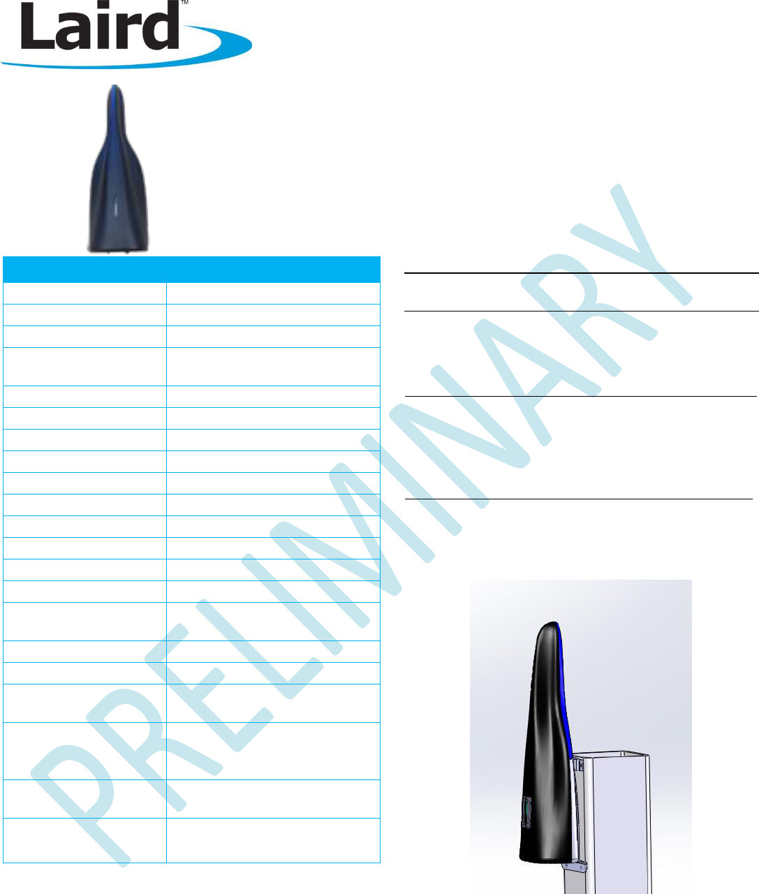
Placement
For best results, orientate RAMP Bridge vertically as shown
below. The top portion of the unit contains an omni-directional
antenna; for best results, the upper portion should be located in
free space with no obstructions in the antennas near-field.
RAMP Bridge
Installation and Operations Guide
Embedded Wireless Solutions Support Center: http://ews-
support.lairdtech.com
www.lairdtech.com/wireless
2
Laird Technologies
Americas: +1-800-492-2320
Europe: +44-1628-858-940
Hong Kong: +852-2268-6567 x026
Device Setup and Connections
The RAMP Bridge may be powered by either a network switch that supplies 48VDC (802.3af compliant) Power Over Ethernet
(POE) or by using any 802.3af compliant POE injector. If using the network switch with POE, use a standard CAT 5 or CAT 6
cable to connect the device to the switch. If using an external POE injector, set up according to the manufacturer’s
recommended connections. A few seconds after power is first applied to the Ramp Bridge device, the LEDs light up in a
pattern from top to bottom. Once finished, the device is ready to be used or configured.
Configuration
RAMP Bridge units are configured via any standard web browser. Enter the IP address of the RAMP Bridge unit into a browser
(default IP is 192.168.3.1) and log in. The default login is
root
and the default password is
summit
. We highly recommend
that you immediately change the admin credentials. To do this, click Change Admin Credentials in the upper right side of the
screen.
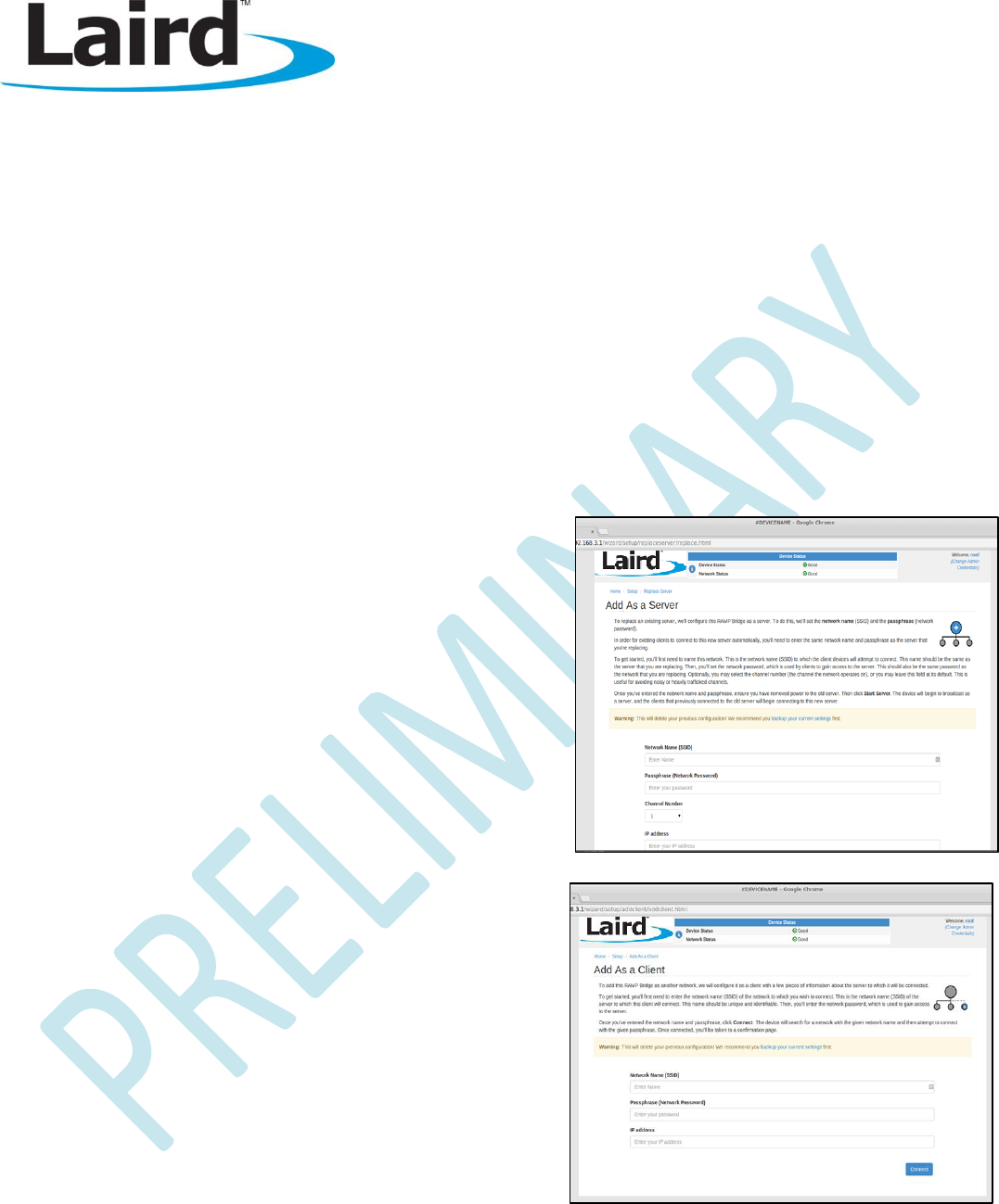
RAMP Bridge units are configured as either a server or a client. Each network should have only one server and can have
between one and five clients. By default, units are configured as a client. To set up a network, first configure the server using
the web browser as shown below.
For the server, the only configuration options:
Network Name – Unique name of the network shared among
the server and client.
Passphrase – Security key for clients to authenticate
communication to server. This is used for over the air
communication; it is not the same key as the device login
password. The server and client(s) must have the same
passphrase.
Channel Number – The channel for radio communication.
IP Address – The IP address used to connect to the device for
configuration.
Then configure each client in the network as shown in the image to
the right.
For the client, the following are the only configuration options:
Network Name – Unique name of the network shared among
the server and client.
Passphrase – Security key for clients to authenticate
communication to server. This is used for over the air
communication; it is not the same key as the device’s login
password. The server and client(s) must have the same
passphrase.
IP Address – The IP address used to connect to the device for
configuration.
Once all configurations are saved, the units can be used in a point-to-point or point-to-multipoint bridging operation.
RAMP Bridge
Installation and Operations Guide
Embedded Wireless Solutions Support Center: http://ews-
support.lairdtech.com
www.lairdtech.com/wireless
3
Laird Technologies
Americas: +1-800-492-2320
Europe: +44-1628-858-940
Hong Kong: +852-2268-6567 x026
FCC Statements of Conformity
FCC Interference Statement
This equipment has been tested and found to comply with the limits for a Class B digital device,
pursuant to Part 15 of the FCC Rules. These limits are designed to provide reasonable protection
against harmful interference in a residential installation. This equipment generates, uses, and can
radiate radio frequency energy and, if not installed and used in accordance with the instructions, may
cause harmful interference to radio communications. However, there is no guarantee that interference
will not occur in a particular installation. If this equipment does cause harmful interference to radio or
television reception, which can be determined by turning the equipment off and on, the user is
encouraged to try to correct the interference by one of the following measures:
Reorient or relocate the receiving antenna.
Increase the separation between the equipment and receiver.
Connect the equipment into an outlet on a circuit different from that to which the receiver is connected.
Consult the dealer or an experienced radio/TV technician for help.
FCC Caution: Any changes or modifications not expressly approved by the party responsible for compliance could void the
user's authority to operate this equipment.
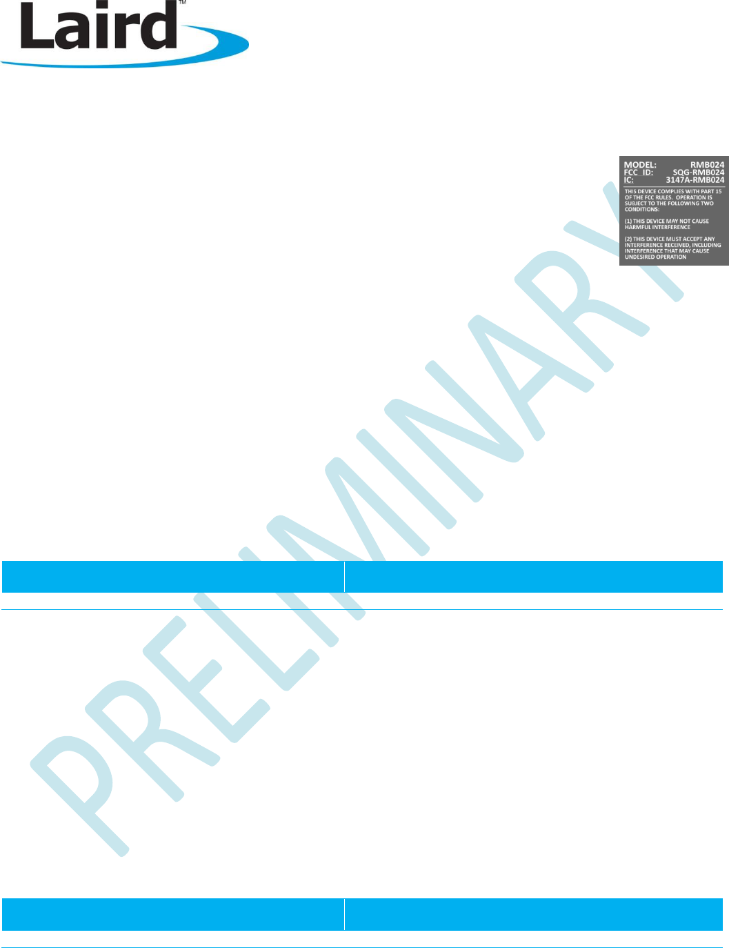
This device complies with Part 15 of the FCC Rules. Operation is subject to the following two conditions: (1) This device may
not cause harmful interference, and (2) this device must accept any interference received, including interference that may
cause undesired operation.
IMPORTANT NOTE: Radiation Exposure Statement
This equipment complies with FCC radiation exposure limits set forth for an uncontrolled environment.
The table below indicates the recommended minimum distances of operation from the human body as shown from the MPE
(Maximum Permissible Exposure) calculation:
Minimum Distance
General Public/Uncontrolled Exposure
Minimum Distance
Occupational/Controlled Exposure
50 cm (20 inches)
22 cm (9 inches)
This transmitter must not be co-located or operating in conjunction with any other antenna or transmitter.
Industry Canada Statements of Conformity
This device complies with RSS-210 of the Industry Canada Rules. Operation is subject to the following two conditions: (1) This
device may not cause harmful interference, and (2) this device must accept any interference received, including interference
that may cause undesired operation.
Ce dispositif est conforme à la norme CNR-210 d'Industrie Canada applicable aux appareils radio exempts de licence. Son fonctionnement
est sujet aux deux conditions suivantes: (1) le dispositif ne doit pas produire de brouillage préjudiciable, et (2) ce dispositif doit accepter tout
brouillage reçu, y compris un brouillage susceptible de provoquer un fonctionnement indésirable.
IMPORTANT NOTE: Radiation Exposure Statement
This equipment complies with FCC radiation exposure limits set forth for an uncontrolled environment.
The table below indicates the recommended minimum distances of operation from the human body as shown from the MPE
(Maximum Permissible Exposure) calculation:
Minimum Distance
General Public/Uncontrolled Exposure
Minimum Distance
Occupational/Controlled Exposure
50 cm (20 inches)
22 cm (9 inches)