Laird Connectivity WB45NBT 45 Series WB module with Bluetooth User Manual MSD40NBT Hardware Integration Guide v 02
Laird Technologies 45 Series WB module with Bluetooth MSD40NBT Hardware Integration Guide v 02
Contents
- 1. Users Manual
- 2. User manual
User manual

Hardware Integration Guide
Laird WB45NBT
Version 0.6
Americas: +1-800-492-2320 Option 3
Europe: +44-1628-858-940
Hong Kong: +852-2268-6567 x026

Laird WB45NBT
Hardware Integration Guide
Americas: +1-800-492-2320 Option 3
Europe: +44-1628-858-940
Hong Kong: +852-2268-6567 x026
www.lairdtech.com/wireless
2 LAIRD WB45NBT_HIG_V0_6
www.lairdtech.com/wireless
REVISION HISTORY
Version
Revision Date
Change Description
Approval
0.1 10/29/12 Preliminary Version
0.2 11/19/12 Corrected module thickness to 3.8 mm.
Added the CAN bus to the Pin Definitions and Specs table.
Added product images.
New mechanical drawing.
0.3 03/25/12 Removed documentation of 802.11n HT40 support.
Added Current Consumption numbers (Standby numbers
remain TBDs)
Updated Rx Sensitivity numbers.
Changed Summit/SDC references to
Laird
0.4
05/08/2013
Added Antenna Connector diagram.
Updated mechanical drawing.
Removed references to HT40 data rate support.
0.5
7/5/2013
Updated BT maximum transmit power.
0.6
09 August 2013
Updated regulatory information including certified antennas,
FCC, IC, and CE documentation requirements.
Updated mechanical drawings
0.7
9/18/2015
Updated regulatory information including certified antennas,
FCC, and IC

Laird WB45NBT
Hardware Integration Guide
Americas: +1-800-492-2320 Option 3
Europe: +44-1628-858-940
Hong Kong: +852-2268-6567 x026
www.lairdtech.com/wireless
3 LAIRD WB45NBT_HIG_V0_6
CONTENTS
Revision History ......................................................................................................................... 2
Contents .................................................................................................................................... 3
Scope ........................................................................................................................................ 4
Operational Description .............................................................................................................. 4
Block Diagram............................................................................................................................ 6
Specifications ............................................................................................................................. 6
Absolute Maximum Ratings ............................................................................................... 15
Recommended Operating Conditions and DC power Electrical Characteristics ................. 15
Power on Sequence ..............................................................................................................16
DC Electrical Characteristics (3.3 V signal level) ............................................................... 17
DC Electrical Characteristics (1.8 V signal level) ............................................................... 18
Pin Definitions ...........................................................................................................................20
Mechanical Specification ...........................................................................................................25
Regulatory ................................................................................................................................26
Laird WB45NBT
Hardware Integration Guide
Americas: +1-800-492-2320 Option 3
Europe: +44-1628-858-940
Hong Kong: +852-2268-6567 x026
www.lairdtech.com/wireless
4 LAIRD WB45NBT_HIG_V0_6
SCOPE
This document describes key hardware aspects of the Laird WB45NBT wireless bridge module. This
document is intended to assist device manufacturers and related parties with the integration of this
module into their host devices. Data in this document are drawn from a number of sources including data
sheets for the QUALCOMM Atheros AR6003, CSR CSR8510, and Atmel AT91SAM9G25.
Because the LAIRD WB45NBT is currently in development stage, this document is preliminary and the
information in this document is subject to change. Please contact Summit or visit the Summit website at
www.summitdata.com to obtain the most recent version of this document.
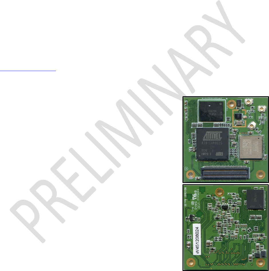
OPERATIONAL DESCRIPTION
This device is a LAIRD WB45NBT wireless bridge module, a wireless
communications subsystem that may be integrated into a variety of
host devices via a number of available electronic and logical
interfaces. The LAIRD WB45NBT provides complete enterprise-class
Wi-Fi connectivity with an integrated TCP/IP stack, full support for
IEEE 802.11a/b/g/n and Bluetooth 4.0 dual-mode air standards with a
fully integrated security supplicant providing 802.11i/WPA2 Enterprise
authentication, data encryption, and BT protocol stacks.
The WB45NBT has a wide variety of interfaces including Fast
Ethernet, serial UART, Hi-Speed USB, SPI, and I2C. The wireless
bridge may be configured, monitored, and managed via a Command
Line Interface (CLI) over an available dedicated console port, via a
web interface over a wireless or Ethernet interface, or via a remote
SDK interface over wireless or Ethernet.
The WB45NBT incorporates a Wi-Fi SiP module using Qualcomm
Atheros AR6003 which supports IEEE 802.11a/b/g/n. The CSR
(CSR8510) Bluetooth chip supports Bluetooth standard 4.0 which
includes the Bluetooth Low Energy (BLE) and legacy modes. The
product features an ARM9 processor running at 400 MHz, 64 MB of
Lower Power DDR (LPDDR) memory, and 128 MB of NAND flash
storage running at 1.8 V to minimize power consumption. Several
GPIO lines are available for data acquisition and similar applications. The platform runs an embedded
Linux operating system based on the 3.x kernel. A Software Developer’s Kit (SDK) with Application

Laird WB45NBT
Hardware Integration Guide
Americas: +1-800-492-2320 Option 3
Europe: +44-1628-858-940
Hong Kong: +852-2268-6567 x026
www.lairdtech.com/wireless
5 LAIRD WB45NBT_HIG_V0_6
Programming Interfaces (API) and software tools are available for the development of custom software
applications on the device.
The WB45NBT measures 40 mm long by 40 mm wide by 3.8 mm thick. The wireless bridge physically
interfaces to the host device via an 80 pin board to board (B2B) connector (Molex SlimStack™ 54722
Series 80 Pin Connector P/N 54722-0804), which mates to a 1.5 mm stacking height mating part from
Molex 55560 Series P/N 55560-0804. The WB45NBT may be secured to the host device via available
grounded mounting holes. The WB45NBT operates at temperatures between -20° and + 70° degrees
Celsius.
Contingent on compliance results, WB45NBT is a fully integrated module. It has its own RF shielding and
does not require shielding provided by the host device into which it is installed in order to maintain
compliance with applicable regulatory standards. As such, the device may be tested in a standalone
configuration via a breakout board (SDC-BB45NBT).
The WB45NBT provides three U.FL type antenna connectors; the Main antenna (for Wi-Fi) and the
Auxiliary (for Bluetooth) work separately to get the best coexistence performance. A third antenna
connector multiplexes both the Wi-Fi and the Bluetooth signals into a single RF port through the use of a
T/R switch however, this mode of operation is currently not supported. Supported host device antenna
types include dipole and monopole antennas.
Regulatory operational requirements are included in this document and may be incorporated into the
operating manual of any device into which the WB45NBT is installed. The WB45NBT is designed for
installation into mobile devices which typically operate at distances greater than 20 cm from the human
body and portable devices which typically operate at distances less than 20 cm from the human body.
See “Documentation Requirements” for more information.
Laird WB45NBT
Hardware Integration Guide
Americas: +1-800-492-2320 Option 3
Europe: +44-1628-858-940
Hong Kong: +852-2268-6567 x026
www.lairdtech.com/wireless
6 LAIRD WB45NBT_HIG_V0_6
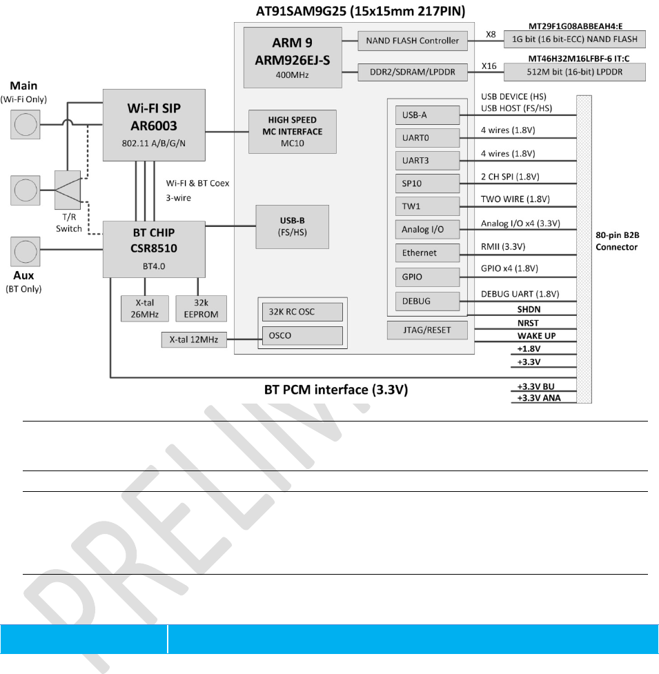
BLOCK DIAGRAM
Note:
Transmitter frequencies for Wi-Fi are 2412-2462 MHz and 5180-5805 MHz. Transmitter
frequencies for Bluetooth are 2402-2480 MHz.
Note:
Bluetooth functions on the AUX port and Wi-Fi operates at the Main antenna only.
The WB45NBT does not currently support Wi-Fi and BT sharing a single antenna
implementation.
SPECIFICATIONS
Feature
Description

Laird WB45NBT
Hardware Integration Guide
Americas: +1-800-492-2320 Option 3
Europe: +44-1628-858-940
Hong Kong: +852-2268-6567 x026
www.lairdtech.com/wireless
7 LAIRD WB45NBT_HIG_V0_6
Physical Interface
Pitch: 0.5 mm
Stacking height: 1.50 mm
Molex 54722 Series 80 Pin Connector P/N 54722-0804
Mating part:
Molex 55560 Series 80 Pin Connector P/N 55560-0804
Note:
See Mounting for mating connector options.
Ethernet Interface
(3.3 V signal level)
10/100 Mbps RMII (Reduced Media Independent Interface)
Asynchronous Serial
Port
Interfaces
(1.8 V signal level)
Four-wire UART with hardware handshaking (up to 921,600 baud)
Two-wire UART (console) for debug purpose
SPI Interface
(1.8 V signal level)
Five Wire, Master and Slave modes supported with 2 chip select
USB Interfaces
Configurable USB Host port/Device port to support USB full speed and high
speed data rates
Two Wire Interface
(1.8V signal level)
Two-wire I2C (Inter-IC)
CAN Interface
(1.8V signal level)
Controller area network (multiplexed with Two-wire UART)
Debug Interface
Two-wire UART (console) for debug purpose
Digital GPIO
(1.8 V signal level)
4 digital General Purpose I/O (GPIO)
Analog GPIO
(3.3 V signal level)
4 analog General Purpose I/O (GPIO)
PCM interface
13-bit or 16-bit linear, 8-bit μ-law or A-law companded sample formats
Antenna Interface
2 Hirose U.FL connectors for Wi-Fi (Main) and BT (Aux) separately, 50 ohm
Note:
Wi-Fi and BT sharing a single antenna is
NOT
currently supported.

Laird WB45NBT
Hardware Integration Guide
Americas: +1-800-492-2320 Option 3
Europe: +44-1628-858-940
Hong Kong: +852-2268-6567 x026
www.lairdtech.com/wireless
8 LAIRD WB45NBT_HIG_V0_6
Wi-Fi Interface
Qualcomm Atheros AR6003 1X1 802.11 a/b/g/n on 20 MHz bandwidth
Bluetooth Interface
CSR CSR8510 Bluetooth 4.0 dual-mode (EDR+BLE)
Processor Chip Set
Atmel 400 MHz ARM 9, P/N AT91SAM9G25-CU
Operating System
Embedded Linux, 3.x kernel
Memory
64 MB LPDDR
Storage
128 MB SLC NAND flash
Input Voltage
Requirements
3.3 VDC +/-5% (Backup) 3.3 VDC ±5% (system) 1.8 VDC +/-5% (Memory
and I/O interface)
Note:
Voltage ripple must be less than 30 mV.
Current Consumption
Note:
These current
consumption
measurements
were taken using
Linux kernel
version 2.6.38.
Note:
Standby refers to
the radio
operating in PM1
power saving
mode.
Mode
1.8 V
3.3 V
Avg.
Current
Max.
Current
Avg.
Current
Max.
Current
802.11a
Transmit 80 120 297 484
Receive 97 - 47 -
Standby TBD TBD TBD TBD
802.11b
Transmit 75 108 243 368
Receive 97 - 47 -
Standby TBD TBD TBD TBD
802.11g
Transmit 80 115 210 361
Receive 97 - 47 -
Standby TBD TBD TBD TBD
802.11n
(2.4 GHz)
Transmit 81 120 194 342
Receive 97 - 47 -
Standby TBD TBD TBD TBD
802.11n
(5 GHz)
Transmit TBD 120 293 448
Receive 97 - 47 -
Standby TBD TBD TBD TBD
Sleep
N/A TBD TBD TBD TBD

Laird WB45NBT
Hardware Integration Guide
Americas: +1-800-492-2320 Option 3
Europe: +44-1628-858-940
Hong Kong: +852-2268-6567 x026
www.lairdtech.com/wireless
9 LAIRD WB45NBT_HIG_V0_6
Operating Temperature
-20° to +70°C (-4°F to 158°F)
Operating Humidity
10 to 90% (non-condensing)
Storage Temperature
-30° to 85°C (-22° to 185°F)
Storage Humidity
10 to 90% (non-condensing)
Maximum Electrostatic
Discharge
Maximum Contact Discharge (CD): 4 kV
Maximum Air Discharge (AD): 8 kV
Length/Width/Thickness
40 mm (1.57 in.) x 40 mm (1.57 in.) x 3.8 mm (0.15 in.)
Note:
Length, width, and thickness measurements include the metal
shielding.
Weight
6.8 g (0.24 oz.)
Mounting
Connector and through holes.
Refer to “Mechanical Specifications” for additional information.
Recommended:
Connector:
Molex SlimStack™ P/N 55560-0807
(pitch: 0.50 mm; stack height: 1.500 mm)
Mating part: Molex 55560 Series 80 Pin Connector P/N 55560-0804
Stand-off:
EMI STOP F40M20-151126D4BM http://www.emistop.com
Wi-Fi Media
Direct Sequence-Spread Spectrum (DSSS)
Complementary Code Keying (CCK)
Orthogonal Frequency Divisional Multiplexing (OFDM)
Wi-Fi Media Access
Protocol
Carrier sense multiple access with collision avoidance (CSMA/CA)
Network Architecture
Infrastructure and ad hoc
Wi-Fi Standards
IEEE 802.11a, 802.11b, 802.11d, 802.11e, 802.11g, 802.11h, 802.11i,
802.11n

Laird WB45NBT
Hardware Integration Guide
Americas: +1-800-492-2320 Option 3
Europe: +44-1628-858-940
Hong Kong: +852-2268-6567 x026
www.lairdtech.com/wireless
10 LAIRD WB45NBT_HIG_V0_6
Wi-Fi Data Rates
Supported
802.11a
(OFDM): 6, 9, 12, 18, 24, 36, 48, 54 Mbps
802.11b
(DSSS, CCK): 1, 2, 5.5, 11 Mbps
802.11g
(OFDM): 6, 9, 12, 18, 24, 36, 48, 54 Mbps
802.11n
(OFDM,HT20,MCS 0-7): 6.5,13,19.5, 26, 39,52, 58.5, 72.2 Mbps
7.2,14.4, 21.7, 28.9,43.3, 57.8, 65 Mbps
Modulation
BPSK @ 1, 6, 6.5, 7.2 and 9 Mbps
QPSK @ 2, 12, 13, 14.4,18, 19.5 and 21.7 Mbps
CCK @ 5.5 and 11 Mbps
16-QAM @ 24, 26, 28.9, 36, 39 and 43.3 Mbps
64-QAM @ 48, 52, 54, 57.8, 58.5, 65, and 72.2 Mbps
802.11n Spatial Streams
1X1 SISO (Single Input, Single Output)
Regulatory Domain
Support
FCC (Americas, Parts of Asia, and Middle East)
ETSI (Europe, Middle East, Africa, and Parts of Asia)
MIC (Japan) (formerly TELEC)
KC (Korea) (formerly KCC)
2.4 GHz Frequency
Bands
ETSI:
2.4 GHz to 2.483 GHz
FCC:
2.4 GHz to 2.483 GHz
MIC:
2.4 GHz to 2.495 GHz
KC:
2.4 GHz to 2.483 GHz
2.4 GHz Operating
Channels
ETSI:
13 (3 non-overlapping)
FCC:
11 (3 non-overlapping)
MIC:
14 (4 non-overlapping)
KC:
13 (3 non-overlapping)
5 GHz Frequency Bands
ETSI:
5.15 GHz to 5.35 GHz
5.47 GHz to 5.725 GHz
FCC:
5.15 GHz to 5.35 GHz
5.725 GHz to 5.825 GHz
MIC:
5.15 GHz to 5.35 GHz
5.47 GHz to 5.725 GHz (W56)
KC:
5.15 GHz to 5.25 GHz
5.725 GHz to 5.825 GHz
5 GHz Operating
Channels
ETSI:
19 non-overlapping
FCC:
23 non-overlapping
MIC:
4 non-overlapping
KC:
8 non-overlapping

Laird WB45NBT
Hardware Integration Guide
Americas: +1-800-492-2320 Option 3
Europe: +44-1628-858-940
Hong Kong: +852-2268-6567 x026
www.lairdtech.com/wireless
11 LAIRD WB45NBT_HIG_V0_6
Maximum Transmit
Power
Note:
Maximum
transmits power
varies according
to individual
country
regulations. All
values nominal,
+/-2 dBm.
Note:
Summit 45 series
radios support a
single spatial
stream and 20
MHz channel
bandwidth at
2.4GHz.
802.11a
6 Mbps 15 dBm ( 31.623 mW)
54 Mbps 13 dBm ( 19.953 mW)
802.11b
1 Mbps 16 dBm ( 39.81 mW)
11 Mbps 16 dBm ( 39.81mW)
802.11g
6 Mbps 16 dBm ( 39.81 mW)
54 Mbps 14 dBm ( 25.12 mW)
802.11n (2.4 GHz)
6.5 Mbps (MCS0) 16 dBm (39.81 mW)
65 Mbps (MCS7) 12 dBm (15.85 mW)
802.11n (5 GHz HT20)
6.5 Mbps (MCS0) 15 dBm ( 31.62mW)
65 Mbps (MCS7) 12 dBm ( 15.85mW)
Bluetooth
6 dBm (3.98mW) (Class 1)

Laird WB45NBT
Hardware Integration Guide
Americas: +1-800-492-2320 Option 3
Europe: +44-1628-858-940
Hong Kong: +852-2268-6567 x026
www.lairdtech.com/wireless
12 LAIRD WB45NBT_HIG_V0_6
Typical Receiver
Sensitivity
Note:
All values
nominal, +/-3
dBm.
802.11a:
6 Mbps -93 dBm
54 Mbps -77 dBm (PER <= 10%)
802.11b:
1 Mbps -93 dBm
11 Mbps -84 dBm (PER <= 8%)
802.11g:
6 Mbps -90 dBm
54 Mbps -73 dBm (PER <= 10%)
802.11n (2.4 GHz)
MCS0 Mbps -89 dBm
MCS7 Mbps -71 dBm
802.11n (5 GHz HT20)
MCS0 Mbps
MCS7 Mbps
-93 dBm
-77 dBm
Bluetooth:
1 Mbps -89 dBm
2 Mbps -91 dBm
3 Mbps -85 dBm

Laird WB45NBT
Hardware Integration Guide
Americas: +1-800-492-2320 Option 3
Europe: +44-1628-858-940
Hong Kong: +852-2268-6567 x026
www.lairdtech.com/wireless
13 LAIRD WB45NBT_HIG_V0_6
Security
Standards
Wireless Equivalent Privacy (WEP)
Wi-Fi Protected Access (WPA)
IEEE 802.11i (WPA2)
Encryption
Wireless Equivalent Privacy (WEP, RC4 Algorithm)
Temporal Key Integrity Protocol (TKIP, RC4 Algorithm)
Advanced Encryption Standard (AES, Rijndael Algorithm)
Encryption Key Provisioning
Static (40-bit and 128-bit lengths)
Pre-Shared (PSK)
Dynamic
802.1X Extensible Authentication Protocol Types
EAP-FAST
EAP-TLS
EAP-TTLS
PEAP-GTC
PEAP-MSCHAPv2
PEAP-TLS
LEAP

Laird WB45NBT
Hardware Integration Guide
Americas: +1-800-492-2320 Option 3
Europe: +44-1628-858-940
Hong Kong: +852-2268-6567 x026
www.lairdtech.com/wireless
14 LAIRD WB45NBT_HIG_V0_6
Compliance
Note:
These regulatory
domain
certifications are
pending.
ETSI Regulatory Domain
EN 300 328
EN 300 328 v1.7.1 (BT 2.1)
EN 301 489-1
EN 301 489-17
EN 301 893
EN 60950-1
EN 55022:2006 Class B
EN 55024:1998 +A1:2001, A2:2003
EN 61000-3-2:2006
EN 61000-3-3:1995 +A1:2001, A2:2005
EU 2002/95/EC (RoHS)
FCC Regulatory Domain
FCC 15.247 DTS – 802.11b/g (Wi-Fi): 2.4 GHz & 5.8 GHz
FCC 15.407 UNII – 802.11a (Wi-Fi): 2.4 GHz & 5.4 GHz
FCC 15.247 DSS – BT 2.1
FCC Part 15 Class B
UL 60950
Industry Canada
RSS-210 – 802.11a/b/g/n (Wi-Fi) – 2.4 GHz, 5.8 GHz, 5.2 GHz, and 5.4
GHz
ICES-003, Class B
CSA C22.2, No. 60950
RSS-210 – BT 2.1
MIC (Japan) Regulatory Domain (formerly TELEC)
Article 2 Item 19, Category WW (2.4GHz Channels 1-13)
Article 2 Item 19-2, Category GZ (2.4GHz Channel 14)
Article 2 Item 19-3 Category XW (5150-5250 W52 & 5250-5350 W53)
VCCI Class B
Article 2-1 Item 19-2 (BT 2.1)
Certifications
Note:
These
certifications are
pending.
Wi-Fi Alliance
802.11a, 802.11b, 802.11g , 802.11n
WPA Enterprise
WPA2 Enterprise
Cisco Compatible Extensions (Version 4)

Laird WB45NBT
Hardware Integration Guide
Americas: +1-800-492-2320 Option 3
Europe: +44-1628-858-940
Hong Kong: +852-2268-6567 x026
www.lairdtech.com/wireless
15 LAIRD WB45NBT_HIG_V0_6
Warranty
Limited Lifetime
All specifications are subject to change without notice
Absolute Maximum Ratings
Parameter
Comments
Conditions
Min.
Typ.
Max.
Unit
Input Voltage
3.3V VCC pin
With respect to ground
-0.3 - 3.8 V
1.8V VCC pin -0.3 - 2.0 V
Any 3.3V IO pin -0.3 - 3.8 V
Any 1.8V IO pin -0.3 2.0 V
RF input
Maximum RF input from
the antenna port
(reference to 50 ohm)
+10 dBm
Note:
Voltage operated over the maximum limit may cause permanent damage to the device.
These are stress ratings only; functional operation of the device at these or any other
conditions beyond those indicated under Recommended Operating Conditions is not implied.
Exposure to absolute-maximum-rated conditions for extended periods may affect device
reliability.
Recommended Operating Conditions and DC power Electrical Characteristics
Parameter
Comments
Conditions
Min.
Typ.
Max.
Unit
Supply Voltage
3.3 V/3.3 V_BU/”3.3 V_ANA
1.8 V VCC
3.14
1.71
3.3
1.8
3.47
1.89
V
Voltage Ripple
3.3 V/3.3 V_BU
3.3 V_ANA/1.8 V - - 30 mV
Recommend
voltage supply
current rating
3.3 V_BU
3.3 V_ANA
3.3 V
1.8 V
-
10
100
1000
500
mA
DC Output Current
Analog IO pin
3.3 V signal
level - - 8 mA
DC Output Current
Digital IO pin
1.8 V signal
level - - 2 mA
Voltage Rise Time
At power on
3.3 V / 3.3 VBU /
1.8 V - - 5 ms
Operating Current
WLAN Continuous
-
TBD
mA
Laird WB45NBT
Hardware Integration Guide
Americas: +1-800-492-2320 Option 3
Europe: +44-1628-858-940
Hong Kong: +852-2268-6567 x026
www.lairdtech.com/wireless
16 LAIRD WB45NBT_HIG_V0_6
Parameter
Comments
Conditions
Min.
Typ.
Max.
Unit
sub-system
receive
IEEE PSM
TBD
-
-
Continuous
transmit (3.3 V/
1.8 V)
-
330/
85 400/100
Bluetooth
sub-system
Continuous
receive - TBD
mA
Continuous
transmit
CPU
sub-system
Varies with
system load - TBD mA
Operating
Temperature
-20 25 +70 °C
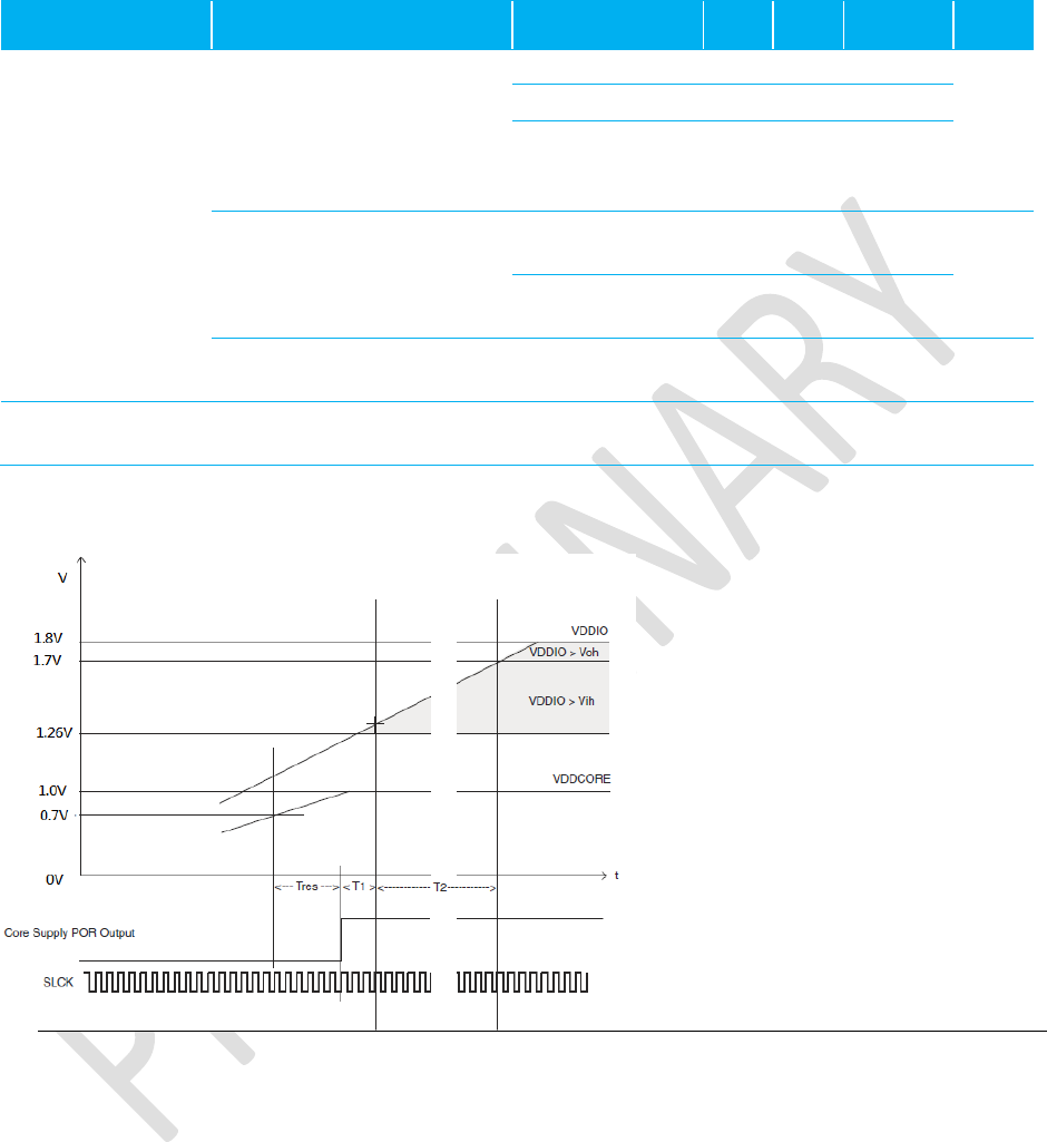
Power on Sequence
Notes:
Apply the 3.3 V (backup and system) and 1.8 V (memory & interface I/O) at the same time.
The CPU implements the internal POR (Power-On-Reset) and will guarantee the power
sources reach their target values prior to the release of POR.
Tres=30 us, T1=66 us, T2=352 us (minimum)
Establish the VDDIO/CDDIOP (1.8 V for memory & interface I/O) and VCCBU (3.3 V) first,
then VDDPLL (1.0 V from LDO), and the VDDCORE (1.0 V from DC-DC regulator) to ensure

Laird WB45NBT
Hardware Integration Guide
Americas: +1-800-492-2320 Option 3
Europe: +44-1628-858-940
Hong Kong: +852-2268-6567 x026
www.lairdtech.com/wireless
17 LAIRD WB45NBT_HIG_V0_6
reliable device operation. This is implemented on the WB45NBT, user simply apply 3.3 V
(backup and system) and 1.8 V (memory & interface I/O) at the same time.
DC Electrical Characteristics (3.3 V signal level)
I/O
Indicates whether the signal is input or output state.
PU/PD
Indicates whether Pull-Up, Pull-Down, or nothing is enabled.
ST
Indicates if Schmitt Trigger is enabled.
TR
Tri-state
Parameter
Conditions
Min.
Typ.
Max.
Unit
AIO[0-3]
IRQ
SHDN
WKUP
ETXEN;ETX[0-1];ERXER;ERX[0-1];EMDC;EMDIO;ECRSDV;EREF_CLK
I/O;PU;ST
I;PU;ST
O;PU
I;ST
Note
: PU;ST
VIL Input Low-Level Voltage -0.3 - 0.8 V
VIH Input High-Level Voltage 2.0 3.6 V
VOL Output Low-Level Voltage 0.4 V
VOH Output High-Level Voltage 2.9 V
VT- Schmitt trigger Negative-going threshold Voltage 0.8 1.1 V
VT+ Schmitt trigger Positive-going threshold Voltage 1.6 2.0 V
VHYS Schmitt trigger Hysteresis 0.5 0.75 V
RPULLUP Pull-up/Pull-down Resistance 40 75 190 KΩ
IO Output Current 8 mA

Laird WB45NBT
Hardware Integration Guide
Americas: +1-800-492-2320 Option 3
Europe: +44-1628-858-940
Hong Kong: +852-2268-6567 x026
www.lairdtech.com/wireless
18 LAIRD WB45NBT_HIG_V0_6
DC Electrical Characteristics (1.8 V signal level)
I/O
Indicates whether the signal is input or output state.
PU/PD
Indicates whether Pull-Up, Pull-Down or nothing is enabled.
ST
Indicates if Schmitt Trigger is enabled.
TR
Tri-state
Parameter
Conditions
Min.
Typ.
Max.
Unit
GPIO[0-3]
TWCK1;TWD1
WOW
WIFI_GPIO
URTS0;UCTS0;URXD0;UTXD0;URTS3;UCTS3;URXD3;UTXD3
DTXD;DRXD
PCM_CLK;PCM_SYNC;PCM_OUT;PCM_IN
I/O;PU;ST
Note
: PU;ST
O
I/O
Notes:
PU;ST
PU;ST
PD;TR
VIL Input Low-Level Voltage -0.3 - 0.54 V
VIH Input High-Level Voltage 1.26 2.1 V
VOL Output Low-Level Voltage 0.4 V
VOH Output High-Level Voltage 1.4 V
VT- Schmitt trigger Negative-going threshold Voltage 0.54 V
VT+ Schmitt trigger Positive-going threshold Voltage 0.54 V
VHYS Schmitt trigger Hysteresis 0.28 0.6 V
RPULLUP Pull-up/Pull-down
Resistance 240 1000 KΩ
IO Output Current 2 mA
Note:
We recommend that 1.8 V signal I/O pins should not be used to drive the external circuit
directly due to its weak drive capability. A buffer/driver should be used in such applications.

Laird WB45NBT
Hardware Integration Guide
Americas: +1-800-492-2320 Option 3
Europe: +44-1628-858-940
Hong Kong: +852-2268-6567 x026
www.lairdtech.com/wireless
19 LAIRD WB45NBT_HIG_V0_6

Laird WB45NBT
Hardware Integration Guide
Americas: +1-800-492-2320 Option 3
Europe: +44-1628-858-940
Hong Kong: +852-2268-6567 x026
www.lairdtech.com/wireless
20 LAIRD WB45NBT_HIG_V0_6
PIN DEFINITIONS
Table 1: Pin Definitions
#
Pin Name
Section
I/O
Reference
Description
If unused
1 +3.3V_ANA - - +3.3 V for analog I/O interface 3.3 V must be
supplied
2 +3.3V_BU - - +3.3 V for system back up 3.3 V must be
supplied
3 GND
- Ground Ground
Must be
connected to
GND
4 GND
- Ground Ground
Must be
connected to
GND
5 AIO-1
*VBUS_EN
Analog
I/O I/O
*O +3.3 V_ANA
Analog I/O
*USB interface in Host mode;
used to control (High enable)
the USB bus power (5 V).
6 WKUP
I +3.3 V_BU
Wake up the processor from
deep sleep mode.
Low active to wake up the
CPU.
Internal 100k pull-up
7 SHDN
O
+3.3 V_BU Shut down the external power
supply for the module to save
power consumption.
Low active to shut down the
power supply.
Internal 100K pull-up
8 AIO-0
*VBUS_SENS
Analog
I/O
I/O
*I +3.3 V_ANA
Analog I/O
*When USB interfaces in
Device mode; It is used to
sense the USB bus power (5
V).
Note:
A voltage divider is
needed to implement.
Please reference the
BB45NBT design.
9 AIO-3 Analog
I/O I/O +3.3 V_ANA Analog I/O
10 AIO-2 Analog I/O +3.3 V_ANA Analog I/O

Laird WB45NBT
Hardware Integration Guide
Americas: +1-800-492-2320 Option 3
Europe: +44-1628-858-940
Hong Kong: +852-2268-6567 x026
www.lairdtech.com/wireless
21 LAIRD WB45NBT_HIG_V0_6
#
Pin Name
Section
I/O
Reference
Description
If unused
*OVER_CURREN
T
I/O
*I
*When USB interfaces in Host
mode; It is used to sense the
USB bus power (5V) running
over the current limit.
Note:
A voltage switch is
needed to implement. Please
reference the BB45NBT
design.
11 IRQ Control I +3.3 V External Interrupt Input
12 GND
- Ground Ground
Must be
connected to
GND
13 GND
- Ground Ground
Must be
connected to
GND
14 EMDC Ethernet O +3.3 V Ethernet Management Data
Clock
15 ETXEN Ethernet O +3.3 V Ethernet Transmit Enable
16 GND
- Ground Ground
Must be
connected to
GND
17 ETX0 Ethernet O +3.3 V Ethernet Transmit Data 0
18 ETX1 Ethernet O +3.3 V Ethernet Transmit Data 1
19 ERXER Ethernet I +3.3 V Ethernet Receive Error
20 ERX0 Ethernet I +3.3 V Ethernet Receive Data 0
21 GND
- Ground Ground
Must be
connected to
GND
22 ERX1 Ethernet I +3.3 V Ethernet Receive Data 1
23 REF_CLK Ethernet I +3.3 V Ethernet 50MHz Clock Leave open
24 ECRSDV Ethernet I +3.3 V Ethernet Receive Data Valid
25 GND
- Ground Ground
Must be
connected to
GND
26 EMDIO Ethernet I/O +3.3 V Ethernet Management Data
Input/Output
27 TWD1 I/O +1.8 V Twist wire bus Data (I2C Data
line)

Laird WB45NBT
Hardware Integration Guide
Americas: +1-800-492-2320 Option 3
Europe: +44-1628-858-940
Hong Kong: +852-2268-6567 x026
www.lairdtech.com/wireless
22 LAIRD WB45NBT_HIG_V0_6
#
Pin Name
Section
I/O
Reference
Description
If unused
28 GND
- Ground Ground
Must be
connected to
GND
29 TWCK1 O +1.8 V Twist wire bus Clock (I2C
Clock line)
30 +1.8V
- - 1.8 V for Memory
(NAND/LPDDR), bus
interface and Wi-Fi/BT bus
configuration.
31 GND
- Ground Ground
Must be
connected to
GND
32 GND
- Ground Ground
Must be
connected to
GND
33 GPIO-0 GPIO I/O +1.8 V General I/O 0 Leave open
34 GPIO-1 GPIO I/O +1.8 V General I/O 1 Leave open
35 GPIO-2 GPIO I/O +1.8 V General I/O 2 Leave open
36 GPIO-3 GPIO I/O +1.8 V General I/O 3 Leave open
37 GND
- Ground Ground
Must be
connected to
GND
38 GND
- Ground Ground
Must be
connected to
GND
39 URXD3 UART3 I +1.8 V UART3 Receive Data Leave open
40 URTS3 UART3 O +1.8 V UART3 Ready To Send Leave open
41 UTXD3 UART3 O +1.8 V UART3 Transmit Data Leave open
42 UCTS3 UART3 I +1.8 V UART3 Clear To Send Leave open
43 GND
- Ground Ground
Must be
connected to
GND
44 GND
- Ground Ground
Must be
connected to
GND
45 URXD0 UART0 I +1.8 V UART0 Receive Data Leave open
46 URTS0 UART0 O +1.8 V UART0 Ready To Send Leave open

Laird WB45NBT
Hardware Integration Guide
Americas: +1-800-492-2320 Option 3
Europe: +44-1628-858-940
Hong Kong: +852-2268-6567 x026
www.lairdtech.com/wireless
23 LAIRD WB45NBT_HIG_V0_6
#
Pin Name
Section
I/O
Reference
Description
If unused
47 UTXD0 UART0 O +1.8 V UART0 Transmit Data Leave open
48 UCTS0 UART0 I +1.8 V UART0 Clear To Send Leave open
49 GND
- Ground Ground
Must be
connected to
GND
50 GND
- Ground Ground
Must be
connected to
GND
51 SPI0_CSn1 SPI0 O +1.8 V SPI0 Chip Select. Active Low
*Only for SPI in Master mode. Leave open
52 SPI0_MISO SPI0 I/O +1.8 V SPI0 Master In Slave Out Leave open
53 GND
- Ground Ground
Must be
connected to
GND
54 SPI0_MOSI SPI0 I/O +1.8 V SPI0 Master Out Slave In Leave in
55 SPI0_CLK SPI0 I/O +1.8 V SPI0 Serial Clock (Master:O
Slave:I) Leave open
56 SPI0_CSn0
SPI0 I/O +1.8 V SPI0 Chip Select. (Master:O
Slave:I)Active Low
Leave open
57 GND
- Ground Ground
Must be
connected to
GND
58 GND
- Ground Ground
Must be
connected to
GND
59 DRXD DBGU I +1.8 V Debug UART Receive Data
CANRX0 47K Pull-Up
60 +3.3V - - 3.3V for CPU,Wi-Fi and BT 3.3V must be
supplied
61 DTXD DBGU O +1.8V Debug UART Transmit Data
CANTX0 Leave Open
62 +3.3V - - 3.3V for CPU,Wi-Fi and BT 3.3V must be
supplied
63 GND - Ground Ground Must be
connected to

Laird WB45NBT
Hardware Integration Guide
Americas: +1-800-492-2320 Option 3
Europe: +44-1628-858-940
Hong Kong: +852-2268-6567 x026
www.lairdtech.com/wireless
24 LAIRD WB45NBT_HIG_V0_6
#
Pin Name
Section
I/O
Reference
Description
If unused
GND
64 GND
- Ground Ground
Must be
connected to
GND
65 HHSDPA USB
Device
I/O USB (Host/Device) D+
66 NRST Control I +1.8V CPU Reset; Low active. Leave open
67 HHSDMA USB
Device
I/O USB (Host/Device) D-
68 WOW O +1.8V Wake On Wireless LAN
69 GND
- Ground Ground
Must be
connected to
GND
70 Wi-Fi GPIO I/O +1.8V Reserved for Wi-Fi GPIO Leave open
71 GND
- Ground Ground
Must be
connected to
GND
72 GND
- Ground Ground
Must be
connected to
GND
73 PCM_CLK
I
O
+1.8V
+1.8V
PCM CLK input
when BT acts as Slave
PCM CLK output
when BT acts as Master
Leave open
74 PCM_IN I +1.8V PCM signal input.
75 GND
- Ground Ground
Must be
connected to
GND
76 GND
- Ground Ground
Must be
connected to
GND
77 PCM_SYNC I/O +1.8V PCM signal sync
78 PCM_OUT O +1.8V PCM signal output
79 GND
- Ground Ground
Must be
connected to
GND
80 GND - Ground Ground Must be
Laird WB45NBT
Hardware Integration Guide
Americas: +1-800-492-2320 Option 3
Europe: +44-1628-858-940
Hong Kong: +852-2268-6567 x026
www.lairdtech.com/wireless
25 LAIRD WB45NBT_HIG_V0_6
#
Pin Name
Section
I/O
Reference
Description
If unused
connected to
GND
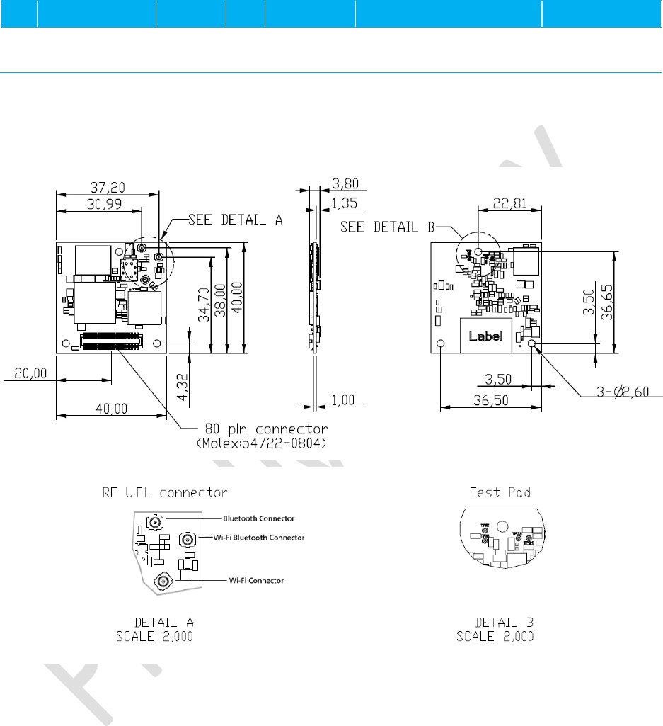
MECHANICAL SPECIFICATION
Mounting
TBD

Laird WB45NBT
Hardware Integration Guide
Americas: +1-800-492-2320 Option 3
Europe: +44-1628-858-940
Hong Kong: +852-2268-6567 x026
www.lairdtech.com/wireless
26 LAIRD WB45NBT_HIG_V0_6
REGULATORY
Certified Antennas
The WB45NBT will be tested to the regulatory standards defined in the “Certifications” section of the
Specifications table above. Summit plans to conduct these tests with the following antennas:
Model Type Connector Maximum Gain
MAG.LAYERS
EDA-1513-25GR2-B2-CY
Dipole SMA
Jack Reverse
2 dBi
MAG.LAYERS
PCA-4606-2G4C1-A13-CY
PCB Dipole TNOV 2.2 dBi
Laird
NanoBlade-IP04
PCB Dipole IPEX MHF
2.4-2.5 GHz: 2 dBi
5.15-5.35 GHz: 3.9 dBi
5.6 GHz: 4 dBi
Laird
MAF95310 Mini NanoBlade Flex
PCB Dipole IPEX MHF 2.4 GHz: 2.79 dBi
5 GHz: 3.38 dBi
Laird
NanoBlue-IP04
PCB Dipole IPEX MHF 2.5 GHz only: 2 dBi
Ethertronics
WLAN_1000146
Magnetic
Dipole IPEX MHF
2.4-2.5 GHz: 2 dBi
4.9-5.1 GHz: 3.5 dBi
5.15-5.35 GHz: 3.5 dBi
5.7-5.9 GHz: 3.5 dBi
Amphenol
MG7018-41-000-R Dipole IPEX MHF
2.4-2.5 GHz: 1.87 dBi
5.15-5.25 GHz: 0.85 dBi
5.25-5.35 GHz: 0.6 dBi
5.47-5.85 GHz: 0.92 dBi
Amphenol
MG7324-41-000-R Dipole IPEX MHF
2.4-2.5 GHz: 1.32 dBi
5.15-5.25 GHz: 1.04 dBi
5.25-5.35 GHz: 1.6 dBi
5.47-5.725 GHz: 2.75 dBi
5.725-5.85 GHz: 2.24 dBi
Documentation Requirements
In order to ensure regulatory compliance, when integrating the WB45NBT into a host device, it is
necessary to meet the documentation requirements set forth by the applicable regulatory agencies. The
following sections (FCC, Industry Canada, and European Union) outline the information that may be

Laird WB45NBT
Hardware Integration Guide
Americas: +1-800-492-2320 Option 3
Europe: +44-1628-858-940
Hong Kong: +852-2268-6567 x026
www.lairdtech.com/wireless
27 LAIRD WB45NBT_HIG_V0_6
included in the user’s guide and external labels for the host devices into which the WB45NBT is
integrated.
Federal Communication Commission Interference Statement
This equipment has been tested and found to comply with the limits for a Class B digital device,
pursuant to Part 15 of the FCC Rules. These limits are designed to provide reasonable protection
against harmful interference in a residential installation. This equipment generates, uses, and can
radiate radio frequency energy and, if not installed and used in accordance with the instructions, may
cause harmful interference to radio communications. However, there is no guarantee that interference
will not occur in a particular installation. If this equipment does cause harmful interference to radio or
television reception, which can be determined by turning the equipment off and on, the user is
encouraged to try to correct the interference by one of the following measures:
1. Reorient or relocate the receiving antenna.
2. Increase the separation between the equipment and receiver.
3. Connect the equipment into an outlet on a circuit different from that to which the receiver is
connected.
4. Consult the dealer or an experienced radio/TV technician for help.
FCC Caution:
Any changes or modifications not expressly approved by the party responsible for
compliance could void the user's authority to operate this equipment.
This device complies with Part 15 of the FCC Rules. Operation is subject to the following two
conditions: (1) This device may not cause harmful interference, and (2) this device must accept any
interference received, including interference that may cause undesired operation.
This device is restricted to
indoor
use when operated in the 5.15 to 5.25 GHz frequency range.
FCC requires this product to be used indoors for the frequency range 5.15 to 5.25 GHz to reduce the
potential for harmful interference to co-channel Mobile Satellite systems.
This device does not permit operations on channels 116-128 (5580 – 5640 MHz) for 11na and 120-
128 (5600-5640 MHz) for 11a which overlap the 5600 -5650 MHz band.
IMPORTANT NOTE: FCC Radiation Exposure Statement:
This equipment complies with FCC radiation exposure limits set forth for an uncontrolled
environment. This equipment should be installed and operated with minimum distance 20cm
between the radiator & your body.
This device is intended only for OEM integrators under the following conditions:
The antenna must be installed such that 20 cm is maintained between the antenna and users,
and

Laird WB45NBT
Hardware Integration Guide
Americas: +1-800-492-2320 Option 3
Europe: +44-1628-858-940
Hong Kong: +852-2268-6567 x026
www.lairdtech.com/wireless
28 LAIRD WB45NBT_HIG_V0_6
The transmitter module may not be co-located with any other transmitter or antenna,
For all products marketed in the United States, the OEM must limit the operation channels from
CH1 to CH11 for 2.4 GHz band by the supplied firmware programming tool. The OEM shall not
supply any tool or information to the end-user regarding Regulatory Domain change.
As long as the three conditions above are met, further transmitter testing is not required. However,
the OEM integrator is still responsible for testing their end-product for any additional compliance
requirements required with this module installed.

Laird WB45NBT
Hardware Integration Guide
Americas: +1-800-492-2320 Option 3
Europe: +44-1628-858-940
Hong Kong: +852-2268-6567 x026
www.lairdtech.com/wireless
29 LAIRD WB45NBT_HIG_V0_6
IMPORTANT NOTE: In the event that these conditions cannot be met (for example, certain laptop
configurations or co-location with another transmitter), then the FCC
authorization is no longer considered valid and the FCC ID cannot be used on
the final product. In these circumstances, the OEM integrator is responsible for
re-evaluating the end product (including the transmitter) and obtaining a
separate FCC authorization.
End Product Labeling
This transmitter module is authorized only for use in device where the antenna is installed such that 20
cm is maintained between the antenna and users. The final end product must be labeled in a visible area
with the following: “Contains FCC ID: SQG-WB45NBT”.
Manual Information to the End User
The OEM integrator
may NOT
provide information to the end user regarding how to install or remove this
RF module in the user’s manual of the end product which integrates this module.
The end user manual shall include all required regulatory information/warnings as show in this Hardware
Integration Guide.
User’s Guide Requirements (for Model # WB45NBT)
RF Radiation Hazard Warning
To ensure compliance with FCC and Industry Canada RF exposure requirements, this device must be
installed in a location where the antennas of the device will have a minimum distance of at least 20 cm
from all persons. Using higher gain antennas and types of antennas not certified for use with this product
is not allowed. The device shall not be co-located with another transmitter.
Installez l'appareil en veillant à conserver une distance d'au moins 20 cm entre les éléments rayonnants
et les personnes. Cet avertissement de sécurité est conforme aux limites d'exposition définies par la
norme CNR-102 at relative aux fréquences radio.
Maximum Antenna Gain – If the integrator configures the device such that the antenna is detectable from
the host product.
"This device complies with Industry Canada licence-exempt RSS standard(s). Operation is subject to the
following two conditions: (1) this device may not cause interference, and (2) this device must accept any
interference, including interference that may cause undesired operation of the device.
Le présent appareil est conforme aux CNR d'Industrie Canada applicables aux appareils radio exempts
de licence. L'exploitation est autorisée aux deux conditions suivantes : (1) l'appareil ne doit pas produire
de brouillage, et (2) l'utilisateur de l'appareil doit accepter tout brouillage radioélectrique subi, même si le
brouillage est susceptible d'en compromettre le fonctionnement.

Laird WB45NBT
Hardware Integration Guide
Americas: +1-800-492-2320 Option 3
Europe: +44-1628-858-940
Hong Kong: +852-2268-6567 x026
www.lairdtech.com/wireless
30 LAIRD WB45NBT_HIG_V0_6
This radio transmitter (identify the device by certification number, or model number if Category II) has
been approved by Industry Canada to operate with the antenna types listed below with the maximum
permissible gain and required antenna impedance for each antenna type indicated. Antenna types not
included in this list, having a gain greater than the maximum gain indicated for that type, are strictly
prohibited for use with this device.
Le présent émetteur radio (IC: 3147A-WB45NBT) a été approuvé par Industrie Canada pour fonctionner
avec les types d'antenne énumérés ci-dessous et ayant un gain admissible maximal et l'impédance
requise pour chaque type d'antenne. Les types d'antenne non inclus dans cette liste, ou dont le gain est
supérieur au gain maximal indiqué, sont strictement interdits pour l'exploitation de l'émetteur.
please refer to page 22 for antenna list
This device is intended only for OEM integrators under the following conditions:
1) The antenna must be installed such that 20 cm is maintained between the antenna and users, and
2) The transmitter module may not be co-located with any other transmitter or antenna.
As long as 2 conditions above are met, further transmitter test will not be required. However, the OEM
integrator is still responsible for testing their end-product for any additional compliance requirements
required with this module installed.
Cet appareil est conçu uniquement pour les intégrateurs OEM dans les conditions suivantes:
1) L'antenne doit être installée de telle sorte qu'une distance de 20 cm est respectée entre l'antenne et
les utilisateurs, et
2) Le module émetteur peut ne pas être coïmplanté avec un autre émetteur ou antenne.
Tant que les 2 conditions ci-dessus sont remplies, des essais supplémentaires sur l'émetteur ne seront
pas nécessaires. Toutefois, l'intégrateur OEM est toujours responsable des essais sur son produit final
pour toutes exigences de conformité supplémentaires requis pour ce module installé.
IMPORTANT NOTE:
In the event that these conditions can not be met (for example certain laptop configurations or co-location
with another transmitter), then the Canada authorization is no longer considered valid and the IC ID can
not be used on the final product. In these circumstances, the OEM integrator will be responsible for re-
evaluating the end product (including the transmitter) and obtaining a separate Canada authorization.
NOTE IMPORTANTE:
Dans le cas où ces conditions ne peuvent être satisfaites (par exemple pour certaines configurations
d'ordinateur portable ou de certaines co-localisation avec un autre émetteur), l'autorisation du Canada
n'est plus considéré comme valide et l'ID IC ne peut pas être utilisé sur le produit final. Dans ces

Laird WB45NBT
Hardware Integration Guide
Americas: +1-800-492-2320 Option 3
Europe: +44-1628-858-940
Hong Kong: +852-2268-6567 x026
www.lairdtech.com/wireless
31 LAIRD WB45NBT_HIG_V0_6
circonstances, l'intégrateur OEM sera chargé de réévaluer le produit final (y compris l'émetteur) et
l'obtention d'une autorisation distincte au Canada.
End Product Labeling
This transmitter module is authorized only for use in device where the antenna may be installed such that
20 cm may be maintained between the antenna and users. The final end product must be labeled in a
visible area with the following: “Contains IC:3147A-WB45NBT”.
Plaque signalétique du produit final
Ce module émetteur est autorisé uniquement pour une utilisation dans un dispositif où l'antenne peut être
installée de telle sorte qu'une distance de 20cm peut être maintenue entre l'antenne et les utilisateurs. Le
produit final doit être étiqueté dans un endroit visible avec l'inscription suivante: "Contient des IC: 3147A-
WB45NBT".
Manual Information To the End User
The OEM integrator has to be aware not to provide information to the end user regarding how to install or
remove this RF module in the user’s manual of the end product which integrates this module.
The end user manual shall include all required regulatory information/warning as show in this manual.
Manuel d'information à l'utilisateur final
L'intégrateur OEM doit être conscient de ne pas fournir des informations à l'utilisateur final quant à la
façon d'installer ou de supprimer ce module RF dans le manuel de l'utilisateur du produit final qui intègre
ce module.
Le manuel de l'utilisateur final doit inclure toutes les informations réglementaires requises et
avertissements comme indiqué dans ce manuel.
European Union
User’s Guide Requirements
The integrator must include specific information in the user’s guide for the device into which the
WB45NBT is integrated. In addition to the required FCC and IC statements outlined above, the following
R&TTE statements must be added in their entirety and without modification into a prominent place in the
user’s guide for the device into which the WB45NBT is integrated:
This device complies with the essential requirements of the R&TTE Directive 1999/5/EC. The
following test methods have been applied in order to prove presumption of conformity with the
essential requirements of the R&TTE Directive 1999/5/EC:
EN60950-1:2001 A11:2004
Safety of Information Technology Equipment
EN 300 328 V1.7.1: (2006-10)

Laird WB45NBT
Hardware Integration Guide
Americas: +1-800-492-2320 Option 3
Europe: +44-1628-858-940
Hong Kong: +852-2268-6567 x026
www.lairdtech.com/wireless
32 LAIRD WB45NBT_HIG_V0_6
Electromagnetic compatibility and Radio spectrum Matters (ERM); Wideband Transmission
systems; Data transmission equipment operating in the 2,4 GHz ISM band and using spread
spectrum modulation techniques; Harmonized EN covering essential requirements under article
3.2 of the R&TTE Directive
EN 301 489-1 V1.6.1: (2005-09)
Electromagnetic compatibility and Radio Spectrum Matters (ERM); ElectroMagnetic Compatibility
(EMC) standard for radio equipment and services; Part 1: Common technical requirements
EN 301 489-17 V1.2.1 (2002-08)
Electromagnetic compatibility and Radio spectrum Matters (ERM); ElectroMagnetic Compatibility
(EMC) standard for radio equipment and services; Part 17: Specific conditions for 2,4 GHz
wideband transmission systems and 5 GHz high performance RLAN equipment
EN 301 893 V1.5.1 (2008-12)
Electromagnetic compatibility and Radio spectrum Matters (ERM); Broadband Radio Access
Networks (BRAN); Specific conditions for 5 GHz high performance RLAN equipment
EU 2002/95/EC (RoHS)
Declaration of Compliance – EU Directive 2003/95/EC; Reduction of Hazardous Substances
(RoHS)
This device is a 2.4 GHz wideband transmission system (transceiver), intended for use in all EU
member states and EFTA countries, except in France and Italy where restrictive use applies.
In Italy the end-user should apply for a license at the national spectrum authorities in order to obtain
authorization to use the device for setting up outdoor radio links and/or for supplying public access to
telecommunications and/or network services.
This device may not be used for setting up outdoor radio links in France and in some areas the RF
output power may be limited to 10 mW EIRP in the frequency range of 2454 – 2483.5 MHz. For
detailed information the end-user should contact the national spectrum authority in France.
Č
esky [Czech]
[Jméno výrobce]
tímto prohlašuje, že tento
[typ za
ř
ízení]
je ve shodě se základními
požadavky a dalšími příslušnými ustanoveními směrnice 1999/5/ES.
Dansk [Danish]
Undertegnede
[fabrikantens navn]
erklærer herved, at følgende udstyr
[udstyrets
typebetegnelse]
overholder de væsentlige krav og øvrige relevante krav i direktiv
1999/5/EF.
Deutsch
[German]
Hiermit erklärt
[Name des Herstellers]
, dass sich das Gerät
[Gerätetyp]
in
Übereinstimmung mit den grundlegenden Anforderungen und den übrigen

Laird WB45NBT
Hardware Integration Guide
Americas: +1-800-492-2320 Option 3
Europe: +44-1628-858-940
Hong Kong: +852-2268-6567 x026
www.lairdtech.com/wireless
33 LAIRD WB45NBT_HIG_V0_6
einschlägigen Bestimmungen der Richtlinie 1999/5/EG befindet.
Eesti [Estonian]
Käesolevaga kinnitab
[tootja nimi = name of manufacturer]
seadme
[seadme tüüp =
type of equipment]
vastavust direktiivi 1999/5/EÜ põhinõuetele ja nimetatud
direktiivist tulenevatele teistele asjakohastele sätetele.
English
Hereby,
[name of manufacturer]
, declares that this
[type of equipment]
is in
compliance with the essential requirements and other relevant provisions of Directive
1999/5/EC.
Español
[Spanish]
Por medio de la presente
[nombre del fabricante]
declara que el
[clase de equipo]
cumple con los requisitos esenciales y cualesquiera otras disposiciones aplicables o
exigibles de la Directiva 1999/5/CE.
Ελληνική
[Greek]
ΜΕ ΤΗΝ ΠΑΡΟΥΣΑ
[name of manufacturer]
ΔΗΛΩΝΕΙ ΟΤΙ
[type of equipment]
ΣΥΜΜΟΡΦΩΝΕΤΑΙ ΠΡΟΣ ΤΙΣ ΟΥΣΙΩΔΕΙΣ ΑΠΑΙΤΗΣΕΙΣ ΚΑΙ ΤΙΣ ΛΟΙΠΕΣ
ΣΧΕΤΙΚΕΣ ΔΙΑΤΑΞΕΙΣ ΤΗΣ ΟΔΗΓΙΑΣ 1999/5/ΕΚ.
Français
[French]
Par la présente
[nom du fabricant]
déclare que l'appareil
[type d'appareil]
est
conforme aux exigences essentielles et aux autres dispositions pertinentes de la
directive 1999/5/CE.
Italiano [Italian]
Con la presente
[nome del costruttore]
dichiara che questo
[tipo di apparecchio]
è
conforme ai requisiti essenziali ed alle altre disposizioni pertinenti stabilite dalla
direttiva 1999/5/CE.
Latviski
[Latvian]
Aršo
[name of manufacturer / izgatavot
ā
janosaukums]
deklarē, ka
[type of equipment /
iek
ā
rtas tips]
atbilstDirektīvas 1999/5/EK būtiskajāmprasībām un citiemar to
saistītajiemnoteikumiem.
Lietuvi
ų
[Lithuanian]
Šiuo
[manufacturer name]
deklaruoja, kad šis
[equipment type]
atitinka esminius
reikalavimus ir kitas 1999/5/EB Direktyvos nuostatas.
Nederlands
[Dutch]
Hierbij verklaart
[naam van de fabrikant]
dat het toestel
[type van toestel]
in
overeenstemming is met de essentiële eisen en de andere relevante bepalingen van
richtlijn 1999/5/EG.
Malti [Maltese]
Hawnhekk,
[isem tal-manifattur]
, jiddikjara li dan
[il-mudel tal-prodott]
jikkonforma mal-
ħtiġijiet essenzjali u ma provvedimenti oħrajn relevanti li hemm fid-Dirrettiva
1999/5/EC.
Magyar
[Hungarian]
Alulírott,
[gyártó neve]
nyilatkozom, hogy a
[... típus]
megfelel a vonatkozó alapvetõ
követelményeknek és az 1999/5/EC irányelv egyéb elõírásainak.
Polski [Polish]
Niniejszym
[nazwa producenta]
oświadcza, że
[nazwa wyrobu]
jest zgodny z
zasadniczymi wymogami oraz pozostałymi stosownymi postanowieniami Dyrektywy
1999/5/EC.
Português
[Nome do fabricante]
declara que este
[tipo de equipamento]
está conforme com os
Laird WB45NBT
Hardware Integration Guide
Americas: +1-800-492-2320 Option 3
Europe: +44-1628-858-940
Hong Kong: +852-2268-6567 x026
www.lairdtech.com/wireless
34 LAIRD WB45NBT_HIG_V0_6
[Portuguese]
requisitos essenciais e outras disposições da Directiva 1999/5/CE.
Slovensko
[Slovenian]
[Ime proizvajalca]
izjavlja, da je ta
[tip opreme]
v skladu z bistvenimi zahtevami in
ostalimi relevantnimi določili direktive 1999/5/ES.
Slovensky
[Slovak]
[Menovýrobcu]
týmtovyhlasuje, že
[typzariadenia]
spĺňazákladnépožiadavky a
všetkypríslušnéustanovenia Smernice 1999/5/ES.
Suomi [Finnish]
[Valmistaja = manufacturer]
vakuuttaa täten että
[type of equipment = laitteen
tyyppimerkintä]
tyyppinen laite on direktiivin 1999/5/EY oleellisten vaatimusten ja sitä
koskevien direktiivin muiden ehtojen mukainen.
Svenska
[Swedish]
Härmed intygar
[företag]
att denna
[utrustningstyp]
står I överensstämmelse med de
väsentliga egenskapskrav och övriga relevanta bestämmelser som framgår av
direktiv 1999/5/EG.