Laird Connectivity WB50NBT Wireless 802.11abgn + BT4.1 intelligent module User Manual
Laird Technologies Wireless 802.11abgn + BT4.1 intelligent module Users Manual
Users Manual

User Guide
WB50NBT
Version 1.0

WB50NBT
Hardware Integration Guide
Embedded Wireless Solutions Support Center:
http://ews-support.lairdtech.com
www.lairdtech.com/wi-fi
2
© Copyright 2016 Laird. All Rights Reserved
Americas: +1-800-492-2320
Europe: +44-1628-858-940
Hong Kong: +852 2923 0600
REVISION HISTORY
Version
Date
Notes
Approver
1.0
29 Mar 2016
Initial Version
Connie Lin

WB50NBT
Hardware Integration Guide
Embedded Wireless Solutions Support Center:
http://ews-support.lairdtech.com
www.lairdtech.com/wi-fi
3
© Copyright 2016 Laird. All Rights Reserved
Americas: +1-800-492-2320
Europe: +44-1628-858-940
Hong Kong: +852 2923 0600
CONTENTS
Scope ..........................................................................................................................................................................4
Specifications ..............................................................................................................................................................4
Absolute Maximum Ratings ...................................................................................................................................9
Recommended Operating Conditions and DC Power Electrical Characteristics ....................................................9
Power on Sequence ............................................................................................................................................. 10
DC Electrical Characteristics (3.3 V signal level) .............................................................................................. 10
Pin Definitions ......................................................................................................................................................... 11
Mechanical Specification ......................................................................................................................................... 15
Regulatory ............................................................................................................................................................... 16
Certified Antennas ............................................................................................................................................... 16
FCC and IC Regulatory ............................................................................................................................................. 16
FCC ....................................................................................................................................................................... 17
Federal Communication Commission Interference Statement ....................................................................... 17
End Product Labeling ....................................................................................................................................... 18
Manual Information to the End User .............................................................................................................. 18
Industry Canada ................................................................................................................................................... 18
Industry Canada Statement ............................................................................................................................. 18
Antenna Information ....................................................................................................................................... 19
Radiation Exposure Statement ........................................................................................................................ 19
Déclaration d'exposition aux radiations .......................................................................................................... 20
End Product Labeling ....................................................................................................................................... 20
Plaque signalétique du produit final ............................................................................................................... 20
Manual Information to the End User .............................................................................................................. 20
Manuel d'information à l'utilisateur final ........................................................................................................ 21
European Union Regulatory .................................................................................................................................... 21
EU Declarations of Conformity ................................................................................................................................ 21
WB50NBT............................................................................................................................................................. 21
Ordering Information .............................................................................................................................................. 22
General Comments .............................................................................................................................................. 22
Labeling Requirements .................................................................................................................................... 23
WB50NBT
Hardware Integration Guide
Embedded Wireless Solutions Support Center:
http://ews-support.lairdtech.com
www.lairdtech.com/wi-fi
4
© Copyright 2016 Laird. All Rights Reserved
Americas: +1-800-492-2320
Europe: +44-1628-858-940
Hong Kong: +852 2923 0600
SCOPE
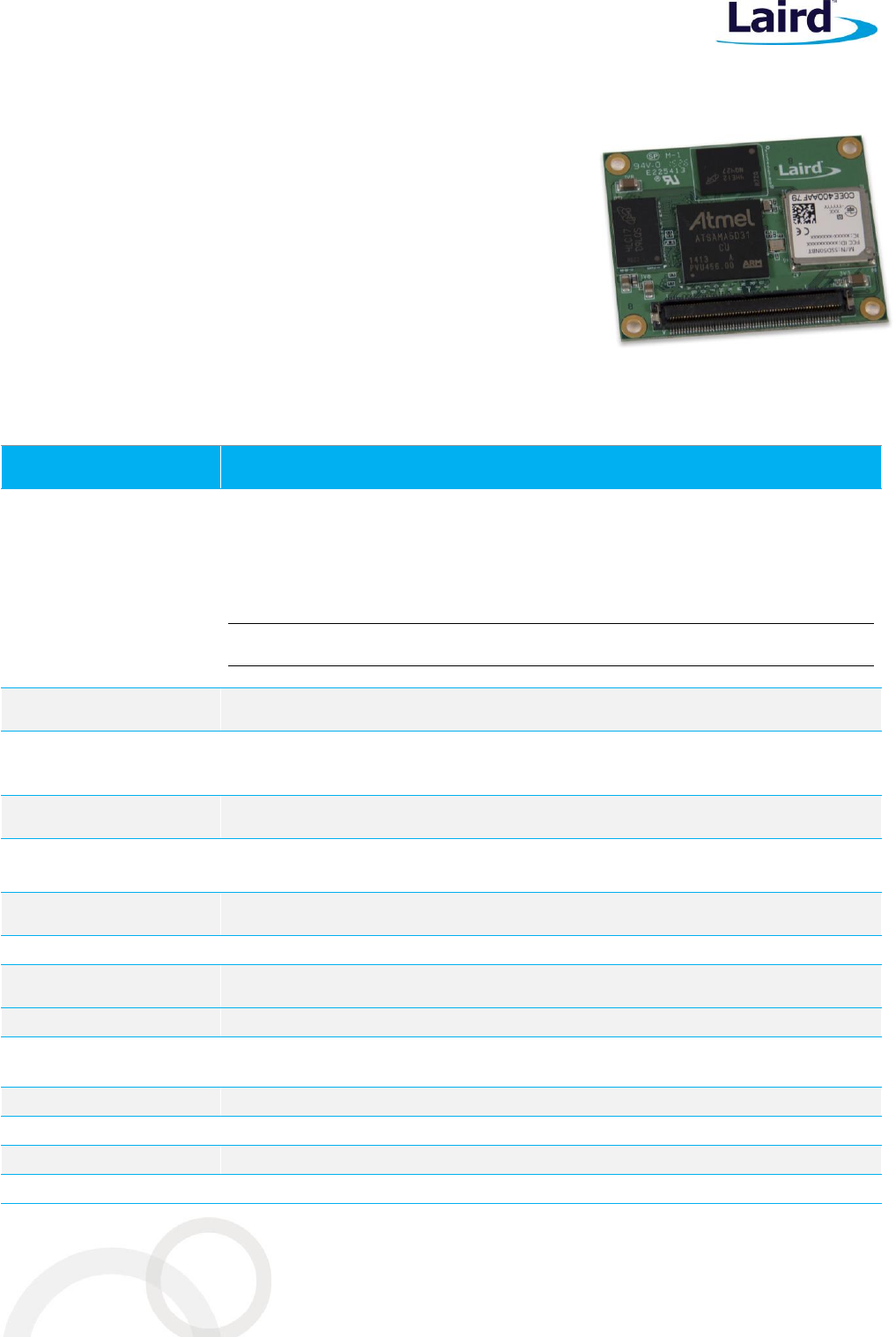
This document describes key hardware aspects of the Laird WB50NBT
wireless bridge module. This document is intended to assist device
manufacturers and related parties with the integration of this module
into their host devices. Data in this document are drawn from a number
of sources including data sheets for the Laird SSD50NBT, QUALCOMM
Atheros AR6004, CSR CSR8811, and Atmel ATSAMA5D31A.
Because the LAIRD WB50NBT is currently in development stage, this
document is preliminary and the information in this document is subject
to change. Please contact Laird to obtain the most recent version of this
document – http://ews-support.lairdtech.com.
SPECIFICATIONS
Feature
Description
Physical Interface
Pitch: 0.5 mm
Kyocera (AVX) – P/N: 245046120600829+
Mating part:
Kyocera (AVX) – P/N:145046120640829+
Stacking height = 4.0 mm
Note: See mounting for mating connector options.
Ethernet Interface
(3.3 V signal level)
10/100 Mbps RMII (Reduced Media Independent Interface)
Asynchronous Serial
Port Interfaces
(3.3 V signal level)
Four-wire UART with hardware handshaking (up to 921,600 baud)
Full mode UART with synchronous clock to support USART interface
SPI Interface
(3.3 V signal level)
Five Wire, Master and Slave modes supported with two chip select
USB Interfaces
One USB device port with high speed/full speed/low speed data rates
Two USB host ports with high speed/full speed/low speed data rates
Two Wire Interface
(3.3V signal level)
Two-wire I2C (Inter-IC)
Debug Interface
Two-wire UART (console) for debug purpose
Digital GPIO
(3.3 V signal level)
Six digital General Purpose I/O (GPIO)
PCM interface
13-bit or 16-bit linear, 8-bit μ-law or A-law companded sample formats
Antenna Interface
2 Hirose U.FL connectors for Wi-Fi (Main/AUX) and BT (AUX only) separately,
50 ohm
Wi-Fi Interface
Qualcomm Atheros AR6004 2x2 802.11 a/b/g/n on 20/40 MHz bandwidth
Bluetooth Interface
CSR CSR8510 Bluetooth 4.0 dual-mode (EDR+BLE)
Processor Chip Set
Atmel 536 MHz ARM 9, P/N ATSAMA5D31A
Operating System
Embedded Linux, 4.1 kernel
WB50NBT
Hardware Integration Guide
Embedded Wireless Solutions Support Center:
http://ews-support.lairdtech.com
www.lairdtech.com/wi-fi
5
© Copyright 2016 Laird. All Rights Reserved
Americas: +1-800-492-2320
Europe: +44-1628-858-940
Hong Kong: +852 2923 0600
Feature
Description
Memory
64 MB LPDDR
Storage
128 MB SLC NAND flash
Input Voltage
Requirements
VDD_BU: +3.3 VDC +/-5% (Backup)
VCC3_3: +3.2V (Min) +3.46V (Max)
Note: Voltage ripple must be less than 30 mV.
Current Consumption
Note: These current
consumption
measurements were
taken using Linux kernel
version 4.1.
Note: Standby refers to
the radio operating while
connected to an AP but
not transmitting or
receiving.
Mode
3.3 V
Average Current
Maximum Current
802.11a
Transmit
TBD
TBD
Receive
TBD
TBD
Standby
TBD
TBD
802.11b
Transmit
TBD
TBD
Receive
TBD
TBD
Standby
TBD
TBD
802.11g
Transmit
TBD
TBD
Receive
TBD
TBD
Standby
TBD
TBD
802.11n (2.4 GHz)
Transmit
TBD
TBD
Receive
TBD
TBD
Standby
TBD
TBD
802.11n (5 GHz)
Transmit
TBD
TBD
Receive
TBD
TBD
Standby
TBD
TBD
Sleep
N/A
TBD
TBD
Operating Temperature
-30° to +85°C (-22°F to 185°F)
Operating Humidity
10 to 90% (non-condensing)
Storage Temperature
-30° to 85°C (-22° to 185°F)
Storage Humidity
10 to 90% (non-condensing)
Maximum Electrostatic
Discharge
Conductive 4KV; Air coupled 8KV follow EN61000-4-2
Length/Width/Thickness
47 mm x 37 mm x 4.9 mm
Note: Length, width, and thickness measurements include the metal
shielding.
Weight
TBD g (TBD oz.)
WB50NBT
Hardware Integration Guide
Embedded Wireless Solutions Support Center:
http://ews-support.lairdtech.com
www.lairdtech.com/wi-fi
6
© Copyright 2016 Laird. All Rights Reserved
Americas: +1-800-492-2320
Europe: +44-1628-858-940
Hong Kong: +852 2923 0600
Feature
Description
Mounting
Connector and through holes.
Refer to Mechanical Specifications for additional information.
Recommended:
Connector:
Pitch: 0.5 mm, 120 pin Kyocera (AVX) P/N:245046120600829+
Mating part:
Kyocera (AVX) P/N:145046120630829+, Stacking height: 3.0 mm
Kyocera (AVX) P/N:145046120635829+, Stacking height: 3.5 mm
Kyocera (AVX) P/N:145046120640829+, Stacking height: 4.0 mm
Kyocera (AVX) P/N:145046120645829+, Stacking height: 4.5 mm
Stand-off for 4.0 mm stacking height:
EMI STOP P/N:F40M20-401126D4BM
http://www.emistop.com; sales08@emistop.com
Wi-Fi Media
Direct Sequence-Spread Spectrum (DSSS)
Complementary Code Keying (CCK)
Orthogonal Frequency Divisional Multiplexing (OFDM)
Wi-Fi Media Access
Protocol
Carrier sense multiple access with collision avoidance (CSMA/CA)
Network Architecture
Infrastructure and ad hoc
Wi-Fi Standards
IEEE 802.11a, 802.11b, 802.11d, 802.11e, 802.11g, 802.11h, 802.11i, 802.11n,
802.11r
Wi-Fi Data Rates
Supported
802.11a (OFDM): 6, 9, 12, 18, 24, 36, 48, 54 Mbps
802.11b (DSSS, CCK): 1, 2, 5.5, 11 Mbps
802.11g (OFDM): 6, 9, 12, 18, 24, 36, 48, 54 Mbps
802.11n (OFDM,HT20,MCS 0-15):
Full Guard Interval: 6.5, 13, 19.5, 26, 39, 52, 58.5, 65, 78, 104, 117 Mbps
Short Guard Interval: 1.2, 14.4, 21.7, 28.9, 29.9, 43.3, 57.8, 65, 72.2, 86.7, 115.6,
130, 144.4 Mbps
Modulation
BPSK @ 1, 6,9, 6.5, 7.2,13 and 14.4 Mbps
QPSK @ 2, 12, 18, 13, 14.4,19.5, 21.7, 26, 28.9, 39,43.3 Mbps
CCK @ 5.5 and 11 Mbps
16-QAM @ 24, 36,26, 29.9,39,43.3,52,57.8,78,86.7 Mbps
64-QAM @ 48,54,52, 57.8, 58.5, 65,72.2,104.0,115.6,117.0,130.0,144.4 Mbps
802.11n Spatial Streams
2X2 MIMO (Multiple Input, Multiple Output)
Regulatory Domain
Support
FCC (Americas, Parts of Asia, and Middle East)
ETSI (Europe, Middle East, Africa, and Parts of Asia)
MIC (Japan) (formerly TELEC)
KC (Korea) (formerly KCC)
2.4 GHz Frequency
Bands
ETSI: 2.4 GHz to 2.483 GHz
FCC: 2.4 GHz to 2.473 GHz
MIC: 2.4 GHz to 2.495 GHz
KC: 2.4 GHz to 2.483 GHz
2.4 GHz Operating
Channels
ETSI: 13 (3 non-overlapping)
FCC: 11 (3 non-overlapping)
MIC: 14 (4 non-overlapping)
KC: 13 (3 non-overlapping)

WB50NBT
Hardware Integration Guide
Embedded Wireless Solutions Support Center:
http://ews-support.lairdtech.com
www.lairdtech.com/wi-fi
7
© Copyright 2016 Laird. All Rights Reserved
Americas: +1-800-492-2320
Europe: +44-1628-858-940
Hong Kong: +852 2923 0600
Feature
Description
5 GHz Frequency Bands
ETSI: 5.15 GHz to 5.35 GHz
5.47 GHz to 5.725 GHz
FCC: 5.15 GHz to 5.35 GHz
5.47 GHz to 5.725 GHz
5.725 GHz to 5.825 GHz
MIC: 5.15 GHz to 5.35 GHz
KC: 5.15 GHz to 5.35 GHz
5.725 GHz to 5.825 GHz
5 GHz Operating
Channels
ETSI: 19 non-overlapping
FCC: 25 non-overlapping
MIC: 8 non-overlapping
KC: 12 non-overlapping
Maximum Transmit
Power
Note: Transmit power on
each channels varies
according to individual
country regulations. All
values for lowest data
rate is nominal, +/-2
dBm.
Others are +/-2.5dBm
Note: HT40 – 40 Mhz-
wide channels
HT20 – 20 MHz-wide
channel
802.11a
6 Mbps
17 dBm (50.1 mW)
54 Mbps
14 dBm (25.1 mW)
802.11b
1 Mbps
17 dBm (50.1 mW)
11 Mbps
17 dBm (50.1 mW)
802.11g
6 Mbps
17 dBm (50.1 mW)
54 Mbps
14 dBm (25.1 mW)
802.11n (2.4 GHz)
6.5 Mbps (MCS0)
17 dBm (50.1 mW)
65 Mbps (MCS7)
13 dBm (20 mW)
802.11n (5 GHz)
6.5 Mbps (MCS0; HT20)
17 dBm (50.1 mW)
65 Mbps (MCS7;HT20)
13 dBm (20 mW)
(MCS0; HT40)
14 dBm (25.1 mW)
(MCS7; HT40)
11 dBm (12.5 mW)
Bluetooth
1 Mbps 6 dBm (3.98 mW)
2 Mbps 6 dBm (3.98 mW)
3 Mbps 3 dBm (1.99 mW)
Typical Receiver
Sensitivity
Note: All values
nominal, +/-3 dBm.
Variant by channels.
802.11a:
6 Mbps
-92 dBm
54 Mbps
-74 dBm (PER <= 10%)
802.11b:
1 Mbps
-94 dBm
11 Mbps
-87 dBm (PER <= 8%)
802.11g:
6 Mbps
-91 dBm
54 Mbps
-74 dBm (PER <= 10%)
802.11n (2.4 GHz)
MCS0 Mbps
-91 dBm
MCS7 Mbps
-71 dBm

WB50NBT
Hardware Integration Guide
Embedded Wireless Solutions Support Center:
http://ews-support.lairdtech.com
www.lairdtech.com/wi-fi
8
© Copyright 2016 Laird. All Rights Reserved
Americas: +1-800-492-2320
Europe: +44-1628-858-940
Hong Kong: +852 2923 0600
Feature
Description
802.11n (5 GHz HT20)
MCS0 Mbps
MCS7 Mbps
-92 dBm
-71 dBm
Bluetooth:
1 Mbps
-83 dBm (1DH1)
2 Mbps
-75 dBm (3DH5)
3 Mbps
-86 dBm
Security
Standards
Wireless Equivalent Privacy (WEP)
Wi-Fi Protected Access (WPA)
IEEE 802.11i (WPA2)
Encryption
Wireless Equivalent Privacy (WEP, RC4 Algorithm)
Temporal Key Integrity Protocol (TKIP, RC4 Algorithm)
Advanced Encryption Standard (AES, Rijndael Algorithm)
Encryption Key Provisioning
Static (40-bit and 128-bit lengths)
Pre-Shared (PSK)
Dynamic
802.1X Extensible Authentication Protocol Types
EAP-FAST
EAP-TLS
EAP-TTLS
PEAP-GTC
PEAP-MSCHAPv2
PEAP-TLS
LEAP
Compliance
Note: Pursuing MIC
and KC certifications is
currently TBD.
ETSI Regulatory Domain
EN 300 328 (Wi-Fi)
EN 300 328 v1.8.1 (BT 2.1)
EN 301 489-1
EN 301 489-17
EN 301 893
EN 60950-1
EU 2002/95/EC (RoHS)
FCC Regulatory Domain
FCC 15.247 DTS – 802.11b/g (Wi-Fi) – 2.4 GHz
FCC 15.407 UNII – 802.11a (Wi-Fi) – 5 GHz
FCC 15.247 DSS – BT 2.1
Industry Canada
RSS-247 – 802.11a/b/g/n (Wi-Fi) – 2.4 GHz, 5.8 GHz, 5.2 GHz, and 5.4 GHz
RSS-247 – BT 2.1
WB50NBT
Hardware Integration Guide
Embedded Wireless Solutions Support Center:
http://ews-support.lairdtech.com
www.lairdtech.com/wi-fi
9
© Copyright 2016 Laird. All Rights Reserved
Americas: +1-800-492-2320
Europe: +44-1628-858-940
Hong Kong: +852 2923 0600
Feature
Description
Certifications
Note: These
certifications are
pending.
Wi-Fi Alliance
802.11a, 802.11b, 802.11g , 802.11n
WPA Enterprise
WPA2 Enterprise
Cisco Compatible Extensions (Version 4)
Warranty
Five Year Limited Lifetime
All specifications are subject to change without notice
Absolute Maximum Ratings
Parameter
Comments
Conditions
Min.
Typ.
Max.
Unit
Input Voltage
3.3V VCC pin
With respect to ground
-0.3
-
3.8
V
I/O pin
-0.3
-
3.8
V
RF input
Maximum RF input from
the antenna port
(reference to 50 ohm)
+10
dBm
Note: Voltage operated over the maximum limit may cause permanent damage to the device. These are
stress ratings only; functional operation of the device at these or any other conditions beyond
those indicated under Recommended Operating Conditions is not implied. Exposure to absolute-
maximum-rated conditions for extended periods may affect device reliability.
Recommended Operating Conditions and DC Power Electrical Characteristics
Parameter
Comments
Conditions
Min.
Typ.
Max.
Unit
Supply Voltage
VCC3_3/VDD BU
Referred to GND
3.2
3.3
3.46
V
Voltage Ripple
VCC3_3/VDD BU
Referred to GND
-
-
30
mV
Recommend Voltage
Supply Current Rating
VCC3_3
VDD_BU
-
-
2000
10
mA
DC Output Current
I/O pin
3.3 V signal level
-
-
8
mA
Voltage Rise Time
At power on
3.3 V / 3.3 VBU
-
-
0.5
ms
Operating Current
WLAN
sub-system
Continuous receive
-
TBD
-
mA
Continuous transmit
-
TBD
-
Bluetooth
sub-system
Continuous receive
-
TBD
-
mA
Continuous transmit
-
TBD
-
CPU
sub-system
Varies with system
load
-
TBD
-
mA
Operating
Temperature
-30
-
+85
°C
WB50NBT
Hardware Integration Guide
Embedded Wireless Solutions Support Center:
http://ews-support.lairdtech.com
www.lairdtech.com/wi-fi
10
© Copyright 2016 Laird. All Rights Reserved
Americas: +1-800-492-2320
Europe: +44-1628-858-940
Hong Kong: +852 2923 0600
Power on Sequence
Notes: Apply the 3.3 V (backup and system) at the same time.
The CPU implements the internal POR (Power-On-Reset) and guarantees that the power sources reach
their target values prior to the release of POR.
DC Electrical Characteristics (3.3 V signal level)
I/O
Indicates whether the signal is input or output state.
PU/PD
Indicates whether Pull-Up, Pull-Down, or nothing is enabled.
ST
Indicates if Schmitt Trigger is enabled.
TR
Tri-state
GPIO [1-6]
PIO, I, PU, ST
LED [0-2]
PIO, I, PU, ST
STAT_0; STAT_1
PIO, I, PU, ST
SHDN
O
NRST
I, PU, ST
BINT
I, PU, ST
WKUP
I,PU, ST
DDM; DDP; HDMA; HDPA; HDMB; HDPB
O, PD
E_TXEN; E_TX [0-1]; E_RXER; E_RX [0-1]; E_MDC;
PIO, I, PU, ST
E_MDIO; E_CRSDV; E_REFCK; E_RST_L; E_INT
TBD
BT_PCM_OUT; BT_PCM_IN; BT_PCM_SYNC; BT_PCM_CLK
TBD
XPABIAS50; XPABIAS51; XPABIAS20; XPABIAS21
TBD
AR6004_GPIO38
TBD
LTE_ACTIVE
TBD
LTE_FRAME_SYNC
TBD
WCN_PRIORITY
TBD
Parameter
Conditions
Min.
Typ.
Max.
Unit
VIL
Input Low-Level Voltage
-0.3
-
0.8
V
VIH
Input High-Level Voltage
2.0
-
3.6
V
VOL
Output Low-Level Voltage
-
-
0.4
V
VOH
Output High-Level Voltage
2.9
-
-
V
VHYS
Schmitt trigger Hysteresis
0.34
-
-
V
RPULLUP
Pull-up/Pull-down Resistance
45
100
130
KΩ
IO
Output Current
-
-
8
mA
WB50NBT
Hardware Integration Guide
Embedded Wireless Solutions Support Center:
http://ews-support.lairdtech.com
www.lairdtech.com/wi-fi
11
© Copyright 2016 Laird. All Rights Reserved
Americas: +1-800-492-2320
Europe: +44-1628-858-940
Hong Kong: +852 2923 0600
PIN DEFINITIONS
Table 1: Pin Definitions
#
Pin Name
Section
I/O
Reference
Description
If Unused
1
GND
-
-
Ground
Must be connected to
GND
2
GPIO_1
GPIO
I/O
VCC3_3
General I/O 1
Leave open
3
SPI_NPCS1
O
VCC3_3
SPI Bus Chip Select 1
Leave open
4
GPIO_2
GPIO
I/O
VCC3_3
General I/O 2
Leave open
5
SPI_NPCS0
O
VCC3_3
SPI Bus Chip Select 0
Leave open
6
GPIO_3
GPIO
I/O
VCC3_3
General I/O 3
Leave open
7
GND
-
-
Ground
Must be connected to
GND
8
GPIO_4
GPIO
I/O
VCC3_3
General I/O 4
Leave open
9
SPI_MOSI
O
VCC3_3
SPI Master Out/Slave In
Leave open
10
DRXD
DBGU
I
VCC3_3
Console/Debug Serial Input
Leave open
11
SPI_MISO
I
VCC3_3
SPI Master In/Slave Out
Leave open
12
DTXD
DBGU
O
VCC3_3
Console/Debug Serial Output
Leave open
13
GND
-
-
Ground
Must be connected to
GND
14
GPIO_5
GPIO
I/O
VCC3_3
General I/O 5
Leave open
15
SPI_CLK
O
VCC3_3
SPI Programming Clock
Master – O; Slave – I
Leave open
16
GPIO_6
GPIO
I/O
VCC3_3
General I/O 6
Leave open
17
GND
-
-
Ground
Must be connected to
GND
18
LED_0
O
VCC3_3
LED Indicator (WLAN Act)
(IO = 8 Ma maximum)
Leave open
19
E_REFCK
I
VCC3_3
Ethernet Reference Clock
(50 MHz maximum)
Leave open
20
LED_1
O
VCC3_3
LED Indicator (TBD)
(IO = 8 Ma maximum)
Leave open
21
GND
-
-
Ground
Must be connected to
GND
22
LED_2
O
VCC3_3
LED Indicator (TBD)
(IO = 8 Ma maximum)
Leave open
23
E_TXD0
O
VCC3_3
Ethernet Data Output 0
Leave open
24
STAT_0
O
VCC3_3
Status High while system in reset,
bootloader, or OS boot;
Low when OS is up
Leave open
25
E_TXD1
O
VCC3_3
Ethernet Data Output 1
Leave open

WB50NBT
Hardware Integration Guide
Embedded Wireless Solutions Support Center:
http://ews-support.lairdtech.com
www.lairdtech.com/wi-fi
12
© Copyright 2016 Laird. All Rights Reserved
Americas: +1-800-492-2320
Europe: +44-1628-858-940
Hong Kong: +852 2923 0600
#
Pin Name
Section
I/O
Reference
Description
If Unused
26
STAT_1
O
VCC3_3
Status High when system is running;
Low when system is in suspend state
Leave open
27
GND
-
-
Ground
Must be connected to
GND
28
PWDN
(SHDN)
I
VDD_BU
Power down the Module
Active low
100K Pull High
29
E_RXD0
I
VCC3_3
Ethernet Data Input 0
Leave open
30
NRST
(RESET)
I
VCC3_3
HW System Reset
Active low
100K Pull High
31
E_RXD1
I
VCC3_3
Ethernet Data Input 1
Leave open
32
GND
-
-
Ground
Must be connected to
GND
33
GND
-
-
Ground
Must be connected to
GND
34
TW_D
I/O
VCC3_3
Two-wire Serial Data
Leave open
35
E_TXEN
O
VCC3_3
Ethernet Transmit Enable
Leave open
36
TW_CLK
I/O
VCC3_3
Two-wire Serial Clock
Leave open
37
E_CRSDV
I
VCC3_3
Ethernet Carrier Sense and
Valid Data
Leave open
38
GND
-
-
Ground
Must be connected to
GND
39
E_RXER
I
VCC3_3
Ethernet Receive Error
Leave open
40
TXD_1
O
VCC3_3
Serial UART1 Transmit Data 1
Leave open
41
E_RST_L
O
VCC3_3
Ethernet Reset
Leave open
42
RXD_1
I
VCC3_3
Serial UART1 Receive Data 1
Leave open
43
E_MDC
O
VCC3_3
Ethernet Management Data Clock
Leave open
44
CTS_1
I
VCC3_3
UART1 Interface, clear-to-send,
active low
Leave open
45
E_MDIO
I/O
VCC3_3
Ethernet Management Data I/O
Leave open
46
RTS_1
O
VCC3_3
UART1 Interface, request-to-send,
active low
Leave open
47
E_INT
I
VCC3_3
Ethernet Interrupt Request
Leave open
48
GND
-
-
Ground
Must be connected to
GND
49
GND
-
-
Ground
Must be connected to
GND
50
CTS_0
I
VCC3_3
UART0 Interface, clear-to-send,
active low
Leave open
51
MC_DA3
I/O
VCC3_3
SDIO Multimedia Card Data 3
Leave open
52
RTS_0
O
VCC3_3
UART0 Interface, request-to-send,
active low
Leave open

WB50NBT
Hardware Integration Guide
Embedded Wireless Solutions Support Center:
http://ews-support.lairdtech.com
www.lairdtech.com/wi-fi
13
© Copyright 2016 Laird. All Rights Reserved
Americas: +1-800-492-2320
Europe: +44-1628-858-940
Hong Kong: +852 2923 0600
#
Pin Name
Section
I/O
Reference
Description
If Unused
53
MC_DA2
I/O
VCC3_3
SDIO Multimedia Card Data 2
Leave open
54
DSR_0
I
VCC3_3
UART0 Interface, Data Set Ready
10K Pull High
55
GND
-
-
Ground
Must be connected to
GND
56
DTR_0
O
VCC3_3
UART0 Interface, Data Terminal Ready
Leave open
57
MC_DA1
I/O
VCC3_3
SDIO Multimedia Card Data 1
Leave open
58
RI_0
I
VCC3_3
UART0 Ring Indicator 1
10K Pull High
59
MC_DA0
I/O
VCC3_3
SDIO Multimedia Card Data 0
Leave open
60
DCD_0
I
VCC3_3
UART0 Data Carrier Detect
10K Pull High
61
GND
-
-
Ground
Must be connected to
GND
62
GND
-
-
Ground
Must be connected to
GND
63
MC_CLK
O
VCC3_3
SDIO Multimedia Card Clock
Leave open
64
S_CLK_0
I/O
VCC3_3
UART0 Serial Clock
Leave open
65
GND
-
-
Ground
Must be connected to
GND
66
TXD_0
O
VCC3_3
UART0 Serial Output
Leave open
67
MC_CDA
I/O
VCC3_3
SDIO Multimedia Card Command
Leave open
68
RXD_0
I
VCC3_3
UART0 Serial Input
Leave open
69
GND
-
-
Ground
Must be connected to
GND
70
GND
-
-
Ground
Must be connected to
GND
71
N/C
-
-
No Connection
Leave open
72
B_INT
(IRQ)
I
VCC3_3
External Bus Interface
Interrupt Request
100K Pull High
73
N/C
-
-
No Connection
Leave open
74
WKUP
I
VDD_BU
Interrupt Signal to wake up module;
active low
100K Pull High
75
N/C
-
-
No Connection
Leave open
76
GND
-
-
Ground
Must be connected to
GND
77
GND
-
-
Ground
Must be connected to
GND
78
XPABIAS50
O
VCC3_3
External 5GHz booster control signal to
turn on the PA for Chain 0.
Leave open
79
N/C
-
-
No Connection
Leave open
80
XPABIAS51
O
VCC3_3
External 5GHz booster control signal to
turn on the PA for Chain 1
Leave open
WB50NBT
Hardware Integration Guide
Embedded Wireless Solutions Support Center:
http://ews-support.lairdtech.com
www.lairdtech.com/wi-fi
14
© Copyright 2016 Laird. All Rights Reserved
Americas: +1-800-492-2320
Europe: +44-1628-858-940
Hong Kong: +852 2923 0600
#
Pin Name
Section
I/O
Reference
Description
If Unused
81
N/C
-
-
No Connection
Leave open
82
GND
-
-
Ground
Must be connected to
GND
83
N/C
-
-
No Connection
Leave open
84
XPABIAS20
O
VCC3_3
External 2.4GHz booster control signal
to turn on the PA for Chain 0
Leave open
85
GND
-
-
Ground
Must be connected to
GND
86
XPABIAS21
O
VCC3_3
External 2.4GHz booster control signal
to turn on the PA for Chain 1
Leave open
87
GPIO_DPU CNTRL
O
VCC3_3
USB device pull-up resistor enable;
active high
Leave open
88
BT_PCM_SYN_C
O
VCC3_3
PCM Sync
Leave open
89
DBUSSENSE
I
VCC3_3
USB device bus sense signal from
peripheral to host;
active low
Leave open
90
BT_PCM_IN
I
VCC3_3
PCM Signal Input
Leave open
91
GND
-
-
Ground
Must be connected to
GND
92
BT_PCM_OUT
O
VCC3_3
PCM Signal Output
Leave open
93
DDM
I/O
-
USB Device Data Negative
Leave open
94
GND
-
-
Ground
Must be connected to
GND
95
DDP
I/O
-
USB Device Data Positive
Leave open
96
BT_PCM_CLK
I/O
VCC3_3
PCM Clock Signal
Leave open
97
GND
-
-
Ground
Must be connected to
GND
98
AR6004_GPIO_38
I/O
VCC3_3
Reserved for feature LTE coexistence ;
Reserved for WiFi LED indicator, Active
High
Leave open
99
HDMA
I/O
-
USB Host A Data Negative
Leave open
100
GND
-
-
Ground
Must be connected to
GND
101
HDPA
I/O
-
USB Host A Data Positive
Leave open
102
LTE_COEX3
I/O
VCC3_3
Reserved for LTE coexistence
Leave open
103
GND
-
-
Ground
Must be connected to
GND
104
LTE_ACTIVE
I/O
VCC3_3
Reserved for LTE coexistence
Leave open
105
HDMB
I/O
-
USB Host B Data Negative
Leave open
106
LTE_FRAME_SYNC
I/O
VCC3_3
Reserved for feature usage
Leave open
107
HDPB
I/O
-
USB Host B Data Positive
Leave open
WB50NBT
Hardware Integration Guide
Embedded Wireless Solutions Support Center:
http://ews-support.lairdtech.com
www.lairdtech.com/wi-fi
15
© Copyright 2016 Laird. All Rights Reserved
Americas: +1-800-492-2320
Europe: +44-1628-858-940
Hong Kong: +852 2923 0600
#
Pin Name
Section
I/O
Reference
Description
If Unused
108
WCN_PRIORITY
I/O
VCC3_3
Reserved for LTE coexistence
Leave open
109
GND
-
-
Ground
Must be connected to
GND
110
GND
-
-
Ground
Must be connected to
GND
111
GND
-
-
Ground
Must be connected to
GND
112
DEBUG_UART_TXD
O
VCC3_3
WLAN debug UART TXD output.
Leave open
113
GND
-
-
Ground
Must be connected to
GND
114
GND
-
-
Ground
Must be connected to
GND
115
VDD_BU
-
-
Module Back-up Power 3.3V
116
GND
-
-
Ground
Must be connected to
GND
117
VCC3_3
-
-
3.3V Module Power
118
VCC3_3
-
-
3.3V Module Power
119
VCC3_3
-
-
3.3V Module Power
120
VCC3_3
-
-
3.3V Module Power
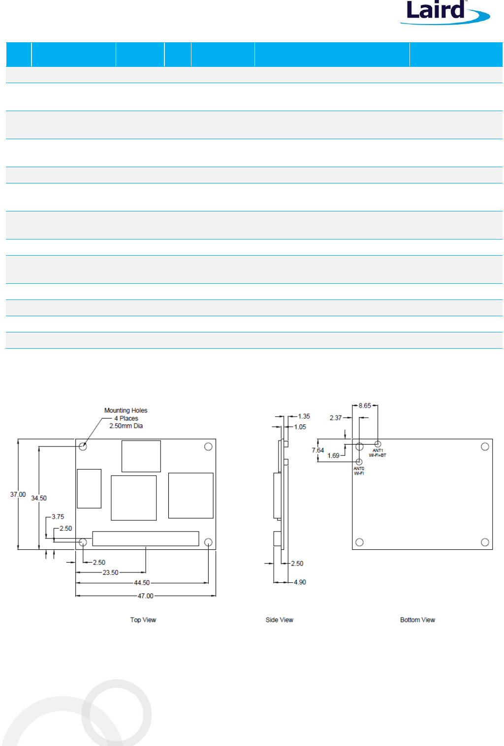
MECHANICAL SPECIFICATION
Figure 1: WB50NBT mechanical drawing
WB50NBT
Hardware Integration Guide
Embedded Wireless Solutions Support Center:
http://ews-support.lairdtech.com
www.lairdtech.com/wi-fi
16
© Copyright 2016 Laird. All Rights Reserved
Americas: +1-800-492-2320
Europe: +44-1628-858-940
Hong Kong: +852 2923 0600
REGULATORY
Certified Antennas
The WB50NBT will be tested to the regulatory standards defined in the Certifications section of the
Specifications table above. Laird plans to conduct these tests with the following antennas:
Model
Type
Connector
2400~2483.5MHz
5150~5250MHz 5250~5350MHz
5470~5725MHz 5725~5850MHz
Laird MAF94051
Dipole
RP-SMA
2.1 dBi (2.4-2.5 GHz), 2.4 dBi (4.9 GHz)
2.6 dBi (5.25 GHz), 3.4 dBi (5.875 GHz)
Laird/NanoBlade-IP04
PCB
Dipole
IPEX MHF
2 dBi (2.4-2.5 GHz),
3.9 dBi (5.15-5.35 GHz), 4 dBi (5.6 GHz)
Laird/MAF95310 Mini Nano Blade
Flex
PCB
Dipole
IPEX MHF
2.79 dBi (2.4 GHz), 3.38 dBi (5 GHz)
Laird/NanoBlue-IP04
PCB
Dipole
IPEX MHF
2 dBi (2.4 GHz only)
Ethertronics/WLAN_1000146
Isolated
Magnetic
Dipole
IPEX MHF
2.5 dBi (2.390-2.490 GHz),
3.5 dBi (4.900-5.100, 5.150-5.350,
5.70-5.900 GHz)
FCC AND IC REGULATORY
Model
US/FCC
CANADA/IC
WB50NBT
SQG-WB50NBT
3147A-WB50NBT
The WB50NBT is designed to pass certification with the antenna listed below. The required antenna impedance
is 50 ohms.
Model
Type
Connector
Peak gain ( dBi )
2400~2483.5
MHz
5150~5250
MHz
5250~5350
MHz
5470~5725
MHz
5725~5850
MHz
Laird
MAF94051
Dipole
RP-SMA
2.1 dBi
2.4 dBi
2.6 dBi
3.4 dBi
Laird
NanoBlade-IP04
PCB Dipole
IPEX MHF
2 dBi
3.9 dBi
4 dBi
Laird
MAF95310 Mini
NanoBlade Flex
PCB Dipole
IPEX MHF
2.79 dBi
3.38 dBi
Laird
NanoBlue-IP04
PCB Dipole
IPEX MHF
2dBi
_
Ethertronics
WLAN_1000146
Isolated
Magnetic
Dipole
IPEX MHF
2.5dBi
3.5 dBi

WB50NBT
Hardware Integration Guide
Embedded Wireless Solutions Support Center:
http://ews-support.lairdtech.com
www.lairdtech.com/wi-fi
17
© Copyright 2016 Laird. All Rights Reserved
Americas: +1-800-492-2320
Europe: +44-1628-858-940
Hong Kong: +852 2923 0600
FCC
Federal Communication Commission Interference Statement
This equipment has been tested and found to comply with the limits for a Class B digital device, pursuant to Part
15 of the FCC Rules. These limits are designed to provide reasonable protection against harmful interference in a
residential installation. This equipment generates, uses and can radiate radio frequency energy and, if not
installed and used in accordance with the instructions, may cause harmful interference to radio
communications. However, there is no guarantee that interference will not occur in a particular installation. If
this equipment does cause harmful interference to radio or television reception, which can be determined by
turning the equipment off and on, the user is encouraged to try to correct the interference by one of the
following measures:
Reorient or relocate the receiving antenna.
Increase the separation between the equipment and receiver.
Connect the equipment into an outlet on a circuit different from that to which the receiver is connected.
Consult the dealer or an experienced radio/TV technician for help.
FCC Caution:
Any changes or modifications not expressly approved by the party responsible for compliance could void the
user's authority to operate this equipment.
This device complies with Part 15 of the FCC Rules. Operation is subject to the following two conditions: (1) This
device may not cause harmful interference, and (2) this device must accept any interference received, including
interference that may cause undesired operation.
Important Note:
Radiation Exposure Statement
This equipment complies with FCC radiation exposure limits set forth for an uncontrolled environment. This
equipment should be installed and operated with minimum distance 20cm between the radiator and your body.
This transmitter must not be co-located or operating in conjunction with any other antenna or transmitter.
Country Code selection feature to be disabled for products marketed to the US/Canada.
This device is intended only for OEM integrators under the following conditions:
The antenna must be installed such that 20 cm is maintained between the antenna and users, and
The transmitter module may not be co-located with any other transmitter or antenna,
For all products market in US, OEM has to limit the operation channels in CH1 to CH11 for 2.4G band by
supplied firmware programming tool. OEM shall not supply any tool or info to the end-user regarding to
Regulatory Domain change.
As long as the three conditions above are met, further transmitter testing will not be required. However, the
OEM integrator is still responsible for testing their end-product for any additional compliance requirements
required with this module installed.

WB50NBT
Hardware Integration Guide
Embedded Wireless Solutions Support Center:
http://ews-support.lairdtech.com
www.lairdtech.com/wi-fi
18
© Copyright 2016 Laird. All Rights Reserved
Americas: +1-800-492-2320
Europe: +44-1628-858-940
Hong Kong: +852 2923 0600
Important Note:
In the event that these conditions cannot be met (for example certain laptop configurations or co-location with
another transmitter), then the FCC authorization is no longer considered valid and the FCC ID cannot be used on
the final product. In these circumstances, the OEM integrator will be responsible for re-evaluating the end
product (including the transmitter) and obtaining a separate FCC authorization.
End Product Labeling
This transmitter module is authorized only for use in device where the antenna may be installed such that 20 cm
may be maintained between the antenna and users. The final end product must be labeled in a visible area with
the following for the WB50NBT: Contains FCC ID: SQG-WB50NBT.
Manual Information to the End User
The OEM integrator has to be aware not to provide information to the end user regarding how to install or
remove this RF module in the user’s manual of the end product which integrates this module.
The end user manual shall include all required regulatory information/warning as show in this manual.
Industry Canada
Industry Canada Statement
This device complies with Industry Canada’s license-exempt RSSs. Operation is subject to the following two
conditions:
This device may not cause interference; and
This device must accept any interference, including interference that may cause undesired operation of
the device.
Le présent appareil est conforme aux CNR d’Industrie Canada applicables aux appareils radio exempts de licence.
L’exploitation est autorisée aux deux conditions suivantes:
l’appareil ne doit pas produire de brouillage;
l’utilisateur de l’appareil doit accepter tout brouillage radioélectrique subi, même si le brouillage est
susceptible d’en compromettre le fonctionnement.
This radio transmitter (WB5050NBT – IC: 3147A-WB50NBT) has been approved by Industry Canada to operate
with the antenna types listed below with the maximum permissible gain indicated. Antenna types not included in
this list, having a gain greater than the maximum gain indicated for that type, are strictly prohibited for use with
this device.
Le présent émetteur radio (WB5050NBT – IC: 3147A-WB50NBT) a été approuvé par Industrie Canada pour
fonctionner avec les types d'antenne énumérés ci-dessous et ayant un gain admissible maximal. Les types
d'antenne non inclus dans cette liste, et dont le gain est supérieur au gain maximal indiqué, sont strictement
interdits pour l'exploitation de l'émetteur.

WB50NBT
Hardware Integration Guide
Embedded Wireless Solutions Support Center:
http://ews-support.lairdtech.com
www.lairdtech.com/wi-fi
19
© Copyright 2016 Laird. All Rights Reserved
Americas: +1-800-492-2320
Europe: +44-1628-858-940
Hong Kong: +852 2923 0600
Antenna Information
Model
Type
Connector
Peak gain ( dBi )
2400~2483.5
MHz
5150~5250
MHz
5250~5350
MHz
5470~5725
MHz
5725~5850
MHz
Laird
MAF94051
Dipole
RP-SMA
2.1 dBi
2.4 dBi
2.6 dBi
3.4 dBi
Laird
NanoBlade-IP04
PCB Dipole
IPEX MHF
2 dBi
3.9 dBi
4 dBi
Laird
MAF95310 Mini
NanoBlade Flex
PCB Dipole
IPEX MHF
2.79 dBi
3.38 dBi
Laird
NanoBlue-IP04
PCB Dipole
IPEX MHF
2dBi
_
Ethertronics
WLAN_1000146
Isolated
Magnetic
Dipole
IPEX MHF
2.5dBi
3.5 dBi
Caution:
(i) The device for operation in the band 5150–5250 MHz is only for indoor use to reduce the potential for
harmful interference to co-channel mobile satellite systems;
(ii) For devices with detachable antenna(s), the maximum antenna gain permitted for devices in the bands 5250-
5350 MHz and 5470-5725 MHz shall be such that the equipment still complies with the EIRP limit;
(iii) For devices with detachable antenna(s), the maximum antenna gain permitted for devices in the band 5725-
5850 MHz shall be such that the equipment still complies with the EIRP limits specified for point-to-point and
non-point-to-point operation as appropriate; and
Operations in the 5.25-5.35GHz band are restricted to indoor usage only.
Avertissement:
(i) les dispositifs fonctionnant dans la bande de 5150 à 5250MHz sont réservés uniquement pour une utilisation
à l'intérieur afin de réduire les risques de brouillage préjudiciable aux systèmes de satellites mobiles utilisant les
mêmes canaux;
(ii) pour les dispositifs munis d'antennes amovibles, le gain maximal d'antenne permis pour les dispositifs
utilisant les bandes de 5250 à 5350MHz et de 5470 à 5725 MHz doit être conforme à la limite de la p.i.r.e;
(iii) pour les dispositifs munis d'antennes amovibles, le gain maximal d'antenne permis (pour les dispositifs
utilisant la bande de 5725 à 5850 MHz) doit être conforme à la limite de la p.i.r.e. spécifiée pour l'exploitation
point à point et l'exploitation non point à point, selon le cas;
Les opérations dans la bande de 5.25-5.35GHz sont limités à un usage intérieur seulement.
Radiation Exposure Statement
This equipment complies with Canada radiation exposure limits set forth for an uncontrolled environment. This
equipment should be installed and operated with minimum distance 20cm between the radiator & your body.

WB50NBT
Hardware Integration Guide
Embedded Wireless Solutions Support Center:
http://ews-support.lairdtech.com
www.lairdtech.com/wi-fi
20
© Copyright 2016 Laird. All Rights Reserved
Americas: +1-800-492-2320
Europe: +44-1628-858-940
Hong Kong: +852 2923 0600
Déclaration d'exposition aux radiations
Cet équipement est conforme Canada limites d'exposition aux radiations dans un environnement non contrôlé.
Cet équipement doit être installé et utilisé à distance minimum de 20cm entre le radiateur et votre corps.
This device is intended only for OEM integrators under the following condition:
The transmitter module may not be co-located with any other transmitter or antenna.
As long as the condition above is met, further transmitter test will not be required. However, the OEM
integrator is still responsible for testing their end-product for any additional compliance requirements required
with this module installed.
Cet appareil est conçu uniquement pour les intégrateurs OEM dans les conditions suivantes:
Le module émetteur peut ne pas être coïmplanté avec un autre émetteur ou antenne.
Tant que les 1 condition ci-dessus sont remplies, des essais supplémentaires sur l'émetteur ne seront pas
nécessaires. Toutefois, l'intégrateur OEM est toujours responsable des essais sur son produit final pour toutes
exigences de conformité supplémentaires requis pour ce module installé.
Important Note:
In the event that these conditions cannot be met (for example certain laptop configurations or co-location with
another transmitter), then the Canada authorization is no longer considered valid and the IC ID cannot be used
on the final product. In these circumstances, the OEM integrator will be responsible for re-evaluating the end
product (including the transmitter) and obtaining a separate Canada authorization.
Note Importante:
Dans le cas où ces conditions ne peuvent être satisfaites (par exemple pour certaines configurations
d'ordinateur portable ou de certaines co-localisation avec un autre émetteur), l'autorisation du Canada n'est
plus considéré comme valide et l'ID IC ne peut pas être utilisé sur le produit final. Dans ces circonstances,
l'intégrateur OEM sera chargé de réévaluer le produit final (y compris l'émetteur) et l'obtention d'une
autorisation distincte au Canada.
End Product Labeling
The final end product must be labeled in a visible area with the following for the WB5050NBT – IC: 3147A-
WB50NBT.
Plaque signalétique du produit final
Le produit final doit être étiqueté dans un endroit visible avec l'inscription suivante: WB50NBT – Contient des IC:
3147A-WB50NBT.
Manual Information to the End User
The OEM integrator has to be aware not to provide information to the end user regarding how to install or
remove this RF module in the user’s manual of the end product which integrates this module.
The end user manual shall include all required regulatory information/warning as show in this manual.
WB50NBT
Hardware Integration Guide
Embedded Wireless Solutions Support Center:
http://ews-support.lairdtech.com
www.lairdtech.com/wi-fi
21
© Copyright 2016 Laird. All Rights Reserved
Americas: +1-800-492-2320
Europe: +44-1628-858-940
Hong Kong: +852 2923 0600
Manuel d'information à l'utilisateur final
L'intégrateur OEM doit être conscient de ne pas fournir des informations à l'utilisateur final quant à la façon
d'installer ou de supprimer ce module RF dans le manuel de l'utilisateur du produit final qui intègre ce module.
Le manuel de l'utilisateur final doit inclure toutes les informations réglementaires requises et avertissements
comme indiqué dans ce manuel.
EUROPEAN UNION REGULATORY
The WB50NBT has been tested for compliance with relevant standards for the EU market. The WB50NBT
module was tested with antennas listed below.
Model
Type
Connector
2400~2483.5MHz
5150~5250MHz 5250~5350MHz
5470~5725MHz 5725~5850MHz
Laird MAF94051
Dipole
RP-SMA
2.1 dBi (2.4-2.5 GHz), 2.4 dBi (4.9 GHz)
2.6 dBi (5.25 GHz), 3.4 dBi (5.875 GHz)
Laird/NanoBlade-IP04
PCB
Dipole
IPEX MHF
2 dBi (2.4-2.5 GHz),
3.9 dBi (5.15-5.35 GHz), 4 dBi (5.6 GHz)
Laird/MAF95310 Mini Nano Blade
Flex
PCB
Dipole
IPEX MHF
2.79 dBi (2.4 GHz), 3.38 dBi (5 GHz)
Laird/NanoBlue-IP04
PCB
Dipole
IPEX MHF
2 dBi (2.4 GHz only)
Ethertronics/WLAN_1000146
Isolated
Magnetic
Dipole
IPEX MHF
2.5 dBi (2.390-2.490 GHz),
3.5 dBi (4.900-5.100, 5.150-5.350,
5.70-5.900 GHz)
The OEM should consult with a qualified test house before entering their device into an EU member country to
make sure all regulatory requirements have been met for their complete device.
Reference the Declaration of Conformities listed below for a full list of the standards that the modules were
tested to. Test reports are available upon request.
EU DECLARATIONS OF CONFORMITY
WB50NBT
Manufacturer:
Laird
Product:
WB50NBT
EU Directive:
RTTE 1995/5/EC
Conformity Assessment:
Annex IV
Reference standards used for presumption of conformity:
Article Number
Requirement
Reference standard(s)
3.1a
Health and Safety
EN60950-1:2006+A11:2009+A1:2010+A12:2011
3.1b
Protection requirements with respect
to electromagnetic compatibility
EN 301 489-1 V1.9.2 (2011-09)
EN 301 489-17 V2.2.1 (2012-09)
WB50NBT
Hardware Integration Guide
Embedded Wireless Solutions Support Center:
http://ews-support.lairdtech.com
www.lairdtech.com/wi-fi
22
© Copyright 2016 Laird. All Rights Reserved
Americas: +1-800-492-2320
Europe: +44-1628-858-940
Hong Kong: +852 2923 0600
Article Number
Requirement
Reference standard(s)
Emissions:
EN55022:2006/A1:2007 (Class B)
Immunity:
EN61000-4-2:2009
EN61000-4-3:2006/A1:2008/A2:2010
3.2
Means of the efficient use of the
radio frequency spectrum
EN 300 328 V1.8.1 (2012-06)
EN 301 893 v1.8.1
ORDERING INFORMATION
Product Name
Description
Part Number
WB50NBT
802.11a/b/g/n - BT 4.0 Communications Subsystem
WH-WB50NBT
DVK-WB50NBT
Development Breakout board WB50NBT module included
DVK-WB50NBT
General Comments
This is a preliminary datasheet. Please check with Laird for the latest information before commencing a design. If
in doubt, ask.
Česky
[Czech]
[Jméno výrobce] tímto prohlašuje, že tento [typ zařízení] je ve shodě se základními požadavky
a dalšími příslušnými ustanoveními směrnice 1999/5/ES.
Dansk
[Danish]
Undertegnede [fabrikantens navn] erklærer herved, at følgende udstyr [udstyrets
typebetegnelse] overholder de væsentlige krav og øvrige relevante krav i direktiv 1999/5/EF.
Deutsch
[German]
Hiermit erklärt [Name des Herstellers], dass sich das Gerät [Gerätetyp] in Übereinstimmung
mit den grundlegenden Anforderungen und den übrigen einschlägigen Bestimmungen der
Richtlinie 1999/5/EG befindet.
Eesti
[Estonian]
Käesolevaga kinnitab [tootja nimi = name of manufacturer] seadme [seadme tüüp = type of
equipment] vastavust direktiivi 1999/5/EÜ põhinõuetele ja nimetatud direktiivist tulenevatele
teistele asjakohastele sätetele.
English
Hereby, [name of manufacturer], declares that this [type of equipment] is in compliance with
the essential requirements and other relevant provisions of Directive 1999/5/EC.
Español
[Spanish]
Por medio de la presente [nombre del fabricante] declara que el [clase de equipo] cumple con
los requisitos esenciales y cualesquiera otras disposiciones aplicables o exigibles de la Directiva
1999/5/CE.
Ελληνική
[Greek]
ΜΕ ΤΗΝ ΠΑΡΟΥΣΑ [name of manufacturer] ΔΗΛΩΝΕΙ ΟΤΙ [type of equipment]
ΣΥΜΜΟΡΦΩΝΕΤΑΙ ΠΡΟΣ ΤΙΣ ΟΥΣΙΩΔΕΙΣ ΑΠΑΙΤΗΣΕΙΣ ΚΑΙ ΤΙΣ ΛΟΙΠΕΣ ΣΧΕΤΙΚΕΣ
ΔΙΑΤΑΞΕΙΣ ΤΗΣ ΟΔΗΓΙΑΣ 1999/5/ΕΚ.
Français
[French]
Par la présente [nom du fabricant] déclare que l'appareil [type d'appareil] est conforme aux
exigences essentielles et aux autres dispositions pertinentes de la directive 1999/5/CE.
Italiano
[Italian]
Con la presente [nome del costruttore] dichiara che questo [tipo di apparecchio] è conforme ai
requisiti essenziali ed alle altre disposizioni pertinenti stabilite dalla direttiva 1999/5/CE.
Latviski
[Latvian]
Aršo[name of manufacturer /izgatavotājanosaukums] deklarē, ka[type of equipment / iekārtas
tips]atbilstDirektīvas 1999/5/EK būtiskajāmprasībām un citiemar to saistītajiemnoteikumiem.
WB50NBT
Hardware Integration Guide
Embedded Wireless Solutions Support Center:
http://ews-support.lairdtech.com
www.lairdtech.com/wi-fi
23
© Copyright 2016 Laird. All Rights Reserved
Americas: +1-800-492-2320
Europe: +44-1628-858-940
Hong Kong: +852 2923 0600
Lietuvių
[Lithuanian]
Šiuo [manufacturer name] deklaruoja, kad šis [equipment type] atitinka esminius reikalavimus
ir kitas 1999/5/EB Direktyvos nuostatas.
Nederlands
[Dutch]
Hierbij verklaart [naam van de fabrikant] dat het toestel [type van toestel] in overeenstemming
is met de essentiële eisen en de andere relevante bepalingen van richtlijn 1999/5/EG.
Malti
[Maltese]
Hawnhekk, [isem tal-manifattur], jiddikjara li dan [il-mudel tal-prodott] jikkonforma mal-
ħtiġijiet essenzjali u ma provvedimenti oħrajn relevanti li hemm fid-Dirrettiva 1999/5/EC.
Magyar
[Hungarian]
Alulírott, [gyártó neve] nyilatkozom, hogy a [... típus]megfelel a vonatkozó alapvetõ
követelményeknek és az 1999/5/EC irányelv egyéb elõírásainak.
Polski
[Polish]
Niniejszym [nazwa producenta] oświadcza, że [nazwa wyrobu] jest zgodny z zasadniczymi
wymogami oraz pozostałymi stosownymi postanowieniami Dyrektywy 1999/5/EC.
Português
[Portuguese]
[Nome do fabricante] declara que este [tipo de equipamento] está conforme com os requisitos
essenciais e outras disposições da Directiva 1999/5/CE.
Slovensko
[Slovenian]
[Ime proizvajalca] izjavlja, da je ta [tip opreme] v skladu z bistvenimi zahtevami in ostalimi
relevantnimi določili direktive 1999/5/ES.
Slovensky
[Slovak]
[Menovýrobcu]týmtovyhlasuje, že[typzariadenia]spĺňazákladnépožiadavky a
všetkypríslušnéustanoveniaSmernice 1999/5/ES.
Suomi
[Finnish]
[Valmistaja = manufacturer] vakuuttaa täten että [type of equipment = laitteen tyyppimerkintä]
tyyppinen laite on direktiivin 1999/5/EY oleellisten vaatimusten ja sitä koskevien direktiivin
muiden ehtojen mukainen.
Svenska
[Swedish]
Härmed intygar [företag] att denna [utrustningstyp] står I överensstämmelse med de väsentliga
egenskapskrav och övriga relevanta bestämmelser som framgår av direktiv 1999/5/EG.
Labeling Requirements
The final end product must be labeled in a visible area with the following notice: