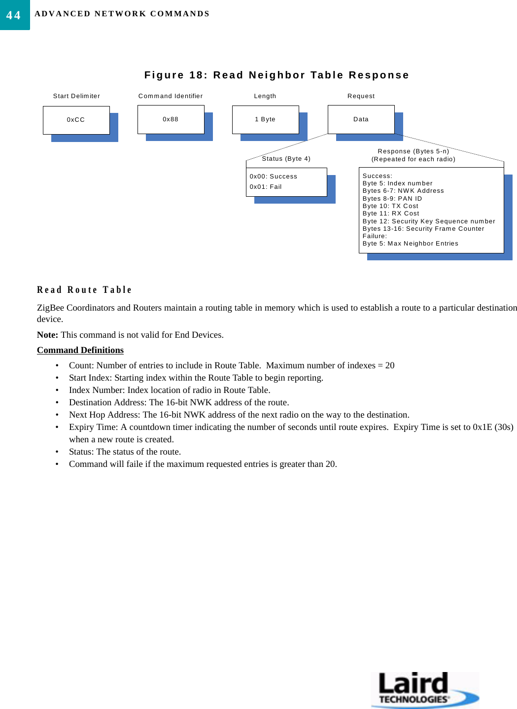
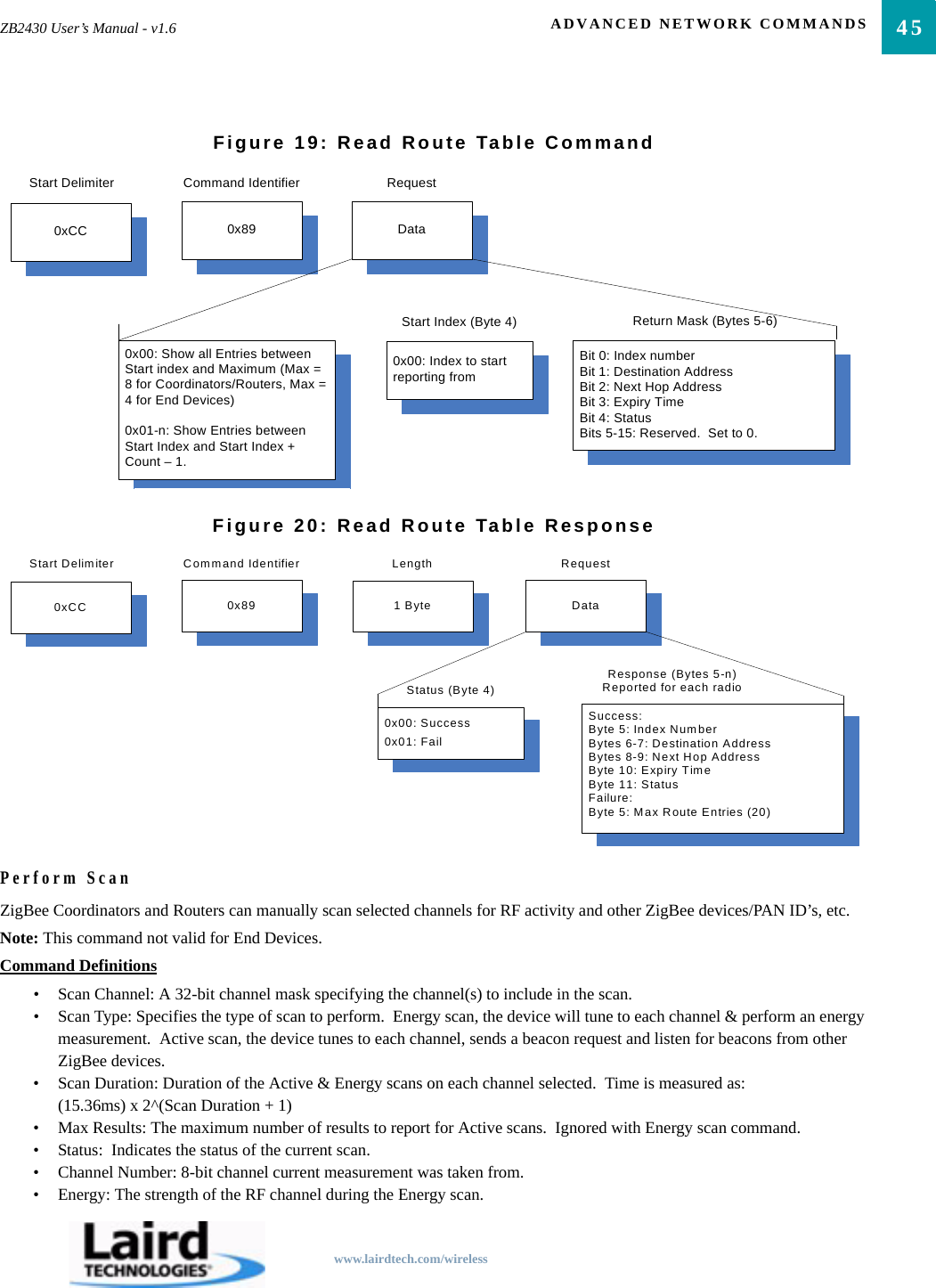
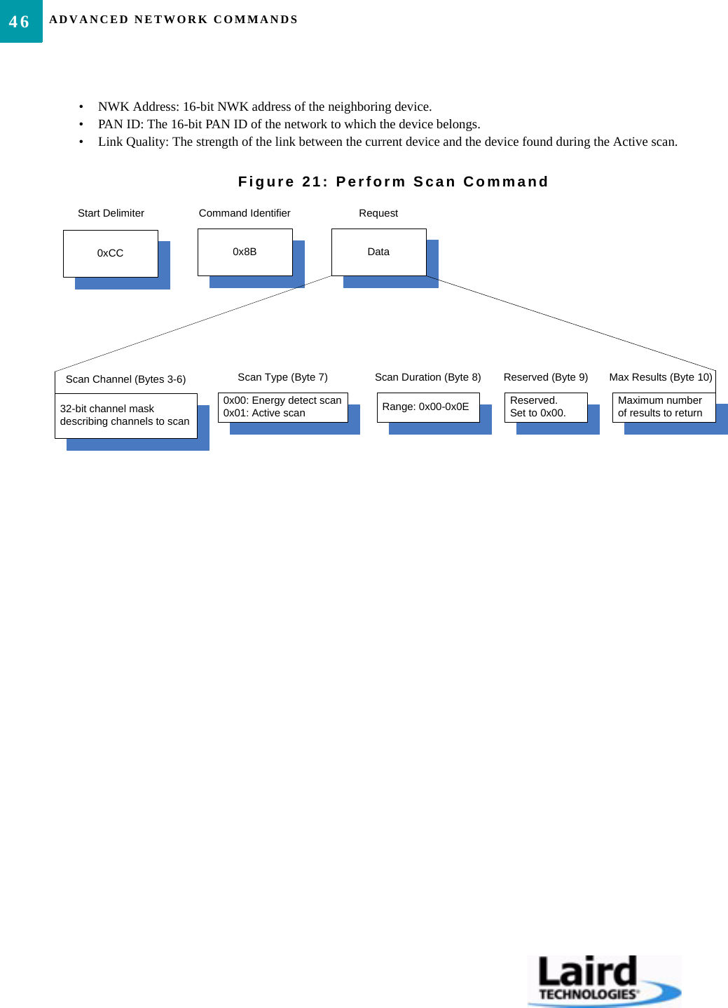
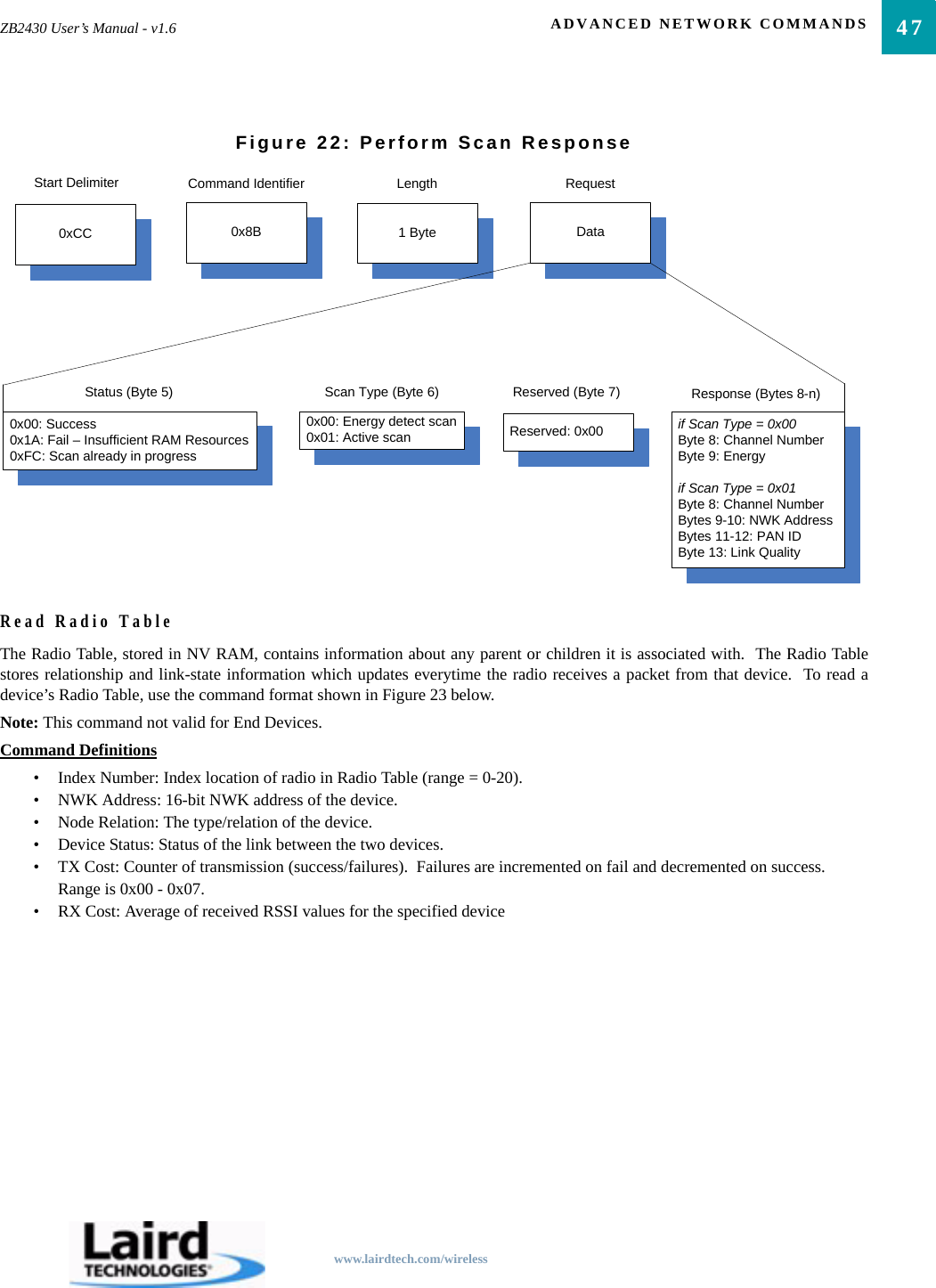
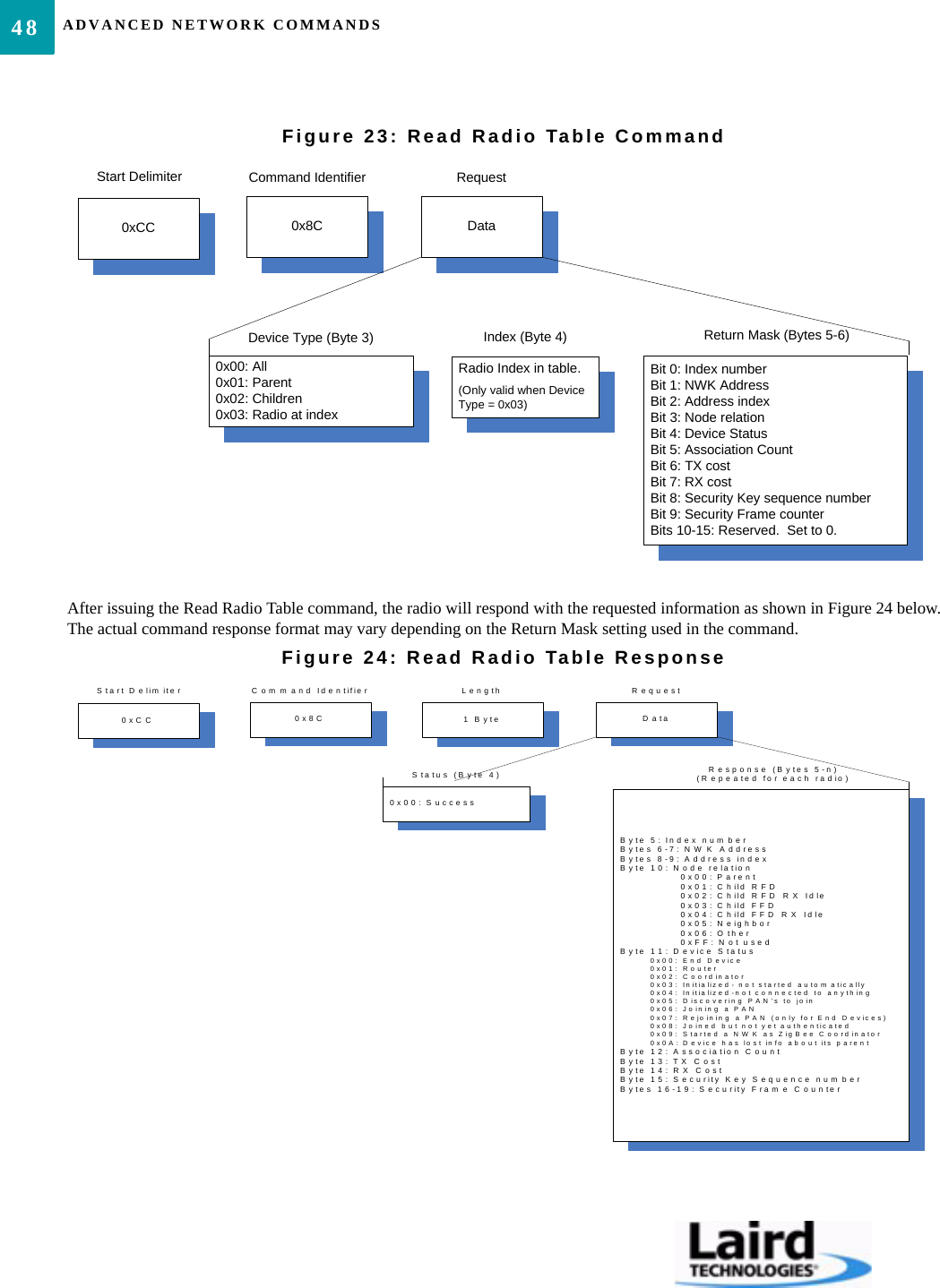
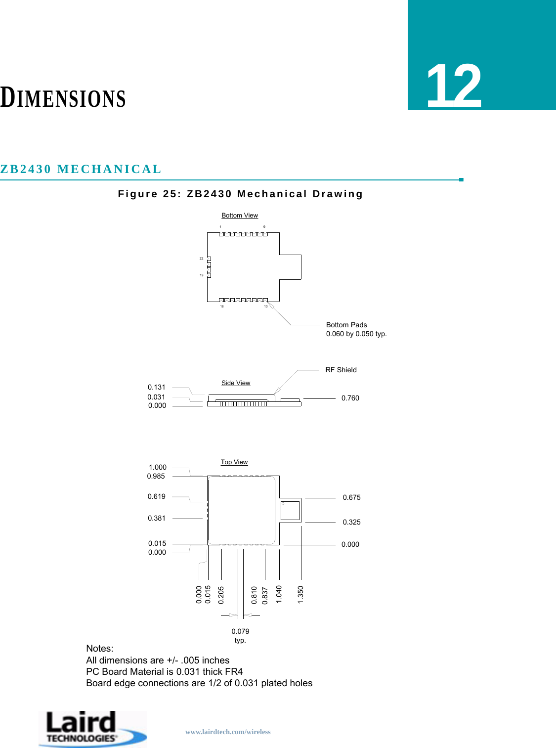
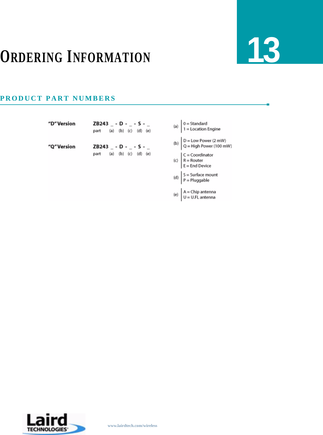
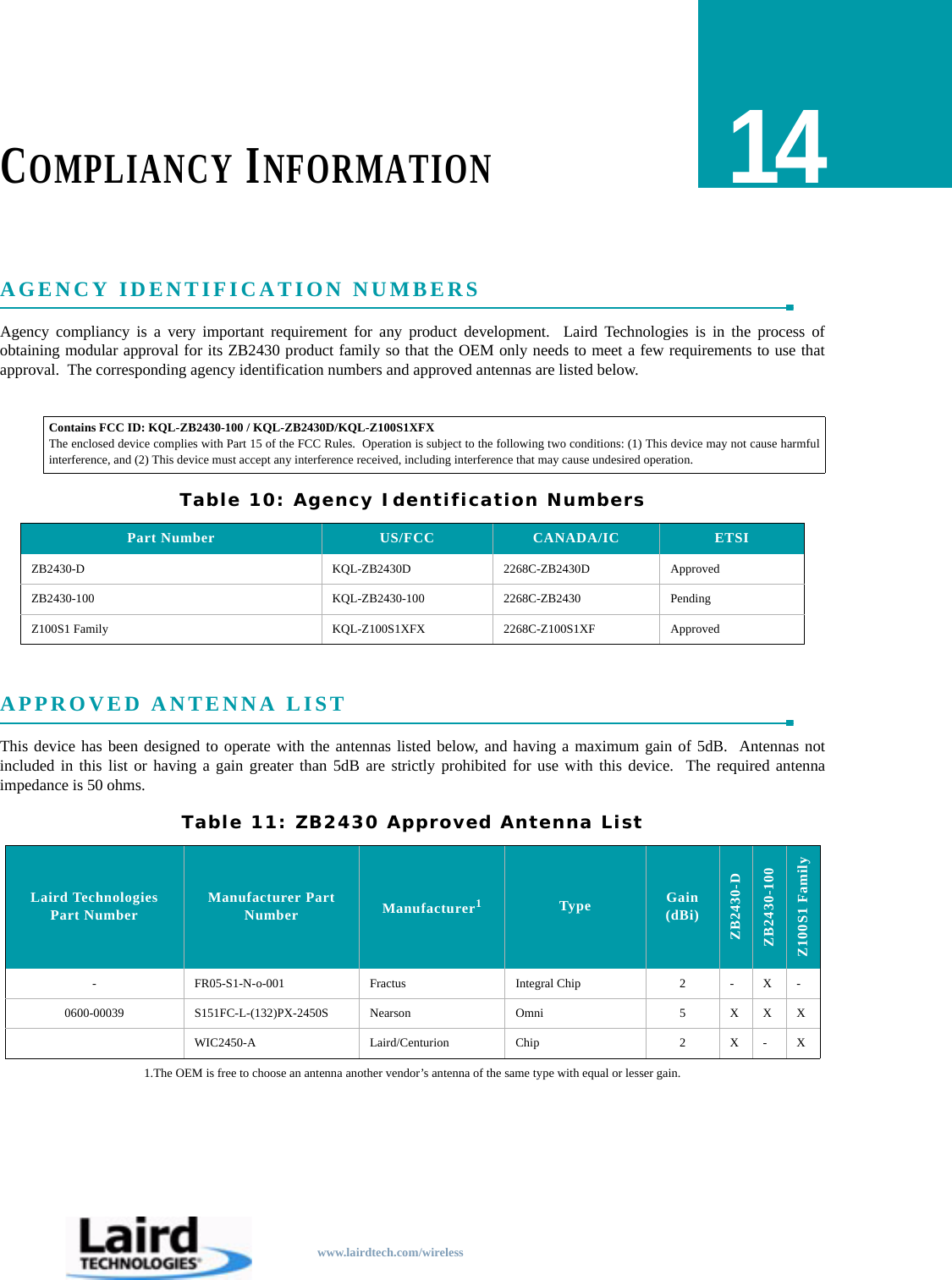
Laird Connectivity Z100S1XFX 2.4 GHz Direct Sequence Spread Spectrum transceiver module User Manual ZB2430 User s Manual 2 0
AeroComm Corporation 2.4 GHz Direct Sequence Spread Spectrum transceiver module ZB2430 User s Manual 2 0

Contents

User Manual
Technical Support: Phone: 800.492.2320E-mail: wireless.support@lairdtech.comWeb: wwwlairdtech.com/wirelessSales: Phone: 800.492.2320E-mail: wirelessinfo@lairdtech.comWeb: www.lairdtech.com/wireless
Document InformationCopyright © 2008 Laird Technologies, Inc. All rights reserved.The information contained in this manual and the accompanying software programs are copyrighted and all rights are reserved byLaird Technologies, Inc. Laird Technologies, Inc. reserves the right to make periodic modifications of this product withoutobligation to notify any person or entity of such revision.  Copying, duplicating, selling, or otherwise distributing any part of thisproduct or accompanying documentation/software without the prior consent of an authorized representative of Laird Technologies,Inc. is strictly prohibited.All brands and product names in this publication are registered trademarks or trademarks of their respective holders.This material is preliminaryInformation furnished by Laird Technologies in this specification is believed to be accurate.  Devices sold by Laird Technologiesare covered by the warranty and patent indemnification provisions appearing in its Terms of Sale only.  Laird Technologies makesno warranty, express, statutory, and implied or by description, regarding the information set forth herein.  Laird Technologiesreserves the right to change specifications at any time and without notice.Laird Technologies’s products are intended for use in normal commercial and industrial applications.  Applications requiringunusual environmental requirements such as military, medical life-support or life-sustaining equipment are specifically notrecommended without additional testing for such application.Limited Warranty, Disclaimer, Limitation of LiabilityFor a period of one (1) year from the date of purchase by the OEM customer, Laird Technologies warrants the OEM transceiveragainst defects in materials and workmanship.  Laird Technologies will not honor this warranty (and this warranty will beautomatically void) if there has been any (1) tampering, signs of tampering; 2) repair or attempt to repair by anyone other than anLaird Technologies authorized technician.This warranty does not cover and Laird Technologies will not be liable for, any damage or failure caused by misuse, abuse, acts ofGod, accidents, electrical irregularity, or other causes beyond Laird Technologies’s control, or claim by other than the originalpurchaser.In no event shall Laird Technologies be responsible or liable for any damages arising:  From the use of product; From the loss ofuse, revenue or profit of the product; or As a result of any event, circumstance, action, or abuse beyond the control of LairdTechnologies, whether such damages be direct, indirect, consequential, special or otherwise and whether such damages areincurred by the person to whom this warranty extends or third party.If, after inspection, Laird Technologies determines that there is a defect, Laird Technologies will repair or replace the OEMtransceiver at their discretion.  If the product is replaced, it may be a new or refurbished product.
Revision HistoryRevision DescriptionVersion 1.0 7/21/06 - Initial Release VersionVersion 1.1 7/25/06 - Updated Pin definitions, corrected status request command todisplay 0x00 as firmware version, updated CC 08, CC 21 and EEPROMbyte write commands.  Corrected PAN ID EEPROM address to address0x78.  Updated Future Enhancements section.Version 1.2 9/15/06 - Changed Reset to active Low.  Changed pin 20 to Sleep pinand is active Low.  Added second mechanical drawing.Version 1.3 1/18/07 - Corrected Read Temperature command.Version 1.4 7/6/07 - Internal Release.Version 1.5 7/17/07 - Added pinout for pluggable module.Version 1.6 8/24/07 - Added API command set.  Added Neighbor, Route, & RadioTable commands.  Added Energy scan command.  Added NV with softreset command.  Added static network parameters information.Updated Broadcast section.  Updated Serial Interface section.  UpdatedChannel Mask section.  Added power-down modes.  Corrected statusrequest response.  Added MAC retries to EEPROM parameter list.Version 1.7 Corrected Read Channel Command (was CC 02 00; changed to CC 02)Version 1.8 12/17/07 - Updated Compliancy Information.  Added approval forZB2430-D.  Updated Approved Antenna List.Version 1.9 1/4/08 - Added new EEPROM parameters for firmware version 1.6 -End Device poll rate, Parent Hold Message, End Device Wake Time,End Device Wake Poll rate, Stop Bit Delay, Modify Wake upon RX,Reload Sleep, NV Restore enable/disable, & RS485 DE/RE.Version 2.0 3/1/08- Updated ZB2430 Features, Updated Current Draw for HighPower module, Updated RF Packet Size in RX Data Buffer and CTS,Updated Read Digital Input, Updated Read ADC, Updated WriteDigital Output, Removed Discover 16-bit NWK Address command,Added Read Voltage cmd, Added Restore Default cmd, Added End-to-End Retries to EEPROM Parameters Table, Updated CTS On/OffThresholds, Updated Read Neighbor Table CommandVersion 2.1 10/28/08-  Updated Laird Brand.  Updated Compliancy informationVersion 2.1.1 12/4/08- Updated FCC guidelines12/9/08- Updated FCC/IC statement
ContentsZB2430 TRANSCEIVER MODULE 1ZB2430 Features 1Overview 1SPECIFICATIONS 2Pin Definitions 4HARDWARE INTERFACE 6Pin Definitions 6Generic I/O 6RXD and TXD 6Test/Sleep Int. 6UP_Reset 6Command/Data 6In Range 6RTS Handshaking* 6CTS Handshaking 7Sleep Ind. 7AD In 7TERMS & DEFINITIONS 8THEORY OF OPERATION 11IEEE 802.15.4 & ZigBee Overview 11Creating a Network 12Mesh 12Parent/Child Relationship 13Network Limitations 14Maximum Network Depth 14Maximum Number of Children per Parent 15ZigBee Addressing 1516-bit Network Address 1564-bit MAC address 16Mesh Routing (AODV) 16Coordinator Addressing 18Broadcast Transmissions 18SERIAL INTERFACE 20Interface Modes 20Transparent Mode 20API Mode 20Serial Interface Baud Rate 21Interface Timeout / RF Packet Size 22Flow Control 22RXD Data Buffer and CTS 23TXD Data Buffer and RTS 23Networking 24Power Down Modes 26Cyclic Sleep 26Deep Sleep 26CONFIGURING THE ZB2430 28AT Commands 29On-the-Fly Control Commands 29Command Descriptions 31EEPROM PARAMETERS 37API OPERATION 41API Transmit Packet 41API Send Data Complete 41API Receive Packet 42ZB2430 ADDRESSING 43ADVANCED NETWORK COMMANDS 45Read Neighbor Table 45Read Route Table 47Perform Scan 49Read Radio Table 51DIMENSIONS 53ZB2430 Mechanical 53ORDERING INFORMATION 54Product Part Numbers 54COMPLIANCY INFORMATION 55Agency Identification Numbers 55Approved antenna List 55FCC / IC Requirements for Modular Approval 55OEM Equipment Labeling Requirements 56Antenna Requirements 56Warnings required in OEM Manuals 56Channel Warning 56
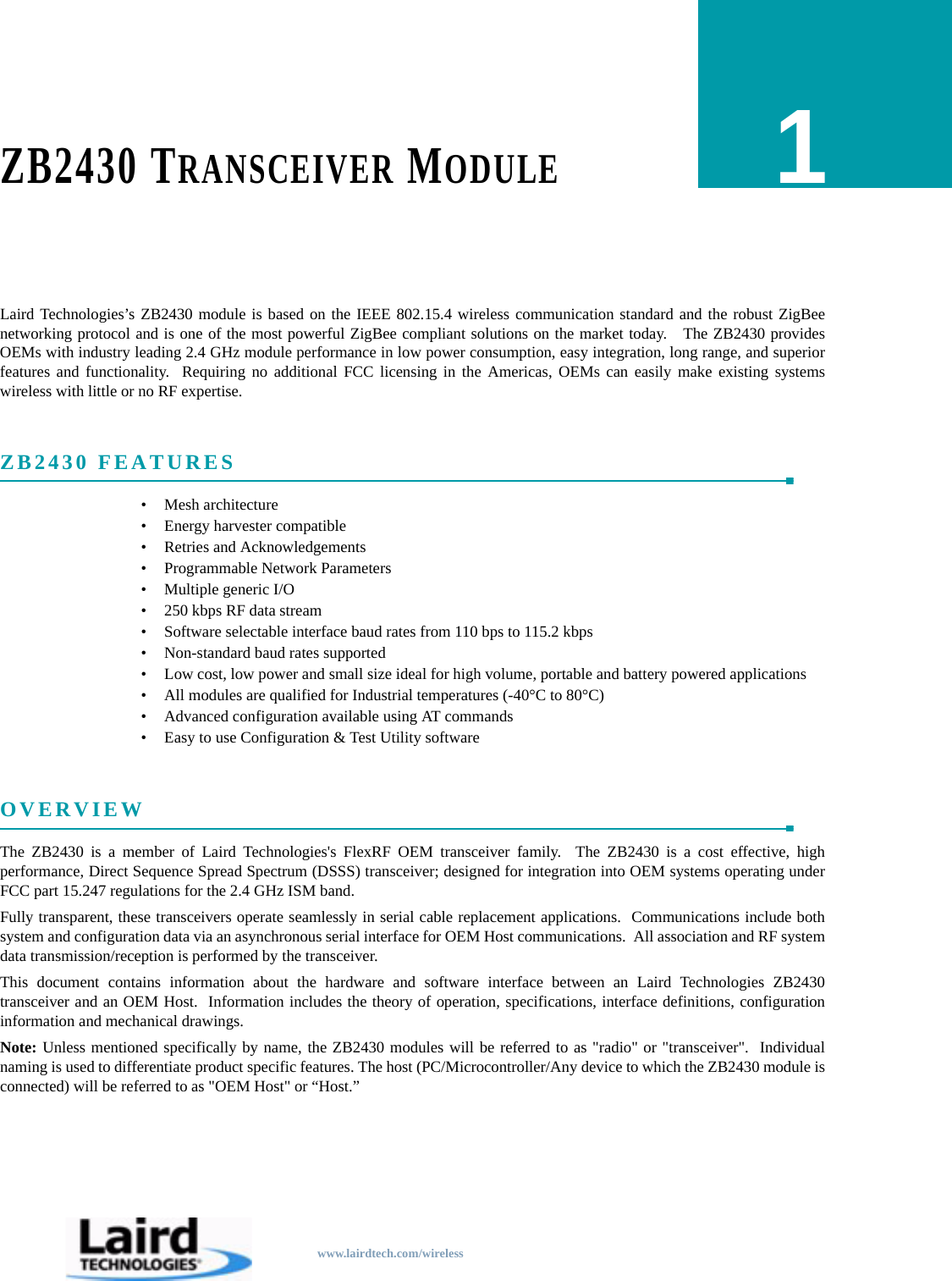
www.lairdtech.com/wirelessZB2430 TRANSCEIVER MODULE1Laird Technologies’s ZB2430 module is based on the IEEE 802.15.4 wireless communication standard and the robust ZigBeenetworking protocol and is one of the most powerful ZigBee compliant solutions on the market today.   The ZB2430 providesOEMs with industry leading 2.4 GHz module performance in low power consumption, easy integration, long range, and superiorfeatures and functionality.  Requiring no additional FCC licensing in the Americas, OEMs can easily make existing systemswireless with little or no RF expertise.ZB2430 FEATURES• Mesh architecture• Energy harvester compatible• Retries and Acknowledgements• Programmable Network Parameters• Multiple generic I/O• 250 kbps RF data stream• Software selectable interface baud rates from 110 bps to 115.2 kbps• Non-standard baud rates supported• Low cost, low power and small size ideal for high volume, portable and battery powered applications• All modules are qualified for Industrial temperatures (-40°C to 80°C)• Advanced configuration available using AT commands• Easy to use Configuration & Test Utility softwareOVERVIEWThe ZB2430 is a member of Laird Technologies's FlexRF OEM transceiver family.  The ZB2430 is a cost effective, highperformance, Direct Sequence Spread Spectrum (DSSS) transceiver; designed for integration into OEM systems operating underFCC part 15.247 regulations for the 2.4 GHz ISM band.Fully transparent, these transceivers operate seamlessly in serial cable replacement applications.  Communications include bothsystem and configuration data via an asynchronous serial interface for OEM Host communications.  All association and RF systemdata transmission/reception is performed by the transceiver.This document contains information about the hardware and software interface between an Laird Technologies ZB2430transceiver and an OEM Host.  Information includes the theory of operation, specifications, interface definitions, configurationinformation and mechanical drawings. Note: Unless mentioned specifically by name, the ZB2430 modules will be referred to as "radio" or "transceiver".  Individualnaming is used to differentiate product specific features. The host (PC/Microcontroller/Any device to which the ZB2430 module isconnected) will be referred to as "OEM Host" or “Host.”
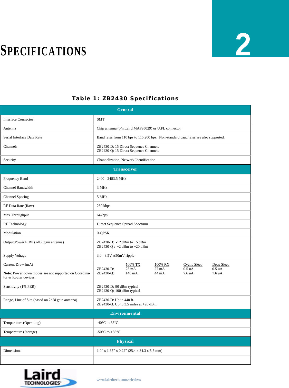
www.lairdtech.com/wirelessSPECIFICATIONS2Table 1: ZB2430 SpecificationsGeneralInterface Connector SMTAntenna Chip antenna (p/n Laird MAF95029) or U.FL connectorSerial Interface Data Rate Baud rates from 110 bps to 115,200 bps.  Non-standard baud rates are also supported.Channels ZB2430-D: 15 Direct Sequence ChannelsZB2430-Q: 15 Direct Sequence ChannelsSecurity Channelization, Network IdentificationTransceiverFrequency Band 2400 - 2483.5 MHzChannel Bandwidth 3 MHzChannel Spacing 5 MHzRF Data Rate (Raw) 250 kbpsMax Throughput 64kbpsRF Technology Direct Sequence Spread SpectrumModulation 0-QPSKOutput Power EIRP (2dBi gain antenna) ZB2430-D:  -12 dBm to +5 dBmZB2430-Q :  +2 dBm to +20 dBmSupply Voltage 3.0 - 3.5V, ±50mV rippleCurrent Draw (mA)Note: Power down modes are not supported on Coordina-tor & Router devices.100% TX 100% RX Cyclic Sleep Deep SleepZB2430-D: 25 mA 27 mA 0.5 uA 0.5 uAZB2430-Q: 140 mA 44 mA 7.6 uA 7.6 uASensitivity (1% PER) ZB2430-D:-90 dBm typicalZB2430-Q:-100 dBm typicalRange, Line of Site (based on 2dBi gain antenna) ZB2430-D: Up to 440 ft.ZB2430-Q: Up to 3.5 miles at +20 dBmEnvironmentalTemperature (Operating) -40°C to 85°CTemperature (Storage) -50°C to +85°CPhysicalDimensions 1.0” x 1.35” x 0.22” (25.4 x 34.3 x 5.5 mm)
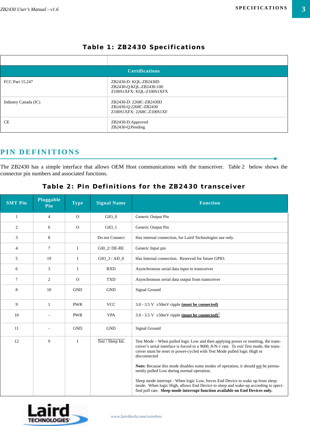
3ZB2430 User’s Manual - v1.6 SPECIFICATIONSwww.lairdtech.com/wirelessPIN DEFINITIONSThe ZB2430 has a simple interface that allows OEM Host communications with the transceiver.  Table 2  below shows theconnector pin numbers and associated functions.CertificationsFCC Part 15.247 ZB2430-D: KQL-ZB2430DZB2430-Q:KQL-ZB2430-100Z100S1XFX: KQL-Z100S1XFXIndustry Canada (IC) ZB2430-D: 2268C-ZB2430DZB2430-Q:2268C-ZB2430Z100S1XFX: 2268C-Z100S1XFCE ZB2430-D:ApprovedZB2430-Q:PendingTable 2: Pin Definitions for the ZB2430 transceiverSMT Pin Pluggable Pin Type Signal Name Function1 4 O GIO_0 Generic Output Pin2 6 O GIO_1 Generic Output Pin3 8 Do not Connect Has internal connection, for Laird Technologies use only.4 7 I GI0_2/ DE-RE Generic Input pin5 19 I GIO_3 / AD_0 Has Internal connection.  Reserved for future GPIO.6 3 I RXD Asynchronous serial data input to transceiver7 2 O TXD Asynchronous serial data output from transceiver8 10 GND GND Signal Ground9 1 PWR VCC 3.0 - 3.5 V  ±50mV ripple (must be connected)10 -PWR VPA 3.0 - 3.5 V  ±50mV ripple (must be connected)111 -GND GND Signal Ground12 9 I Test / Sleep Int. Test Mode – When pulled logic Low and then applying power or resetting, the trans-ceiver’s serial interface is forced to a 9600, 8-N-1 rate.  To exit Test mode, the trans-ceiver must be reset or power-cycled with Test Mode pulled logic High or disconnectedNote: Because this mode disables some modes of operation, it should not be perma-nently pulled Low during normal operation.Sleep mode interrupt - When logic Low, forces End Device to wake up from sleep mode.  When logic High, allows End Device to sleep and wake-up according to speci-fied poll rate.  Sleep mode interrupt function available on End Devices only.Table 1: ZB2430 Specifications
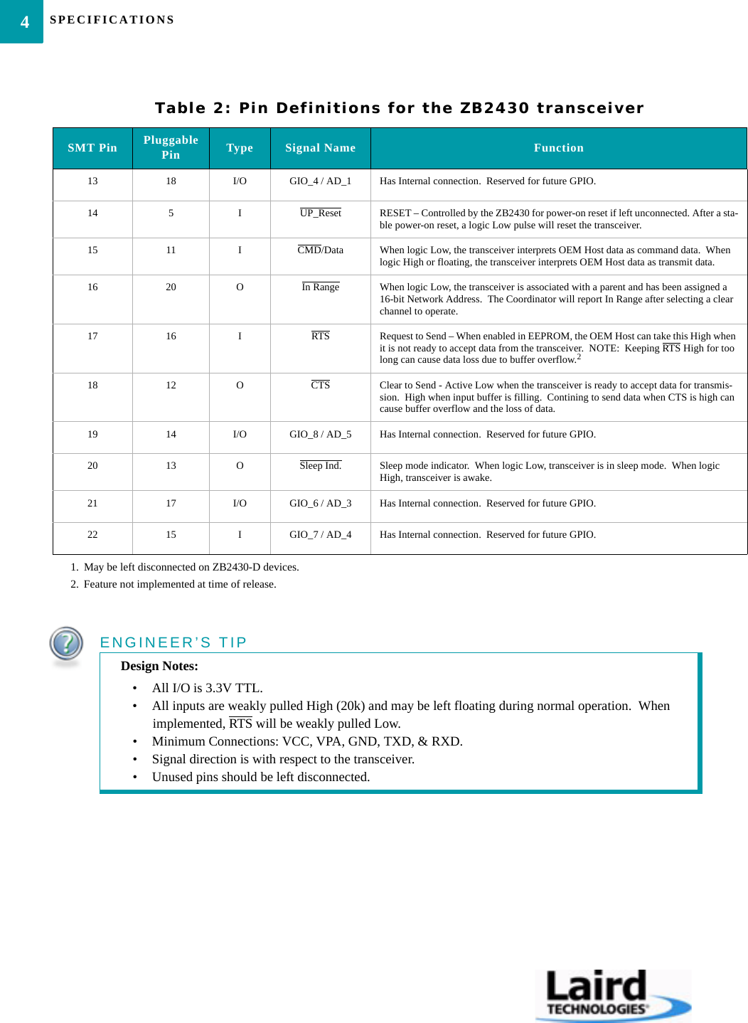
SPECIFICATIONS413 18 I/O GIO_4 / AD_1 Has Internal connection.  Reserved for future GPIO.14 5 I UP_Reset RESET – Controlled by the ZB2430 for power-on reset if left unconnected. After a sta-ble power-on reset, a logic Low pulse will reset the transceiver.15 11 ICMD/Data When logic Low, the transceiver interprets OEM Host data as command data.  When logic High or floating, the transceiver interprets OEM Host data as transmit data.16 20 O In Range When logic Low, the transceiver is associated with a parent and has been assigned a 16-bit Network Address.  The Coordinator will report In Range after selecting a clear channel to operate.17 16 I RTS Request to Send – When enabled in EEPROM, the OEM Host can take this High when it is not ready to accept data from the transceiver.  NOTE:  Keeping RTS High for too long can cause data loss due to buffer overflow.218 12 O CTS Clear to Send - Active Low when the transceiver is ready to accept data for transmis-sion.  High when input buffer is filling.  Contining to send data when CTS is high can cause buffer overflow and the loss of data.19 14 I/O GIO_8 / AD_5 Has Internal connection.  Reserved for future GPIO.20 13 O Sleep Ind. Sleep mode indicator.  When logic Low, transceiver is in sleep mode.  When logic High, transceiver is awake.21 17 I/O GIO_6 / AD_3 Has Internal connection.  Reserved for future GPIO.22 15 I GIO_7 / AD_4 Has Internal connection.  Reserved for future GPIO.1. May be left disconnected on ZB2430-D devices.2. Feature not implemented at time of release.ENGINEER’S TIPDesign Notes:• All I/O is 3.3V TTL.• All inputs are weakly pulled High (20k) and may be left floating during normal operation.  When implemented, RTS will be weakly pulled Low.• Minimum Connections: VCC, VPA, GND, TXD, & RXD.• Signal direction is with respect to the transceiver.• Unused pins should be left disconnected.Table 2: Pin Definitions for the ZB2430 transceiverSMT Pin Pluggable Pin Type Signal Name Function
www.lairdtech.com/wirelessHARDWARE INTERFACE3PIN DEFINITIONS Generic I/OBoth GIn and GOn pins serve as generic input/output pins. Reading and writing of these pins can be performed on-the-fly usingCC Commands.RXD and TXDThe ZB2430 accepts 3.3 VDC TTL level asynchronous serial data from the OEM Host via the RXD pin.  Data is sent from thetransceiver, at 3.3V levels, to the OEM Host via the TXD pin. Test/Sleep Int.Test Mode - When pulled logic Low before applying power or resetting, the transceiver's serial interface is forced to 9600, 8-N-1(8 data bits, No parity, 1 stop bit): regardless of actual EEPROM setting.  The interface timeout is also set to 3 ms and the RFpacket size is set to the default size of 0x54 (84 bytes).  To exit, the transceiver must be reset or power-cycled with Test pin logicHigh or disconnected.Note: Because this pin disables some modes of operation, it should not be permanently pulled Low during normal operation.Sleep Mode Interrupt - When logic Low, forces End Device to wake up from sleep mode.  When logic High, allows End Device  tosleep and wake-up according to specified poll rate.  Sleep Mode interrupt function available on End Devices only. UP_ResetUP_Reset provides a direct connection to the reset pin on the ZB2430 microprocessor and is used to force a soft reset.  For a validreset, reset must be asserted Low for an absolute minimum of 250 ns.Command/DataWhen logic High, the transceiver interprets incoming serial data as transmit data to be sent to other transceivers. When logic Low,the transceiver interprets incoming serial data as command data.  When logic Low, data packets from the radio will not betransmitted over the RF interface however incoming packets from other radios will still be received.In RangeThe In Range pin will be driven low when the radio is associated with a network.  In Range will always be driven low on aCoordinator.RTS Handshaking*With RTS mode disabled, the transceiver will send any received data to the OEM Host as soon as it is received.  However, someOEM Hosts are not able to accept data from the transceiver all of the time. With RTS enabled, the OEM Host can prevent thetransceiver from sending it data by de-asserting RTS (High).  Once RTS is re-asserted (Low), the transceiver will send packets tothe OEM Host as they are received.  Note:  Leaving RTS de-asserted for too long can cause data loss once the transceiver's receive buffer reaches capacity.*Feature not implemented at time of release.
HARDWARE INTERFACE6CTS HandshakingIf the transceiver buffer fills up and more bytes are sent to it before the buffer can be emptied, data loss will occur.  The transceiverprevents this loss by deasserting CTS High as the buffer fills up and asserting CTS Low as the buffer is emptied.  CTS should bemonitored by the Host device and data flow to the radio should be stopped when CTS is High.Sleep Ind.Sleep Indicator output.  Sleep Ind. can be used to determine whether or not the transceiver is sleeping.  When logic Low, thetransceiver is in sleep mode.  When logic High, the transceiver is awake.AD InAD In can be used as a cost savings to replace Analog-to-Digital converter hardware with the onboard 12-bit ADC.  Reading ofthis pin can be performed locally using the Read ADC command found in the On-the-Fly Control Command Reference.
www.lairdtech.com/wirelessTERMS & DEFINITIONS4Ad-Hoc Network:  A wireless network composed of communicating devices without preexisting infrastructure.  Typically createdin a spontaneous manner and is self-organizing and self-maintaining.Association:  The process of joining a ZigBee PAN.  A device joins the Network by joining a Coordinator or Router which haspreviously associated with the Network.  Upon joining, the Parent device issues a 16-bit Network Address to the device.Broadcast:  Broadcast packets are sent to multiple radios.  The ZB2430 allows several different broadcast types includingbroadcast to all devices & broadcast to Coordinator & all Routers.Broadcast jitter:  The random delay which is automatically introduced by a device before relaying a broadcast packet to preventpacket collisions.Channel:  The frequency selected for data communications within the PAN.  The channel is selected by the Network Coordinatoron power-up.Channel Mask:  The Channel Mask is a  32-bit field which specifies the range of allowable channels that the radio has to selectfrom when choosing an RF channel.  Valid only when Channel Select mode is enabled in EEPROM.Clear Channel Assessment:  An evaluation of the communication channel prior to a transmission to determine if the channel iscurrently occupied.Energy Scan:  A sweep of the entire frequency band which reports noise readings on every channel & is also capable of detectingCoordinators and reporting their Channel location.FFD:  Full Function Device.  The Network Coordinator & Routers are examples of FFD’s.IEEE 802.15.4:  IEEE standard for Low-Power Wireless Personal Area Networks (WPAN’s).  Specifies the physical interfacebetween ZigBee devices.MAC Address:  A unique 64-bit address assigned to each radio.  This address cannot be modified and never changes.  It is used bythe network to identify the device when assigning 16-bit Network Addresses.Maximum Network Depth:  The maximum number or Routers (hops) that a device can be away from the Coordinator.  Thecurrent profile limit is 5.Maximum Number of Routers:  The total number of children that can serve as Routers for a Network device.  The current profilelimit is 6.
TERMS & DEFINITIONS8Maximum Number of Children:  The total number of children that can be associated with a single Network device.  The currentprofile limit is 20; comprising of up to 6 Routers and 14 End Devices.Mesh Network:   An interconnection of nodes where nodes are permitted to transmit data directly to any other node.Neighbor Table:   A table used by the Coordinator and Router(s) to keep track of other devices operating in the same coveragearea.Network Address:  The unique 16-bit address assigned to a device upon joining a PAN.  This address is used for routing messagesbetween devices and can be different each time a device is powered on.  The Network Coordinator will always have a NetworkAddress of 0x0000.  Note that addresses are not assigned in numerical order.Operating Channel:  The specific frequency selected for data communications.  The operating channel is determined by theCoordinator on power-up.Orphan Device:  A device which has lost communication contact with or information about its Parent device.PAN:  Personal Area Network.  Includes a Network Coordinator and one or more Routers/End Devices.  The Network formation isdetermined by the Maximum Network Depth, Maximum Number of Routers, and Maximum Number of Children.PAN ID:  Similar to a Network ID.  Devices which are operating with different PAN ID’s will not be associated to the samenetwork.Parent/Child:  When a device joins the Network, it becomes a child of the device with which it is associated.  Similarly, thedevice with which it associated becomes its parent device.  Network devices can have multiple children, but only one parent.  EndDevices cannot be parents and are always children of the Coordinator or a Router.  The Coordinator does not have a parent device.POS: Personal Operating Space.  The area within reception range of a specific device.Profile:  A collection of device descriptions, which together form a coorperative application.  Devices utilizing different profileswill only support very basic inter-communications.  The ZB2430 uses a private profile as specified by Laird Technologies.RFD:  Reduced Function Device.  The End Device is an example of an RFD.Route Discovery:  An operation using RREQ and RREP’s in which a ZigBee Coordinator or Router discovers a route to a deviceoutside its POS.Route Reply (RREP):  A ZigBee command used to reply to a Route Request command.Route Request (RREQ):  A ZigBee command used to discover paths through the network over which messages may be relayed.
9ZB2430 User’s Manual - v1.6 TERMS & DEFINITIONSwww.lairdtech.com/wirelessRouting Table:  A table in which the Coordinator or Router(s) store information required to participate in the routing of datapackets throughout the network.  The entire route is not stored, only the first step in the route.Star Network:  A network employing a single, central device through which all communication between devices must pass.TX Cost:  A counter of transmission successes/failures.  TX Cost starts at 0x00, increments by one every time a packet fails to bedelivered, and decrements by one every time a packet is successfully delivered.  TX Cost has a range between 0x00 and 0x04.Unicast:  Unicast packets contain a destination address and are received by a single radio only.  Unicast packets are point-to-pointand do not include Broadcast packets.ZigBee Stack:  A Network specification based on the IEEE 802.15.4 Standard for Wireless Personal Area Networks (WPANs).The ZB2430 uses the Z-Stack (designed by TI) v.1.4.2 and complies to the ZigBee 2006 specification.ZigBee Alliance:  An association of companies working together to create a low-cost, low power consumption, two-way wirelesscommunications standard (http://www.zigbee.org).
www.lairdtech.com/wirelessTHEORY OF OPERATION5IEEE 802.15.4 & ZIGBEE OVERVIEWThe ZB2430 uses the ZigBee protocol stack, a network layer protocol which uses small, low power digital transceivers based onthe IEEE 802.15.4 hardware standard. The 802.15.4 standard is a specification for a cost-effective, low data rate (<250 kbps), 2.4GHz or 868/928 MHz wireless technology designed for personal-area and device-to-device wireless networking.The IEEE 802.15.4 standard specifies the hardware requirements, including frequency bands, receiver sensitivity, modulation andspreading requirements.  The ZigBee layer is the software layer that sits atop the 802.15.4 PHY/MAC layer and performs allpacket routing and mesh networking.There are three device types present in a ZigBee network: Coordinator (Full Function Device), Router (Full Function Device), andEnd Device (Reduced Function Device).  Each network consists of a single Coordinator, optional Router(s), and optional ReducedFunction End Device(s).CoordinatorThe Coordinator is responsible for establishing the operatingchannel and PAN ID for the entire Network.  Once theCoordinator has established a Network, it allows Routers andEnd Devices to join the Network; assigning each device a unique16-bit Network Address.The Coordinator is intended to be mains powered (always on).•  One Coordinator per Network•  Establishes Channel and PAN ID•  Responsible for Network formation and   maintenance•  Full Function Device•  Packet routing capabilities•  Mains powered (always on)•  Power down modes are not supported•  Network address of 0x0000RouterRouters are responsible for creating and maintaining Networkinformation and determining the optimal route for a data packet.Routers must first associate with the Network before otherdevices can join through them.Routers are intended to be mains powered (always on).•  Multiple Routers can be used•  Allows other Routers/End Devices to join the Network•  Full Function Device•  Packet routing capabilities•  Mains powered (always on)•  Power down modes are not supported•  Unique netowork address dynamically assigned by parent
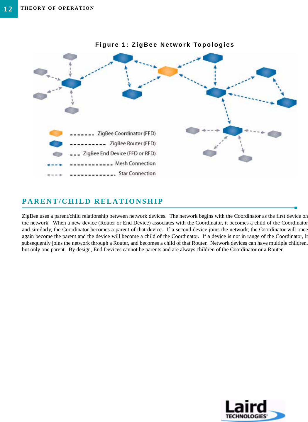
11ZB2430 User’s Manual - v1.6 THEORY OF OPERATIONwww.lairdtech.com/wirelessCREATING A NETWORKThe IEEE 802.15.4 MAC provides support for two wireless network topologies: star and mesh.  The management of thesenetworks is performed by the ZigBee layer.  All devices, regardless of topology, participate in the network using their unique 16-bit address assigned by the Coordinator.MeshThe mesh topology allows any Full Function Device (Coordinator or Router) to communicate directly with any other device withinits range and to have messages relayed to devices which are out of range via multi-hop routing of messages.  While a FFD devicecan communicate with a Reduced Function Device (RFD), RFD’s cannot directly route messages and must have their messagesrouted by their parent device (Coordinator or Router).  ZigBee mesh enables the formation of more complex networks, includingad-hoc, self-organizing, and self-healing structures.Figure 1  shows a typical ZigBee network architecture.End DeviceWhile Coordinators and Routers can communicate with anydevice type, End Devices can communicate only through theirparent device.  Ideally the End Devices will be in sleep mode allthe time.  When they have data to send, they wake up, send thedata and then go back to sleep.  The Parent (Coordinator/Router)of an End Device should be mains powered  to allow it to storedata to be sent to the sleeping End Device.•  Multiple End Devices can be used•  No packet routing capabilities•  Can communicate with other devices in the Network through its Parent Device•  Reduced Function Device•  Mains or battery powered•  Power down modes are supported•  Unique network address dynamically asssigned by parent
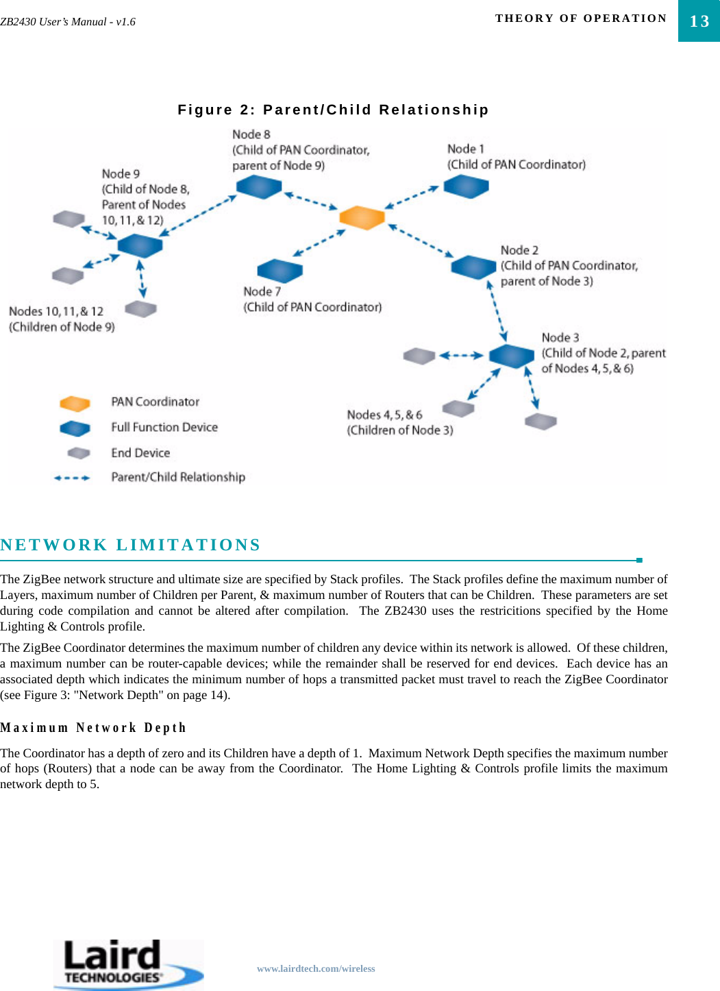
THEORY OF OPERATION12Figure 1: ZigBee Network TopologiesPARENT/CHILD RELATIONSHIPZigBee uses a parent/child relationship between network devices.  The network begins with the Coordinator as the first device onthe network.  When a new device (Router or End Device) associates with the Coordinator, it becomes a child of the Coordinatorand similarly, the Coordinator becomes a parent of that device.  If a second device joins the network, the Coordinator will onceagain become the parent and the device will become a child of the Coordinator.  If a device is not in range of the Coordinator, itsubsequently joins the network through a Router, and becomes a child of that Router.  Network devices can have multiple children,but only one parent.  By design, End Devices cannot be parents and are always children of the Coordinator or a Router.
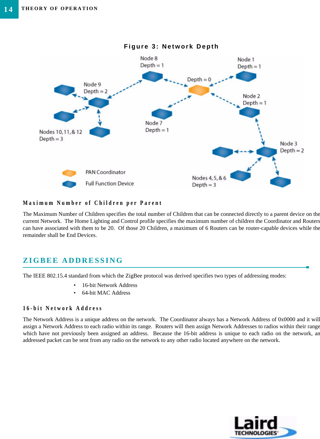
13ZB2430 User’s Manual - v1.6 THEORY OF OPERATIONwww.lairdtech.com/wirelessFigure 2: Parent/Child RelationshipNETWORK LIMITATIONSThe ZigBee network structure and ultimate size are specified by Stack profiles.  The Stack profiles define the maximum number ofLayers, maximum number of Children per Parent, & maximum number of Routers that can be Children.  These parameters are setduring code compilation and cannot be altered after compilation.  The ZB2430 uses the restricitions specified by the HomeLighting & Controls profile.The ZigBee Coordinator determines the maximum number of children any device within its network is allowed.  Of these children,a maximum number can be router-capable devices; while the remainder shall be reserved for end devices.  Each device has anassociated depth which indicates the minimum number of hops a transmitted packet must travel to reach the ZigBee Coordinator(see Figure 3: "Network Depth" on page 14).Maximum Network DepthThe Coordinator has a depth of zero and its Children have a depth of 1.  Maximum Network Depth specifies the maximum numberof hops (Routers) that a node can be away from the Coordinator.  The Home Lighting & Controls profile limits the maximumnetwork depth to 5.
THEORY OF OPERATION14Figure 3: Network DepthMaximum Number of Children per ParentThe Maximum Number of Children specifies the total number of Children that can be connected directly to a parent device on thecurrent Network.  The Home Lighting and Control profile specifies the maximum number of children the Coordinator and Routerscan have associated with them to be 20.  Of those 20 Children, a maximum of 6 Routers can be router-capable devices while theremainder shall be End Devices.ZIGBEE ADDRESSINGThe IEEE 802.15.4 standard from which the ZigBee protocol was derived specifies two types of addressing modes:• 16-bit Network Address• 64-bit MAC Address16-bit Network AddressThe Network Address is a unique address on the network.  The Coordinator always has a Network Address of 0x0000 and it willassign a Network Address to each radio within its range.  Routers will then assign Network Addresses to radios within their rangewhich have not previously been assigned an address.  Because the 16-bit address is unique to each radio on the network, anaddressed packet can be sent from any radio on the network to any other radio located anywhere on the network.
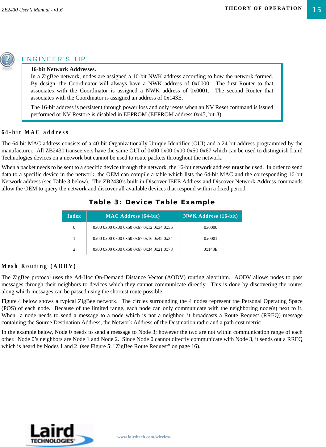
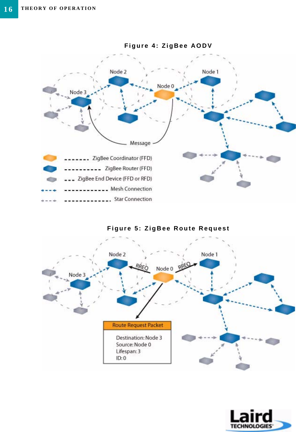
15ZB2430 User’s Manual - v1.6 THEORY OF OPERATIONwww.lairdtech.com/wireless64-bit MAC addressThe 64-bit MAC address consists of a 40-bit Organizationally Unique Identifier (OUI) and a 24-bit address programmed by themanufacturer.  All ZB2430 transceivers have the same OUI of 0x00 0x00 0x00 0x50 0x67 which can be used to distinguish LairdTechnologies devices on a network but cannot be used to route packets throughout the network.When a packet needs to be sent to a specific device through the network, the 16-bit network address must be used.  In order to senddata to a specific device in the network, the OEM can compile a table which lists the 64-bit MAC and the corresponding 16-bitNetwork address (see Table 3 below).  The ZB2430’s built-in Discover IEEE Address and Discover Network Address commandsallow the OEM to query the network and discover all available devices that respond within a fixed period.Mesh Routing (AODV)The ZigBee protocol uses the Ad-Hoc On-Demand Distance Vector (AODV) routing algorithm.  AODV allows nodes to passmessages through their neighbors to devices which they cannot communicate directly.  This is done by discovering the routesalong which messages can be passed using the shortest route possible.Figure 4 below shows a typical ZigBee network.  The circles surrounding the 4 nodes represent the Personal Operating Space(POS) of each node.  Because of the limited range, each node can only communicate with the neighboring node(s) next to it.When  a node needs to send a message to a node which is not a neighbor, it broadcasts a Route Request (RREQ) messagecontaining the Source Destination Address, the Network Address of the Destination radio and a path cost metric.In the example below, Node 0 needs to send a message to Node 3; however the two are not within communication range of eachother.  Node 0’s neighbors are Node 1 and Node 2.  Since Node 0 cannot directly communicate with Node 3, it sends out a RREQwhich is heard by Nodes 1 and 2  (see Figure 5: "ZigBee Route Request" on page 16).ENGINEER’S TIP16-bit Network Addresses.In a ZigBee network, nodes are assigned a 16-bit NWK address according to how the network formed.By design, the Coordinator will always have a NWK address of 0x0000.  The first Router to thatassociates with the Coordinator is assigned a NWK address of 0x0001.  The second Router thatassociates with the Coordinator is assigned an address of 0x143E.The 16-bit address is persistent through power loss and only resets when an NV Reset command is issuedperformed or NV Restore is disabled in EEPROM (EEPROM address 0x45, bit-3).Table 3: Device Table ExampleIndex MAC Address (64-bit) NWK Address (16-bit)0 0x00 0x00 0x00 0x50 0x67 0x12 0x34 0x56 0x00001 0x00 0x00 0x00 0x50 0x67 0x16 0x45 0x34 0x00012 0x00 0x00 0x00 0x50 0x67 0x34 0x21 0x78 0x143E
THEORY OF OPERATION16Figure 4: ZigBee AODVFigure 5: ZigBee Route Request
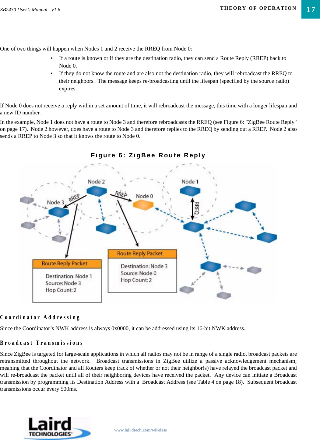
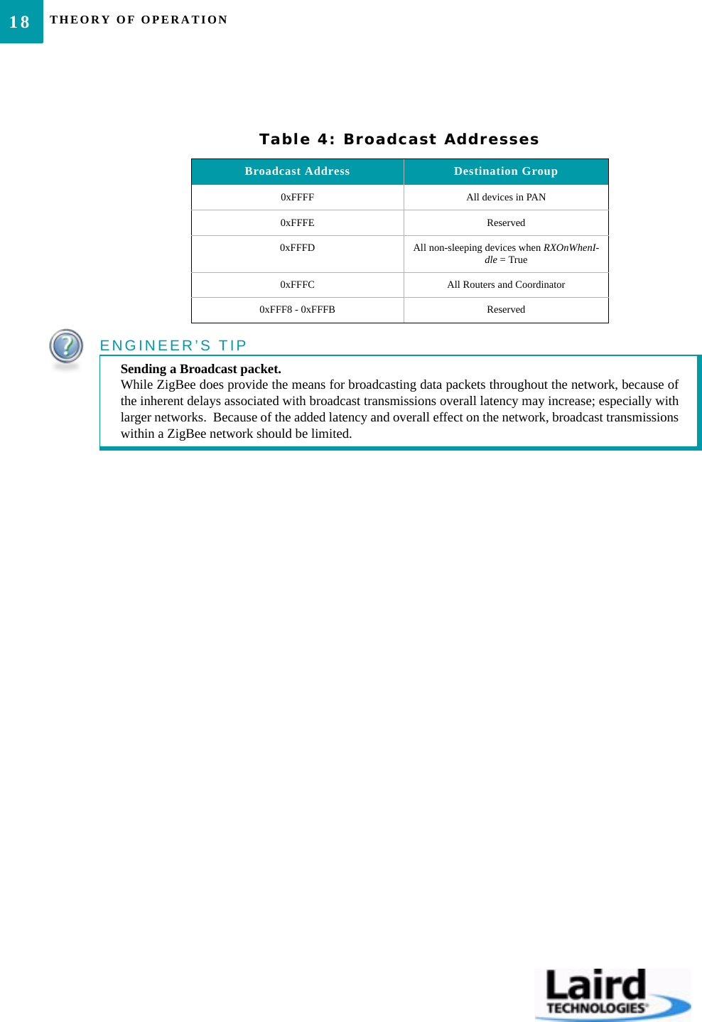
17ZB2430 User’s Manual - v1.6 THEORY OF OPERATIONwww.lairdtech.com/wirelessOne of two things will happen when Nodes 1 and 2 receive the RREQ from Node 0:• If a route is known or if they are the destination radio, they can send a Route Reply (RREP) back to Node 0.• If they do not know the route and are also not the destination radio, they will rebroadcast the RREQ to their neighbors.  The message keeps re-broadcasting until the lifespan (specified by the source radio) expires.If Node 0 does not receive a reply within a set amount of time, it will rebroadcast the message, this time with a longer lifespan anda new ID number.In the example, Node 1 does not have a route to Node 3 and therefore rebroadcasts the RREQ (see Figure 6: "ZigBee Route Reply"on page 17).  Node 2 however, does have a route to Node 3 and therefore replies to the RREQ by sending out a RREP.  Node 2 alsosends a RREP to Node 3 so that it knows the route to Node 0.Figure 6: ZigBee Route ReplyCoordinator AddressingSince the Coordinator’s NWK address is always 0x0000, it can be addressed using its 16-bit NWK address.Broadcast TransmissionsSince ZigBee is targeted for large-scale applications in which all radios may not be in range of a single radio, broadcast packets areretransmitted throughout the network.  Broadcast transmissions in ZigBee utilize a passive acknowledgement mechanism;meaning that the Coordinator and all Routers keep track of whether or not their neighbor(s) have relayed the broadcast packet andwill re-broadcast the packet until all of their neighboring devices have received the packet.  Any device can initiate a Broadcasttransmission by programming its Destination Address with a  Broadcast Address (see Table 4 on page 18).  Subsequent broadcasttransmissions occur every 500ms.
THEORY OF OPERATION18Table 4: Broadcast AddressesBroadcast Address Destination Group0xFFFF All devices in PAN0xFFFE Reserved0xFFFD All non-sleeping devices when RXOnWhenI-dle = True0xFFFC All Routers and Coordinator0xFFF8 - 0xFFFB ReservedENGINEER’S TIPSending a Broadcast packet.While ZigBee does provide the means for broadcasting data packets throughout the network, because ofthe inherent delays associated with broadcast transmissions overall latency may increase; especially withlarger networks.  Because of the added latency and overall effect on the network, broadcast transmissionswithin a ZigBee network should be limited.
www.lairdtech.com/wirelessSERIAL INTERFACE6The ZB2430 transceiver module interfaces to the OEM Host via an asynchronous 3.3V serial UART interface; allowing themodule to be easily integrated into any 3.3V system without requiring any level translation.  The module can communicate withany logic and voltage compatible UART; or to any serial device with an additional level translator.INTERFACE MODESThe ZB2430 has two different types of interface modes:• Transparent Mode• API ModeTransparent ModeWhen operating in Transparent Mode, the ZB2430 can act as a direct serial cable replacement in which received RF data isforwarded over the serial interface and vice versa.  Additionally, many parameters can be configured using either AT commands orby toggling the Command/Data pin on the transceiver.  In transparent mode, the radio needs to be programmed with the NetworkAddress of the desired recipient.  The destination address can be programmed permanently or on-the-fly.When Transparent Mode is used, data is stored in the TX buffer until one of the following occurs:• The RF packet size is reached (EEPROM address 0x5A)• An Interface Timeout occurs (EEPROM address 0x58)API ModeAPI Mode is an alternative to the default Transparent operation of the ZB2430 and provides dynamic packet routing and packetaccounting abilities to the OEM Host without requiring extensive programming by the OEM Host.  API Mode utilizes specificframe-based packet formats; specifying various vital parameters used to control radio settings and packet routing on a packet-by-packet basis.  The API features can be used in any combination that suits the OEM’s application specific needs.API Mode provides an alternative method of configuring modules and message routing at the OEM Host level; without requiringthe use of Command Mode.  The ZB2430 has three API functions:• Transmit API• Receive API• API Send Data CompleteFor additional details and examples, please refer to the API section on page  39.
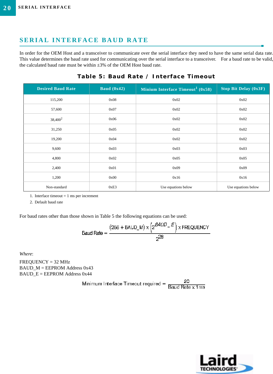
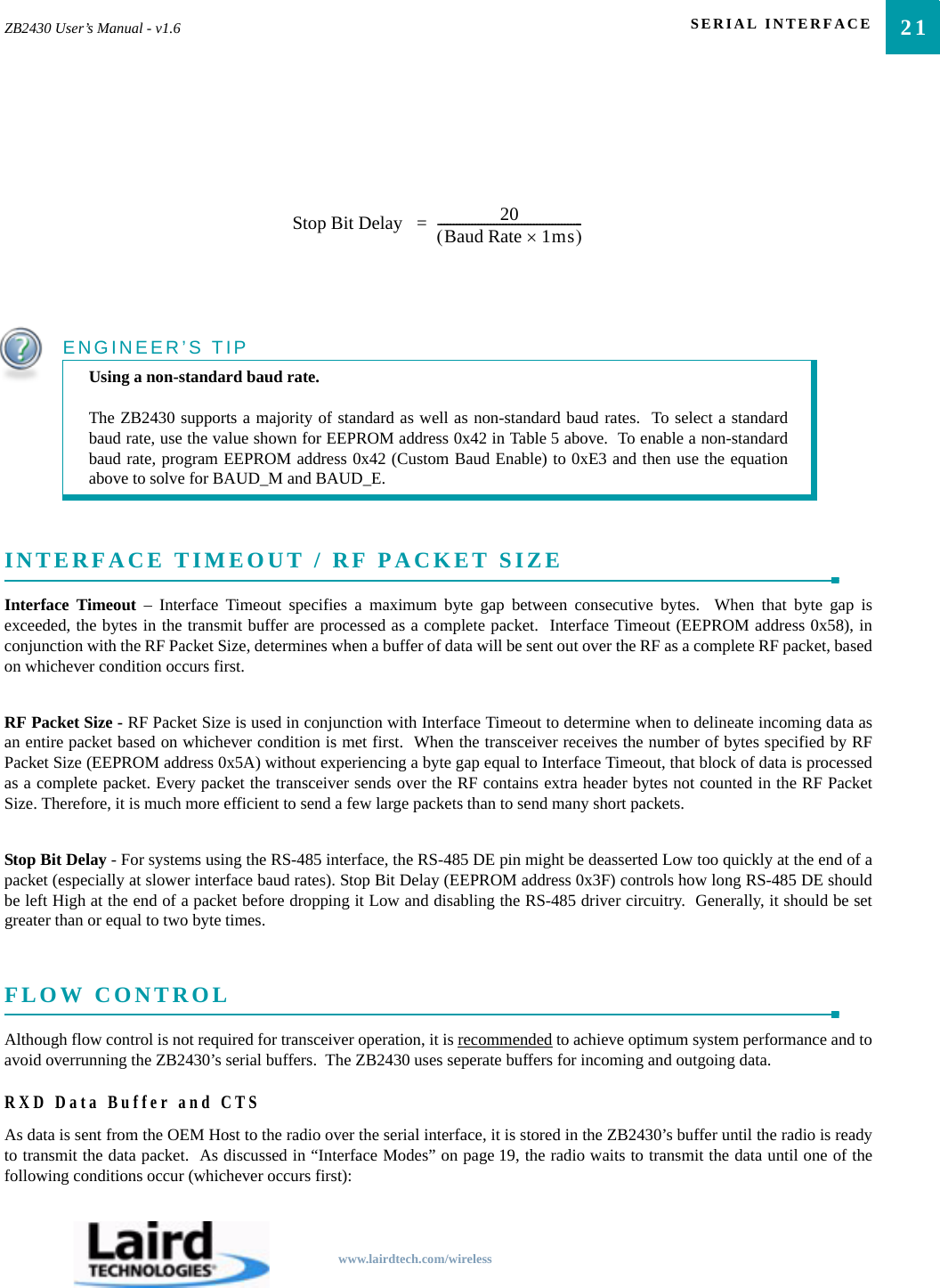
SERIAL INTERFACE20SERIAL INTERFACE BAUD RATEIn order for the OEM Host and a transceiver to communicate over the serial interface they need to have the same serial data rate.This value determines the baud rate used for communicating over the serial interface to a transceiver.    For a baud rate to be valid,the calculated baud rate must be within ±3% of the OEM Host baud rate.For baud rates other than those shown in Table 5 the following equations can be used:Where:FREQUENCY = 32 MHzBAUD_M = EEPROM Address 0x43BAUD_E = EEPROM Address 0x44Table 5: Baud Rate / Interface TimeoutDesired Baud Rate Baud (0x42) Minium Interface Timeout1 (0x58)1. Interface timeout = 1 ms per incrementStop Bit Delay (0x3F)115,200 0x08 0x02 0x0257,600 0x07 0x02 0x0238,40022. Default baud rate0x06 0x02 0x0231,250 0x05 0x02 0x0219,200 0x04 0x02 0x029,600 0x03 0x03 0x034,800 0x02 0x05 0x052,400 0x01 0x09 0x091,200 0x00 0x16 0x16Non-standard 0xE3 Use equations below Use equations below
21ZB2430 User’s Manual - v1.6 SERIAL INTERFACEwww.lairdtech.com/wirelessINTERFACE TIMEOUT / RF PACKET SIZEInterface Timeout – Interface Timeout specifies a maximum byte gap between consecutive bytes.  When that byte gap isexceeded, the bytes in the transmit buffer are processed as a complete packet.  Interface Timeout (EEPROM address 0x58), inconjunction with the RF Packet Size, determines when a buffer of data will be sent out over the RF as a complete RF packet, basedon whichever condition occurs first.RF Packet Size - RF Packet Size is used in conjunction with Interface Timeout to determine when to delineate incoming data asan entire packet based on whichever condition is met first.  When the transceiver receives the number of bytes specified by RFPacket Size (EEPROM address 0x5A) without experiencing a byte gap equal to Interface Timeout, that block of data is processedas a complete packet. Every packet the transceiver sends over the RF contains extra header bytes not counted in the RF PacketSize. Therefore, it is much more efficient to send a few large packets than to send many short packets.Stop Bit Delay - For systems using the RS-485 interface, the RS-485 DE pin might be deasserted Low too quickly at the end of apacket (especially at slower interface baud rates). Stop Bit Delay (EEPROM address 0x3F) controls how long RS-485 DE shouldbe left High at the end of a packet before dropping it Low and disabling the RS-485 driver circuitry.  Generally, it should be setgreater than or equal to two byte times.  FLOW CONTROLAlthough flow control is not required for transceiver operation, it is recommended to achieve optimum system performance and toavoid overrunning the ZB2430’s serial buffers.  The ZB2430 uses seperate buffers for incoming and outgoing data.RXD Data Buffer and CTSAs data is sent from the OEM Host to the radio over the serial interface, it is stored in the ZB2430’s buffer until the radio is readyto transmit the data packet.  As discussed in “Interface Modes” on page 19, the radio waits to transmit the data until one of thefollowing conditions occur (whichever occurs first):ENGINEER’S TIPUsing a non-standard baud rate.The ZB2430 supports a majority of standard as well as non-standard baud rates.  To select a standardbaud rate, use the value shown for EEPROM address 0x42 in Table 5 above.  To enable a non-standardbaud rate, program EEPROM address 0x42 (Custom Baud Enable) to 0xE3 and then use the equationabove to solve for BAUD_M and BAUD_E.Stop Bit Delay  20Baud Rate 1ms×()-----------------------------------------------=
SERIAL INTERFACE22• The RF packet size is reached (EEPROM address 0x5B)• An Interface Timeout occurs (EEPROM address 0x58)After sending the packet over the RF the data continues to be stored in the buffer until the radio receives an RF Acknowledgement(ACK) from the receiving radio (addressed mode), or all transmit retries/broadcast attempts have been utilized.  Once an ACK hasbeen received or all retries/attempts have been exhausted, the current data packet is removed from the buffer and the radio willbegin processing the next data packet in the buffer.To prevent the radio’s RXD buffer from being overrun, it is strongly recommended that the OEM Host monitor the radio’s CTSoutput.  When the number of bytes in the RXD buffer reaches the value specified by CTS_ON (EEPROM address 0x5C), the radiode-asserts (High) CTS to signal to the OEM Host to stop sending data over the serial interface.  CTS is re-asserted after the numberof bytes in the RXD buffer is reduced to the value specified by CTS_OFF (EEPROM address 0x5D); signalling to the OEM Hostthat it may resume sending data to the transceiver.Note: It is recommended that the OEM Host cease all data transmission to the radio while CTS is de-asserted (High); otherwisepotential data loss may occur.TXD Data Buffer and RTSAs data to be forwarded to the OEM Host accumulates, it is stored in the ZB2430’s outgoing buffer until the radio is ready to beginsending the data to the OEM Host.  Once the data packet has been sent to the Host over the serial interface, it will be removed fromthe buffer and the radio will begin processing the next data packet in the buffer.With RTS Mode disabled, the transceiver will send any data to the OEM Host as soon as it has data to send. However, some OEMHosts are not able to accept data from the transceiver all of the time. With RTS Mode Enabled, the OEM Host can prevent thetransceiver from sending it a data by de-asserting RTS (High), causing the transceiver to store the data in its buffer. Once RTS isre-asserted (Low), the transceiver will continue sending data to the OEM Host, beginning with any data stored in its buffer.Note: Leaving RTS de-asserted for too long can cause data loss once the radio’s TXD buffer reaches capacity.NETWORKINGPAN ID - PAN ID (EEPROM address 0x79) is a 16-bit field and is similar to a password or network number and helpsdifferentiate collocated networks. A transceiver will not be associated with a network unless its PAN ID and Channel Numbermatch that of the Coordinator.  Range is 0x0000 to 0x3FFF.RF Channel Number - (EEPROM Address 0x40) Channels 0x0B - 0x1A; 5 MHz spacing.  The transceiver will operate only onthe RF Channel Number specified in the EEPROM.Note: The ZB2430-Q is not approved for use on channel 0x1A and the channel number should therefore be selected accordingly.ENGINEER’S TIPCan I implement a design using just TXD, RXD and Gnd (Three-wire Interface)?Yes.  However, it is strongly recommended that your hardware monitor the CTS pin of the radio.  CTS istaken High by the radio when its interface buffer is getting full.  Your hardware should stop sending atthis point to avoid a buffer overrun (and subsequent loss of data).You can perform a successful design without monitoring CTS.  However, you need to take into accountthe amount of latency the radio adds to the system, any additional latency caused by Transmit Retries,how often you send data, non-delivery network timeouts and interface data rate and the size of thepackets.  Laird Technologies can assist in determining whether CTS is required for your application.
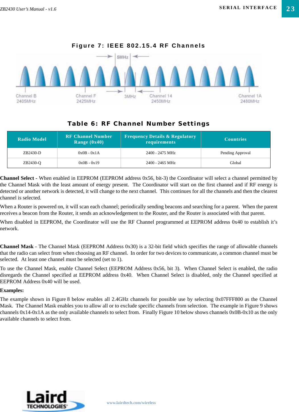
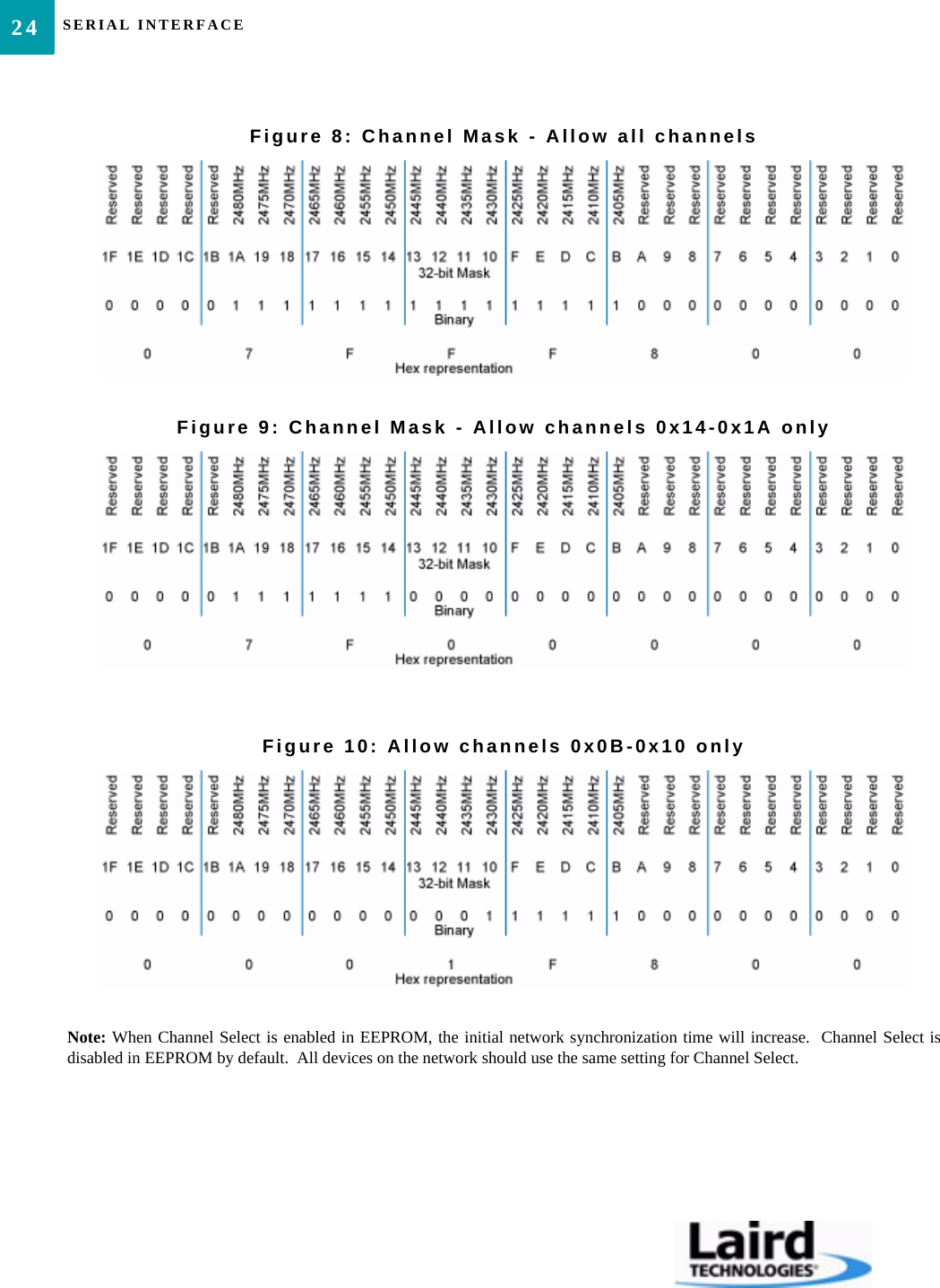
23ZB2430 User’s Manual - v1.6 SERIAL INTERFACEwww.lairdtech.com/wirelessFigure 7: IEEE 802.15.4 RF ChannelsChannel Select - When enabled in EEPROM (EEPROM address 0x56, bit-3) the Coordinator will select a channel permitted bythe Channel Mask with the least amount of energy present.  The Coordinator will start on the first channel and if RF energy isdetected or another network is detected, it will change to the next channel.  This continues for all the channels and then the clearestchannel is selected.When a Router is powered on, it will scan each channel; periodically sending beacons and searching for a parent.  When the parentreceives a beacon from the Router, it sends an acknowledgement to the Router, and the Router is associated with that parent.When disabled in EEPROM, the Coordinator will use the RF Channel programmed at EEPROM address 0x40 to establish it’snetwork.Channel Mask - The Channel Mask (EEPROM Address 0x30) is a 32-bit field which specifies the range of allowable channelsthat the radio can select from when choosing an RF channel.  In order for two devices to communicate, a common channel must beselected.  At least one channel must be selected (set to 1).To use the Channel Mask, enable Channel Select (EEPROM Address 0x56, bit 3).  When Channel Select is enabled, the radiodisregards the Channel specified at EEPROM address 0x40.  When Channel Select is disabled, only the Channel specified atEEPROM Address 0x40 will be used.Examples:The example shown in Figure 8 below enables all 2.4GHz channels for possible use by selecting 0x07FFF800 as the ChannelMask.  The Channel Mask enables you to allow all or to exclude specific channels from selection.  The example in Figure 9 showschannels 0x14-0x1A as the only available channels to select from.  Finally Figure 10 below shows channels 0x0B-0x10 as the onlyavailable channels to select from.Table 6: RF Channel Number SettingsRadio Model RF Channel Number Range (0x40) Frequency Details & Regulatory requirements CountriesZB2430-D 0x0B - 0x1A 2400 - 2475 MHz Pending ApprovalZB2430-Q 0x0B - 0x19 2400 - 2465 MHz Global
SERIAL INTERFACE24Figure 8: Channel Mask - Allow all channelsFigure 9: Channel Mask - Allow channels 0x14-0x1A onlyFigure 10: Allow channels 0x0B-0x10 onlyNote: When Channel Select is enabled in EEPROM, the initial network synchronization time will increase.  Channel Select isdisabled in EEPROM by default.  All devices on the network should use the same setting for Channel Select.
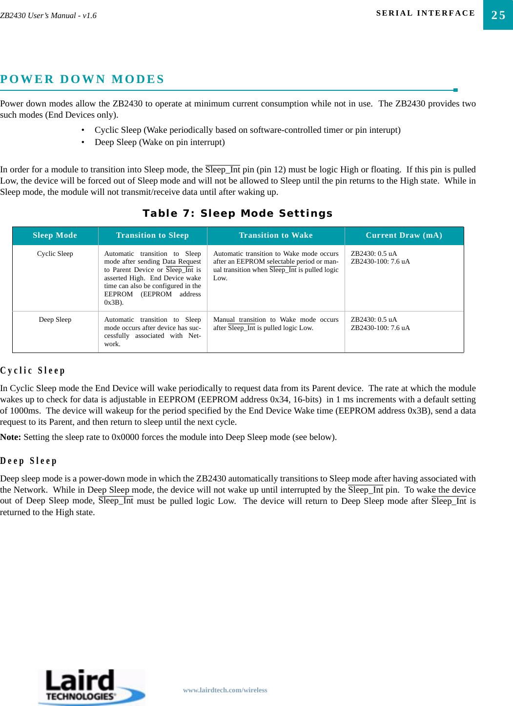
25ZB2430 User’s Manual - v1.6 SERIAL INTERFACEwww.lairdtech.com/wirelessPOWER DOWN MODESPower down modes allow the ZB2430 to operate at minimum current consumption while not in use.  The ZB2430 provides twosuch modes (End Devices only).• Cyclic Sleep (Wake periodically based on software-controlled timer or pin interupt)• Deep Sleep (Wake on pin interrupt)In order for a module to transition into Sleep mode, the Sleep_Int pin (pin 12) must be logic High or floating.  If this pin is pulledLow, the device will be forced out of Sleep mode and will not be allowed to Sleep until the pin returns to the High state.  While inSleep mode, the module will not transmit/receive data until after waking up.Cyclic SleepIn Cyclic Sleep mode the End Device will wake periodically to request data from its Parent device.  The rate at which the modulewakes up to check for data is adjustable in EEPROM (EEPROM address 0x34, 16-bits)  in 1 ms increments with a default settingof 1000ms.  The device will wakeup for the period specified by the End Device Wake time (EEPROM address 0x3B), send a datarequest to its Parent, and then return to sleep until the next cycle.Note: Setting the sleep rate to 0x0000 forces the module into Deep Sleep mode (see below).Deep SleepDeep sleep mode is a power-down mode in which the ZB2430 automatically transitions to Sleep mode after having associated withthe Network.  While in Deep Sleep mode, the device will not wake up until interrupted by the Sleep_Int pin.  To wake the deviceout of Deep Sleep mode, Sleep_Int must be pulled logic Low.  The device will return to Deep Sleep mode after Sleep_Int isreturned to the High state.Table 7: Sleep Mode SettingsSleep Mode Transition to Sleep Transition to Wake Current Draw (mA)Cyclic Sleep Automatic transition to Sleepmode after sending Data Requestto Parent Device or Sleep_Int isasserted High.  End Device waketime can also be configured in theEEPROM (EEPROM address0x3B).Automatic transition to Wake mode occursafter an EEPROM selectable period or man-ual transition when Sleep_Int is pulled logicLow.ZB2430: 0.5 uAZB2430-100: 7.6 uADeep Sleep Automatic transition to Sleepmode occurs after device has suc-cessfully associated with Net-work.Manual transition to Wake mode occursafter Sleep_Int is pulled logic Low. ZB2430: 0.5 uAZB2430-100: 7.6 uA
SERIAL INTERFACE26ENGINEER’S TIPTransmitting and Receiving data with a sleeping End Device.• Data sent to the radio over the UART while it is sleeping will be lost.  If the module wakes while receiving data over the UART, it will only see the data received since waking up.• Incoming RF packets to the module will not keep it awake unless you enable Modify Wake upon RX in EEPROM (EEPROM address 0x45, bit-5).• When sending data for the module to transmit, it is recommended that the module be forced awake using the Sleep_Int pin until the module is finished transmitting the data.  .• While the module is being kept awake using the Sleep_Int pin, it will send data requests to its Parent Device based on the Wake Poll rate specified in EEPROM (EEPROM address 0x3C) for as long as it is awake.• A Parent will only store data for a sleeping End Device for a maximum amount of time specified by the Parent Hold Message EEPROM parameter (EEPROM address 0x39).
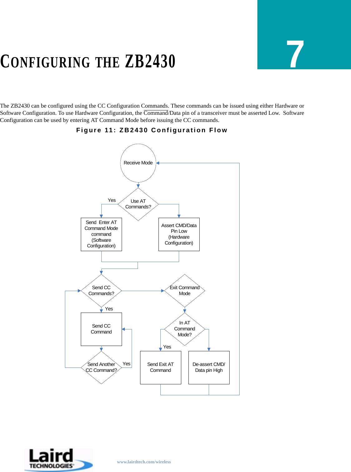
www.lairdtech.com/wirelessCONFIGURING THE ZB24307The ZB2430 can be configured using the CC Configuration Commands. These commands can be issued using either Hardware orSoftware Configuration. To use Hardware Configuration, the Command/Data pin of a transceiver must be asserted Low.  SoftwareConfiguration can be used by entering AT Command Mode before issuing the CC commands.Figure 11: ZB2430 Configuration FlowUse AT Commands?Receive ModeAssert CMD/Data Pin Low (Hardware Configuration)Send  Enter AT Command Mode command (Software Configuration)Send CC Commands? Exit Command ModeIn AT Command Mode?Send CC CommandSend Another CC Command? Send Exit AT Command De-assert CMD/Data pin HighYesYesYesYes
CONFIGURING THE ZB243028AT COMMANDSThe AT Command mode implemented in the ZB2430 creates a virtual version of the Command/Data pin.  The “Enter ATCommand Mode” Command asserts this virtual pin Low (to signify Command Mode) and the “Exit AT Command Mode”Command asserts this virtual pin High (to signify Data).  Once this pin has been asserted Low, all On-the-Fly CC Commandsdocumented in the manual are supported.On-the-Fly Control CommandsThe ZB2430 transceiver contains static memory that holds many of the parameters that control the transceiver operation.  Usingthe “CC” command set allows many of these parameters to be changed during system operation.  Because the memory thesecommands affect is static, when the transceiver is reset, these parameters will revert back to the settings stored in the EEPROM.   While in Command mode, the incoming RF interface of the transceiver is active and packets sent from other transceivers will stillbe received; however no outgoing RF packets will be sent.  The transceiver uses Interface Timeout/RF Packet Size to determinewhen a CC Command is complete.  Therefore, there should be no delay between each character as it is sent from the OEM Host tothe transceiver or the transceiver will not recognize the command.When an invalid command is sent, the radio discards the data and no response is sent to the OEM Host.  Table 8 below shows aquick summary of the basic configuration & diagnostic commands available on the ZB2430.  For detailed command information,please refer to the command descriptions immediatly following the Quick Reference Table.Table 8: Command Quick ReferenceCommand Name Command (All bytes in Hex) Return (All bytes in Hex)Enter AT Command Mode <0x41> <0x54> <0x2B> <0x2B> <0x2B> <0x0D> <0xCC> <0x43> <0x4F> <0x4D>Exit AT Command Mode <0xCC> <0x41> <0x54> <0x4F> <0x0D> <0xCC> <0x44> <0x41> <0x54>Status Request <0xCC> <0x00> <0x00> <0xCC> <Firmware> <Status>Read Channel <0xCC> <0x02> <0xCC> <Channel> <Channel Mask [3-0]>Write Destination NWK Address <0xCC> <0x10> <0x00> <NWK Hi> <NWK Lo> <0xCC> <0x00> <NWK Hi> <NWK Lo>Read Destination NWK Address <0xCC> <0x11> <0xCC> <0x00> <NWK Hi> <NWK Lo>Auto Destination <0xCC> <0x15> <Data> <0xCC> <Data>Read API Control <0xCC> <0x16> <0xCC> <API Control>Write API Control <0xCC> <0x17> <API Control> <0xCC> <API Control>Read Digital Input <0xCC> <0x20> <0xCC> <Data>Read ADC <0xCC> <0x21> <Data> <0xCC> <ADC Hi> <ADC Lo>Write Digital Outputs <0xCC> <0x23> <Data> <0xCC> <Data>Set Power Control <0xCC> <0x25> <Power> <0xCC> <Power>Read NWK Address <0xCC> <0x8A> <0x00> <0xCC> <0x8A> <NWK Hi> <NWK Lo>Read Parent’s NWK Address <0xCC> <0x8A> <0x01> <0xCC> <0x8A> <NWK Hi> <NWK Lo>Discover NWK Address <0xCC> <0x8D>  <MAC [2-0]> <Data> <0xCC> <NWK Hi> <NWK Lo> <Data [n-0]>Discover IEEE Address <0xCC> <0x8E> <NWK Hi> <NWK Lo> <Data> <0xCC> <MAC [7-0]> <Data [n-0]>Read Temperature <0xCC> <0xA4> <0xCC> <Temperature [1-0]>
29ZB2430 User’s Manual - v1.6 CONFIGURING THE ZB2430www.lairdtech.com/wirelessCOMMAND DESCRIPTIONSEEPROM Byte Read <0xCC> <0xC0> <Start> <Length> <0xCC> <Start> <Length> <Data [n-0]>EEPROM Byte Write <0xCC> <0xC1> <Start> <Length> <Data> <Start> <Length> <Last byte written>Soft Reset <0xCC> <0xFF> NoneSoft Reset with NV reset <0xCC> <0xFF> <0xE3> NoneRestore Factory Defaults <0xCC> <0xFF> <0xDF> NoneEnter AT Command ModePrior to sending this command, the OEM Host must ensure that thetransceiver’s RF transmit buffer is empty.   This can be accomplished bywaiting up to one second between the last packet and the AT command.  Ifthe buffer is not empty, the radio will interpret the command as data and itwill be sent over the RF.  Command: <0x41> <0x54> <0x2B> <0x2B> <0x2B> <0x0D>Number of Bytes Returned: 4Response: <0xCC> <0x43> <0x4F> <0x4D>Exit AT Command ModeThe OEM Host should send this command to exit AT Command mode andresume normal operation.Command: <0xCC> <0x41> <0x54> <0x4F> <0x0D>Number of Bytes Returned: 4Response: <0xCC> <0x44> <0x41> <0x54>Status Version RequestThe OEM Host issues this command to request the firmware and link statusof the transceiver.Command: <0xCC> <0x00> <0x00>Number of bytes returned: 3Response: <0xCC> <Firmware> <Type>Parameter Range:<Firmware> = Radio Firmware version eg: 0x17 = v1.7<Type> = 0x00: End Device0x01: Router0x02: Coordinator0x03: Initialized - not started automatically0x04: Initialized - not connected to anything0x05: Discovering PAN’s to join0x06: Joining a PAN0x07: Rejoining a PAN (only for End Devices)0x08: Joined but not yet authenticated0x09: Started a NWK as ZigBee Coordinator0x0A: Device has lost info about its parentRead ChannelTable 8: Command Quick ReferenceCommand Name Command (All bytes in Hex) Return (All bytes in Hex)
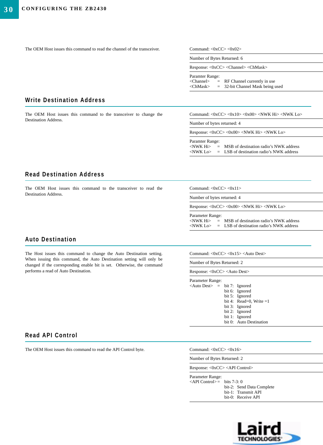
CONFIGURING THE ZB243030The OEM Host issues this command to read the channel of the transceiver. Command: <0xCC> <0x02>Number of Bytes Returned: 6Response: <0xCC> <Channel> <ChMask>Paramter Range:<Channel> = RF Channel currently in use<ChMask> = 32-bit Channel Mask being usedWrite Destination AddressThe OEM Host issues this command to the transceiver to change theDestination Address.Command: <0xCC> <0x10> <0x00> <NWK Hi> <NWK Lo>Number of bytes returned: 4Response: <0xCC> <0x00> <NWK Hi> <NWK Lo>Paramter Range:<NWK Hi> = MSB of destination radio’s NWK address<NWK Lo> = LSB of destination radio’s NWK addressRead Destination AddressThe OEM Host issues this command to the transceiver to read theDestination Address.Command: <0xCC> <0x11>Number of bytes returned: 4Response: <0xCC> <0x00> <NWK Hi> <NWK Lo>Parameter Range:<NWK Hi> = MSB of destination radio’s NWK address<NWK Lo> = LSB of destination radio’s NWK addressAuto DestinationThe Host issues this command to change the Auto Destination setting.When issuing this command, the Auto Destination setting will only bechanged if the corresponding enable bit is set.  Otherwise, the commandperforms a read of Auto Destination.Command: <0xCC> <0x15> <Auto Dest>Number of Bytes Returned: 2Response: <0xCC> <Auto Dest>Parameter Range:<Auto Dest> = bit 7: Ignoredbit 6: Ignoredbit 5: Ignoredbit 4: Read=0, Write =1bit 3: Ignoredbit 2: Ignoredbit 1: Ignoredbit 0: Auto DestinationRead API ControlThe OEM Host issues this command to read the API Control byte. Command: <0xCC> <0x16>Number of Bytes Returned: 2Response: <0xCC> <API Control>Parameter Range:<API Control>= bits 7-3: 0bit-2: Send Data Completebit-1: Transmit APIbit-0: Receive API
31ZB2430 User’s Manual - v1.6 CONFIGURING THE ZB2430www.lairdtech.com/wirelessWrite API ControlThe OEM Host issues this command to write the API Control byte to enableor disable the API features.Command: <0xCC> <0x17> <API Control>Number of Bytes Returned: 2Response: <0xCC> <API Control>Parameter Range:<API Control>= bits 7-3: Ignoredbit-2: Send Data Completebit-1: Transmit APIbit-0: Receive APIRead Digital InputThe OEM Host issues this command to read the state of GI0 input pins.  Pinsconfigured as outputs will report their current state.Command: <0xCC> <0x20>Number of Bytes Returned: 2Response: <0xCC> <Digital In>Parameter Range:<Digital In> = bit-0: GI0Read ADCThe OEM Host issues this command to read the onboard 12-bit A/Dconverters.This command allows a very detailed amount of customization.   The OEMHost can select which pin or sensor to monitor, the resolution of themeasurement and the reference voltage to measure the input ADC against.   Greater Resolution will provide a more detailed response, but will introduceadditional latency.The following equations can be used to determine the voltages associatedwith the ADC value returned:Command:<0xCC> <0x21> <Channel> <Resolution> <Ref>Number of bytes Returned: 3Response: <0xCC> <Hi ADC> <Lo ADC>Parameter Range:<Channel> = 0x00: Cmd/Data0x01: InRange 0x02: GI030x03: GI040x04: GI050x05: GI060x06: GI07 0x07: GI080x0D: Positive Voltage Reference = 1.25V0x0E: Temperature Sensor0x0F: Vdd <Resolution> = 0x00:  8  bit resolution [RES=0x00FF]0x01: 10 bit resoltution[RES=0x03FF]0x02: 12 bit resolution [RES=0x0FFF]0x03: 14 bit resolution [RES=0x3FFF]<Reference> = 0x00: Internal 1.25V  [REFvoltage= 1.25V]0x01: External Reference on GI080x02: Vdd0x03: Differential between pins GI07 and Gi08<Hi ADC> = MSB of requested 12-bit ADC value<Lo ADC> = LSB of requested 12-bit ADC valueWrite Digital OutputsADIn  ADC valueRES[]---------------------------⎝⎠⎛⎞= REFvoltage[]×
CONFIGURING THE ZB243032The OEM Host issues this command to write both digital output lines toparticular states.The OEM Host must write the value of all digital outputs at once.   Each bitrepresents a GIO.   The first 8 bits are resserved and not in use.Command: <0xCC> <0x23> <Digital Out[1-0]>Number of Bytes Returned: 2Response: 0xCC <Digital Out [1-0]>Parameter Range:<Digital Out> = bit-0: GO0bit-1: GO1bit-2: GO2bit-3: GO3bit-4: GO4bit-5: GO5bit-6: GO6bit-7: GO7bit-8-15 : ReservedSet Max PowerThe OEM Host issues this command to adjust the maximum output power. Command: <0xCC> <0x25> <Max Pwr>Number of Bytes Returned: 2Response: 0xCC <Max Pwr>Parameter Range:<Max Pwr> = High Power Low Power0x00: 17 dBm 0x00: 3 dBm0x01: 11 dBm 0x01: -3 dBm0x02: 5 dBm 0x02: -9 dBm0x03: -1 dBm 0x03: -15 dBmRead 16-bit NWK AddressThe OEM Host issues this command to determine the 16-bit NWK addressof the device it is connected to.Command: <0xCC> <0x8A> <0x00>Number of Bytes Returned: 4Response: <0xCC> <0x8A> <NWK Hi> <NWK Lo>Parameter Range:<NWK Hi> = MSB of radio’s NWK address<NWK Lo> = LSB of radio’s NWK addressNote: If the device has not yet been assigned, a NWK address of 0xFFFFwill be returned.Read 16-bit NWK Address of Parent DeviceThe OEM Host issues this command to determine the 16-bit NWK addressof its’ Parent Device.Command: <0xCC> <0x8A> <0x01>Number of Bytes Returned: 4Response: <0xCC> <0x8A> <NWK Hi> <NWK Lo>Parameter Range:<NWK Hi> = MSB of Parent’s NWK address<NWK Lo> = LSB of Parent’s NWK addressNote: If the device has not yet associated, a NWK address of 0xFFFF willbe returned.Discover 16-bit NWK Address of Remote Radio
33ZB2430 User’s Manual - v1.6 CONFIGURING THE ZB2430www.lairdtech.com/wirelessThe OEM Host issues this command to discover the 16-bit NWK address ofa remote radio.Note: This command is valid only for Coordinators and/or Router devices.This command will not issue a response if the requested address is unable tobe located in the network.  A timeout of several seconds should be assumedwhen using this command.Command: <0xCC> <0x8D> <IEEE [7-0]>Number of Bytes Returned: 3Response: <0xCC> <NWK Hi> <NWK Lo> Parameter Range:<IEEE> = 64-bit IEEE Address of remote radio<NWK Hi> = MSB of remote radio’s NWK address<NWK Lo> = LSB of remote radio’s NWK addressDiscover IEEE Address of Remote RadioThe OEM Host issues this command to discover the 64-bit IEEE address ofa remote radio.Note: This command is valid only for Coordinators and/or Router devices.This command will not issue a response if the requested address is unable tobe located in the network.  A timeout of several seconds should be assumedwhen using this command.Command: <0xCC> <0x8E> <0x00> <NWK Hi> <NWK Lo>Number of Bytes Returned: 9Response: <0xCC> <IEEE [7-0]> Parameter Range:<NWK Hi> = MSB of remote radio’s NWK address<NWK Lo> = LSB of remote radio’s NWK address<IEEE> = 64-bit IEEE Address of remote radioDiscover IEEE Address & Children of Remote RadioThe OEM Host issues this command to discover the 64-bit IEEE address ofa remote radio as well as report a list of that device’s Children.Note: This command is valid only for Coordinators and/or Router devices.This command will not issue a response if the requested address is unable tobe located in the network.  A timeout of several seconds should be assumedwhen using this command.Command: <0xCC> <0x8E> <0x00> <NWK Hi> <NWK Lo> <0x01>Number of Bytes Returned: 10+Response: <0xCC> <IEEE [7-0]> <Length> <List>Parameter Range:<NWK Hi> = MSB of remote radio’s NWK address<NWK Lo> = LSB of remote radio’s NWK address<IEEE> = 64-bit IEEE Address of remote radio<Length> = Length of data to follow<List> = List of remote radio’s associated devices [<Index n> <NWK Hi n> <NWK Lo n>]Read TemperatureThe OEM Host issues this command to read the onboard temperature sensor.Note: The temperature sensor is uncalibrated and has a tolerance of +/- 3C.For calibration instructions, contact Laird Technologies’s technical support.Command: <0xCC> <0xA4>Number of bytes returned: 3Response: 0xCC <+/-> <Temp.>Parameter Range:<+/-> = 0x2B: +0x2D: -<Temp.> = Temperature (Celsius) (0x08 - 0x50)Read VoltageThe OEM Hosts issues this command to read the input voltage to the radio. Command: <0xCC>  <0xA6>Number of Bytes Returned: 2Response: <0xCC> <Voltage Integer>  <Voltage Decimal>Parameter Range:<Voltage Integer>=Integer portion of voltage reading<Voltage Decimal>=Decimal portion of voltage readingExample Output: 0xCC 0x03 0x37<0x03> =Integer portion is 3v<0x37> =decimal portion is .55vVoltage level is 3.55V
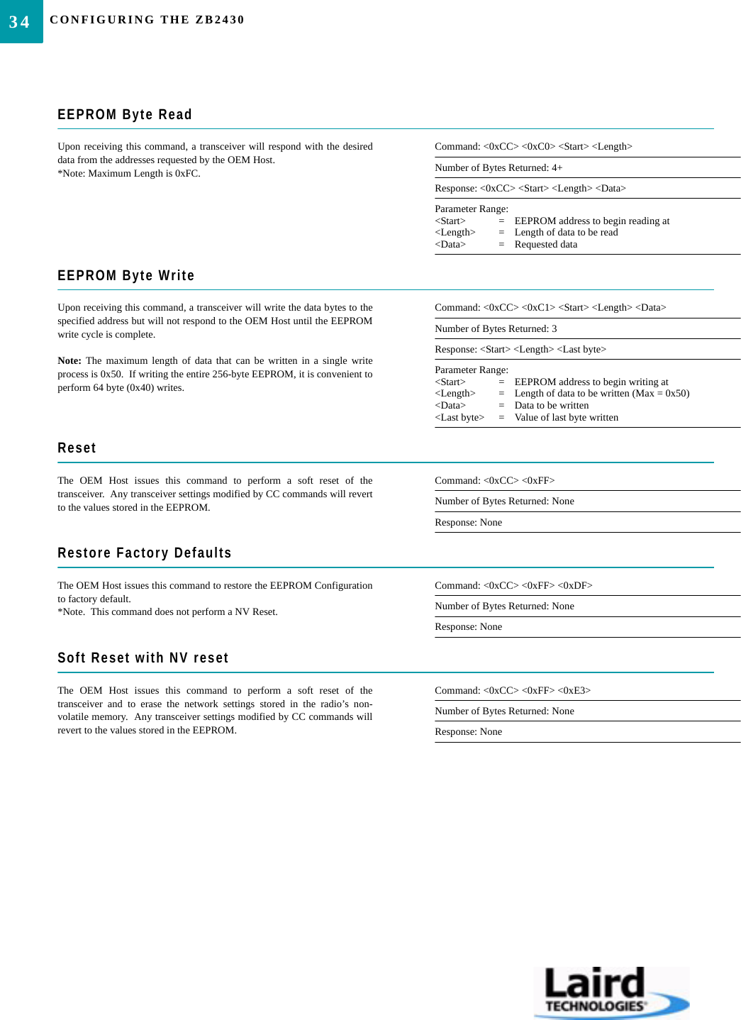
CONFIGURING THE ZB243034EEPROM Byte ReadUpon receiving this command, a transceiver will respond with the desireddata from the addresses requested by the OEM Host.*Note: Maximum Length is 0xFC.Command: <0xCC> <0xC0> <Start> <Length>Number of Bytes Returned: 4+Response: <0xCC> <Start> <Length> <Data>Parameter Range:<Start> = EEPROM address to begin reading at<Length> = Length of data to be read<Data> = Requested dataEEPROM Byte WriteUpon receiving this command, a transceiver will write the data bytes to thespecified address but will not respond to the OEM Host until the EEPROMwrite cycle is complete.Note: The maximum length of data that can be written in a single writeprocess is 0x50.  If writing the entire 256-byte EEPROM, it is convenient toperform 64 byte (0x40) writes.Command: <0xCC> <0xC1> <Start> <Length> <Data>Number of Bytes Returned: 3Response: <Start> <Length> <Last byte>Parameter Range:<Start> = EEPROM address to begin writing at<Length> = Length of data to be written (Max = 0x50)<Data> = Data to be written<Last byte> = Value of last byte writtenResetThe OEM Host issues this command to perform a soft reset of thetransceiver.  Any transceiver settings modified by CC commands will revertto the values stored in the EEPROM.Command: <0xCC> <0xFF>Number of Bytes Returned: NoneResponse: NoneRestore Factory DefaultsThe OEM Host issues this command to restore the EEPROM Configurationto factory default.*Note.  This command does not perform a NV Reset.   Command: <0xCC> <0xFF> <0xDF>Number of Bytes Returned: NoneResponse: NoneSoft Reset with NV resetThe OEM Host issues this command to perform a soft reset of thetransceiver and to erase the network settings stored in the radio’s non-volatile memory.  Any transceiver settings modified by CC commands willrevert to the values stored in the EEPROM.Command: <0xCC> <0xFF> <0xE3>Number of Bytes Returned: NoneResponse: None
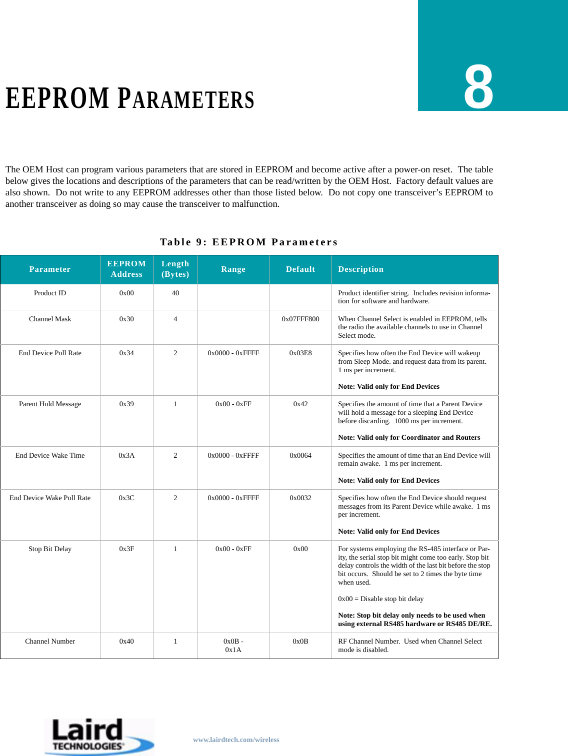
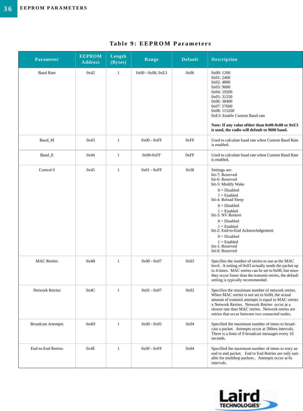
www.lairdtech.com/wirelessEEPROM PARAMETERS8The OEM Host can program various parameters that are stored in EEPROM and become active after a power-on reset.  The tablebelow gives the locations and descriptions of the parameters that can be read/written by the OEM Host.  Factory default values arealso shown.  Do not write to any EEPROM addresses other than those listed below.  Do not copy one transceiver’s EEPROM toanother transceiver as doing so may cause the transceiver to malfunction.Table 9: EEPROM ParametersParameter EEPROM Address Length (Bytes) Range Default DescriptionProduct ID 0x00 40 Product identifier string.  Includes revision informa-tion for software and hardware.Channel Mask 0x30 4 0x07FFF800 When Channel Select is enabled in EEPROM, tells the radio the available channels to use in Channel Select mode.End Device Poll Rate 0x34 2 0x0000 - 0xFFFF 0x03E8 Specifies how often the End Device will wakeup from Sleep Mode. and request data from its parent.  1 ms per increment.Note: Valid only for End DevicesParent Hold Message 0x39 1 0x00 - 0xFF 0x42 Specifies the amount of time that a Parent Device will hold a message for a sleeping End Device before discarding.  1000 ms per increment.Note: Valid only for Coordinator and RoutersEnd Device Wake Time 0x3A 2 0x0000 - 0xFFFF 0x0064 Specifies the amount of time that an End Device will remain awake.  1 ms per increment.Note: Valid only for End DevicesEnd Device Wake Poll Rate 0x3C 2 0x0000 - 0xFFFF 0x0032 Specifies how often the End Device should request messages from its Parent Device while awake.  1 ms per increment.Note: Valid only for End DevicesStop Bit Delay 0x3F 1 0x00 - 0xFF 0x00 For systems employing the RS-485 interface or Par-ity, the serial stop bit might come too early. Stop bit delay controls the width of the last bit before the stop bit occurs.  Should be set to 2 times the byte time when used.0x00 = Disable stop bit delayNote: Stop bit delay only needs to be used when using external RS485 hardware or RS485 DE/RE.Channel Number 0x40 1 0x0B -0x1A 0x0B RF Channel Number.  Used when Channel Select mode is disabled.
EEPROM PARAMETERS36Baud Rate 0x42 1 0x00 - 0x08, 0xE3 0x06 0x00: 12000x01: 24000x02: 48000x03: 96000x04: 192000x05: 312500x06: 384000x07: 576000x08: 1152000xE3: Enable Custom Baud rateNote: If any value ofther than 0x00-0x08 or 0xE3 is used, the radio will default to 9600 baud.Baud_M 0x43 1 0x00 - 0xFF 0xFF Used to calculate baud rate when Custom Baud Rate is enabled.Baud_E 0x44 1 0x00-0xFF 0xFF Used to calculate baud rate when Custom Baud Rate is enabled.Control 0 0x45 1 0x01 - 0xFF 0x38 Settings are:bit-7: Reservedbit-6: Reservedbit-5: Modify Wake0 = Disabled1 = Enabledbit-4: Reload Sleep0 = Disabled1 = Enabledbit-3: NV Restore0 = Disabled1 = Enabledbit-2: End-to-End Acknowledgement0 = Disabled1 = Enabledbit-1: Reservedbit-0: ReservedMAC Retries 0x4B 1 0x00 - 0x07 0x03 Specifies the number of retries to use at the MAC level.  A setting of 0x03 actually sends the packet up to 4 times.  MAC retries can be set to 0x00, but since they occur faster than the transmit retries, the default setting is typically recommended.Network Retries 0x4C 1 0x01 - 0x07 0x02 Specifies the maximum number of network retries.  When MAC retries is not set to 0x00, the actual amount of transmit attempts is equal to MAC retries x Network Retries.  Network Retries  occur at a slower rate than MAC retries.  Network retries are retries that occur between two connected nodes.Broadcast Attempts 0x4D 1 0x00 - 0x05 0x04 Specified the maximum number of times to broad-cast a packet.  Attempts occur at 500ms intervals.  There is a limit of 9 broadcast messages every 10 seconds.End-to-End Retries 0x4E 1 0x00 - 0xFF 0x04 Specified the maximum number of times to retry an end to end packet.   End to End Retries are only suit-able for multihop packets..  Attempts occur at 6s intervals.Table 9: EEPROM ParametersParameter EEPROM Address Length (Bytes) Range Default Description
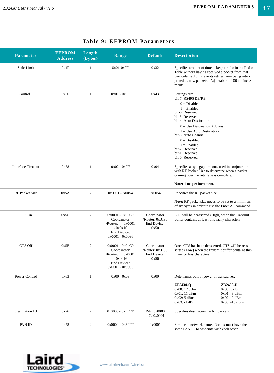
37ZB2430 User’s Manual - v1.6 EEPROM PARAMETERSwww.lairdtech.com/wirelessStale Limit 0x4F 1 0x01-0xFF 0x32 Specifies amount of time to keep a radio in the Radio Table without having received a packet from that particular radio.  Prevents retries from being inter-preted as new packets.  Adjustable in 100 ms incre-ments.Control 1 0x56 1 0x01 - 0xFF 0x43 Settings are:bit-7: RS495 DE/RE0 = Disabled1 = Enabledbit-6: Reservedbit-5: Reservedbit-4: Auto Destination0 = Use Destination Address1 = Use Auto Destinationbit-3: Auto Channel0 = Disabled1 = Enabledbit-2: Reservedbit-1: Reservedbit-0: ReservedInterface Timeout 0x58 1 0x02 - 0xFF 0x04 Specifies a byte gap timeout, used in conjunction with RF Packet Size to determine when a packet coming over the interface is complete.  Note: 1 ms per increment.RF Packet Size 0x5A 2 0x0001 -0x0054 0x0054 Specifies the RF packet size.Note: RF packet size needs to be set to a minimum of six bytes in order to use the Enter AT command.CTS On 0x5C 2 0x0001 - 0x01C0Coordinator /Router:      0x0001 - 0x0416End Device: 0x0001 - 0x0096Coordinator /Router: 0x0190End Device: 0x50CTS will be deasserted (High) when the Transmit buffer contains at least this many charactersCTS Off 0x5E 2 0x0001 - 0x01C0Coordinator /Router:      0x0001 - 0x0416End Device: 0x0001 - 0x0096Coordinator /Router: 0x0180End Device: 0x50Once CTS has been deasserted, CTS will be reas-serted (Low) when the transmit buffer contains this many or less characters.Power Control 0x63 1 0x00 - 0x03 0x00 Determines output power of transceiver.ZB2430-Q ZB2430-D0x00: 17 dBm 0x00: 3 dBm0x01: 11 dBm 0x01: -3 dBm0x02: 5 dBm 0x02: -9 dBm0x03: -1 dBm 0x03: -15 dBmDestination ID 0x76 2 0x0000 - 0xFFFF R/E: 0x0000   C: 0x0001 Specifies destination for RF packets.PAN ID 0x78 2 0x0000 - 0x3FFF 0x0001 Similar to network name.  Radios must have the same PAN ID to associate with each other.Table 9: EEPROM ParametersParameter EEPROM Address Length (Bytes) Range Default Description
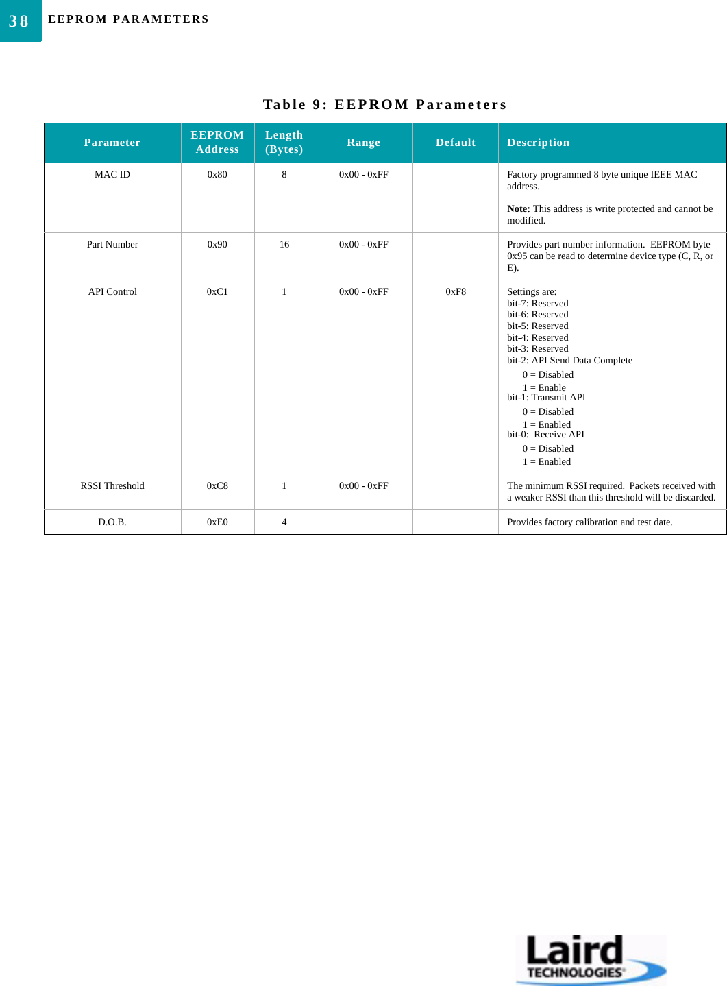
EEPROM PARAMETERS38MAC ID 0x80 8 0x00 - 0xFF Factory programmed 8 byte unique IEEE MAC address.Note: This address is write protected and cannot be modified.Part Number 0x90 16 0x00 - 0xFF Provides part number information.  EEPROM byte 0x95 can be read to determine device type (C, R, or E).API Control 0xC1 1 0x00 - 0xFF 0xF8 Settings are:bit-7: Reservedbit-6: Reservedbit-5: Reservedbit-4: Reservedbit-3: Reservedbit-2: API Send Data Complete0 = Disabled1 = Enablebit-1: Transmit API0 = Disabled1 = Enabledbit-0:  Receive API0 = Disabled1 = EnabledRSSI Threshold 0xC8 1 0x00 - 0xFF The minimum RSSI required.  Packets received with a weaker RSSI than this threshold will be discarded.D.O.B. 0xE0 4 Provides factory calibration and test date.Table 9: EEPROM ParametersParameter EEPROM Address Length (Bytes) Range Default Description
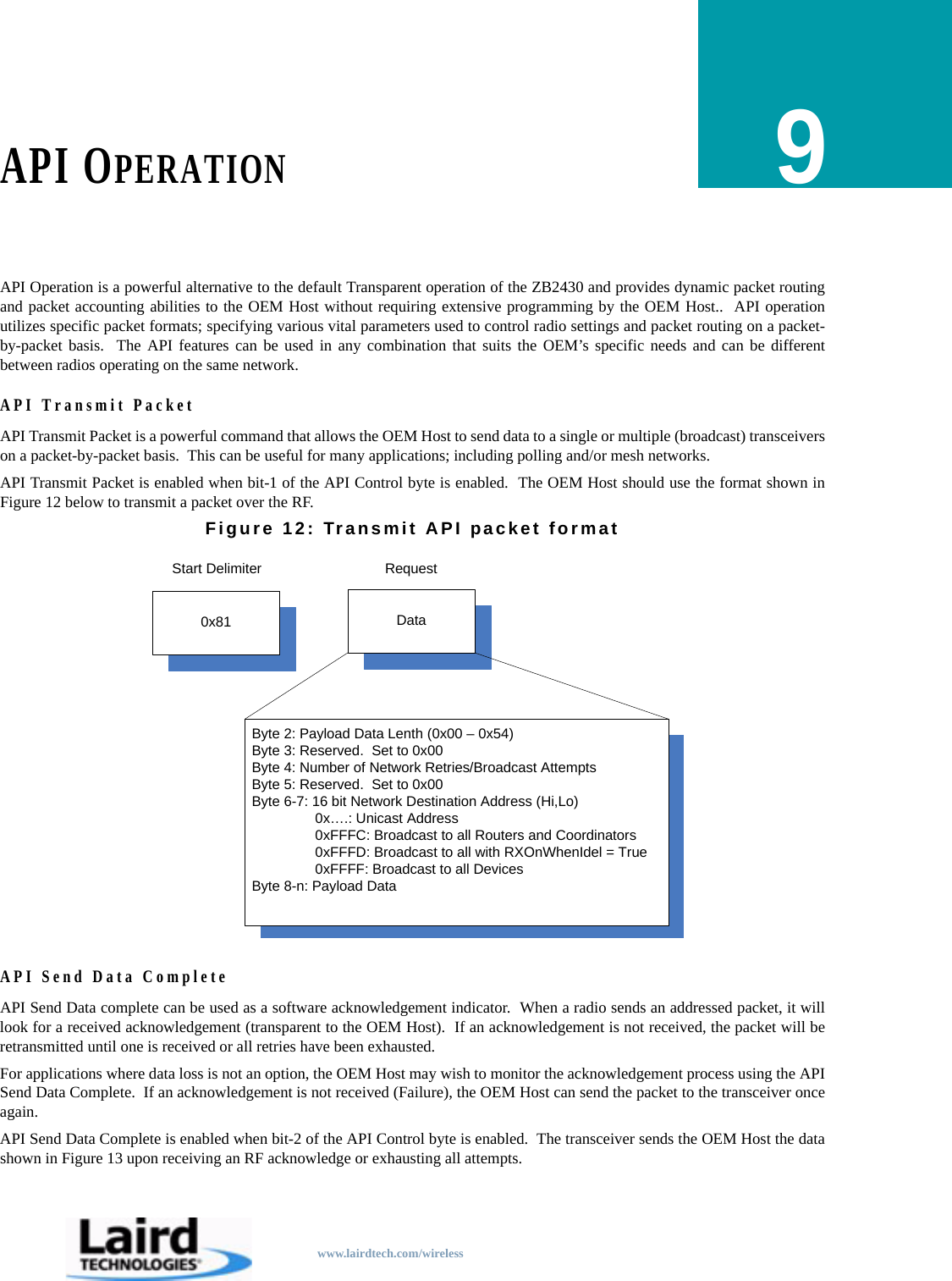
www.lairdtech.com/wirelessAPI OPERATION9API Operation is a powerful alternative to the default Transparent operation of the ZB2430 and provides dynamic packet routingand packet accounting abilities to the OEM Host without requiring extensive programming by the OEM Host..  API operationutilizes specific packet formats; specifying various vital parameters used to control radio settings and packet routing on a packet-by-packet basis.  The API features can be used in any combination that suits the OEM’s specific needs and can be differentbetween radios operating on the same network.API Transmit PacketAPI Transmit Packet is a powerful command that allows the OEM Host to send data to a single or multiple (broadcast) transceiverson a packet-by-packet basis.  This can be useful for many applications; including polling and/or mesh networks.API Transmit Packet is enabled when bit-1 of the API Control byte is enabled.  The OEM Host should use the format shown inFigure 12 below to transmit a packet over the RF.Figure 12: Transmit API packet formatAPI Send Data CompleteAPI Send Data complete can be used as a software acknowledgement indicator.  When a radio sends an addressed packet, it willlook for a received acknowledgement (transparent to the OEM Host).  If an acknowledgement is not received, the packet will beretransmitted until one is received or all retries have been exhausted.For applications where data loss is not an option, the OEM Host may wish to monitor the acknowledgement process using the APISend Data Complete.  If an acknowledgement is not received (Failure), the OEM Host can send the packet to the transceiver onceagain.API Send Data Complete is enabled when bit-2 of the API Control byte is enabled.  The transceiver sends the OEM Host the datashown in Figure 13 upon receiving an RF acknowledge or exhausting all attempts.DataRequest0x81Start DelimiterByte 2: Payload Data Lenth (0x00 – 0x54)Byte 3: Reserved.  Set to 0x00Byte 4: Number of Network Retries/Broadcast AttemptsByte 5: Reserved.  Set to 0x00Byte 6-7: 16 bit Network Destination Address (Hi,Lo)0x….: Unicast Address0xFFFC: Broadcast to all Routers and Coordinators0xFFFD: Broadcast to all with RXOnWhenIdel = True0xFFFF: Broadcast to all DevicesByte 8-n: Payload Data
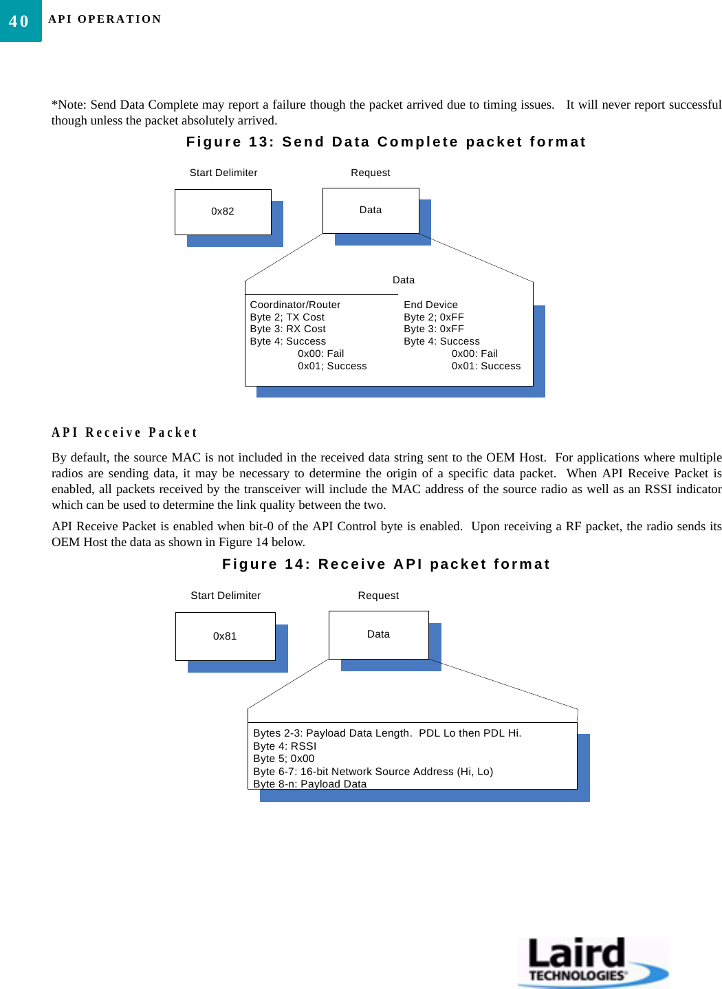
API OPERATION40*Note: Send Data Complete may report a failure though the packet arrived due to timing issues.   It will never report successfulthough unless the packet absolutely arrived.Figure 13: Send Data Complete packet formatAPI Receive PacketBy default, the source MAC is not included in the received data string sent to the OEM Host.  For applications where multipleradios are sending data, it may be necessary to determine the origin of a specific data packet.  When API Receive Packet isenabled, all packets received by the transceiver will include the MAC address of the source radio as well as an RSSI indicatorwhich can be used to determine the link quality between the two.API Receive Packet is enabled when bit-0 of the API Control byte is enabled.  Upon receiving a RF packet, the radio sends itsOEM Host the data as shown in Figure 14 below.Figure 14: Receive API packet formatDataRequest0x82Start DelimiterDataCoordinator/RouterByte 2; TX CostByte 3: RX CostByte 4: Success0x00: Fail0x01; SuccessEnd DeviceByte 2; 0xFFByte 3: 0xFFByte 4: Success0x00: Fail0x01: SuccessDataRequest0x81Start DelimiterBytes 2-3: Payload Data Length.  PDL Lo then PDL Hi.Byte 4: RSSIByte 5; 0x00Byte 6-7: 16-bit Network Source Address (Hi, Lo)Byte 8-n: Payload Data
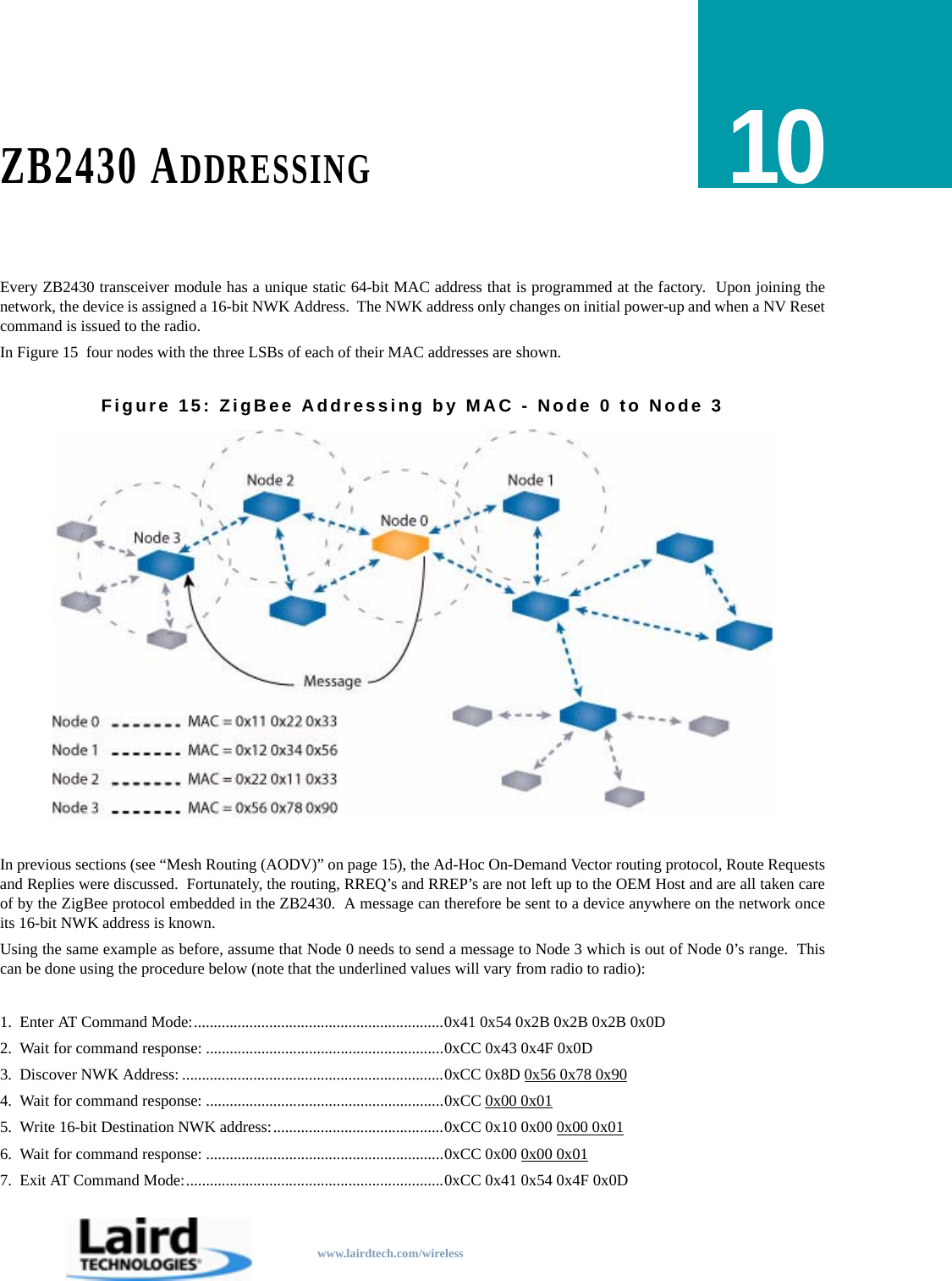
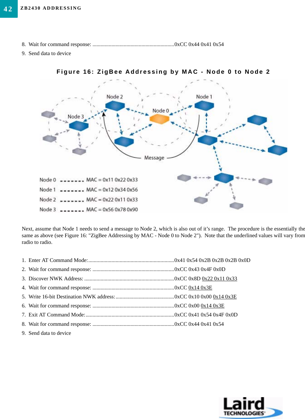
www.lairdtech.com/wirelessZB2430 ADDRESSING10Every ZB2430 transceiver module has a unique static 64-bit MAC address that is programmed at the factory.  Upon joining thenetwork, the device is assigned a 16-bit NWK Address.  The NWK address only changes on initial power-up and when a NV Resetcommand is issued to the radio.In Figure 15  four nodes with the three LSBs of each of their MAC addresses are shown.Figure 15: ZigBee Addressing by MAC - Node 0 to Node 3In previous sections (see “Mesh Routing (AODV)” on page 15), the Ad-Hoc On-Demand Vector routing protocol, Route Requestsand Replies were discussed.  Fortunately, the routing, RREQ’s and RREP’s are not left up to the OEM Host and are all taken careof by the ZigBee protocol embedded in the ZB2430.  A message can therefore be sent to a device anywhere on the network onceits 16-bit NWK address is known.Using the same example as before, assume that Node 0 needs to send a message to Node 3 which is out of Node 0’s range.  Thiscan be done using the procedure below (note that the underlined values will vary from radio to radio):1.  Enter AT Command Mode:...............................................................0x41 0x54 0x2B 0x2B 0x2B 0x0D2.  Wait for command response: ............................................................0xCC 0x43 0x4F 0x0D3.  Discover NWK Address: ..................................................................0xCC 0x8D 0x56 0x78 0x904.  Wait for command response: ............................................................0xCC 0x00 0x015.  Write 16-bit Destination NWK address:...........................................0xCC 0x10 0x00 0x00 0x016.  Wait for command response: ............................................................0xCC 0x00 0x00 0x017.  Exit AT Command Mode:.................................................................0xCC 0x41 0x54 0x4F 0x0D
ZB2430 ADDRESSING428.  Wait for command response: ............................................................0xCC 0x44 0x41 0x549.  Send data to deviceFigure 16: ZigBee Addressing by MAC - Node 0 to Node 2Next, assume that Node 1 needs to send a message to Node 2, which is also out of it’s range.  The procedure is the essentially thesame as above (see Figure 16: "ZigBee Addressing by MAC - Node 0 to Node 2").  Note that the underlined values will vary fromradio to radio.1.  Enter AT Command Mode:...............................................................0x41 0x54 0x2B 0x2B 0x2B 0x0D2.  Wait for command response: ............................................................0xCC 0x43 0x4F 0x0D3.  Discover NWK Address: ..................................................................0xCC 0x8D 0x22 0x11 0x334.  Wait for command response: ............................................................0xCC 0x14 0x3E5.  Write 16-bit Destination NWK address:...........................................0xCC 0x10 0x00 0x14 0x3E6.  Wait for command response: ............................................................0xCC 0x00 0x14 0x3E7.  Exit AT Command Mode:.................................................................0xCC 0x41 0x54 0x4F 0x0D8.  Wait for command response: ............................................................0xCC 0x44 0x41 0x549.  Send data to device
www.lairdtech.com/wirelessADVANCED NETWORK COMMANDS11Some applications may require a more extensive knowledge of the Network and its current configuration.  For this reason, theZB2430 includes several advanced commands which can be issued anytime the radio is in Command mode.  Each of thesecommands include a 16-bit Return Mask which allows the OEM Host to select the information returned in the command response.Note: All unused bits in the Return Mask should be set to “0”.Read Neighbor TableThe Neighbor Table is stored in NV RAM in stores information about neighboring devices which are operating with teh sameChannel Mask, but no necessarily the same channel.  This command is not available on End Devices. The command format isshown in Figure 17.Command Definitions• Start Index: Starting index within the Neighbor Table to begin reporting.• Count: Number of entries to include in Neighbor Table.  Maximum number of indexes = 8 (Coordinator and Routers) and 4 (End Devices).• Index Number: Index location of radio in Route Table.• NWK Address: 16-bit NWK address of the neighboring device.• PAN ID: The 16-bit PAN ID of the network to which the device belongs.• TX Cost: Counter of transmission (success/failures)• RX Cost: Average of received RSSI values for the specified deviceFigure 17: Read Neighbor Table CommandAfter issuing the Read Neighbor Table command, the radio will respond with the requested information as shown in Figure 18below.  The actual command response format may vary depending on the Return Mask setting used in the command.*Note: Command will only fail if more than the maximum number of neighbors is requested.   0x00: Index to start reporting atStart Index (Byte 4)DataRequest0xCCStart Delimiter0x88Command IdentifierReturn Mask (Bytes 5-6)Count (Byte 3)0x00: Show all Entries between Start index and Maximum (Max = 8 for Coordinators/Routers, Max = 4 for End Devices)0x01-n: Show Entries between Start Index and Start Index + Count – 1.Bit 0: Index NumberBit 1: Network AddressBit 2: PAN IDBit 3: TX CostBit 4: RX CostBit 5: Security Key Sequence NumberBit 6: Security Frame CounterBit 7-15: Reserved.  Set to 0.
ADVANCED NETWORK COMMANDS44Figure 18: Read Neighbor Table ResponseRead Route TableZigBee Coordinators and Routers maintain a routing table in memory which is used to establish a route to a particular destinationdevice.Note: This command is not valid for End Devices.Command Definitions• Count: Number of entries to include in Route Table.  Maximum number of indexes = 20 • Start Index: Starting index within the Route Table to begin reporting.• Index Number: Index location of radio in Route Table.• Destination Address: The 16-bit NWK address of the route.• Next Hop Address: The 16-bit NWK address of the next radio on the way to the destination.• Expiry Time: A countdown timer indicating the number of seconds until route expires.  Expiry Time is set to 0x1E (30s) when a new route is created.• Status: The status of the route.• Command will faile if the maximum requested entries is greater than 20.0x00: Success0x01: FailStatus (Byte 4)DataRequest0xCCStart Delimiter0x88Command Identifier1 ByteLengthSuccess:Byte 5: Index numberBytes 6-7: NWK AddressBytes 8-9: PAN IDByte 10: TX CostByte 11: RX CostByte 12: Security Key Sequence numberBytes 13-16: Security Frame CounterFailure: Byte 5: Max Neighbor EntriesResponse (Bytes 5-n)(Repeated for each radio)
45ZB2430 User’s Manual - v1.6 ADVANCED NETWORK COMMANDSwww.lairdtech.com/wirelessFigure 19: Read Route Table CommandFigure 20: Read Route Table ResponsePerform ScanZigBee Coordinators and Routers can manually scan selected channels for RF activity and other ZigBee devices/PAN ID’s, etc.Note: This command not valid for End Devices.Command Definitions• Scan Channel: A 32-bit channel mask specifying the channel(s) to include in the scan.• Scan Type: Specifies the type of scan to perform.  Energy scan, the device will tune to each channel & perform an energy measurement.  Active scan, the device tunes to each channel, sends a beacon request and listen for beacons from other ZigBee devices.• Scan Duration: Duration of the Active & Energy scans on each channel selected.  Time is measured as:(15.36ms) x 2^(Scan Duration + 1)• Max Results: The maximum number of results to report for Active scans.  Ignored with Energy scan command.• Status:  Indicates the status of the current scan.• Channel Number: 8-bit channel current measurement was taken from.• Energy: The strength of the RF channel during the Energy scan.0x00: Index to start reporting fromStart Index (Byte 4)DataRequest0xCCStart Delimiter0x89Command IdentifierReturn Mask (Bytes 5-6)Bit 0: Index numberBit 1: Destination AddressBit 2: Next Hop AddressBit 3: Expiry TimeBit 4: StatusBits 5-15: Reserved.  Set to 0.0x00: Show all Entries between Start index and Maximum (Max = 8 for Coordinators/Routers, Max = 4 for End Devices)0x01-n: Show Entries between Start Index and Start Index + Count – 1.0x00: Success0x01: FailStatus (Byte 4)DataRequest0xCCStart Delimiter0x89Command Identifier1 ByteLengthResponse (Bytes 5-n)Reported for each radioSuccess:Byte 5: Index NumberBytes 6-7: Destination AddressBytes 8-9: Next Hop AddressByte 10: Expiry TimeByte 11: StatusFailure:Byte 5: Max Route Entries (20)
ADVANCED NETWORK COMMANDS46• NWK Address: 16-bit NWK address of the neighboring device.• PAN ID: The 16-bit PAN ID of the network to which the device belongs.• Link Quality: The strength of the link between the current device and the device found during the Active scan.Figure 21: Perform Scan Command32-bit channel mask describing channels to scanScan Channel (Bytes 3-6)0x00: Energy detect scan0x01: Active scanScan Type (Byte 7)DataRequest0xCCStart Delimiter0x8BCommand IdentifierRange: 0x00-0x0EScan Duration (Byte 8)Reserved.Set to 0x00.Reserved (Byte 9)Maximum number of results to returnMax Results (Byte 10)
47ZB2430 User’s Manual - v1.6 ADVANCED NETWORK COMMANDSwww.lairdtech.com/wirelessFigure 22: Perform Scan ResponseRead Radio TableThe Radio Table, stored in NV RAM, contains information about any parent or children it is associated with.  The Radio Tablestores relationship and link-state information which updates everytime the radio receives a packet from that device.  To read adevice’s Radio Table, use the command format shown in Figure 23 below.Note: This command not valid for End Devices.Command Definitions• Index Number: Index location of radio in Radio Table (range = 0-20).• NWK Address: 16-bit NWK address of the device.• Node Relation: The type/relation of the device.• Device Status: Status of the link between the two devices.• TX Cost: Counter of transmission (success/failures).  Failures are incremented on fail and decremented on success.  Range is 0x00 - 0x07.• RX Cost: Average of received RSSI values for the specified deviceDataRequest0xCCStart Delimiter0x8BCommand Identifier1 ByteLength0x00: Energy detect scan0x01: Active scanScan Type (Byte 6) Reserved (Byte 7)0x00: Success0x1A: Fail – Insufficient RAM Resources0xFC: Scan already in progressStatus (Byte 5)if Scan Type = 0x00Byte 8: Channel NumberByte 9: Energyif Scan Type = 0x01Byte 8: Channel NumberBytes 9-10: NWK AddressBytes 11-12: PAN IDByte 13: Link QualityResponse (Bytes 8-n)Reserved: 0x00
ADVANCED NETWORK COMMANDS48Figure 23: Read Radio Table CommandAfter issuing the Read Radio Table command, the radio will respond with the requested information as shown in Figure 24 below.The actual command response format may vary depending on the Return Mask setting used in the command.Figure 24: Read Radio Table Response0x00: All0x01: Parent0x02: Children0x03: Radio at indexDevice Type (Byte 3)Radio Index in table.  (Only valid when Device Type = 0x03)Index (Byte 4)DataRequest0xCCStart Delimiter0x8CCommand IdentifierReturn Mask (Bytes 5-6)Bit 0: Index numberBit 1: NWK AddressBit 2: Address indexBit 3: Node relationBit 4: Device StatusBit 5: Association CountBit 6: TX costBit 7: RX costBit 8: Security Key sequence numberBit 9: Security Frame counterBits 10-15: Reserved.  Set to 0.0x00: SuccessStatus (Byte 4)DataRequest0xCCS ta rt D e lim ite r0x8CC o m m an d  Id e n tifier1 ByteLengthByte 5: Index numberBytes 6-7: NW K AddressBytes 8-9: Address indexByte 10: Node relation0x00: Parent0x01: Child RFD0 x 0 2 : C h ild  R F D  R X  Id le0x03: Child FFD0 x 0 4 : C h ild  F F D  R X  Id le0x05: N eighbor0x06: O ther0xFF: Not usedByte 11: Device Status0x00: End D evice0x01: Router0x02: Coordinator0x03: Initialized- not started autom atically0 x 0 4 : In itia lize d -n o t c o n n e c te d  to  a n y th in g0 x 0 5 : D is c o ve rin g  P A N ’s  to  jo in0x06: Joining a PAN0x07: Rejoining a PAN (only for End Devices)0 x 0 8 : J o in e d  b u t n o t y e t a u th e n tic ate d0x09: Started a N W K as ZigBee C oordinator0 x 0 A : D e v ic e  h a s  lo s t in fo  a b o u t its  p a re n tByte 12: Association C ountByte 13: TX CostByte 14: RX C ostByte 15: Security Key Sequence num berBytes 16-19: Security Fram e CounterResponse (Bytes 5-n)(R epeated for each radio)
49ZB2430 User’s Manual - v1.6 ADVANCED NETWORK COMMANDSwww.lairdtech.com/wireless
www.lairdtech.com/wirelessDIMENSIONS12ZB2430 MECHANICALFigure 25: ZB2430 Mechanical DrawingNotes:All dimensions are +/- .005 inchesPC Board Material is 0.031 thick FR4Board edge connections are 1/2 of 0.031 plated holes0.0150.2050.8371.3500.0000.079typ.0.0150.0000.3810.9851.0000.0000.0310.131Top ViewSide ViewBottom View18 10192219RF ShieldBottom Pads0.060 by 0.050 typ.0.8100.6191.0400.3250.0000.7600.675
www.lairdtech.com/wirelessORDERING INFORMATION13PRODUCT PART NUMBERS
www.lairdtech.com/wirelessCOMPLIANCY INFORMATION14AGENCY IDENTIFICATION NUMBERSAgency compliancy is a very important requirement for any product development.  Laird Technologies is in the process ofobtaining modular approval for its ZB2430 product family so that the OEM only needs to meet a few requirements to use thatapproval.  The corresponding agency identification numbers and approved antennas are listed below.APPROVED ANTENNA LISTThis device has been designed to operate with the antennas listed below, and having a maximum gain of 5dB.  Antennas notincluded in this list or having a gain greater than 5dB are strictly prohibited for use with this device.  The required antennaimpedance is 50 ohms.Contains FCC ID: KQL-ZB2430-100 / KQL-ZB2430D/KQL-Z100S1XFXThe enclosed device complies with Part 15 of the FCC Rules.  Operation is subject to the following two conditions: (1) This device may not cause harmfulinterference, and (2) This device must accept any interference received, including interference that may cause undesired operation.Table 10: Agency Identification NumbersPart Number US/FCC CANADA/IC ETSIZB2430-D KQL-ZB2430D 2268C-ZB2430D ApprovedZB2430-100 KQL-ZB2430-100 2268C-ZB2430 PendingZ100S1 Family KQL-Z100S1XFX 2268C-Z100S1XF ApprovedTable 11: ZB2430 Approved Antenna ListLaird Technologies Part Number Manufacturer Part Number Manufacturer11.The OEM is free to choose an antenna another vendor’s antenna of the same type with equal or lesser gain.Type  Gain (dBi)ZB2430-DZB2430-100Z100S1 Family-FR05-S1-N-o-001 Fractus Integral Chip 2 - X -0600-00039 S151FC-L-(132)PX-2450S Nearson Omni 5 X X XWIC2450-A Laird/Centurion Chip 2 X - X
53ZB2430 User’s Manual - v1.6 COMPLIANCY INFORMATIONwww.lairdtech.com/wirelessFCC / IC REQUIREMENTS FOR MODULAR APPROVALIn general, there are two agency classifications of wireless applications; portable and mobile.Portable - Portable is a classification of equipment where the user, in general, will be within 20 cm of the transmitting antenna.Portable equipment is further broken down into two classes; within 2.5 cm of human contact and beyond 2.5 cm (Note: Ankles,feet, wrists, and hands are permitted to be within 2.5 cm of the antenna even if the equipment is designated as being greater than2.5 cm).  The ZB2430 is not agency approved for portable applications.  The OEM is required to have additional testing performedto receive this classification.  Contact Laird Technologies for more details.Mobile - Mobile defines equipment where the user will be 20 cm or greater from the transmitting equipment.  The antenna must bemounted in such a way that it cannot be moved closer to the user with respect to the equipment, although the equipment may bemoved.  (Note:  Ankles, feet, wrists, and hands are permitted to be within 20 cm of mobile equipment).OEM EQUIPMENT LABELING REQUIREMENTSWARNING: The OEM must ensure that FCC labeling requirements are met.  This includes a clearly visible label on the outside ofthe OEM enclosure specifying the appropriate Laird Technologies FCC identifier for this product as well as the FCC notice below.The FCC identifiers are listed above.Label and text information should be in a size of type large enough to be readiily legible, consistent with the dimensions of theequipment and the label.  However, the type size for the text is not required to be larger than eight point.ANTENNA REQUIREMENTSTo reduce potential radio interence to other users, the antenna type and it’s gain should be so chosen that the equivalentisotropically radiated power (e.i.r.p.) is not more than that permitted for successful communication. WARNING: This device has been tested with a U.FL connector with the above listed antennas.  When integrated into the OEM’sproduct, these fixed antennas require professional installation preventing end-users from replacing them with non-approvedantennas.  Any antenna not listed in the above table must be tested to comply with FCC Section 15.203 for unique antennaconnectors and Section 15.247 for emissions.  Contact Laird Technologies for assistance.Caution: This equipement complies with part 15 of the FCC Rules. Any changes or modifications not expressly approvedby Laird Technologies could void the user’s authority to operate the equipment.WARNINGS REQUIRED IN OEM MANUALSWARNING: This equipment has been approved for mobile applications where the equipment should be used at distances greaterthan 20 cm from the human body (with the exception of hands, feet, wrists, and ankles).  Operation at distances of less than 20 cmis strictly prohibited and requires additional SAR testing.Contains FCC ID: KQL-ZB2430-100 / KQL-ZB2430D / KQL-Z100S1XFXThe enclosed device complies with Part 15 of the FCC Rules.  Operation is subject to the following two conditions: (1) This device may not cause harmfulinterference, and (2) This device must accept any interference received, including interference that may cause undesired operation.
COMPLIANCY INFORMATION54CHANNEL WARNINGThe OEM must prevent the end-user from selecting a channel not approved for use by the FCC.
55ZB2430 User’s Manual - v1.6 COMPLIANCY INFORMATIONwww.lairdtech.com/wireless

Navigation menu