Laird Connectivity ZB2430D RF Transceiver Module User Manual ZB2430 User s Manual
AeroComm Corporation RF Transceiver Module ZB2430 User s Manual
UserManual.wiki
>
Laird Connectivity
>
ZB2430D User Manual
User Manual
Navigation menu
Upload a User Manual
Namespaces
Wiki Guide
HTML
PDF
Info
Views
User Manual
Discussion / Help
Navigation


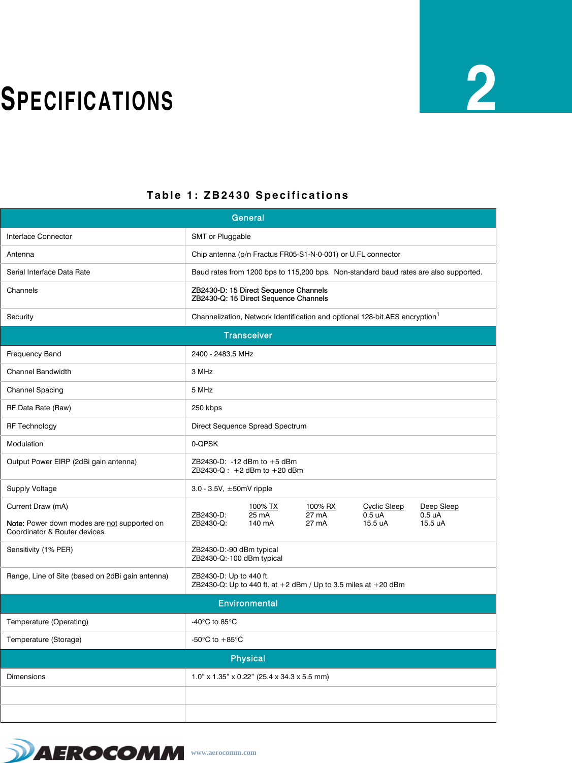


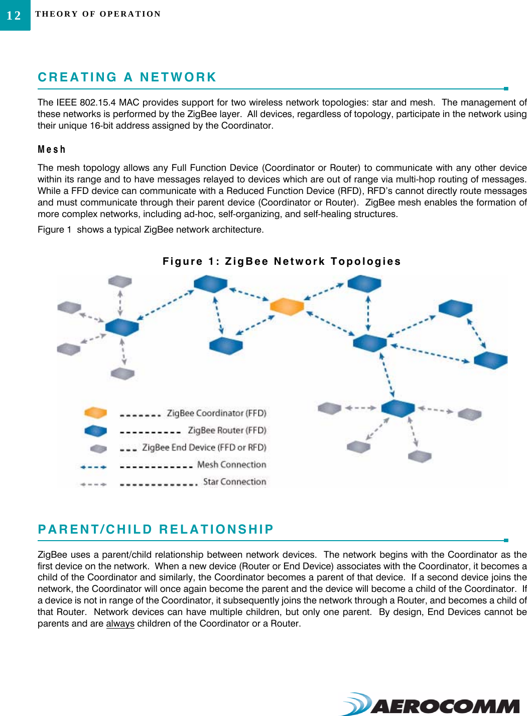
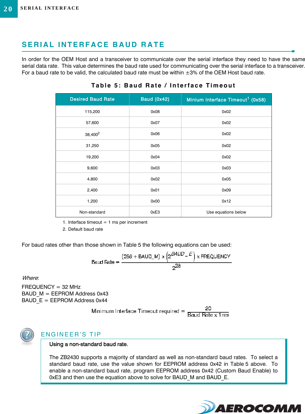

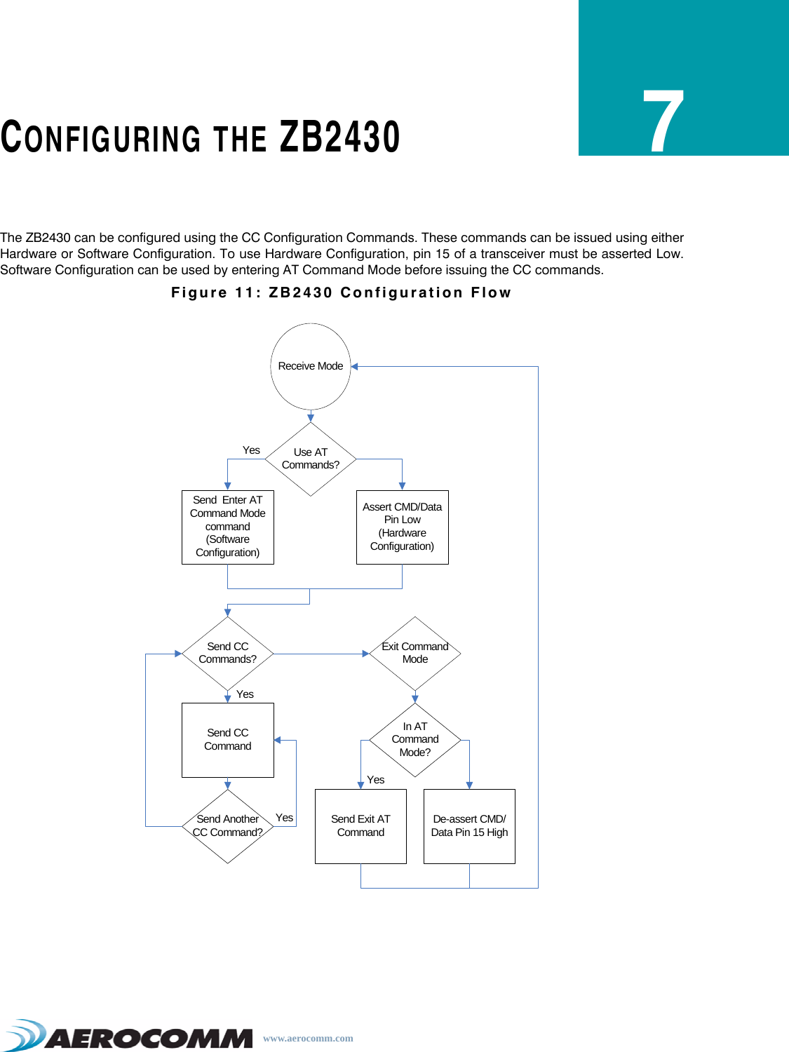
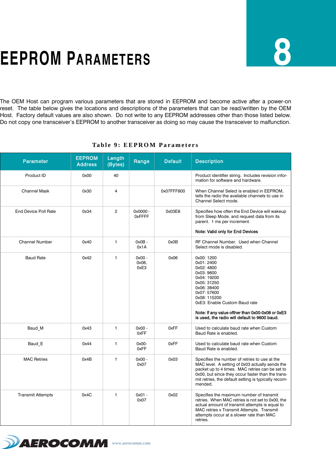
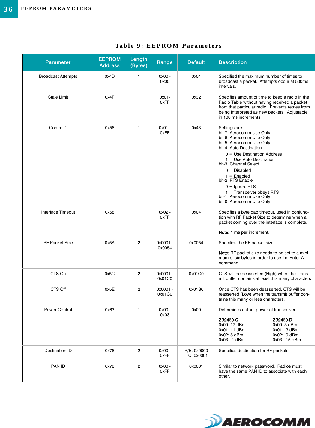
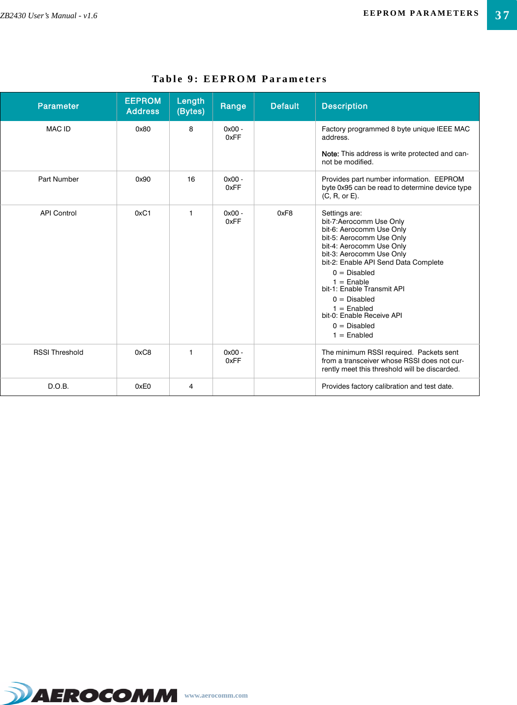
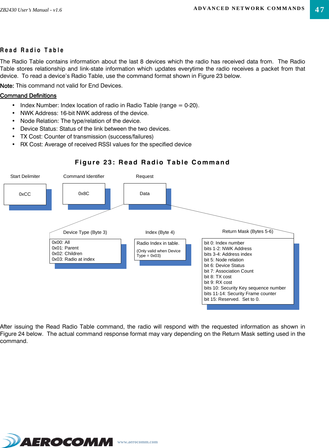
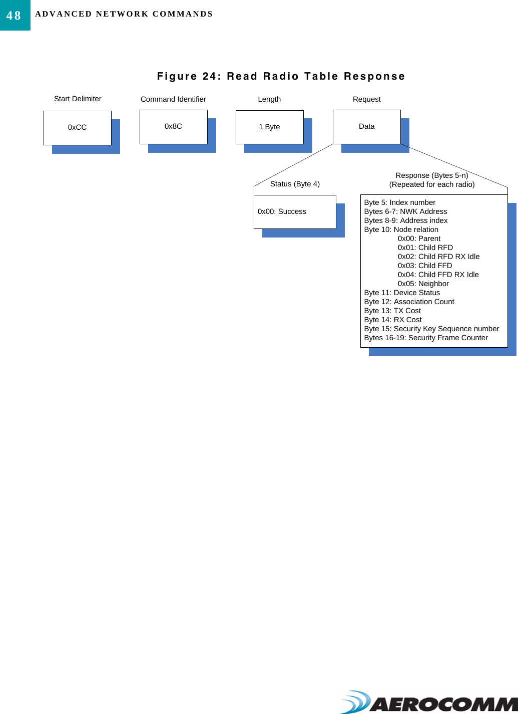
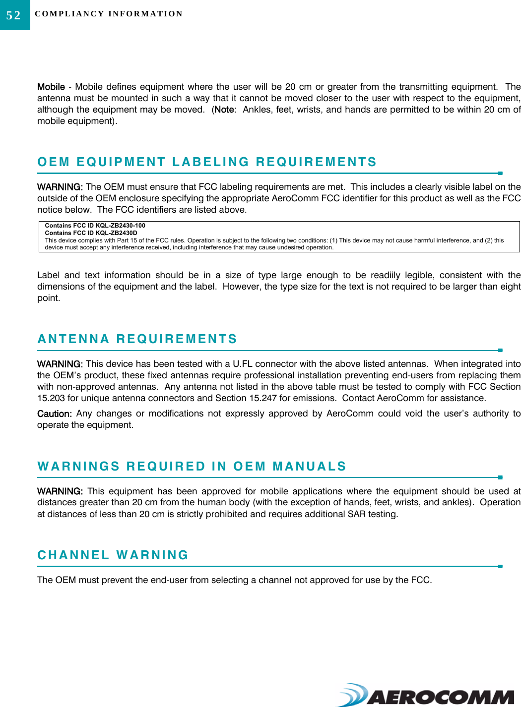
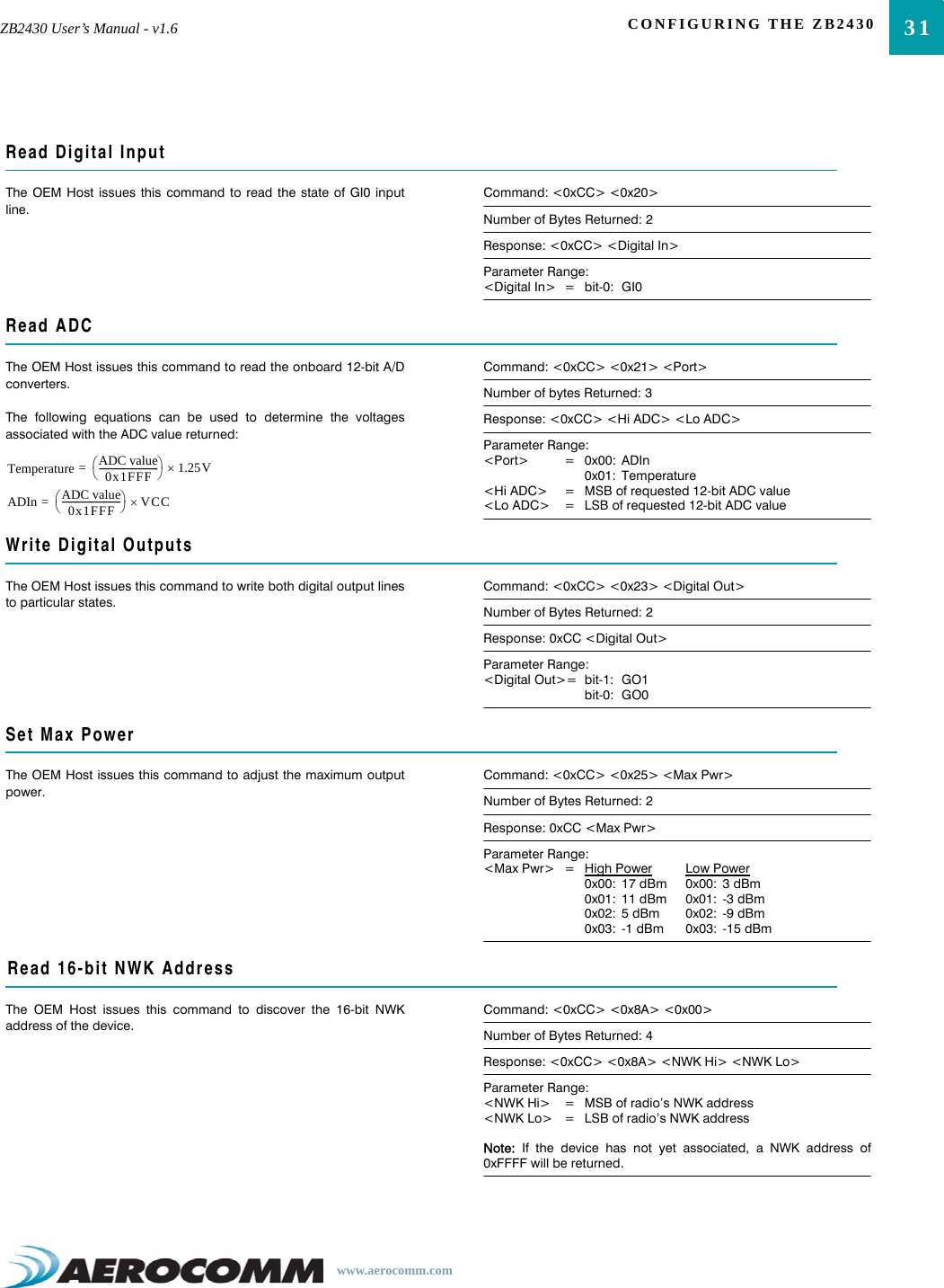
![27ZB2430 User’s Manual - v1.6 CONFIGURING THE ZB2430www.aerocomm.comAT COMMANDSThe AT Command mode implemented in the ZB2430 creates a virtual version of the Command/Data pin. The “EnterAT Command Mode” Command asserts this virtual pin Low (to signify Command Mode) and the “Exit AT CommandMode” Command asserts this virtual pin High (to signify Data). Once this pin has been asserted Low, all On-the-FlyCC Commands documented in the manual are supported.On-the-Fly Control CommandsThe ZB2430 transceiver contains static memory that holds many of the parameters that control the transceiveroperation. Using the “CC” command set allows many of these parameters to be changed during system operation.Because the memory these commands affect is static, when the transceiver is reset, these parameters will revert backto the settings stored in the EEPROM. While in CC Command mode using pin 15 (Command/Data), the RF interfaceof the transceiver is still active. Therefore, it can receive packets from remote transceivers while in CC Commandmode and forward these to the OEM Host. While in Command mode, the incoming RF interface of the transceiver is active and packets sent from othertransceivers will still be received; however no outgoing RF packets will be sent. The transceiver uses InterfaceTimeout/RF Packet Size to determine when a CC Command is complete. Therefore, there should be no delaybetween each character as it is sent from the OEM Host to the transceiver or the transceiver will not recognize thecommand.When an invalid command is sent, the radio discards the data and no response is sent to the OEM Host. Table 8below shows a quick summary of the basic configuration & diagnostic commands available on the ZB2430. Fordetailed command information, please refer to the command descriptions immedietly following the Quick ReferenceTable.Table 8: Command Quick ReferenceCommand Name Command (All bytes in Hex) Return (All bytes in Hex)Enter AT Command Mode <0x41> <0x54> <0x2B> <0x2B> <0x2B> <0x0D> <0xCC> <0x43> <0x4F> <0x4D>Exit AT Command Mode <0xCC> <0x41> <0x54> <0x4F> <0x0D> <0xCC> <0x44> <0x41> <0x54>Status Request <0xCC> <0x00> <0x00> <0xCC> <Firmware> <Status>Read Channel <0xCC> <0x02> <0xCC> <Channel> <Channel Mask [3-0]>Write Destination NWK Address<0xCC> <0x10> <0x00> <NWK Hi> <NWK Lo> <0xCC> <0x00> <NWK Hi> <NWK Lo>Read Destination NWK Address<0xCC> <0x11> <0xCC> <0x00> <NWK Hi> <NWK Lo>Auto Destination <0xCC> <0x15> <Data> <0xCC> <Data>Read API Control <0xCC> <0x16> <0xCC> <API Control>Write API Control <0xCC> <0x17> <API Control> <0xCC> <API Control>Read Digital Input <0xCC> <0x20> <0xCC> <Data>Read ADC <0xCC> <0x21> <Data> <0xCC> <ADC Hi> <ADC Lo>Write Digital Outputs <0xCC> <0x23> <Data> <0xCC> <Data>Set Power Control <0xCC> <0x25> <Power> <0xCC> <Power>Read NWK Address <0xCC> <0x8A> <0x00> <0xCC> <0x8A> <NWK Hi> <NWK Lo>](https://usermanual.wiki/Laird-Connectivity/ZB2430D/User-Guide-892780-Page-32.png)
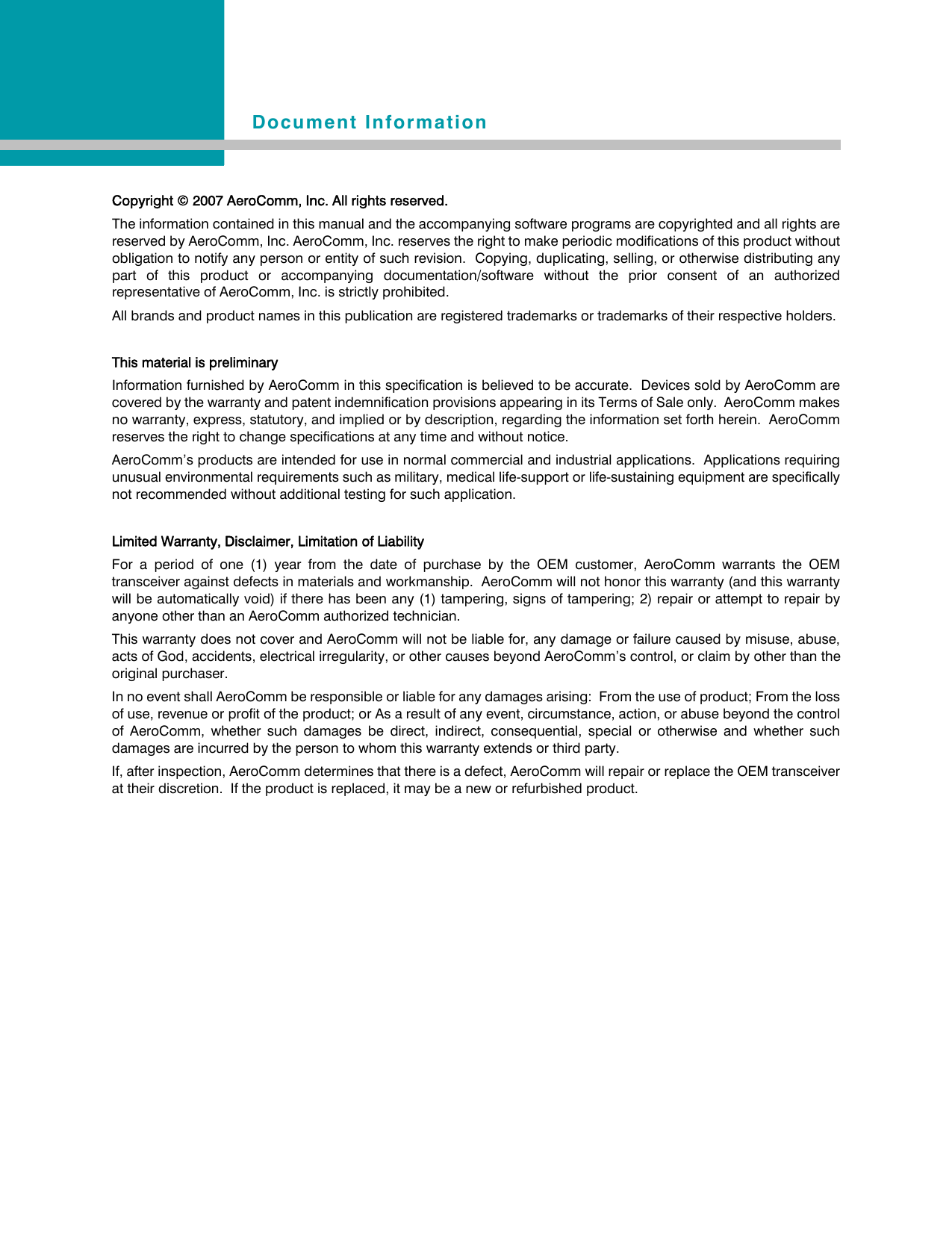
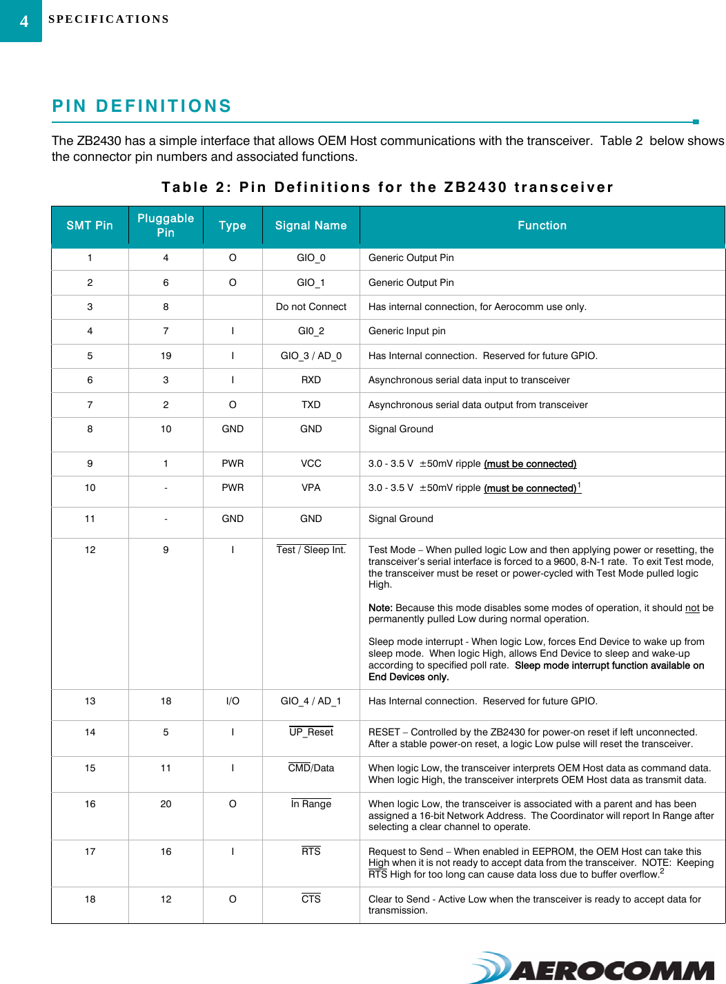
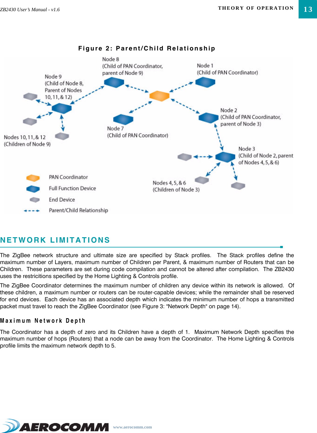
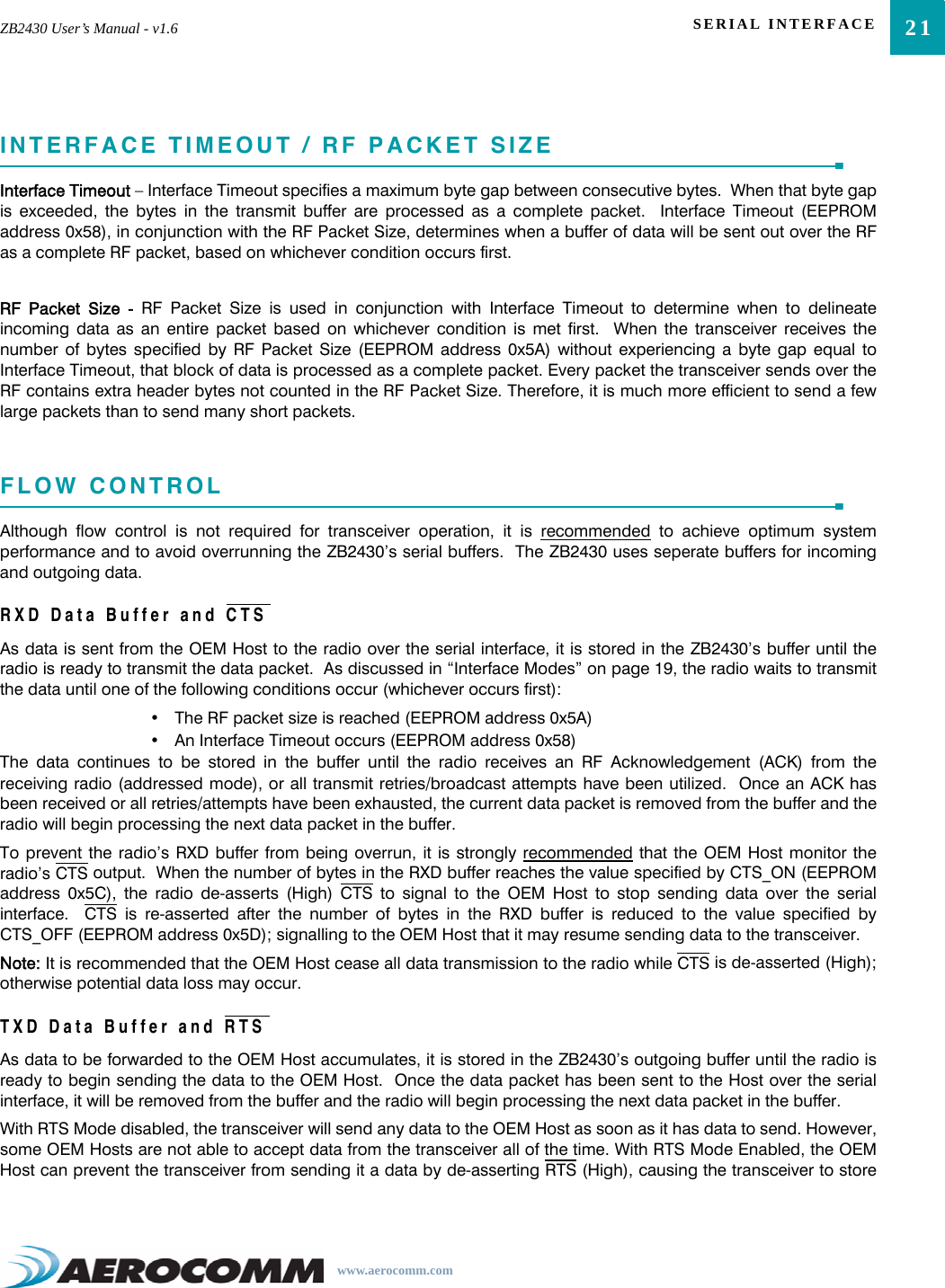
![CONFIGURING THE ZB243028Read Parent’s NWK Address <0xCC> <0x8A> <0x01> <0xCC> <NWK Hi> <NWK Lo>Discover NWK Address <0xCC> <0x8D> <00> <MAC [2-0]> <Data> <0xCC> <NWK Hi> <NWK Lo> <Data [n-0]>Discover IEEE Address <0xCC> <0x8E> <NWK Hi> <NWK Lo> <Data> <0xCC> <MAC [7-0]> <Data [n-0]>Read Temperature <0xCC> <0xA4> <0xCC> <Temperature [1-0]>EEPROM Byte Read <0xCC> <0xC0> <Start> <Length> <0xCC> <Start> <Length> <Data [n-0]>EEPROM Byte Write <0xCC> <0xC1> <Start> <Length> <Data> <Start> <Length> <Last byte written>Soft Reset <0xCC> <0xFF> NoneSoft Reset with NV reset <0xCC> <0xFF> <0xE3> NoneTable 8: Command Quick ReferenceCommand Name Command (All bytes in Hex) Return (All bytes in Hex)](https://usermanual.wiki/Laird-Connectivity/ZB2430D/User-Guide-892780-Page-33.png)
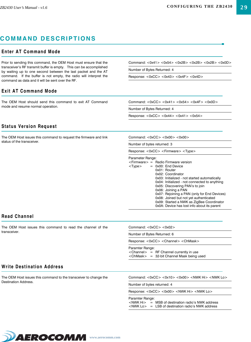
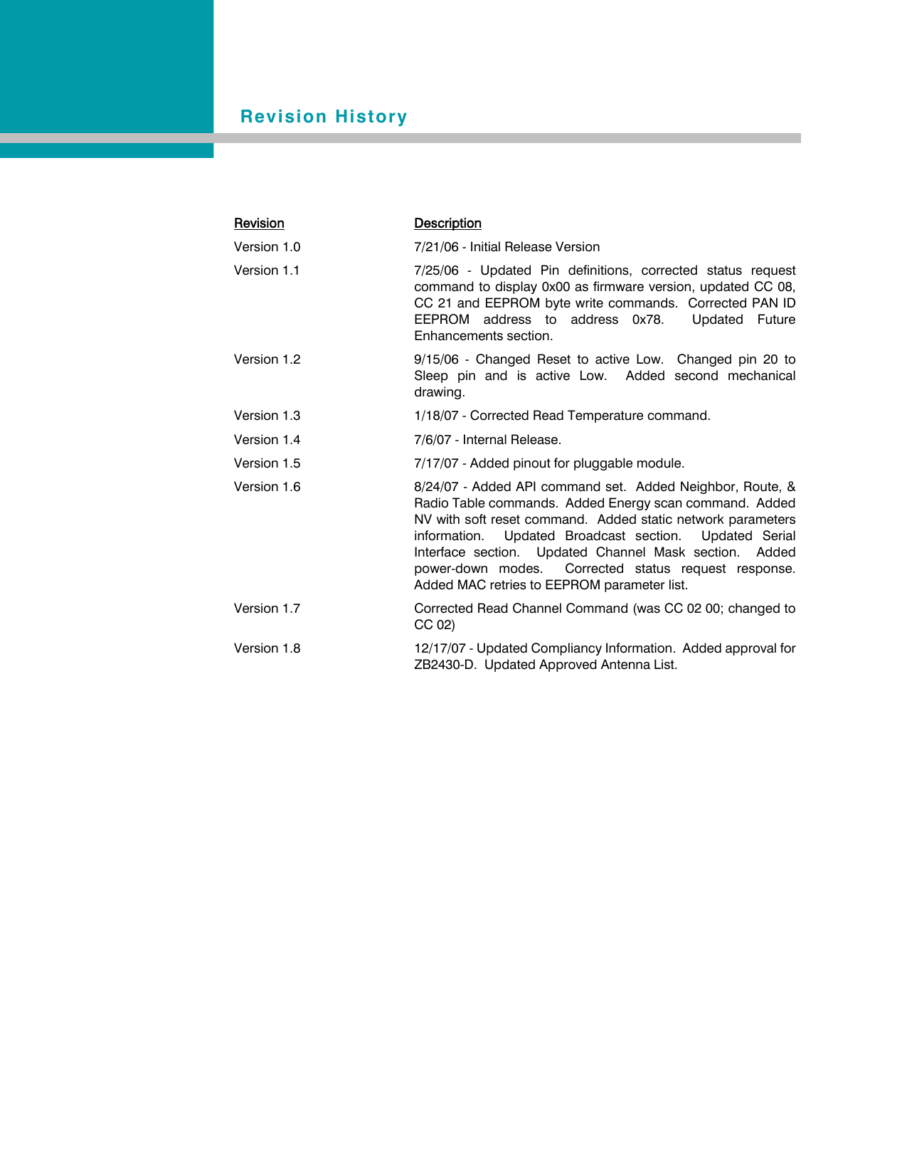
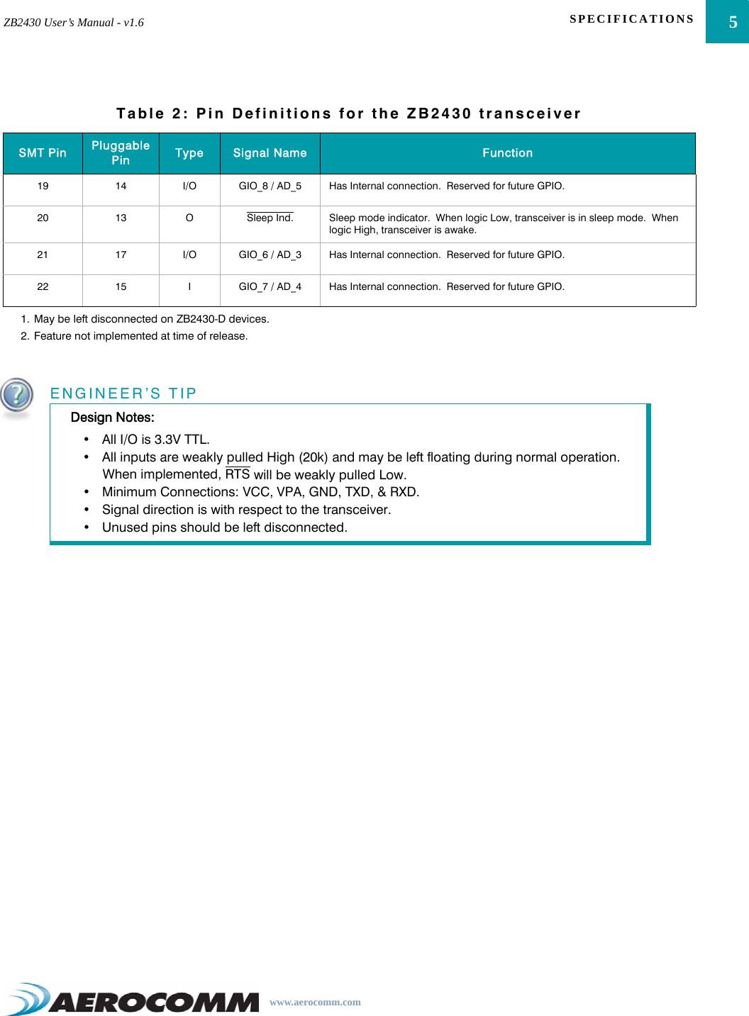
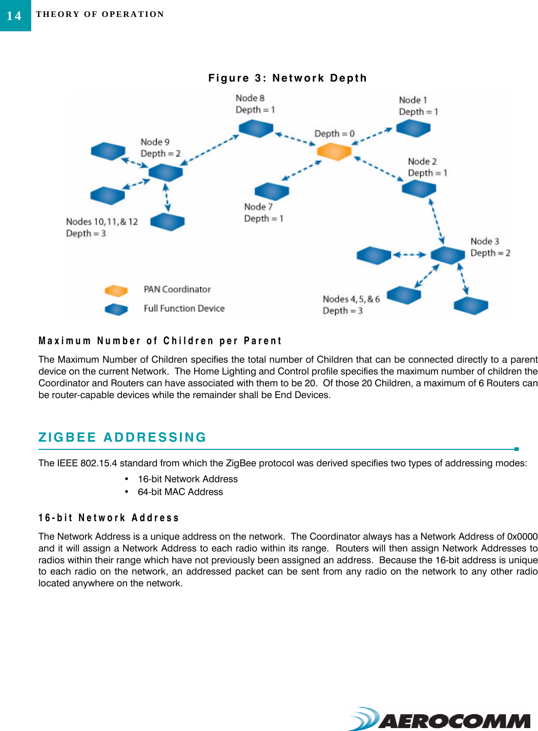
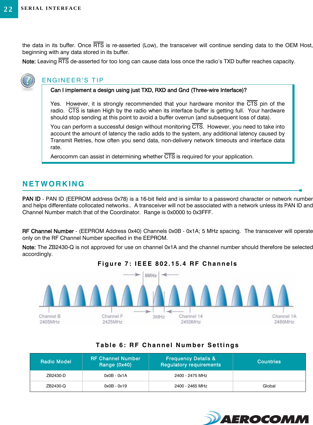
![CONFIGURING THE ZB243032Read 16-bit NWK Address of Parent DeviceThe OEM Host issues this command to discover the 16-bit NWKaddress of its’ Parent Device.Command: <0xCC> <0x8A> <0x01>Number of Bytes Returned: 4Response: <0xCC> <0x8A> <NWK Hi> <NWK Lo>Parameter Range:<NWK Hi> = MSB of Parent’s NWK address<NWK Lo> = LSB of Parent’s NWK addressNote: If the device has not yet associated, a NWK address of0xFFFF will be returned.Discover 16-bit NWK Address of Remote RadioThe OEM Host issues this command to discover the 16-bit NWKaddress of a remote radio.Note: This command is valid only for Coordinators and/or Routerdevices. This command will not issue a response if the requestedaddress is unable to be located in the network. A timeout of severalseconds should be assumed when using this command.Command: <0xCC> <0x8D> <IEEE [7-0]>Number of Bytes Returned: 3Response: <0xCC> <NWK Hi> <NWK Lo> Parameter Range:<IEEE> = 64-bit IEEE Address of remote radio<NWK Hi> = MSB of remote radio’s NWK address<NWK Lo> = LSB of remote radio’s NWK addressDiscover 16-bit NWK Address & Children of Remote RadioThe OEM Host issues this command to discover the 16-bit NWKaddress of a remote radio as well as report a list of that device’sChildren.Note: This command is valid only for Coordinators and/or Routerdevices. This command will not issue a response if the requestedaddress is unable to be located in the network. A timeout of severalseconds should be assumed when using this command.Command: <0xCC> <0x8D> <IEEE [7-0]> <0x01>Number of Bytes Returned: 10+Response: <0xCC> <NWK Hi> <NWK Lo> <Length> <List>Parameter Range:<IEEE> = 64-bit IEEE Address of remote radio<NWK Hi> = MSB of remote radio’s NWK address<NWK Lo> = LSB of remote radio’s NWK address<Length> = Length of data to follow<List> = List of remote radio’s associated devices [<Index n> <NWK Hi n> <NWK Lo n>]Discover IEEE Address of Remote RadioThe OEM Host issues this command to discover the 64-bit IEEEaddress of a remote radio.Note: This command is valid only for Coordinators and/or Routerdevices. This command will not issue a response if the requestedaddress is unable to be located in the network. A timeout of severalseconds should be assumed when using this command.Command: <0xCC> <0x8E> <0x00> <NWK Hi> <NWK Lo>Number of Bytes Returned: 9Response: <0xCC> <IEEE [7-0]> Parameter Range:<NWK Hi> = MSB of remote radio’s NWK address<NWK Lo> = LSB of remote radio’s NWK address<IEEE> = 64-bit IEEE Address of remote radio](https://usermanual.wiki/Laird-Connectivity/ZB2430D/User-Guide-892780-Page-37.png)
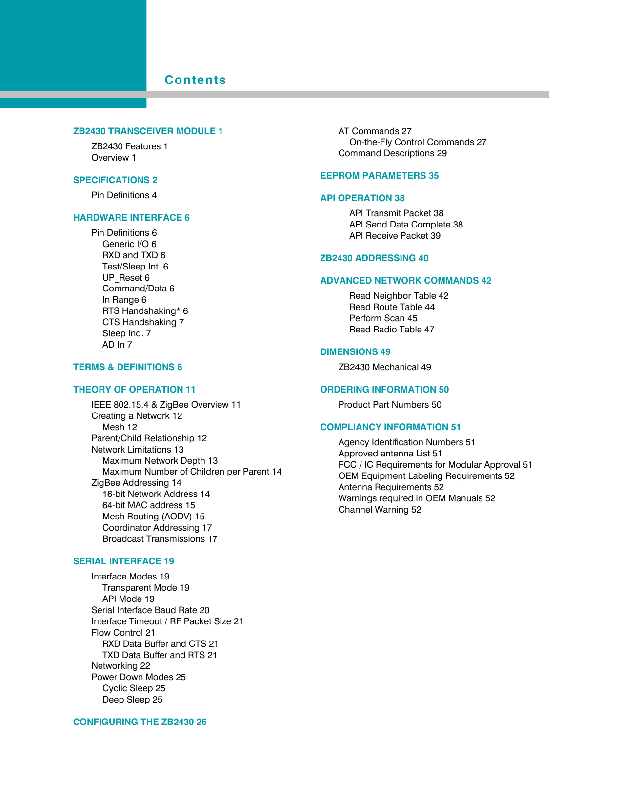
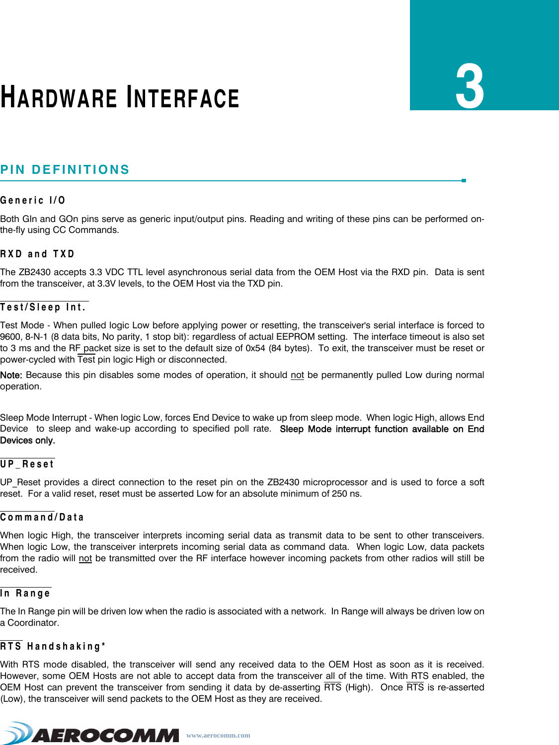
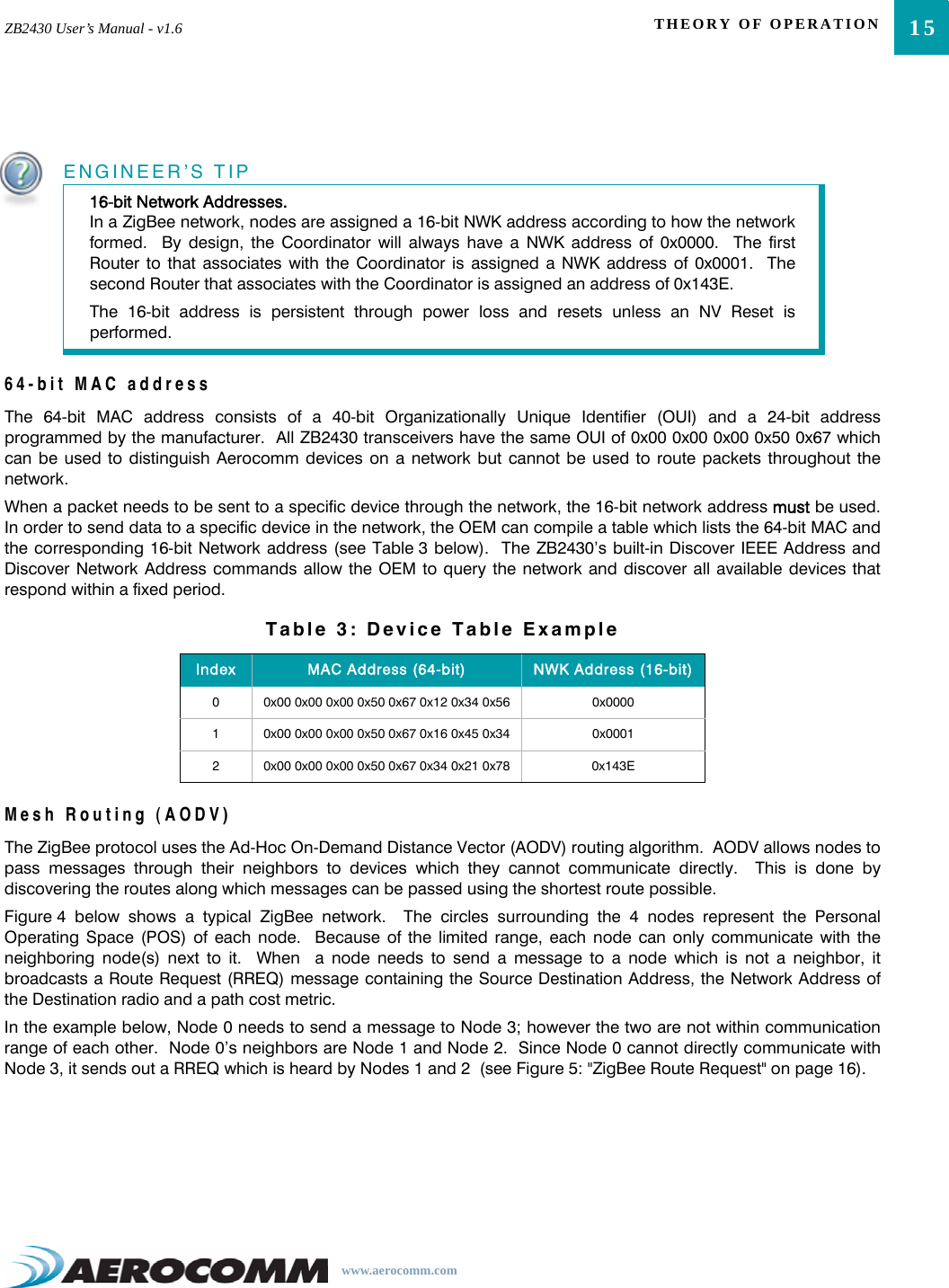
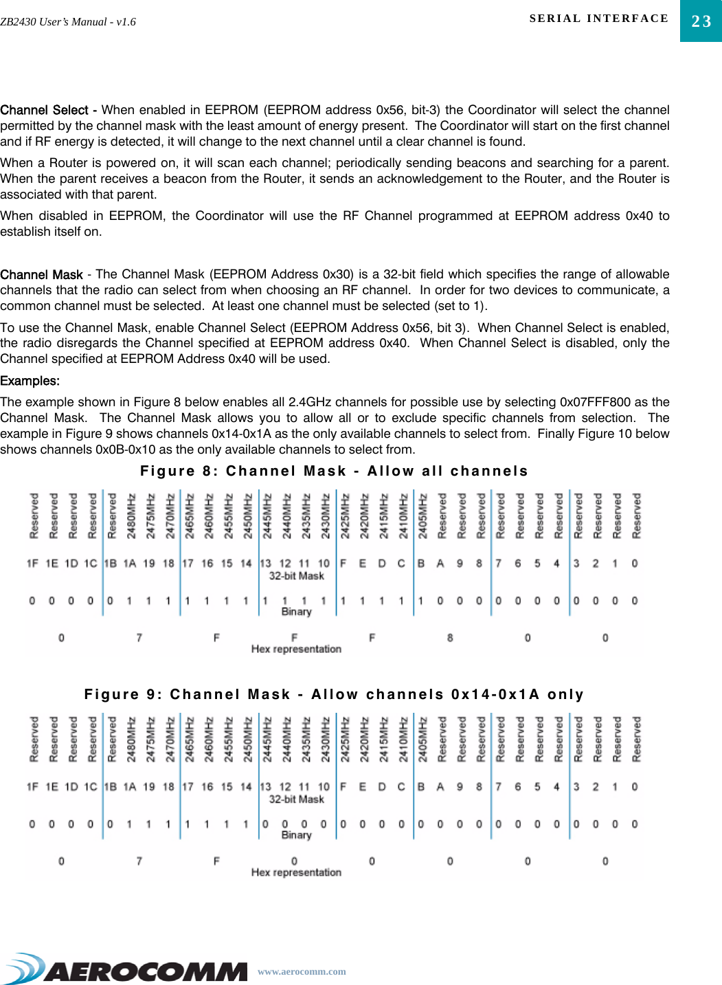
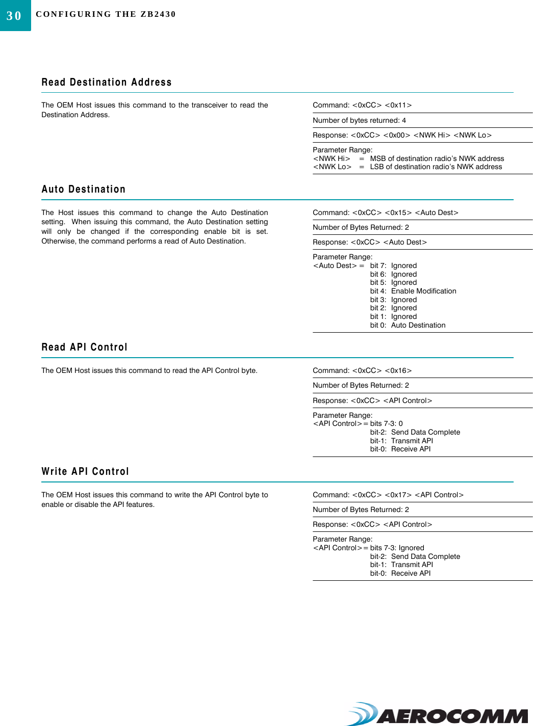
![33ZB2430 User’s Manual - v1.6 CONFIGURING THE ZB2430www.aerocomm.comDiscover IEEE Address & Children of Remote RadioThe OEM Host issues this command to discover the 64-bit IEEEaddress of a remote radio as well as report a list of that device’sChildren.Note: This command is valid only for Coordinators and/or Routerdevices. This command will not issue a response if the requestedaddress is unable to be located in the network. A timeout of severalseconds should be assumed when using this command.Command: <0xCC> <0x8E> <0x00> <NWK Hi> <NWK Lo><0x01>Number of Bytes Returned: 10+Response: <0xCC> <IEEE [7-0]> <Length> <List>Parameter Range:<NWK Hi> = MSB of remote radio’s NWK address<NWK Lo> = LSB of remote radio’s NWK address<IEEE> = 64-bit IEEE Address of remote radio<Length> = Length of data to follow<List> = List of remote radio’s associated devices [<Index n> <NWK Hi n> <NWK Lo n>]Read TemperatureThe OEM Host issues this command to read the onboardtemperature sensor.Note: The temperature sensor is uncalibrated and has a tolerance of+/- 3C. For calibration instructions, contact Aerocomm’s technicalsupport.Command: <0xCC> <0xA4>Number of bytes returned: 3Response: 0xCC <+/-> <Temp.>Parameter Range:<+/-> = 0x2B: +0x2D: -<Temp.> = Temperature (Celsius)EEPROM Byte ReadUpon receiving this command, a transceiver will respond with thedesired data from the addresses requested by the OEM Host.Command: <0xCC> <0xC0> <Start> <Length>Number of Bytes Returned: 4+Response: <0xCC> <Start> <Length> <Data>Parameter Range:<Start> = EEPROM address to begin reading at<Length> = Length of data to be read<Data> = Requested dataEEPROM Byte WriteUpon receiving this command, a transceiver will write the data byteto the specified address but will not echo it back to the OEM Hostuntil the EEPROM write cycle is complete.Note: The maximum length of data that can be written in a singlewrite process is 0x50. If writing the entire 256-byte EEPROM, it isconvenient to perform 64 byte (0x40) writes.Command: <0xCC> <0xC1> <Start> <Length> <Data>Number of Bytes Returned: 3Response: <Start> <Length> <Last byte>Parameter Range:<Start> = EEPROM address to begin writing at<Length> = Length of data to be written (Max = 0x50)<Data> = Data to be written<Last byte> = Value of last byte writtenResetThe OEM Host issues this command to perform a soft reset of thetransceiver. Any transceiver settings modified by CC commands willrevert to the values stored in the EEPROM.Command: <0xCC> <0xFF>Number of Bytes Returned: NoneResponse: None](https://usermanual.wiki/Laird-Connectivity/ZB2430D/User-Guide-892780-Page-38.png)