Lakeshore Learning Materials 642 Users Manual 642_v1.3
2015-02-09
: Lakeshore-Learning-Materials Lakeshore-Learning-Materials-642-Users-Manual-569643 lakeshore-learning-materials-642-users-manual-569643 lakeshore-learning-materials pdf
Open the PDF directly: View PDF ![]() .
.
Page Count: 122 [warning: Documents this large are best viewed by clicking the View PDF Link!]
Revision 1.3 P/N 119-042 9 January 2008
Lake Shore Cryotronics, Inc.
575 McCorkle Blvd.
Westerville, Ohio 43082-8888 USA
E-mail Addresses:
sales@lakeshore.com
service@lakeshore.com
Visit Our Website At:
www.lakeshore.com
Fax: (614) 891-1392
Telephone: (614) 891-2243
Methods and apparatus disclosed and described herein have been developed solely on company funds of Lake Shore Cryotronics, Inc. No government
or other contractual support or relationship whatsoever has existed which in any way affects or mitigates proprietary rights of Lake Shore Cryotronics,
Inc. in these developments. Methods and apparatus disclosed herein may be subject to U.S. Patents existing or applied for. Lake Shore Cryotronics,
Inc. reserves the right to add, improve, modify, or withdraw functions, design modifications, or products at any time without notice. Lake Shore shall
not be liable for errors contained herein or for incidental or consequential damages in connection with furnishing, performance, or use of this material.
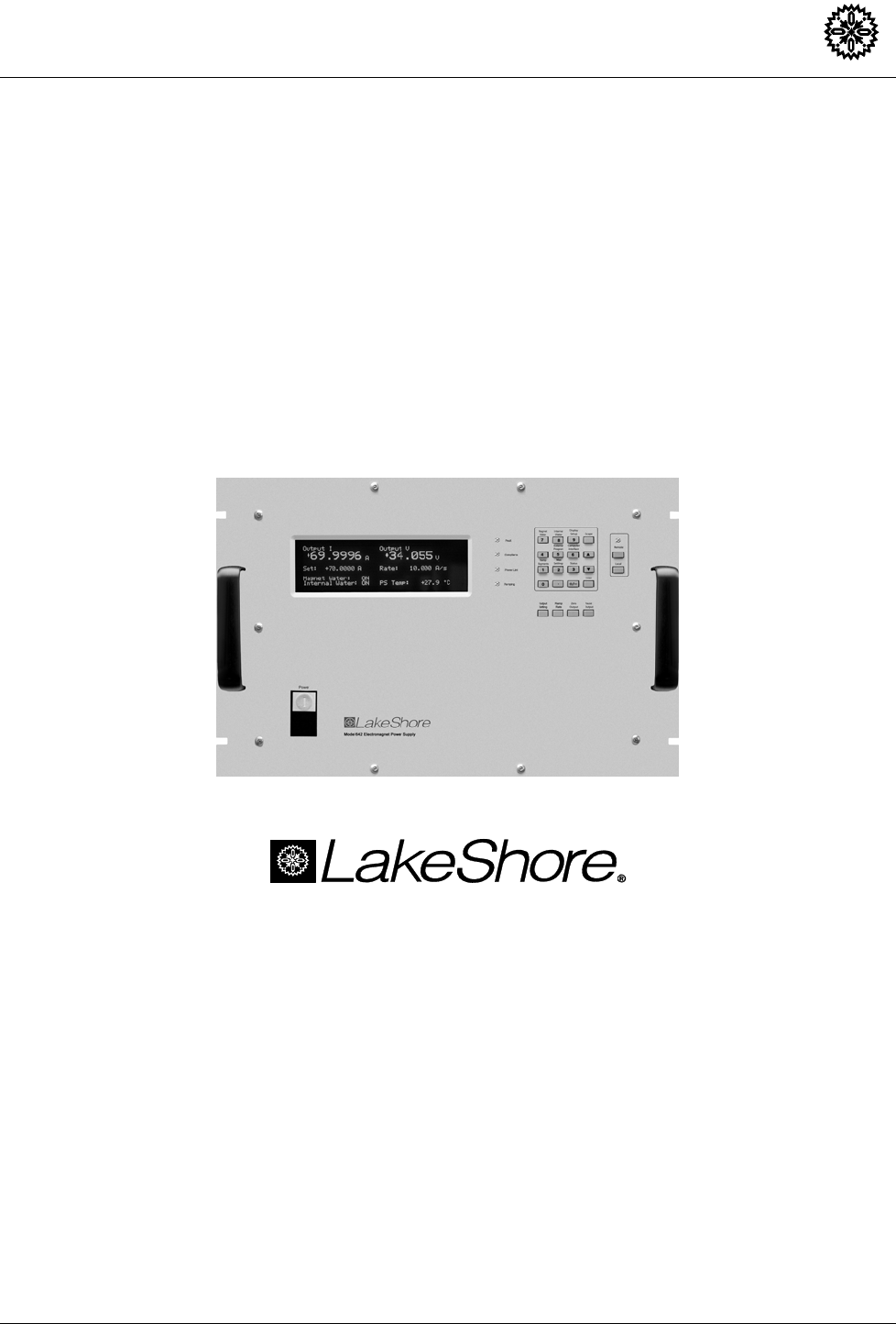
User’s Manual
Model 642
Electromagnet
Power Su
pp
l
y

Lake Shore Model 642 Electromagnet Power Supply User’s Manual
ii
LIMITED WARRANTY STATEMENT
WARRANTY PERIOD: ONE (1) YEAR
1. Lake Shore warrants that this Lake Shore product (the “Product”) will
be free from defects in materials and workmanship for the Warranty
Period specified above (the “Warranty Period”). If Lake Shore receives
notice of any such defects during the Warranty Period and the Product
is shipped freight prepaid, Lake Shore will, at its option, either repair
or replace the Product if it is so defective without charge to the owner
for parts, service labor or associated customary return shipping cost.
Any such replacement for the Product may be either new or equivalent
in performance to new. Replacement or repaired parts will be
warranted for only the unexpired portion of the original warranty or 90
days (whichever is greater).
2. Lake Shore warrants the Product only if it has been sold by an
authorized Lake Shore employee, sales representative, dealer or
original equipment manufacturer (OEM).
3. The Product may contain remanufactured parts equivalent to new in
performance or may have been subject to incidental use.
4. The Warranty Period begins on the date of delivery of the Product or
later on the date of installation of the Product if the Product is installed
by Lake Shore, provided that if you schedule or delay the Lake Shore
installation for more than 30 days after delivery the Warranty Period
begins on the 31st day after delivery.
5. This limited warranty does not apply to defects in the Product resulting
from (a) improper or inadequate maintenance, repair or calibration, (b)
fuses, software and non-rechargeable batteries, (c) software,
interfacing, parts or other supplies not furnished by Lake Shore, (d)
unauthorized modification or misuse, (e) operation outside of the
published specifications or (f) improper site preparation or
maintenance.
6. TO THE EXTENT ALLOWED BY APPLICABLE LAW, THE
ABOVE WARRANTIES ARE EXCLUSIVE AND NO OTHER
WARRANTY OR CONDITION, WHETHER WRITTEN OR ORAL,
IS EXPRESSED OR IMPLIED. LAKE SHORE SPECIFICALLY
DISCLAIMS ANY IMPLIED WARRANTIES OR CONDITIONS OF
MERCHANTABILITY, SATISFACTORY QUALITY AND/OR
FITNESS FOR A PARTICULAR PURPOSE WITH RESPECT TO
THE PRODUCT. Some countries, states or provinces do not allow
limitations on an implied warranty, so the above limitation or
exclusion might not apply to you. This warranty gives you specific
legal rights and you might also have other rights that vary from
country to country, state to state or province to province.
7. TO THE EXTENT ALLOWED BY APPLICABLE LAW, THE
REMEDIES IN THIS WARRANTY STATEMENT ARE YOUR
SOLE AND EXCLUSIVE REMEDIES.
8. EXCEPT TO THE EXTENT PROHIBITED BY APPLICABLE
LAW, IN NO EVENT WILL LAKE SHORE OR ANY OF ITS
SUBSIDIARIES, AFFILIATES OR SUPPLIERS BE LIABLE FOR
DIRECT, SPECIAL, INCIDENTAL, CONSEQUENTIAL OR
OTHER DAMAGES (INCLUDING LOST PROFIT, LOST DATA
OR DOWNTIME COSTS) ARISING OUT OF THE USE,
INABILITY TO USE OR RESULT OF USE OF THE PRODUCT,
WHETHER BASED IN WARRANTY, CONTRACT, TORT OR
OTHER LEGAL THEORY, AND WHETHER OR NOT LAKE
SHORE HAS BEEN ADVISED OF THE POSSIBILITY OF SUCH
DAMAGES. Your use of the Product is entirely at your own risk.
Some countries, states and provinces do not allow the exclusion of
liability for incidental or consequential damages, so the above
limitation may not apply to you.
LIMITED WARRANTY STATEMENT (Continued)
9. EXCEPT TO THE EXTENT ALLOWED BY APPLICABLE LAW,
THE TERMS OF THIS LIMITED WARRANTY STATEMENT DO
NOT EXCLUDE, RESTRICT OR MODIFY, AND ARE IN
ADDITION TO, THE MANDATORY STATUTORY RIGHTS
APPLICABLE TO THE SALE OF THE PRODUCT TO YOU.
CERTIFICATION
Lake Shore certifies that this product has been inspected and tested in
accordance with its published specifications and that this product met its
published specifications at the time of shipment. The accuracy and
calibration of this product at the time of shipment are traceable to the
United States National Institute of Standards and Technology (NIST);
formerly known as the National Bureau of Standards (NBS).
FIRMWARE LIMITATIONS
Lake Shore has worked to ensure that the Model 642 firmware is as free
of errors as possible, and that the results you obtain from the instrument
are accurate and reliable. However, as with any computer-based software,
the possibility of errors exists.
In any important research, as when using any laboratory equipment,
results should be carefully examined and rechecked before final
conclusions are drawn. Neither Lake Shore nor anyone else involved in
the creation or production of this firmware can pay for loss of time,
inconvenience, loss of use of the product, or property damage caused by
this product or its failure to work, or any other incidental or consequential
damages. Use of our product implies that you understand the Lake Shore
license agreement and statement of limited warranty.
FIRMWARE LICENSE AGREEMENT
The firmware in this instrument is protected by United States copyright
law and international treaty provisions. To maintain the warranty, the
code contained in the firmware must not be modified. Any changes made
to the code is at the user’s risk. Lake Shore will assume no responsibility
for damage or errors incurred as result of any changes made to the
firmware.
Under the terms of this agreement you may only use the Model 642
firmware as physically installed in the instrument. Archival copies are
strictly forbidden. You may not decompile, disassemble, or reverse
engineer the firmware. If you suspect there are problems with the
firmware, return the instrument to Lake Shore for repair under the terms
of the Limited Warranty specified above. Any unauthorized duplication
or use of the Model 642 firmware in whole or in part, in print, or in any
other storage and retrieval system is forbidden.
TRADEMARK ACKNOWLEDGMENT
Many manufacturers and sellers claim designations used to distinguish
their products as trademarks. Where those designations appear in this
manual and Lake Shore was aware of a trademark claim, they appear with
initial capital letters and the ™ or ® symbol.
CalCurve™, Cernox™, Duo-Twist™, Quad-Lead™, Quad-Twist™,
Rox™, and SoftCal™ are trademarks of Lake Shore Cryotronics, Inc.
MS-DOS® and Windows® are trademarks of Microsoft Corp.
NI-488.2™ is a trademark of National Instruments.
PC, XT, AT, and PS-2 are trademarks of IBM.
Copyright © 2006 by Lake Shore Cryotronics, Inc. All rights reserved. No portion of this manual may be reproduced,
stored in a retrieval system, or transmitted, in any form or by any means, electronic, mechanical, photocopying,
recording, or otherwise, without the express written permission of Lake Shore.
Lake Shore Model 642 Electromagnet Power Supply User’s Manual
iii

Lake Shore Model 642 Electromagnet Power Supply User’s Manual
iv
This Page Intentionally Left Blank

Lake Shore Model 642 Electromagnet Power Supply User’s Manual
Table of Contents v
TABLE OF CONTENTS
Chapter/Section Title Page
1 INTRODUCTION .................................................................................................................................................... 1-1
1.0 GENERAL............................................................................................................................................. 1-1
1.1 DESCRIPTION...................................................................................................................................... 1-1
1.2 SPECIFICATIONS ................................................................................................................................ 1-3
1.3 SAFETY SUMMARY............................................................................................................................. 1-7
1.4 SAFETY SYMBOLS.............................................................................................................................. 1-9
2 MAGNET SYSTEM DESIGN, INSTALLATION, AND OPERATION...................................................................... 2-1
2.0 GENERAL............................................................................................................................................. 2-1
2.1 INTRODUCTION................................................................................................................................... 2-1
2.2 MAGNET CONSTRUCTION................................................................................................................. 2-2
2.3 CONNECTING THE MAGNET.............................................................................................................. 2-2
2.3.1 Water Hose Connection .................................................................................................................... 2-2
2.3.2 Magnet Coil Wiring ............................................................................................................................ 2-2
2.3.3 Temperature Switches and Flow Switches........................................................................................ 2-4
2.3.4 Cooling Water and Water Valve ........................................................................................................ 2-4
2.3.5 Grounding.......................................................................................................................................... 2-4
2.3.6 Final Check-Out................................................................................................................................. 2-5
2.4 ELECTROMAGNET OPERATION........................................................................................................ 2-5
2.4.1 Air Gap and Pole Caps...................................................................................................................... 2-5
2.4.2 Maximum Power and Current............................................................................................................ 2-5
2.4.3 Operation Under Field Control........................................................................................................... 2-7
2.4.4 Avoiding Cooling Water Condensation.............................................................................................. 2-8
3 INSTALLATION...................................................................................................................................................... 3-1
3.0 GENERAL............................................................................................................................................. 3-1
3.1 INSPECTION AND UNPACKING ......................................................................................................... 3-1
3.1.1 Moving and Handling ............................................................................................................................ 3-1
3.2 REAR PANEL DEFINITION.................................................................................................................. 3-2
3.3 POWER WIRING AND SET-UP............................................................................................................ 3-3
3.3.1 Line Voltage Selection....................................................................................................................... 3-3
3.3.2 Circuit Breaker Setting....................................................................................................................... 3-4
3.3.3 Start-Up Fuses .................................................................................................................................. 3-5
3.3.4 Cable Entry........................................................................................................................................ 3-5
3.3.5 Power Input Terminals....................................................................................................................... 3-5
3.3.6 Wiring Cover...................................................................................................................................... 3-6
3.3.7 Mains Wiring...................................................................................................................................... 3-7
3.4 MAGNET CONNECTOR....................................................................................................................... 3-7
3.5 AUXILIARY CONNECTOR ................................................................................................................... 3-7
3.6 POWER SUPPLY CONNECTOR ......................................................................................................... 3-8
3.7 COOLING WATER................................................................................................................................ 3-8
3.8 MAGNET CABLE CONNECTIONS....................................................................................................... 3-9
3.9 ANALOG INPUT/OUTPUT CONNECTIONS ...................................................................................... 3-11
3.9.1 External Current Programming........................................................................................................ 3-11
3.9.2 Output Current and Voltage Monitors .............................................................................................. 3-11
3.10 COMPUTER INTERFACE .................................................................................................................. 3-11
3.10.1 RS-232C Interface Connection........................................................................................................ 3-11
3.10.2 IEEE-488 Interface Connection ....................................................................................................... 3-11
3.11 CHASSIS CONNECTION ................................................................................................................... 3-11
3.12 DETACHABLE HANDLES .................................................................................................................. 3-12
3.13 RACK MOUNTING.............................................................................................................................. 3-12

Lake Shore Model 642 Electromagnet Power Supply User’s Manual
vi Table of Contents
TABLE OF CONTENTS (Continued)
Chapter/Section Title Page
4 OPERATION...........................................................................................................................................................4-1
4.0 GENERAL.............................................................................................................................................4-1
4.1 TURNING POWER ON......................................................................................................................... 4-1
4.2 DISPLAY DEFINITION..........................................................................................................................4-2
4.3 LED ANNUNCIATORS.......................................................................................................................... 4-2
4.3.1 Fault LED...........................................................................................................................................4-2
4.3.2 Compliance LED................................................................................................................................4-2
4.3.3 Power Limit LED................................................................................................................................ 4-2
4.3.4 Ramping LED ....................................................................................................................................4-2
4.3.5 Remote LED......................................................................................................................................4-2
4.4 KEYPAD DEFINITION .......................................................................................................................... 4-3
4.4.1 General Keypad Operation................................................................................................................ 4-4
4.5 DISPLAY SETUP ..................................................................................................................................4-4
4.6 SETTING OUTPUT CURRENT ............................................................................................................4-4
4.7 CURRENT RAMP RATE.......................................................................................................................4-5
4.8 RAMP SEGMENTS............................................................................................................................... 4-5
4.9 PAUSE RAMP.......................................................................................................................................4-6
4.10 ZERO OUTPUT ....................................................................................................................................4-6
4.11 MAXIMUM SETTING LIMITS................................................................................................................4-7
4.11.1 Maximum Output Current ..................................................................................................................4-7
4.11.2 Maximum Current Ramp Rate ...........................................................................................................4-7
4.12 MAGNET WATER.................................................................................................................................4-8
4.13 INTERNAL WATER...............................................................................................................................4-8
4.14 ERROR STATUS DISPLAY..................................................................................................................4-8
4.15 EXTERNAL CURRENT PROGRAMMING ............................................................................................ 4-9
4.16 LOCKING THE KEYPAD ......................................................................................................................4-9
4.17 COMPUTER INTERFACE .................................................................................................................. 4-10
4.17.1 Changing Serial Baud Rate ............................................................................................................. 4-10
4.17.2 Changing IEEE-488 Interface parameters ....................................................................................... 4-11
4.18 DEFAULT PARAMETER VALUES...................................................................................................... 4-11
5 COMPUTER INTERFACE OPERATION................................................................................................................5-1
5.0 GENERAL.............................................................................................................................................5-1
5.1 IEEE-488 INTERFACE..........................................................................................................................5-1
5.1.1 Changing IEEE-488 Interface Parameters......................................................................................... 5-2
5.1.2 Remote/Local Operation.................................................................................................................... 5-2
5.1.3 IEEE-488 Command Structure .......................................................................................................... 5-2
5.1.3.1 Bus Control Commands .................................................................................................................5-3
5.1.3.2 Common Commands .....................................................................................................................5-3
5.1.3.3 Device Specific Commands ........................................................................................................... 5-3
5.1.3.4 Message Strings ............................................................................................................................5-3
5.1.4 Status System ...................................................................................................................................5-4
5.1.4.1 Overview........................................................................................................................................ 5-4
5.1.4.1.1 Condition Registers .................................................................................................................... 5-4
5.1.4.1.2 Event Registers ..........................................................................................................................5-4
5.1.4.1.3 Enable Registers ........................................................................................................................5-4
5.1.4.1.4 Status Byte Register...................................................................................................................5-4
5.1.4.1.5 Service Request Enable Register...............................................................................................5-4
5.1.4.1.6 Reading Registers...................................................................................................................... 5-7
5.1.4.1.7 Programming Registers..............................................................................................................5-7
5.1.4.1.8 Clearing Registers...................................................................................................................... 5-7

Lake Shore Model 642 Electromagnet Power Supply User’s Manual
Table of Contents vii
TABLE OF CONTENTS (Continued)
Chapter/Section Title Page
5.1.4.2 Status Register Sets ...................................................................................................................... 5-8
5.1.4.2.1 Standard Event Status Register ................................................................................................. 5-8
5.1.4.2.2 Operation Event Register Set..................................................................................................... 5-9
5.1.4.3 Error Status Register Sets ........................................................................................................... 5-10
5.1.4.3.1 Hardware Error Status Register Set ......................................................................................... 5-10
5.1.4.3.2 Operational Error Status Register Set ...................................................................................... 5-11
5.1.4.4 Status Byte and Service Request (SRQ) ..................................................................................... 5-12
5.1.4.4.1 Status Byte Register................................................................................................................. 5-12
5.1.4.4.2 Service Request Enable Register............................................................................................. 5-13
5.1.4.4.3 Using Service Request (SRQ) and Serial Poll.......................................................................... 5-13
5.1.4.4.4 Using Status Byte Query (*STB) .............................................................................................. 5-13
5.1.4.4.5 Using Message Available (MAV) Bit)........................................................................................ 5-13
5.1.4.4.6 Using Operation Complete (*OPC) and Operation Complete Query (*OPC?).......................... 5-14
5.1.5 IEEE-488 Interface Example Programs........................................................................................... 5-14
5.1.5.1 IEEE-488 Interface Board Installation for Visual Basic Program.................................................. 5-14
5.1.5.2 Visual Basic IEEE-488 Interface Program Setup ......................................................................... 5-16
5.1.5.3 Program Operation ...................................................................................................................... 5-20
5.1.6 Troubleshooting............................................................................................................................... 5-20
5.2 SERIAL INTERFACE OVERVIEW...................................................................................................... 5-21
5.2.1 Changing Baud Rate ....................................................................................................................... 5-21
5.2.2 Physical Connection........................................................................................................................ 5-21
5.2.3 Hardware Support ........................................................................................................................... 5-22
5.2.4 Character Format ............................................................................................................................ 5-22
5.2.5 Message Strings.............................................................................................................................. 5-22
5.2.6 Message Flow Control..................................................................................................................... 5-23
5.2.7 Serial Interface Example Programs................................................................................................. 5-23
5.2.7.1 Visual Basic Serial Interface Program Setup ............................................................................... 5-24
5.2.7.2 Program Operation ...................................................................................................................... 5-27
5.2.8 Troubleshooting............................................................................................................................... 5-27
5.3 COMMAND SUMMARY...................................................................................................................... 5-28
5.3.1 Interface Commands (Alphabetical Listing) ..................................................................................... 5-29
6 OPTIONS AND ACCESSORIES............................................................................................................................ 6-1
6.0 GENERAL............................................................................................................................................. 6-1
6.1 ACCESSORIES INCLUDED................................................................................................................. 6-1
6.2 ACCESSORIES AVAILABLE................................................................................................................ 6-1
7 SERVICE ................................................................................................................................................................ 7-1
7.0 GENERAL............................................................................................................................................. 7-1
7.1 CONTACTING LAKE SHORE CRYOTRONICS ................................................................................... 7-1
7.2 RETURNING PRODUCTS TO LAKE SHORE...................................................................................... 7-1
7.3 LINE VOLTAGE SELECTION............................................................................................................... 7-2
7.4 CIRCUIT BREAKER SETTING............................................................................................................. 7-3
7.5 POWER LINE FUSE REPLACEMENT .................................................................................................7-4
7.6 ERROR MESSAGES............................................................................................................................ 7-5
7.7 ELECTROSTATIC DISCHARGE .......................................................................................................... 7-6
7.7.1 Identification of Electrostatic Discharge Sensitive Components ........................................................ 7-6
7.7.2 Handling Electrostatic Discharge Sensitive Components .................................................................. 7-7
7.8 ENCLOSURE BOTTOM REMOVAL AND REPLACEMENT................................................................. 7-7
7.8.1 Removal ............................................................................................................................................ 7-7
7.8.2 Installation ......................................................................................................................................... 7-7

Lake Shore Model 642 Electromagnet Power Supply User’s Manual
viii Table of Contents
TABLE OF CONTENTS (Continued)
Chapter/Section Title Page
7.9 FIRMWARE REPLACEMENT............................................................................................................... 7-7
7.10 CONNECTOR AND CABLE DEFINITIONS ........................................................................................ 7-11
7.10.1 Analog I/O Connector ......................................................................................................................7-11
7.10.2 Magnet Connector ........................................................................................................................... 7-11
7.10.3 Auxiliary Connector..........................................................................................................................7-12
7.10.4 Power Supply Connector................................................................................................................. 7-13
7.10.5 RS-232C Serial Interface Connector ...............................................................................................7-13
7.10.6 Serial Interface Cable Wiring ...........................................................................................................7-14
7.10.7 IEEE-488 Parallel Interface Connector............................................................................................7-14
7.11 CALIBRATION .................................................................................................................................... 7-16
7.11.1 Calibration Interface.........................................................................................................................7-16
7.11.2 Calibration Equipment .....................................................................................................................7-17
7.11.3 Calibration Procedure...................................................................................................................... 7-17
7.11.3.1 Calibrate Current Output Zero...................................................................................................... 7-17
7.11.3.2 Calibrate Current Reading Zero ................................................................................................... 7-17
7.11.3.3 Calibrate Output Voltage Reading Zero ....................................................................................... 7-18
7.11.3.4 Calibrate External Program Voltage Reading Zero ...................................................................... 7-18
7.11.3.5 Calibrate Output Current Gain (Span).......................................................................................... 7-18
7.11.3.6 Calibrate Current Reading Gain...................................................................................................7-20
7.11.3.7 Calibrate Voltage Reading Gain...................................................................................................7-20
7.11.3.8 Calibrate External Current Programming Voltage Reading Gain ................................................. 7-21
7.11.4 Calibrate Specific Interface Commands........................................................................................... 7-21
APPENDIX A – GLOSSARY OF TERMINOLOGY....................................................................................................... A-1
APPENDIX B – UNITS FOR MAGNETIC PROPERTIES............................................................................................. B-1

Lake Shore Model 642 Electromagnet Power Supply User’s Manual
Table of Contents ix
LIST OF ILLUSTRATIONS
Figure No. Title Page
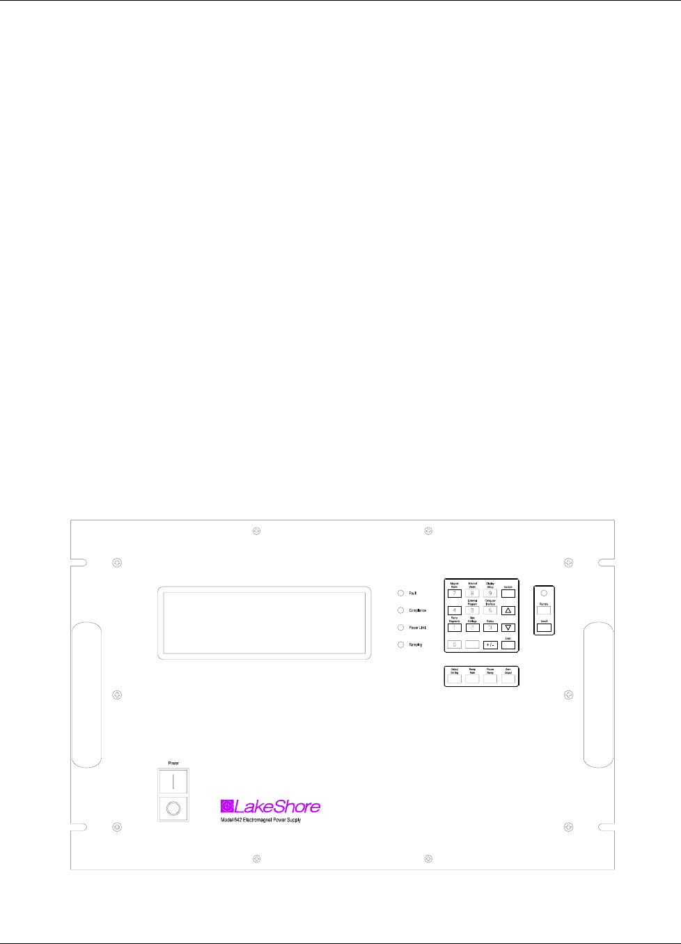
1-1 Model 642 Front Panel ............................................................................................................................. 1-2
2-1 A Typical Electromagnet........................................................................................................................... 2-1
2-2 Typical Magnet Water Hook-Up................................................................................................................ 2-2
2-3 Typical Magnet Coil Wiring Showing Series and Parallel Connections..................................................... 2-3
2-4 Typical Thermal Switch, Flow Switch and Valve Wiring............................................................................ 2-4
2-5 Typical Curves of Field vs. Current for Various Air Gaps and Pole Cap Sizes ......................................... 2-5
3-1 Model 642 Rear Panel.............................................................................................................................. 3-3
3-2 Voltage Change Detail.............................................................................................................................. 3-4
3-3 Circuit Breaker.......................................................................................................................................... 3-4
3-4 Fuses........................................................................................................................................................ 3-5
3-5 Typical Cable Entry with Bushing ............................................................................................................. 3-5
3-6 Typical Power Input Wiring....................................................................................................................... 3-6
3-7 Wiring Cover Installation........................................................................................................................... 3-6
3-8 Typical Magnet Connector Wiring............................................................................................................. 3-7
3-9 Typical Auxiliary Connector Wiring ........................................................................................................... 3-7
3-10 Typical Power Supply Connector Wiring................................................................................................... 3-8
3-11 Typical Water Hose Connection ............................................................................................................... 3-8
3-12 Water Valve Connection........................................................................................................................... 3-9
3-13 Output Cable Connection ....................................................................................................................... 3-10
3-14 Output Lug Cover Installation ................................................................................................................. 3-10
3-15 Analog Input/Output Connector .............................................................................................................. 3-11
3-16 Mounting Hole Pattern............................................................................................................................ 3-12
4-1 Model 642 Power Push Buttons ............................................................................................................... 4-1
4-2 Model 642 Keypad and LED Layout ......................................................................................................... 4-3
5-1 Model 642 Status System......................................................................................................................... 5-5
5-2 Standard Event Status Register................................................................................................................ 5-8
5-3 Operation Event Register ......................................................................................................................... 5-9
5-4 Hardware Error Status Register.............................................................................................................. 5-10
5-5 Operational Error Status Register........................................................................................................... 5-11
5-6 Status Byte Register and Service Request Enable Register .................................................................. 5-12
5-7 GPIB0 Setting Configuration................................................................................................................... 5-15
5-8 DEV 12 Device Template Configuration ................................................................................................. 5-15
5-9 Typical National Instruments GPIB Configuration from IBCONF.EXE.................................................... 5-19
7-1 Model 642 Rear Panel.............................................................................................................................. 7-2
7-2 Voltage Change Detail.............................................................................................................................. 7-3
7-3 Circuit Breaker.......................................................................................................................................... 7-4
7-4 Fuse Holder Detail.................................................................................................................................... 7-5
7-5 Board Locations........................................................................................................................................ 7-9
7-6 Digital Board Parts Locations ................................................................................................................. 7-10
7-7 Analog I/O Connector Details ................................................................................................................. 7-11
7-8 Magnet Connector Details ...................................................................................................................... 7-11
7-9 Auxiliary Connector Detail ...................................................................................................................... 7-12
7-10 Power Supply Connector Details ............................................................................................................ 7-13
7-11 RS-232C (DTE) Connector Details......................................................................................................... 7-13
7-12 IEEE-488 Connector Details................................................................................................................... 7-15

Lake Shore Model 642 Electromagnet Power Supply User’s Manual
x Table of Contents
LIST OF TABLES
Table No. Title Page
3-1 Rear Panel Connector Identification .........................................................................................................3-2
3-2 Voltage and Current Selection.................................................................................................................. 3-3
3-3 Current Capacity and Total Lead Lengths ................................................................................................ 3-9
4-1 Model 642 LED Descriptions .................................................................................................................... 4-2
4-2 Model 642 Key Descriptions ..................................................................................................................... 4-3
4-3 Default Parameter Values....................................................................................................................... 4-12
5-1 Binary Weighting of an 8-Bit Register .......................................................................................................5-7
5-2 Register Clear Methods ............................................................................................................................5-7
5-3 Programming Example to Generate an SRQ.......................................................................................... 5-13
5-4 IEEE-488 Interface Program Control Properties ..................................................................................... 5-17
5-5 Visual Basic IEEE-488 Interface Program ..............................................................................................5-18
5-6 Serial Interface Specifications................................................................................................................. 5-22
5-7 Serial Interface Program Control Properties ........................................................................................... 5-25
5-8 Visual Basic Serial Interface Program.....................................................................................................5-26
5-9 Command Summary............................................................................................................................... 5-29
7-1 Voltage and Current Selection.................................................................................................................. 7-3
7-2 Instrument Hardware Errors......................................................................................................................7-5
7-3 Operational Errors ....................................................................................................................................7-6
B-1 Conversion from CGS to SI Units .............................................................................................................B-1
B-2 Recommended SI Values for Physical Constants.....................................................................................B-2

Lake Shore Model 642 Electromagnet Power Supply User’s Manual
Introduction 1-1
CHAPTER 1
INTRODUCTION
1.0 GENERAL
This chapter provides an introduction to the Model 642 Electromagnet Power Supply. The Model 642 was designed and
manufactured in the United States of America by Lake Shore Cryotronics, Inc. The Model 642 features include the
following.
• True 4-quadrant (bipolar) 70 A, 35 V output
• 0.1 mA output setting resolution
• Linear regulation minimizes noise and ripple to 0.007% of maximum current into a 0.50 Ω load
• 1.0 mA stability per hour, 5 mA per 24 hour
• CE compliance to both the low voltage directive and the electromagnetic compatibility (EMC) directive
1.1 DESCRIPTION
The Model 642 Electromagnet Power Supply is the ideal supply for small- to medium-sized magnets used in
high-sensitivity materials research applications. The Model 642 is a practical alternative to both the larger one-size-fits-
all magnet supplies and the endless adaptations of generic power supplies. By optimizing output power, Lake Shore was
able to concentrate on the performance requirements of the most demanding magnet users. The resulting Model 642
provides high precision, low noise, safety, and convenience.
Precision in magnetic measurements is typically defined as smooth continuous operation with high setting resolution and
low drift. Achieving these goals while driving an inductive load requires unique solutions. The Model 642 delivers up to
70 A at a nominal voltage of 35 V, with the supply acting as either a source or a sink in true 4-quadrant operation. Its
current source output architecture with analog control enables both smooth operation and low drift. A careful blending of
analog and digital circuits provides high setting resolution of 0.1 mA and flexible output programming.
Lake Shore chose linear input and output power stages for the nominal 2450 W output of the Model 642. Linear
operation eliminates the radiated radio frequency (RF) noise associated with switching power supplies, allowing the
Model 642 to reduce the overall noise in its output and the noise radiated into surrounding electronics.
Safety should never be an afterthought when driving an inductive load. The Model 642 incorporates a variety of
hardware and firmware protection features to ensure the safety of the magnet and supply. For improved operator safety,
the power supply was also designed for compliance with the safety requirements of the CE mark, including both the low
voltage and the electromagnetic compatibility (EMC) directive.
Instrument users have come to rely on Lake Shore equipment for convenience and ease of use. The Model 642 includes
features such as built-in current and power limits, internal cooling-water and magnet-water control to minimize
condensation, current ramping and the capability to modulate the output current. Computer interfaces are also integrated
for automation of the magnet system. The Model 642 is truly an excellent one-box solution for controlling an
electromagnet.
Output Architecture
True 4-quadrant output capability of the Model 642 is ideal for the charge and discharge cycling of electromagnets for
both positive and negative fields. Tightly integrated analog control of the 4-quadrant output provides smooth current
change with very low overshoot on output change. The Model 642 has the ability to charge and discharge magnets up
to a 50 A per second rate into a nominal 0.5 Ω, 0.5 H load.
True 4-quadrant operation eliminates the need for external switching or operator intervention to reverse the current
polarity, significantly simplifying system operation. The transition through zero current is smooth and continuous,
allowing the user to readily control the magnetic field as polarity changes.
At static fields, output current drift is also kept low by careful attention in the analog control circuits and layout.
The high stability and low noise of the Model 642 provides a quiet and uniform magnetic field.
Lake Shore Model 642 Electromagnet Power Supply User’s Manual
1-2 Introduction
Output Architecture (Continued)
The Model 642 output architecture relies on low noise, linear input and output stages. The linear circuitry of the Model
642 permits operation with less electrical noise than switch-mode electromagnet power supplies. One key benefit of this
architecture is CE compliance to the electromagnetic compatibility (EMC) directive, including the radiated emissions
requirement.
Output Programming
The Model 642 output current is programmed internally via the keypad, externally by the computer interface, externally
by the analog programming input, or by the sum of the external and internal settings. For internal programming, the
Model 642 incorporates a proprietary digital-to-analog converter (DAC) that is monotonic over the entire output range
and provides a resolution of 0.1 mA.
The Model 642 generates extremely smooth and continuous ramps with virtually no overshoot. The digitally generated
constant current ramp rate is variable between 0.1 mA/s and 99.999 A/s. To ensure a smooth ramp rate, the power supply
updates the high-resolution DAC 23.7 times per second. A low-pass filter on the DAC output smoothes the transitions at
step changes during ramping.
Output Readings
The Model 642 provides high-resolution output readings. The output current reading has a resolution of 0.1 mA. The
output voltage reading reports the voltage at the output terminals with a resolution of 0.1 mV. All output readings can be
prominently displayed on the front panel and read over the computer interface.
Protection
The Model 642 continuously monitors the line voltage, load power, internal power, and load resistance as well as a
variety of other internal circuit parameters for signs of trouble. Some fault conditions result in a warning message while
others will provide a warning message and zero the output. When hazardous conditions exist, the Model 642 will shut
itself off.
NOTE: The Model 642 is equipped with a high-line lockout circuit which will prevent the unit from being turned
on if it is connected to a voltage source that is much higher than the voltage for which it is configured.
Figure 1-1. Model 642 Front Panel

Lake Shore Model 642 Electromagnet Power Supply User’s Manual
Introduction 1-3
Description (Continued)
Interfaces
The Model 642 includes IEEE-488 and RS-232C interfaces that provide access to operating data, stored parameters, and
remote control of all front panel operated functions. A keypad lock-out feature is provided to prohibit any changes made
from the front panel. The Model 642 can then be operated solely with the computer via the RS-232C or IEEE-488
interface.
The Model 642 provides two analog outputs to monitor the output current and voltage. Each output is a buffered,
differential, analog voltage representation of the signal being monitored. The current monitor has a sensitivity of
7 V = 70 A, while the voltage monitor has a sensitivity of 3.5 V = 35 V.
Display and Keypad
The Model 642 incorporates a large 8-line by 40-character vacuum fluorescent display. Output current and output
voltage readings are displayed simultaneously. Five LEDs on the front panel provide quick verification of instrument
status, including ramping, power limit, compliance, fault, and computer interface mode. Error conditions are indicated on
the main display along with an audible tone. Extended error descriptions are available in an error message screen by
pressing the Status key.
The keypad is arranged logically to separate the different functions of the instrument. The most common functions of the
power supply are accessed using a single key press. The keypad can be locked to either lock out all changes or to lock
out just the instrument setup parameters allowing the output of the power supply to be changed.
1.2 SPECIFICATIONS
Output
Type Bipolar, 4-quadrant, DC current source
Current generation Fully linear regulation with digital setting and analog control
Current range ±70 A
Compliance voltage (DC) ±35 V nominal
Power 2450 W nominal
Nominal load 0.5 Ω, 0.5 H
Maximum load resistance 0.6 Ω for ±70 A DC operation at +10% to –5% line voltage
Minimum load resistance 0.4 Ω for ±70 A at +5% to –10% line voltage
Load inductance range 0 H to 1 H
Current ripple 5 mA RMS (0.007%) at 70 A into nominal load
Current ripple frequency Dominated by the line frequency and its harmonics
Temperature coefficient ±15 ppm of full scale/°C
Line regulation ±60 ppm of full scale/10% line change
Stability (1 h) 1 mA/h (after warm-up)
>Stability (24 h) 5 mA/24 h (typical, dominated by temperature coefficient and line regulation)
Isolation Differential output is optically isolated from chassis to prevent ground loops
Slew rate 50 A/s into nominal load
650 A/s maximum into a resistive load
Compliance voltage (AC) ±43 V at +10% to –5% line
Settling time <1 s for 10% step to within 1 mA of output into nominal load
Modulation response ≤ 0.17 Hz at ±70 A sine wave into nominal load, <0.02% THD
≤ 10 Hz at ±10 A sine wave into nominal load, <0.10% THD
Attenuation –0.5 dB at 10 Hz
Protection Short circuit, line loss, low line voltage, high line voltage, output over voltage, output
over current, and over temperature
Connector Two lugs with 6.4 mm (0.25 in) holes for M6 or 0.25 in bolts

Lake Shore Model 642 Electromagnet Power Supply User’s Manual
1-4 Introduction
Specifications (Continued)
Output programming
Internal current setting
Resolution 0.1 mA (20 bit)
Settling time 600 ms for 1% step to within 1 mA (of internal setting)
Accuracy ±10 mA ±0.05% of setting
Operation Keypad, computer interface
Protection Programmable current setting limit
Internal current ramp
Ramp rate 0.1 mA/s to 99.999 A/s (compliance limited)
Update rate 23.7 increments/s
Ramp segments 5
Operation Keypad, computer interface
Protection Programmable ramp rate limit
External current programming
Sensitivity 10 V/70 A
Resolution Analog
Accuracy ±10 mA ±1% of setting
Input resistance 20 kΩ
Operation Voltage program through rear panel, can be summed with internal current setting
Limits Internally clamped at ±10.1 V and bandwidth limited at 40 Hz to protect output
Connector Shared 15-pin D-sub
Readings
Output current
Resolution 0.1 mA
Accuracy ±5 mA ±0.05% of rdg
Update rate 2.5 rdg/s display, 10 rdg/s interface
Output voltage (at supply terminals)
Resolution 1mV
Accuracy ±5 mV ±0.05% of rdg
Update rate 2.5 rdg/s display, 5 rdg/s interface
Front panel
Display type 8-line by 40-character graphic vacuum fluorescent display module
Display readings Output current, output voltage, and internal water temperature
Display settings Output current and ramp rate
Display annunciators Status and errors
LED annunciators Fault, Compliance, Power Limit, Ramping, Remote
Audible annunciator Errors and faults
Keypad type 26 full travel keys
Keypad functions Direct access to common operations, menu-driven setup
Power White flush ON and black extended OFF push buttons

Lake Shore Model 642 Electromagnet Power Supply User’s Manual
Introduction 1-5
Specifications (Continued)
Interface
IEEE-488.2 interface
Features SH1, AH1, T5, L4, SR1, RL1, PP0, DC1, DT0, C0, E1
Reading rate To 10 rdg/s
Software support National Instruments LabVIEW™ driver (consult Lake Shore for availability)
Serial interface
Electrical format RS-232C
Baud rates 9600, 19200, 38400, 57600
Reading rate To 10 rdg/s
Connector 9-pin D-sub (DTE)
Output current monitor
Sensitivity 7 V/70 A
Accuracy ±1% of full scale
Noise 1 mV RMS
Source impedance 20 Ω
Connector Shared 15-pin D-sub
Output voltage monitor
Sensitivity 3.5 V/35 V
Accuracy 1% of full scale
Noise 1 mV RMS
Source impedance 20 Ω
Connector Shared 15-pin D-sub
Power supply cooling water
Remote enable input TTL low or contact closure to enable output; jumper required if unused
Valve power output 24 VAC at 1 A maximum, automatic or manual control
Connector Shared 4-pin detachable terminal block
Flow switch and water valve optional
Magnet cooling water
Remote enable input TTL low or contact closure to enable output; jumper required if unused
Valve power output 24 VAC at 1 A maximum, automatic or manual control
Connector Shared 4-pin detachable terminal block
Flow switch, temperature switch, and water valve not included
Auxiliary
Emergency stop Requires 1 A, 24 VAC normally closed (NC) contact to enable power-up; jumper required if
unused
Fault output Relay with normally open (NO) or normally closed (NC) contact, 30 VDC at 1 A
Remote enable TTL low or contact closure to enable output, jumper required if unused
Connector Shared 8-pin detachable terminal block
Emergency stop and enable switches not included

Lake Shore Model 642 Electromagnet Power Supply User’s Manual
1-6 Introduction
Specifications (Continued)
General
Line power
Power 5500 VA max
Voltage and current 200/208 VAC ±10%, 13 A/phase
220/230 VAC ±10%, 12 A/phase
380 VAC ±10%, 7 A/phase
400/415 VAC ±10%, 6.5 A/phase
Protection Three phase thermal relay, with adjustable current setting
Two class CC 1/4 A fuses
Over-voltage lockout circuit
Frequency 50 Hz or 60 Hz
Configuration 3-phase delta
Connector 4-pin terminal block
Line voltage must be specified at time of order but is field reconfigurable
Cable from power supply to facility power not included
Cooling water
Flow rate 5.7 L (1.5 gal)/min minimum
Pressure range 34 kPa (5 psi) to 552 kPa (80 psi)
Pressure drop 10 kPa (1.5 psi) at 5.7 L (1.5 gal)/minute minimum for power supply only
Temperature 15 °C to 30 °C (non condensing)
Connection Two 10 mm (0.38 in) hose barbs
CAUTION: Internal condensation can cause damage to the power supply
Enclosure type 7 U high, 19 in rack mount with integral rack mount ears (25 mm (1 in) air space required on
each side for ventilation
Size 483 mm W × 310 mm H × 572 mm D (19 in × 12.2 in × 22.5 in) with front handles removed
Weight 74 kg (163 lb)
Shipping size 635 mm W × 559 mm H × 736 mm D (25 in × 22 1n × 29 in)
Shipping weight 79.5 kg (175 lb)
Ambient temperature 15 °C to 35 °C at rated accuracy, 5 °C to 40 °C at reduced accuracy
Humidity Non condensing
Warm-up 30 min at output current setting
Approvals CE mark – low voltage compliance to EN61010-3, EMC compliance to EN55022-1
Calibration schedule 1 year
Ordering Information
Part Number Ordering Information
642-204 Model 642 ±70 A ±35 V, 2.5 kW, 204/208 VAC
642-225 Model 642 ±70 A ±35 V, 2.5 kW, 220/230 VAC
642-380 Model 642 ±70 A ±35 V, 2.5 kW, 380 VAC
642-408 Model 642 ±70 A ±35 V, 2.5 kW, 400/415 VAC
Options
6041 Water flow switch, 2 gallons/min
6042 64X MPS water valve with mounting bracket and hose barb fittings

Lake Shore Model 642 Electromagnet Power Supply User’s Manual
Introduction 1-7
Accessories included
MAN-642 Model 642 user manual
6031 Two front handles
6032 Two rear handles
6051 Terminal block, 4 pin
6052 Terminal block, 8 pin
6252 15-pin D-sub mating connector, analog I/O
108-654 Strain relief bushing kit
----- Calibration certificate
Accessories available
6201 1 m (3.3 ft) long IEEE-488 (GPIB) computer interface cable
6261 3 m (10 ft) magnet cable kit, AWG 4
6262 6 m (20 ft) magnet cable kit, AWG 4
CAL-642-CERT Instrument recalibration with certificate
CAL-642-DATA Instrument recalibration with certificate and data
1.3 SAFETY SUMMARY
Observe these safety precautions during all phases of instrument operation, service, and repair. Failure to comply with
these precautions or with specific warnings elsewhere in this manual violates safety standards of design, manufacture,
and intended instrument use. Lake Shore assumes no liability for Customer failure to comply with these requirements.
The Model 642 protects the operator and surrounding area from electric shock or burn, mechanical hazards, excessive
temperature, and spread of fire from the instrument. Environmental conditions outside of the conditions below may pose
a hazard to the operator and surrounding area.
• Indoor use.
• Altitude to 2000 meters.
• Temperature for safe operation: 5 °C to 40 °C.
• Over voltage category II.
• Pollution degree 2.
• Maximum relative humidity: 80% for temperature up to
31 °C decreasing linearly to 50% at 40 °C.
• Power supply voltage fluctuations not to exceed ±10%
of the nominal voltage.
Power and Ground Connections
This instrument must be connected to a dedicated three-phase power circuit with proper size of circuit breaker. (Refer
to Chapter 3 – Installation) Verify that the unit has been configured for the correct input voltage. The neutral line, if
available, is not used. The unit may be hard-wired or connected with a flexible cable and plug. In all cases the correct
size wire must be chosen for the current drawn and the length of cable used. To minimize shock hazard, the electrical
ground (safety ground) lead must be connected. If a flexible cable and plug are used, plug the power cable into an
approved electrical outlet. The power jack and mating plug of the power cable must meet Underwriters Laboratories
(UL) and International Electromechanical Commission (IEC) safety standards. Power wiring must comply with
electrical codes of the locality in which the unit is installed.
Ventilation
The instrument has ventilation holes in its side panels. Do not block these holes when the instrument is operating.
Provide at least 25 mm (1 in) of air space on each side for ventilation.
Do Not Operate In An Explosive Atmosphere
Do not operate the instrument in the presence of flammable gases or fumes. Operation of any electrical instrument
in such an environment constitutes a definite safety hazard.
Keep Away From Live Circuits
Operating personnel must not remove instrument covers. Refer component replacement and internal adjustments to
qualified maintenance personnel. Do not replace components with power cable connected. To avoid injuries, always
disconnect power and discharge circuits before touching them.

Lake Shore Model 642 Electromagnet Power Supply User’s Manual
1-8 Introduction
Safety Summary (Continued)
Do Not Substitute Parts Or Modify Instrument
Do not install substitute parts or perform any unauthorized modification to the instrument. Return the instrument to an
authorized Lake Shore representative for service to ensure that safety features are maintained.
Prevent Cooling Water Condensation
Do not operate the power supply when cooling water temperature is at or lower than the dew point for local
atmospheric conditions. Condensation on cooling water lines inside the power supply can cause severe damage.
Refer to Section 2.4.4 for additional details.
Cleaning
Do not submerge instrument. Clean only with a damp cloth and mild detergent on exterior surfaces only.
Moving and Handling
Four handles are provided for ease of moving and handling the Model 642. The handles can be used in place of
lifting lugs when cloth straps are used. Always use all four handles when moving the unit. Because of its weight, the
Model 642 should be handled by mechanical means. If for some reason it is necessary to move it by hand, a minimum
of two people is required.
CAUTION: To avoid injury to personnel, always observe proper lifting techniques in accordance with OSHA and
other regulatory agencies.
Lake Shore Model 642 Electromagnet Power Supply User’s Manual
Introduction 1-9
Safety Summary (Continued)
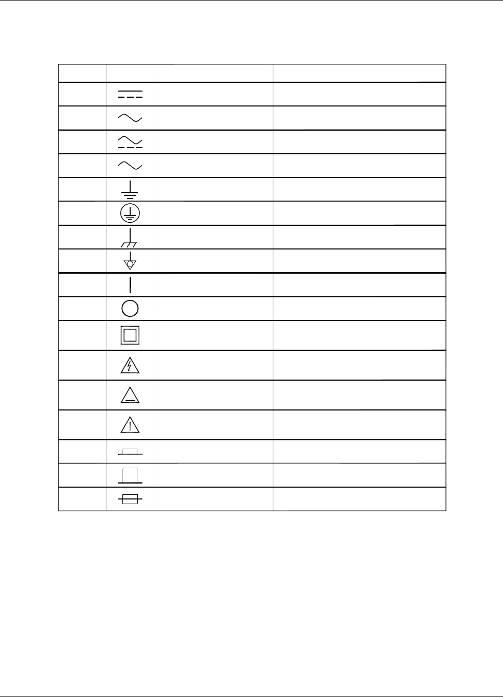
1.4 SAFETY SYMBOLS
Number Symbol
1
2
3
4
5
6
7
8
9
10
11
12
13
14
15
16
None
Publication Description
IEC 417, No. 5031 Direct current
IEC 417, NO. 5032
IEC 417, No. 5033 Both direct and alternating current
IEC 617-2, No. 02-02-06 Three-phase alternating current
IEC 417, No. 5017 Earth (ground) TERMINAL
IEC 417, No. 5019 PROTECTIVE CONDUCTOR TERMINAL
IEC 417, No. 5020 Frame or chassis ground
IEC 417, No. 5021 Equipotentiality
IEC 417, No. 5007 On (supply)
IEC 417, No. 5008 Off (supply)
IEC 417, No. 5172 DOUBLE INSULATION OR REINFORCED
Bcakground color-yellow Caution, risk of electric shock
Background color-yellow Caution, hot surface
Background color-yellow Caution (refer to accompanying documents)
IEC 417, No. 5268-a In-position of bistable push control
IEC 417, No. 5269-a Out-position of bistable push control
IEC 1010-1 Fuse
Alternating current
Equipment protected by
INSULATION
ISO 3864, No. B.3.6
IEC 417, No. 5041
ISO 3864, No. B.3.1
Symbol and outline-black
Symbol and outline-black
Symbol and outline-black
3
~
~
~

Lake Shore Model 642 Electromagnet Power Supply User’s Manual
1-10 Introduction
This Page Intentionally Left Blank

Lake Shore Model 642 Electromagnet Power Supply User’s Manual
Magnet System Design 2-1
CHAPTER 2
MAGNET SYSTEM DESIGN,
INSTALLATION, AND OPERATION
2.0 GENERAL
This chapter provides the user insight into the design, installation, and operation of a typical electromagnet. For
information on how to install the Model 642 please refer to Chapter 3. For Model 642 operation information, refer to
Chapter 4.
2.1 INTRODUCTION
A magnet used with the Model 642 Power Supply is typically an iron pole, twin coil, 4-inch pole diameter, variable air
gap, water cooled electromagnet. Larger magnets can be used depending on their electrical parameters and the magnetic
field requirements. The electromagnet provides a uniform magnetic field in the air gap between two adjustable poles.
The samples, which are to be tested for their magnetic properties, are placed in the air gap with appropriate monitoring
equipment attached. By varying the polarity and intensity of the field, useful data can be collected. A typical
electromagnet is shown in Figure 2-1.
Figure 2-1. A Typical Electromagnet

Lake Shore Model 642 Electromagnet Power Supply User’s Manual
2-2 Magnet System Design
2.2 MAGNET CONSTRUCTION
The magnet consists of two water-cooled coils surrounding adjustable iron poles, which are fitted into an iron frame.
The frame supports the poles and coils, and improves the magnet’s efficiency. The iron poles are fitted with adjusting
mechanisms so that the air gap width can be set. Lock mechanisms are provided to hold the poles in place after
adjustment is made. The poles faces have pole caps attached, which provide the desired magnetic focus. The size and
shape of the pole caps are chosen according to the size of sample being tested and the magnetic field requirement.
2.3 CONNECTING THE MAGNET
Connecting the magnet to the power supply requires three separate circuits: the cooling water hoses, the main high
current power lines, and the safety switches which may include any combination of temperature and flow switches.
These connections are shown below.
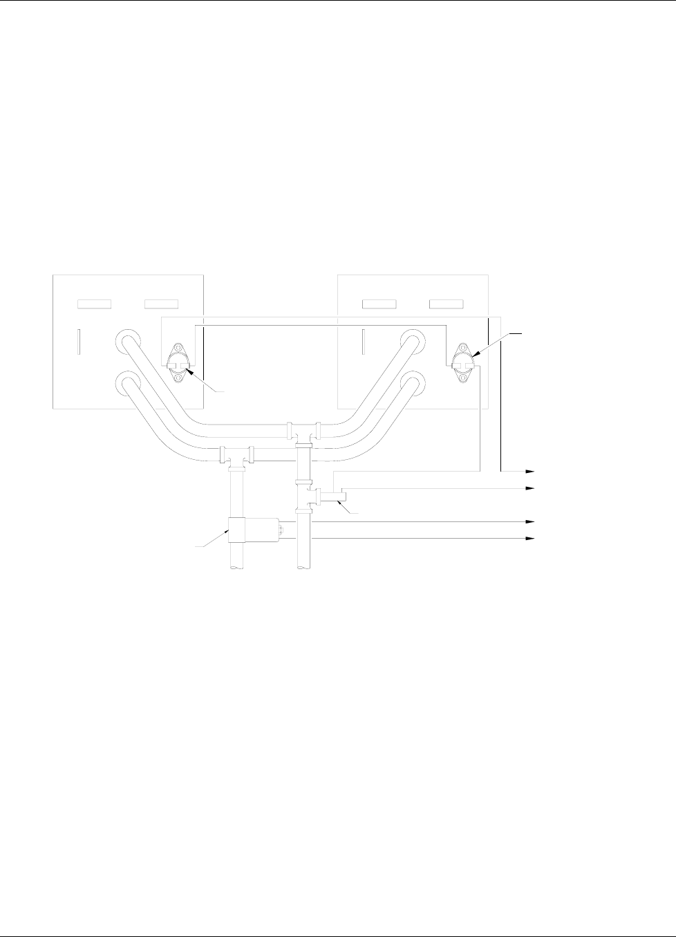
2.3.1 Water Hose Connection
Water-cooling is essential for these magnets. The power dissipated can raise the temperature of the coils to the point
where they will be destroyed. In addition, the samples being tested may exhibit changes in their magnetic performance
with changes in temperature causing errors in the collected data. Typical water connection is shown in Figure 2-2. The
magnets may be supplied with hose barbs or standard hose fittings. The coils are connected in parallel so that the water
temperature rise is the same for both. Every effort should be made to insure that the flow rate in both coils is the same.
The minimum flow required is usually specified by the magnet vendor.
HOSE CLAMP
HOSE BARB FITTING
MAGNET WATER CONNECTION
REENFORCED HOSE
WATER FILTER
WATER VALVE
TEE
OPTIONAL FLOW SWITCH
MAGNET COIL
HOSE BARB FITTING
HOSE CLAMP
REENFORCED HOSE
Figure 2-2. Typical Magnet Water Hook-Up
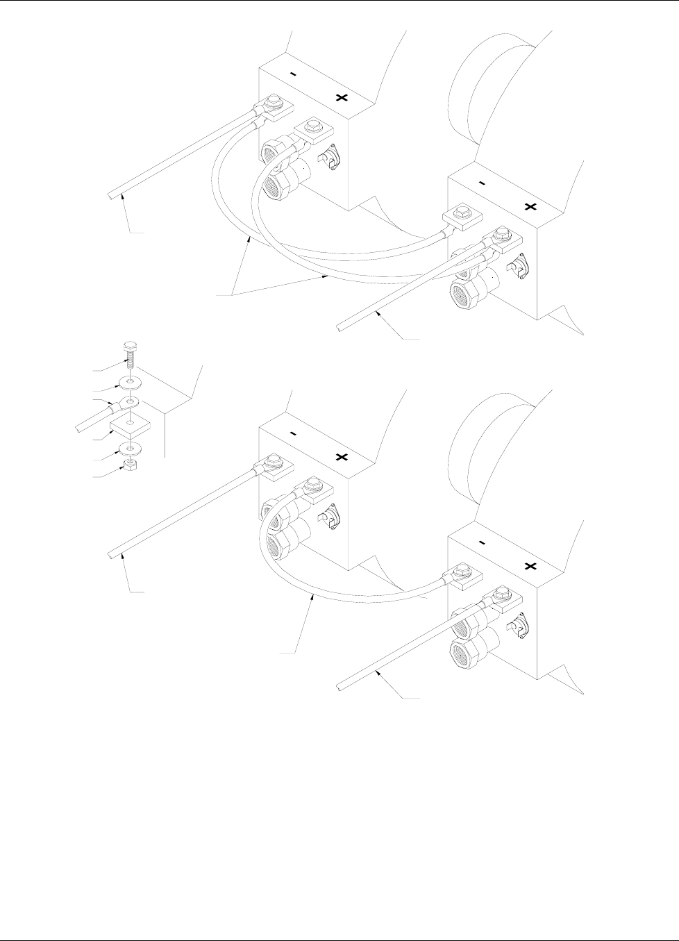
2.3.2 Magnet Coil Wiring
Typical magnet coil wiring is shown in Figure 2-3. The connecting cable used should be of sufficient gage to prevent
excessive voltage drop and heat rise in the cable. The cables should be as short as possible to minimize the voltage drop.
Current carrying capacities for various sizes of cables and cable lengths are shown in Table 3-3. The connections must be
made with the correct size of hardware for the magnet terminal. We recommend the use of a spring or Belleville washer
for cable terminations. When the parts of a connection expand and contract with changes in temperature, they tend to
loosen. A spring washer will reduce this tendency.
Lake Shore Model 642 Electromagnet Power Supply User’s Manual
Magnet System Design 2-3
POWER LEAD
POWER LEAD
CROSS CONNECTION WIRING
POWER LEAD
POWER LEAD
CROSS CONNECTION WIRING
BOLT
BELLEVILLE WASHER
CABLE CONNECTION
MAGNET POWER LUG
PLAIN WASHER
NUT
(PARALLEL WIRING)
(SERIES WIRING)
Figure 2-3. Typical Magnet Coil Wiring Showing Series and Parallel Connections
Lake Shore Model 642 Electromagnet Power Supply User’s Manual
2-4 Magnet System Design
2.3.3 Temperature Switches and Flow Switches
As discussed in Section 2.3.1, water-cooling for the magnet is essential. To protect the magnet from damage resulting
from an interruption in cooling water, a flow switch, temperature switches or both should be installed. The switches must
have a normally closed contact, and if multiple switches are used, they must be connected in series. The switches are
then connected to the Flow Switch terminals of the Magnet Connector on the Model 642. The Model 642 monitors the
switches and if an open is detected, the output current is ramped to zero. (Flow switch monitoring depends on water
valve mode setting. See sections 4.12 and 4.13 for details.)Given the cost of the magnet, it is prudent to use both
temperature and flow switches. Some installations use two flow switches, one in the exhaust line of each coil so that if a
clog occurs in only one coil, it can be detected. Figure 2-4 shows the typical flow and temperature switch connection.
CAUTION: Care must be used in the selection of the flow switch. Some switches use a sensitive reed switch,
which can be overpowered by stray flux from the magnet and will not open when the magnet is
operating at high field. The flow switch must be tested by turning off the water while the magnet is
operating at full current.
THERMAL SWITCH
FLOW SWITCH
WATER VALVE
TO 642 MAGNET CONNECTOR VALVE CONTACTS
TO 642 MAGNET CONNECTOR FLOW SWITCH CONTACTS
INLET OUTLET
THERMAL SWITCH
Figure 2-4. Typical Thermal Switch, Flow Switch and Valve Wiring
2.3.4 Cooling Water and Water Valve
The cooling water for the magnet can be drawn from the municipal water facility or from a dedicated re-circulating water
chiller designed for this purpose. When water is drawn from the municipal water facility, the water should be turned on
only when it is required to reduce consumption and reduce the likelihood of scale build-up in the magnet. The water can
be turned on and off manually when the magnet is used, or automatically with a solenoid valve. The Model 642 provides
automatic control and a 24 VAC at 1 A output for this purpose. The optional water valve is shown in Figure 2-2. The
water inlet line should also be fitted with a sediment filter (not shown) to reduce scale build-up in the magnet coils and
connecting lines.
2.3.5 Grounding
A ground connection (tapped hole) is usually available at the rear of the electromagnet frame. This ground point is
provided for customers who would like to use the electromagnet frame as a signal ground or will be bringing hazardous
live voltages near the electromagnet and would like to make it an electrical safety ground. Please verify suitability for
such a function and compatibility with local and national electrical codes before making ground connections. Scrape off
excess paint near the connecting screw to ensure a good electrical contact with the bare steel of the electromagnet frame.
Lake Shore Model 642 Electromagnet Power Supply User’s Manual
Magnet System Design 2-5
2.3.6 Final Check-Out
When all of the connections have been made the system should be tested to be sure it is operating correctly. The settings
for the magnet water should be checked to verify that they are correct for the configuration which has been installed
(Refer to Section 4.12 – Magnet Water). The maximum current setting for the magnet should be set also (Refer to
Section 2.4.2 and Section 4.11.1.)
2.4 ELECTROMAGNET OPERATION
This section provides a brief description of the typical operation of an electromagnet. For operation of the Model 642,
refer to Chapter 4.
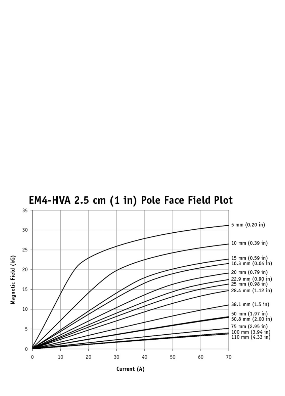
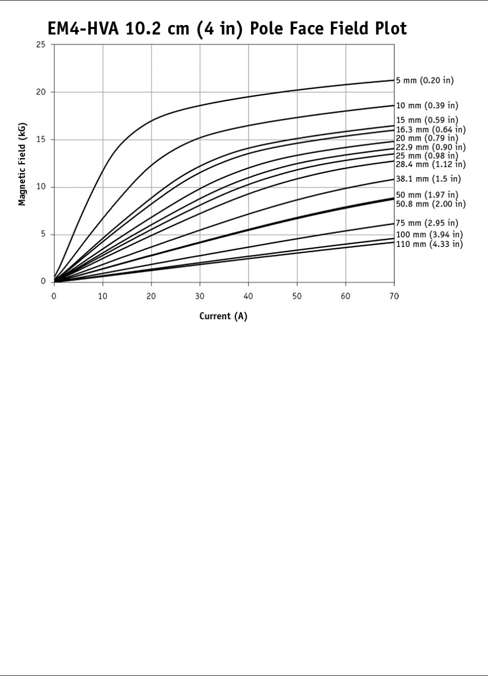
2.4.1 Air Gap and Pole Caps
The first step in setting up a magnet for operation is to select the proper pole caps and adjust the air gap. These
parameters are determined by the size and shape of the sample, and the connections that must be made to the sample.
Generally, a smaller pole face provides a higher field within the air gap. A smaller air gap also provides a higher field.
The pole faces must be selected to accommodate the size of the sample being tested. The air gap is selected based on the
size of the sample and the other equipment being used. The curves for Field versus Current for various air gaps and pole
cap sizes for the Lake Shore Model EM4-HVA are shown in Figure 2-5. It also shows that these parameters are not
linear. This must be taken into account when operating an electromagnet. To obtain linearity, it is necessary to operate
the magnet and power supply under field control. (Refer to Section 2.4.4)
2.4.2 Maximum Current and Power
The Model 642 was designed to operate with a magnet load resistance of 0.50 Ω, but will work with a resistance range of
0.40 Ω to 0.60 Ω. The resistance of a magnet will rise with a rise in temperature and this should be taken into account.
The power dissipated in the magnet is given by: P=I2R. If the current remains constant, the power dissipated will rise
proportionately with the rise in resistance. The Model 642 allows the user to set a maximum current limit to prevent
damage to the magnet. (Refer to Section 4.11.1.)
Figure 2-5. Typical Curves of Field vs. Current for Various Air Gaps and Pole Cap Sizes (Sheet 1 of 3)
Lake Shore Model 642 Electromagnet Power Supply User’s Manual
2-6 Magnet System Design
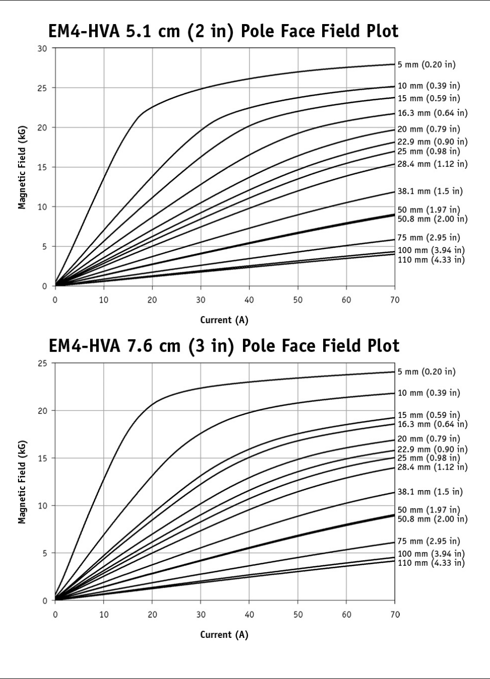
Figure 2-5. Typical Curves of Field vs. Current for Various Air Gaps and Pole Cap Sizes (Sheet 2 of 3)
Lake Shore Model 642 Electromagnet Power Supply User’s Manual
Magnet System Design 2-7
Figure 2-5. Typical Curves of Field vs. Current for Various Air Gaps and Pole Cap Sizes (Sheet 3 of 3)
2.4.3 Operation Under Field Control
To obtain a linear field ramp, a magnetic sensor such as a Hall probe is placed in the air gap along with the sample being
tested. The sensor is connected to a Gaussmeter. The output of the Gaussmeter is used to correct the programming input
to the power supply. In this way non-linearity can be corrected. Lakeshore manufactures probes and Gaussmeters for this
purpose.
Lake Shore Model 642 Electromagnet Power Supply User’s Manual
2-8 Magnet System Design
2.4.4 Avoiding Cooling Water Condensation
If the temperature of the cooling water is too cool relative to the air temperature and humidity, condensation can occur.
Condensation inside the power supply can cause severe damage. To avoid condensation, the power supply operator must
remain cognizant of the ambient air temperature, cooling water temperature, and the relative humidity. Lake Shore
defines the limits of these conditions as follows: ambient temperature = 18 – 28 °C (64 – 82 °F), cooling water
temperature = 15 – 25 °C (59 – 77 °F), and humidity = 20 – 80% (non-condensing). Knowing the actual state of these
conditions, the operator can calculate the dew point, or temperature at which condensation will occur. Tables 2-1 and 2-2
are included to aid in dew point calculation.
Table 2-1. Dew Point Calculation Table (In Degrees Celsius)
% Relative Humidity
°C 100 95 90 85 80 75 70 65 60 55 50 45 40 35 30 25 20 15 10
32 32 31 31 29 28 27 26 24 23 22 20 18 17 15 12 9 6 2 0
29 29 28 27 27 26 24 23 22 21 19 18 16 14 12 10 7 3 0 –
27 27 26 25 24 23 22 21 19 18 17 15 13 12 10 7 4 2 0 –
24 24 23 22 21 20 19 18 17 16 14 13 11 9 7 5 2 0 – –
21 21 20 19 18 17 16 15 14 13 12 10 8 7 4 3 0 – – –
18 18 17 17 16 15 14 13 12 10 9 7 6 4 2 0 – – – –
16 16 14 14 13 12 11 10 9 7 6 5 3 2 0 – – – – –
Table 2-2. Dew Point Calculation Table (In Degrees Fahrenheit)
% Relative Humidity
°F 100 95 90 85 80 75 70 65 60 55 50 45 40 35 30 25 20 15 10
90 90 88 87 85 83 81 79 76 74 71 68 65 52 59 54 49 43 36 32
85 85 83 81 80 78 76 74 72 69 67 64 61 58 54 50 45 38 32 –
80 80 78 77 75 73 71 69 67 65 62 59 56 53 50 45 40 35 32 –
75 75 73 72 70 68 66 64 62 60 58 55 52 49 45 41 36 32 – –
70 70 68 67 65 63 61 59 57 55 53 50 47 44 40 37 32 – – –
65 65 63 62 60 59 57 55 53 50 48 45 42 40 36 32 – – – –
60 60 58 57 55 53 52 50 48 45 43 41 38 35 32 – – – – –
Example: Determine the actual air temperature and relative humidity. Find the closest air temperature in the left-hand
column and the closest relative humidity across the top. If the air temperature is 24 °C (75 °F) and the relative humidity
is 35%, the intersection of the two shows a dew point of 7 °C (45 °F). Therefore, for the given conditions, the cooling
water must remain above 7 °C (45 °F) to prevent condensation.

Lake Shore Model 642 Electromagnet Power Supply User’s Manual
Installation 3-1
CHAPTER 3
INSTALLATION
3.0 GENERAL
This chapter provides general installation instructions for the Model 642 Electromagnet Power Supply. CAUTION: To
ensure the best possible performance and maintain operator safety, read this entire chapter before installing the
instrument and applying power. Serious hazards can exist when an instrument of this power capacity is used incorrectly.
If you do not understand any section of this manual, consult Lake Shore for clarification. Lake Shore Cryotronics
assumes no responsibility for damage or injuries incurred due to improper installation, defeat of any of the safety
features or misuse of this power supply.
3.1 INSPECTION AND UNPACKING
Inspect shipping containers for external damage before opening them. Photograph any container that has significant
damage before opening it. If there is visible damage to the contents of the container, contact the shipping company and
Lake Shore immediately, preferably within 5 days of receipt of goods. Keep all damaged shipping materials and contents
until instructed to either return or discard them.
Open the shipping container and keep the container and shipping materials until all contents have been accounted for.
Check off each item on the packing list as it is unpacked. Instruments themselves may be shipped as several parts. The
items included with the Model 642 are listed below. Contact Lake Shore immediately if there is a shortage of parts or
accessories. Lake Shore is not responsible for any missing items if not notified within 60 days of shipment.
Inspect all items for both visible and hidden damage that occurred during shipment. If damage is found, contact Lake
Shore immediately for instructions on how to file a proper insurance claim. Lake Shore products are insured against
damage during shipment but a timely claim must be filed before Lake Shore will take further action. Procedures vary
slightly with shipping companies. Keep all shipping materials and damaged contents until instructed to either return or
discard them.
If the instrument must be returned for recalibration, replacement or repair, a returned goods authorization (RA) number
must be obtained from a factory representative prior to return. The Lake Shore RA procedure is given in Paragraph 7.2.
Items Included with Model 642 Electromagnet Power Supply:
1 – Model 642 Instrument
1 – Model 642 User’s Manual
2 – Front Handles (shipped attached)
2 – Rear Handles (shipped attached)
1 – Analog I/O Mating Connector
1 – Output Terminal Fasteners (set)
1 – Wiring Cover Plate and Screws
2 – 4 Pin Detachable Terminal Blocks
1 – 8 Pin Detachable Terminal Block
2 – Hose Clamps
1 – Output Lug Cover and Screws
3.1.1 Moving and Handling
Four handles are provided for ease of moving and handling the Model 642. The handles can be used in place of lifting
lugs when cloth straps are used. Always use all four handles when moving the Model 642. Because of its weight, the
Model 642 should be handled by mechanical means. If for some reason it is necessary to move it by hand, a minimum
of two people is required.
CAUTION: To avoid injury to personnel, always observe proper lifting techniques in accordance with OSHA
and other regulatory agencies.

Lake Shore Model 642 Electromagnet Power Supply User’s Manual
3-2 Installation
3.2 REAR PANEL DEFINITION
This paragraph defines the rear panel of the Model 642. Refer to Table 3-1. Readers are referred to paragraphs that
contain installation instructions and connector pin-outs for each feature.
CAUTION: Verify that the Model 642 has been set up for the proper line voltages.
CAUTION: Make rear panel connections with the instrument power off.
Table 3-1 below highlights the connections to be made on the rear panel. Figure 3-1 shows the rear panel and identifies
the connectors.
Table 3-1. Rear Panel Connector Identification
1 VOLTAGE
SELECTION 16 DIN terminals are provided behind a wiring cover to facilitate setting the correct input
voltage.
2 CIRCUIT
BREAKER An adjustable current auto-resetting circuit breaker is provided behind a wiring cover to
protect main power circuits.
3 FUSES ¼ A Class CC fuses (2) are provided behind a wiring cover to protect the start-up circuit.
4 CABLE ENTRY A 34 mm (1.3 inch) hole is provided for power cable entry and strain relief bushing.
5 POWER
TERMINALS Four DIN terminals are provided behind a wiring cover for connection of power wiring.
6 MAGNET
CONNECTOR A 4-pin detachable screw terminal block is provided to connect the optional magnet
water valve power and temperature and/or flow switch.
7 AUXILIARY
CONNECTOR An 8-pin detachable screw terminal block is provided to connect the optional Emergency
Stop, Remote Fault Indicator, Remote Enable and Chassis Ground.
8 POWER SUPPLY
CONNECTOR A 4-pin detachable screw terminal block is provided to connect the optional power
supply water valve power and/or flow switch.
9 COOLING
WATER Two 10 mm (3/8”) hose barbs are provided for input and output of cooling water.
10 OUTPUT
TERMINALS Two output lugs are provided for the magnet cable connections. Refer to Paragraph 3.8
and Figures 3-13 and 3-14 for connecting the magnet cables to the instrument.
11 ANALOG I/O A 15-pin D subminiature connector provides output for current and voltage monitoring,
as well as analog programming input. Refer to Paragraph 3.9 and see Figure 7-7.
12 RS-232C (DTE) A 9-pin D subminiature plug wired in DTE configuration is provided for use with RS-
232C serial computer interface. Refer to Paragraph 5.2.2 and see Figure 7-11.
13 IEEE-488
INTERFACE An IEEE-488 compliant interface connector is provided for use with IEEE-488 parallel
computer interface. Refer to Paragraph 5.1 and Figure 7-12.
14 CHASSIS
CONNECTION An earth safety chassis connection is provided to facilitate connection to the magnet
frame if noise problems exist.
15 DETACHABLE
HANDLES Two high-strength detachable handles are provided to aid in handling and lifting.
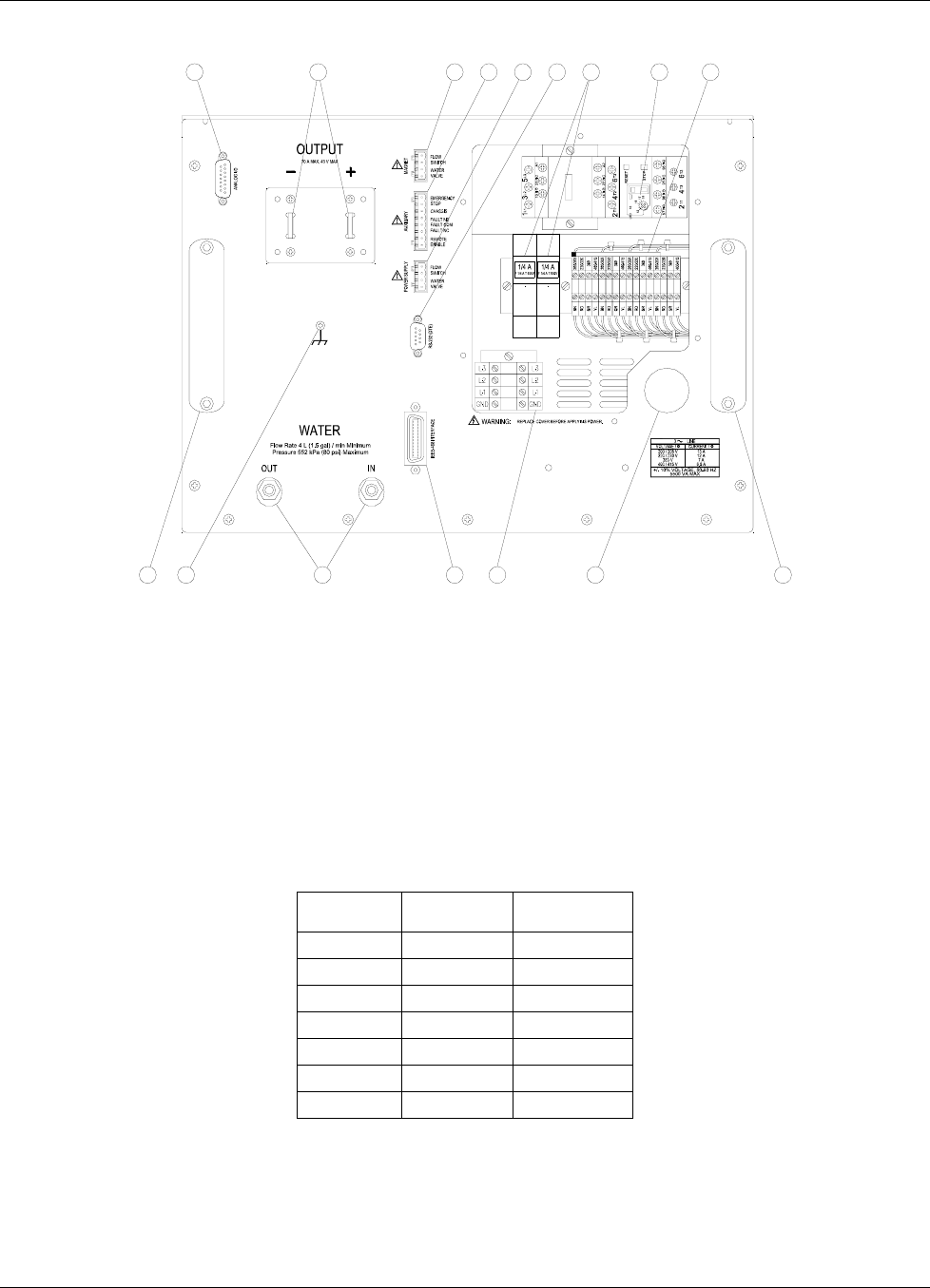
Lake Shore Model 642 Electromagnet Power Supply User’s Manual
Installation 3-3
12
3
12
87610
159
14 1315
11
54
Figure 3-1. Model 642 Rear Panel (shown with wiring cover removed)
3.3 POWER WIRING AND SET-UP
This section describes how to properly connect the Model 642 to the line power. Please follow these instructions
carefully to ensure proper operation of the instrument and the safety of operators.
3.3.1 Line Voltage Selection
The Model 642 has four AC line voltage configurations covering seven different input voltages. The nominal voltage and
voltage tap setting as well as the circuit breaker current setting for each configuration is shown in Table 3-2. Verify that
the unit is configured correctly for the voltage being applied to the unit before applying power.
Table 3-2. Voltage and Current Selection
Nominal
Voltage Voltage
Tap Circuit
Breaker
200 V 204 V 18 A
208 V 204 V 18 A
220 V 225 V 17 A
230 V 225 V 17 A
380 V 380 V 12 A
400 V 408 V 12 A
415 V 408 V 12 A
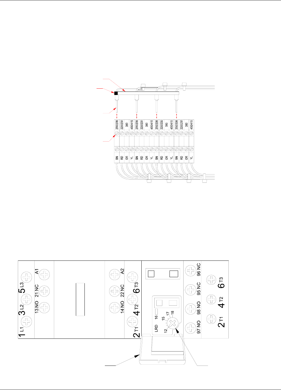
Lake Shore Model 642 Electromagnet Power Supply User’s Manual
3-4 Installation
Line Voltage Selection (Continued)
Changing line voltage is accomplished by moving four wires to the required voltage terminals. The required location is
shown in Figure 3-2. To change the voltage setting, loosen the four terminal screws in the voltage-change terminal block
to which the wires are connected and move the wires to the required voltage position. The wires are held in place in a
locator card to maintain their spacing and prevent mis-wiring. The screws in the new terminal location must be loosened
four full turns to allow the entry of the wires. Move all four wires at once by lifting the locator card to extract the wires
from the terminals. Move the card and wires to the correct location and insert the wires completely so that the card rests
against the terminals. While holding the locator card in place to keep the wires fully inserted, tighten the terminal screws.
The recommended torque requirement is 0.5 Nm. Also, tighten the four terminals where the wires were previously.
TERMINAL SCREW
WIRE FERRULE
VOLTAGE SELECTOR CARD
VOLTAGE INDICATOR KEY
Figure 3-2. Voltage Change Detail
3.3.2 Circuit Breaker Setting
The circuit breaker is an important safety feature of the Model 642. The required current setting depends on the voltage
for which the unit is wired. (Refer to Table 3-2.) Verify that the circuit breaker is set correctly for the line voltage being
applied to the unit. To set the breaker trip current, open the access cover on the circuit breaker and adjust the current
setting dial to the correct value. (See Figure 3-3.)
NOTE: The circuit breaker has an automatic reset feature. If the breaker trips, it will reset within a few minutes and
the unit can be restarted. If the units trips again after a short time, the trip current may be set incorrectly.
CURRENT SETTING DIALACCESS COVER
Figure 3-3. Circuit Breaker
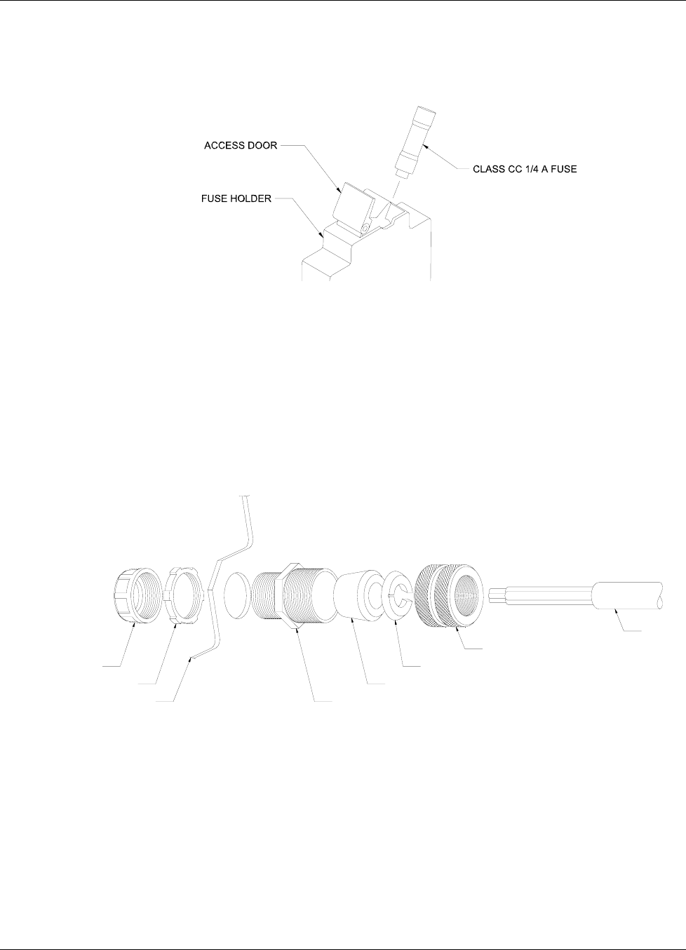
Lake Shore Model 642 Electromagnet Power Supply User’s Manual
Installation 3-5
3.3.3 Start-up Fuses
The start-up transformer and associated circuitry are energized whenever the power is connected. To protect this
circuitry, two ¼ A, class CC fuses are provided. A fuse is accessed by pulling open the access door on the fuse holder as
shown in Figure 3-4. The fuses are inserted small-end first as shown.
Figure 3-4. Fuses
3.3.4 Cable Entry
A 34 mm (1.3 inch) diameter hole is provided for the power cable to enter the unit. A bushing is provided which will
accommodate a 16-19 mm (0.62-0.75 in) round neoprene jacketed cable (See Chapter 6). If a different cable is used, a
strain relief of the appropriate type and size must be provided by the installing agency.
CAUTION: Failure to install a strain-relief bushing is a hazard and could cause injury or death to operating
personnel in the event of a fault. Lake Shore reserves the right to void the warranty of any instrument not properly
installed.
A typical cable entry with bushing is shown in Figure 3-5.
BUSHING BODY
COMPRESSION GROMMET
SLIP WASHER
COMPRESSION COLLAR
CABLE
642 REAR PANEL
LOCKING RING
CONDUIT BUSHING
Figure 3-5. Typical Cable Entry with Bushing
3.3.5 Power Input Terminals
The Model 642 requires a 4 conductor power cord (not included). The input to the Model 642 is wired in a delta
configuration, but will operate from a delta or wye source. If operating from a wye source, the neutral line (N) is not
used. The ground (the green/yellow ground terminal) connects the instrument chassis to the electrical ground (safety
ground), and is required to prevent fault conditions which may be hazardous to operating personnel. In no case should
the safety ground line be omitted. In no case should a neutral line be used as a safety ground. If a detachable cord is used,
always plug the power cord into a properly grounded receptacle to ensure safe operation of the instrument. All wiring
must comply with the code requirements of the locality in which the instrument is installed. Figure 3-6 shows typical
input wiring. The wire ferrules shown are not required, but are recommended to prevent stray strands from shorting to
adjacent terminals.
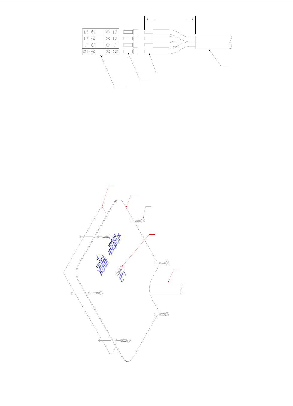
Lake Shore Model 642 Electromagnet Power Supply User’s Manual
3-6 Installation
POWER CABLE
STRIP 13mm (0.5 in)
WIRE FERRULE (OPTIONAL)
POWER TERMINALS
140 mm (5.5 in)
Figure 3-6. Typical Power Input Wiring
3.3.6 Wiring Cover
When the power wiring, voltage setting and current setting are complete, install the wiring cover with the six (6)
6-32 × 3/8 screws provided. The wiring cover installation is shown in Figure 3.7. Be sure that the voltage indicator tab
of the voltage locator card (Figure 3.2) shows through the correct indicator slot in the wiring cover.
WARNING: Do not connect power or attempt to operate the unit with this cover removed. Lethal voltage and
currents exist inside. There is a risk of injury or death if an operator or technician comes in contact
with these potentials.
CHASSIS
WIRING COVER
6-32 X 3/8 SCREW
(6)
POWER CORD
VOLTAGE INDICATOR SLOTS
Figure 3-7. Wiring Cover Installation
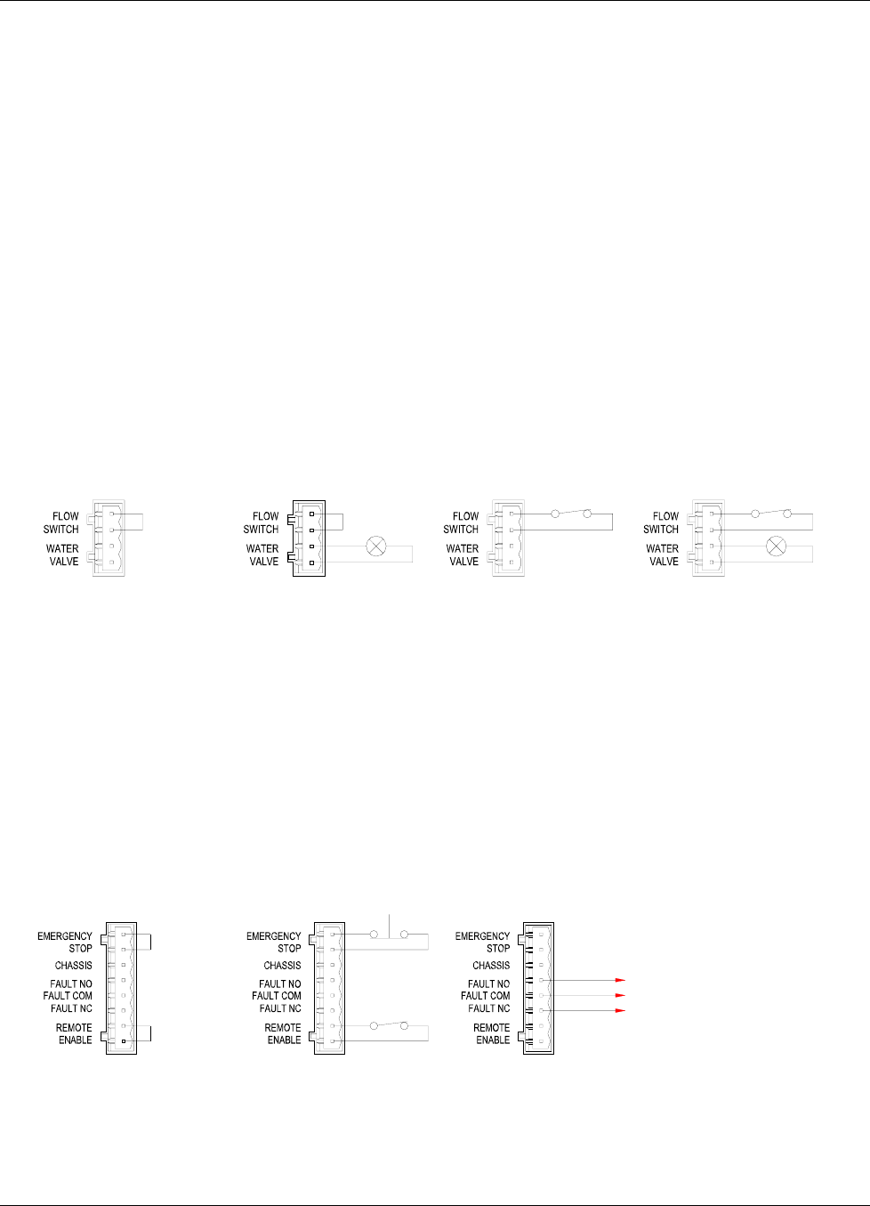
Lake Shore Model 642 Electromagnet Power Supply User’s Manual
Installation 3-7
3.3.7 Mains Wiring
No cord or disconnecting plug is provided with the unit. In all cases, the field connection of the mains wiring shall
comply with all local wiring codes where the Model 642 is installed. The power source shall be protected with a
dedicated circuit breaker or fuse. The rating of the protection device shall be a value equal to that of the internal breaker
or the next higher commercially available value (See Table 3-2). If the Model 642 is connected with permanent wiring, a
disconnect switch shall be installed. The disconnect switch shall be located within 3 meters (10 feet) of the Model 642,
be clearly marked in layman’s language and be easily accessible.
3.4 MAGNET CONNECTOR
The magnet connector provides terminals for an optional magnet temperature switch or magnet water flow switch and an
optional magnet water control solenoid valve. The flow or temperature switch must have a normally closed contact rated
at 5 V at 10 mA. A contact closure is required to enable the Model 642 output. If a switch is not used, a jumper is
required. 24 VAC at 1 A is provided to operate a solenoid water valve for the magnet. This output is controlled by the
power supply, either automatically via software, or manually through the Magnet Water menu.
Water control is desirable to reduce water consumption when the water comes from a municipal facility. Turning the
water off when it is not required also reduces the probability of condensation on the magnet or connecting hoses. If the
cooling water comes from a facility chiller system, condensation is not usually a problem and a control valve is not
required. In this case, it is appropriate to install a flow switch (optional) or temperature switch (optional) to monitor the
water flow and protect the magnet in the event of a water flow interruption. Figure 3-8 shows examples of typical
magnet connector wiring.
NO VALVE OR SWITCH VALVE ONLY SWITCH ONLY VALVE AND SWITCH
Figure 3-8. Typical Magnet Connector Wiring
3.5 AUXILIARY CONNECTOR
The Auxiliary connector provides terminals for an emergency stop, contacts for a remote alarm, remote enable and a
chassis connection. The Emergency Stop must have a normally closed contact rated at 24 V at 1 A. When the contact is
opened, it turns off the Model 642. If an Emergency Stop switch is not used, a jumper is required. A normally closed or
normally open contact is provided to control a remote alarm annunciator. This set of contacts is rated at 30 V, 1 A. If it is
desirable to have a remotely located alarm to echo the internal alarm, these contacts can be used with an external power
source and external alarm. The Remote Enable switch must have a normally closed contact rated at 5 V at 10 mA.
contact closure is required to enable the Model 642 output. If a remote enable switch is not used, a jumper is required.
Figure 3-8 shows some typical auxiliary connector wiring. A chassis terminal is provided in the event that any of the
wires require a shield to minimize noise. Figure 3-9 shows some typical Auxiliary Connector wiring.
NO SWITCHES EMERGENCY STOP
&
REMOTE ENABLE
ALARM CONTACTS
TO REMOTE ALARM CIRCUIT
Figure 3-9. Typical Auxiliary Connector Wiring
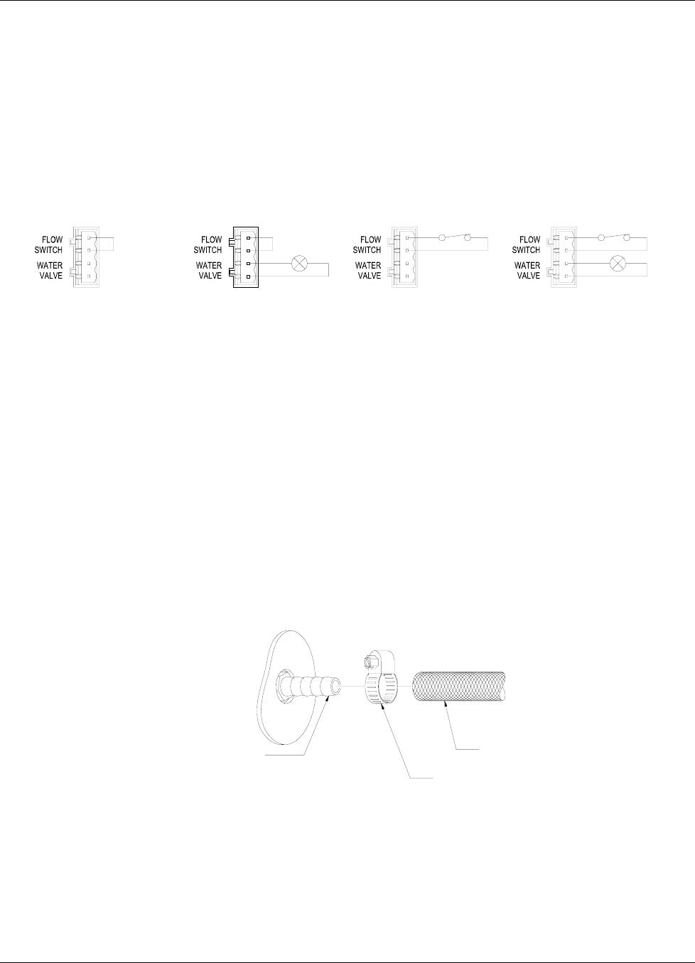
Lake Shore Model 642 Electromagnet Power Supply User’s Manual
3-8 Installation
3.6 POWER SUPPLY CONNECTOR
The Power Supply connector provides terminals for an optional water flow switch and an optional cooling water control
solenoid valve. The flow switch must have a normally closed contact rated at 5 V at 10 mA contact closure is required to
enable the Model 642 output. If a switch is not used, a jumper is required. 24 VAC at 1 A is provided to operate a water
control solenoid valve for the power supply cooling water. This output is controlled by the power supply, either
automatically via software, or manually through the Internal Water menu.
Water control is desirable to reduce water consumption when the water comes from a municipal facility. Turning the
water off when it is not required also reduces the probability of condensation within the power supply and connecting
tubing. If the cooling water comes from a facility chiller system, condensation is not usually a problem and a control
valve is not required. Figure 3-10 shows some typical Power Supply Connector wiring.
NO VALVE OR SWITCH VALVE ONLY SWITCH ONLY VALVE AND SWITCH
Figure 3-10. Typical Power Supply Connector Wiring
3.7 COOLING WATER
Two 10 mm (0.38 in) hose barbs are provided to connect to cooling water. The connection to the cooling water source
should be made with two 10mm (3/8 in) I.D. fiberglass reinforced hoses and two 20mm (25/32 in) adjustable hose
clamps. In addition, we recommend the installation of a sediment filter in the input line. A typical water hose connection
is shown in Figure 3-11.
The cooling water must be clean and free from sediment, salt and other contaminants, which might clog or erode the
water fittings. A minimum flow rate of 5.7 L (1.5 gal) per minute is required with a minimum pressure of 34 kPa (5 psi)
and a maximum pressure of 552kPa (80 psi). The temperature must be kept above 15˚C to avoid condensation and below
30˚C to ensure adequate system cooling. If water is drawn from a local municipal water source, the optional water valve
should be installed for economy and to prevent condensation (See 3.6 Power Supply Connector). If water is supplied by
a facility chiller, a valve can still be used but is not required.
CAUTION: Dot use de-ionized water because it is corrosive to the water fittings inside the Model 642.
HOSE BARB FITTING
ON BACK PANEL OF 642 ADJUSTABLE HOSE CLAMP
REINFORCED HOSE
Figure 3-11. Typical Water Hose Connection
Figure 3-12 shows the connections required when a water valve is used. The optional solenoid water valve is supplied
mounted to a bracket which mounts to the rear of the Model 642 as shown in Figure 3-12. Hose connections are made as
shown in Figure 3-11.
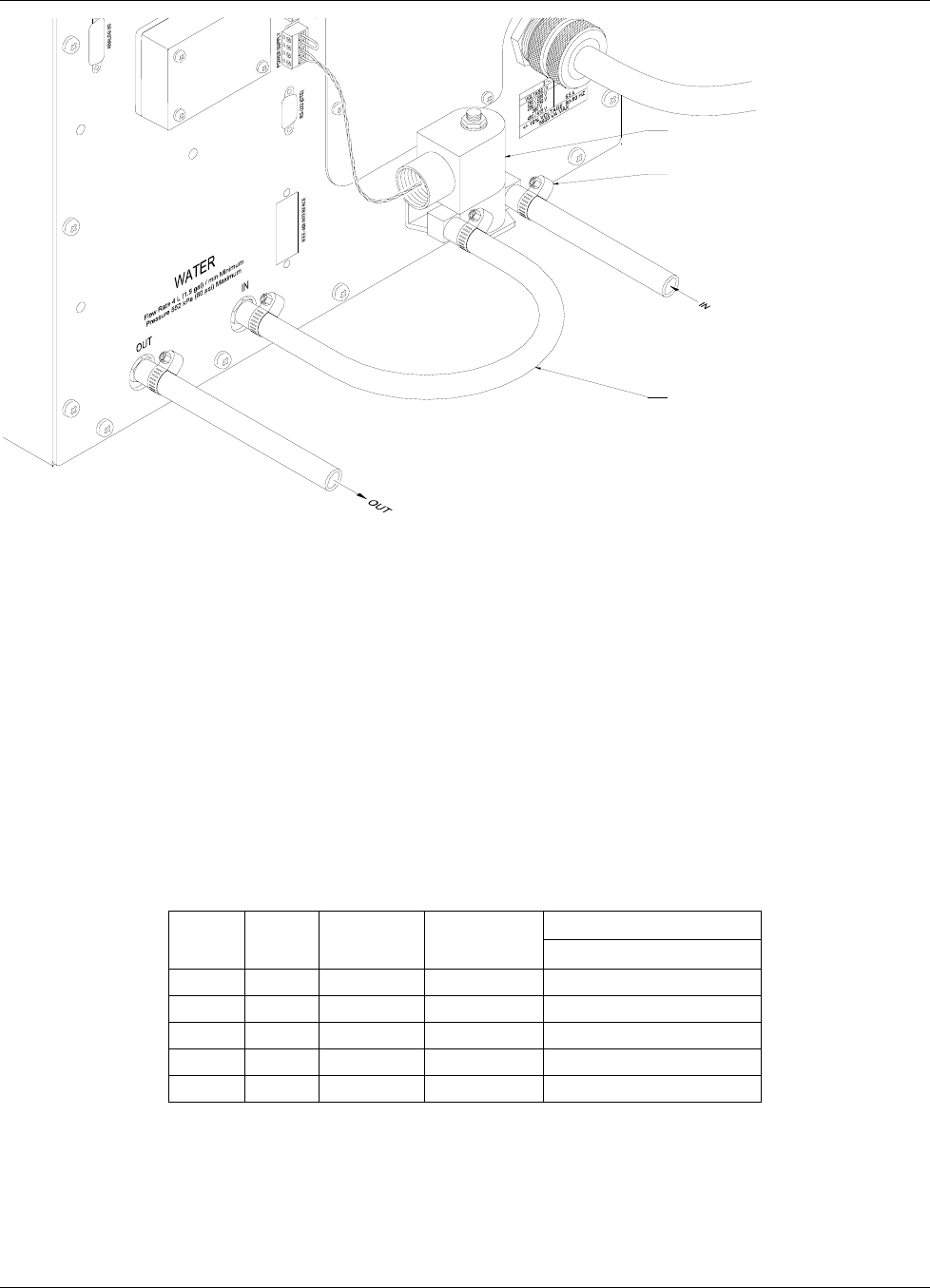
Lake Shore Model 642 Electromagnet Power Supply User’s Manual
Installation 3-9
SOLENOID VALVE
WITH MOUNTING BRACKET
ADJUSTABLE HOSE CLAMP
REINFORCED HOSE
230 mm (9 in) LONG
Figure 3-12. Water Valve Connection
3.8 MAGNET CABLE CONNECTIONS
Magnet cable connections are made at the OUTPUT + and – terminals on the rear panel. These plated copper bus bars
accommodate M6 (¼ inch) mounting hardware. Two ¼-20 bolts, nuts, and Belleville washers are provided. Use load
wires heavy enough to limit the voltage drop to less than 0.5 volts per lead. This ensures proper regulation and keeps the
cables from overheating while carrying the required output current. Table 3-3 lists the current capacity and lead lengths
for load connections. Lake Shore sells magnet cables in 10 and 20 foot lengths. Refer to Paragraph 6.2 for ordering
accessories.
Figure 3-13 shows how the output cables are connected to the Model 642. A plain washer and a spring or Belleville
washer are provided. The Belleville washer is required to maintain contact pressure through varying material thickness
due to heating. The magnet leads should be dressed straight down to allow the installation of the protective lug cover.
Lug cover installation is shown in Figure 3-14.
Table 3-3. Current Capacity and Total Lead Lengths
Distance to Magnet
AWG Area
(mm2) Capacity
(A) Resistivity
Ω
/1000 feet Max Output of 70 A
0 53.5 245 0.09827 22 M (72 ft)
2 33.6 180 0.1563 14 M (45ft)
4 21.2 135 0.2485 8.5 M (28 ft)
6 13.3 100 0.3951 5.5 M (18 ft)
8 8.4 75 0.6282 3.4 M (11 ft)
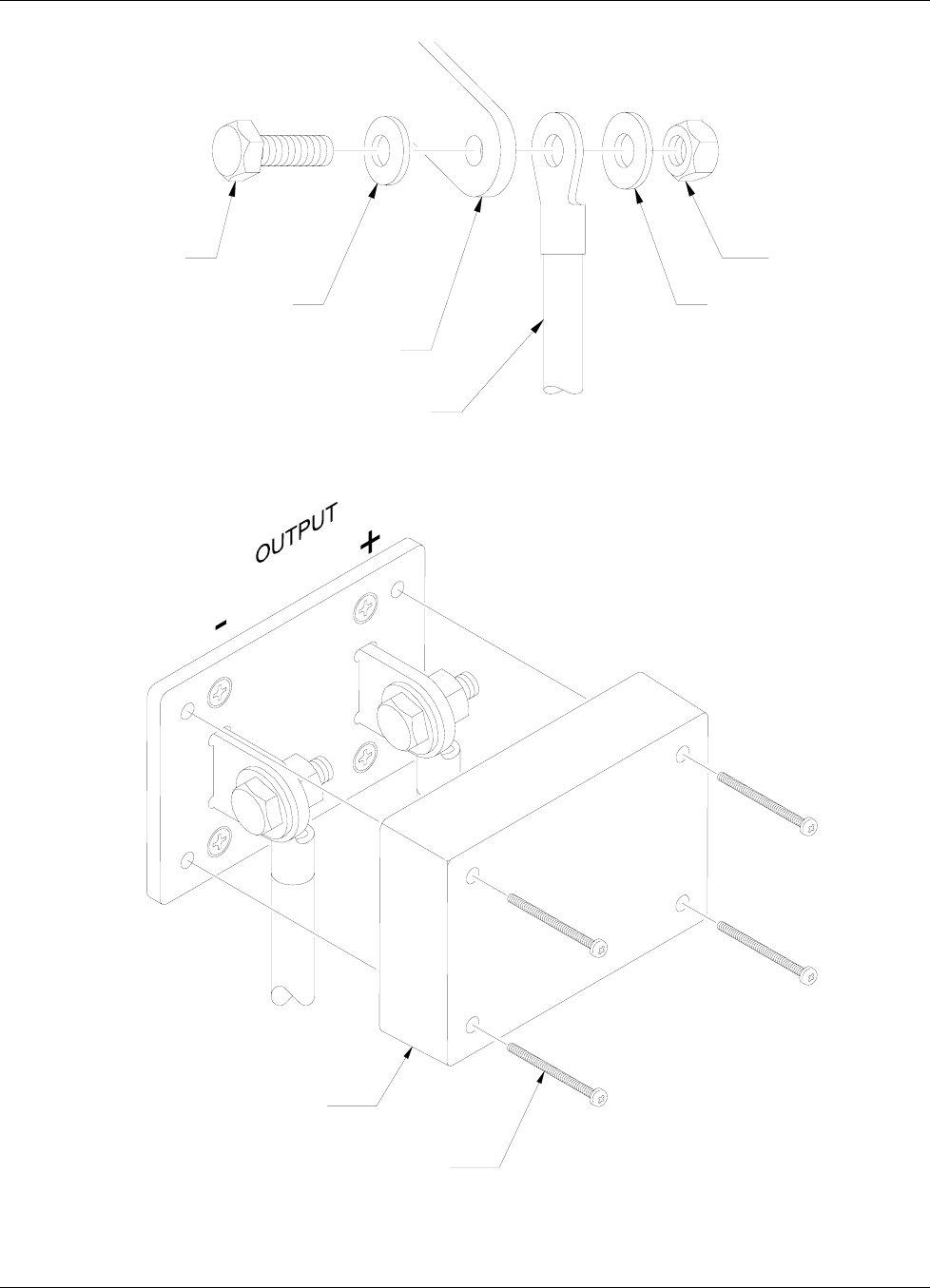
Lake Shore Model 642 Electromagnet Power Supply User’s Manual
3-10 Installation
BELLEVILLE WASHER
BOLT
OUTPUT LUG
MAGNET CABLE
PLAIN WASHER
NUT
Figure 3-13. Output Cable Connection
LUG COVER
38 mm (1.5 in) MOUNTING SCREWS
Figure 3-14. Output Lug Cover Installation
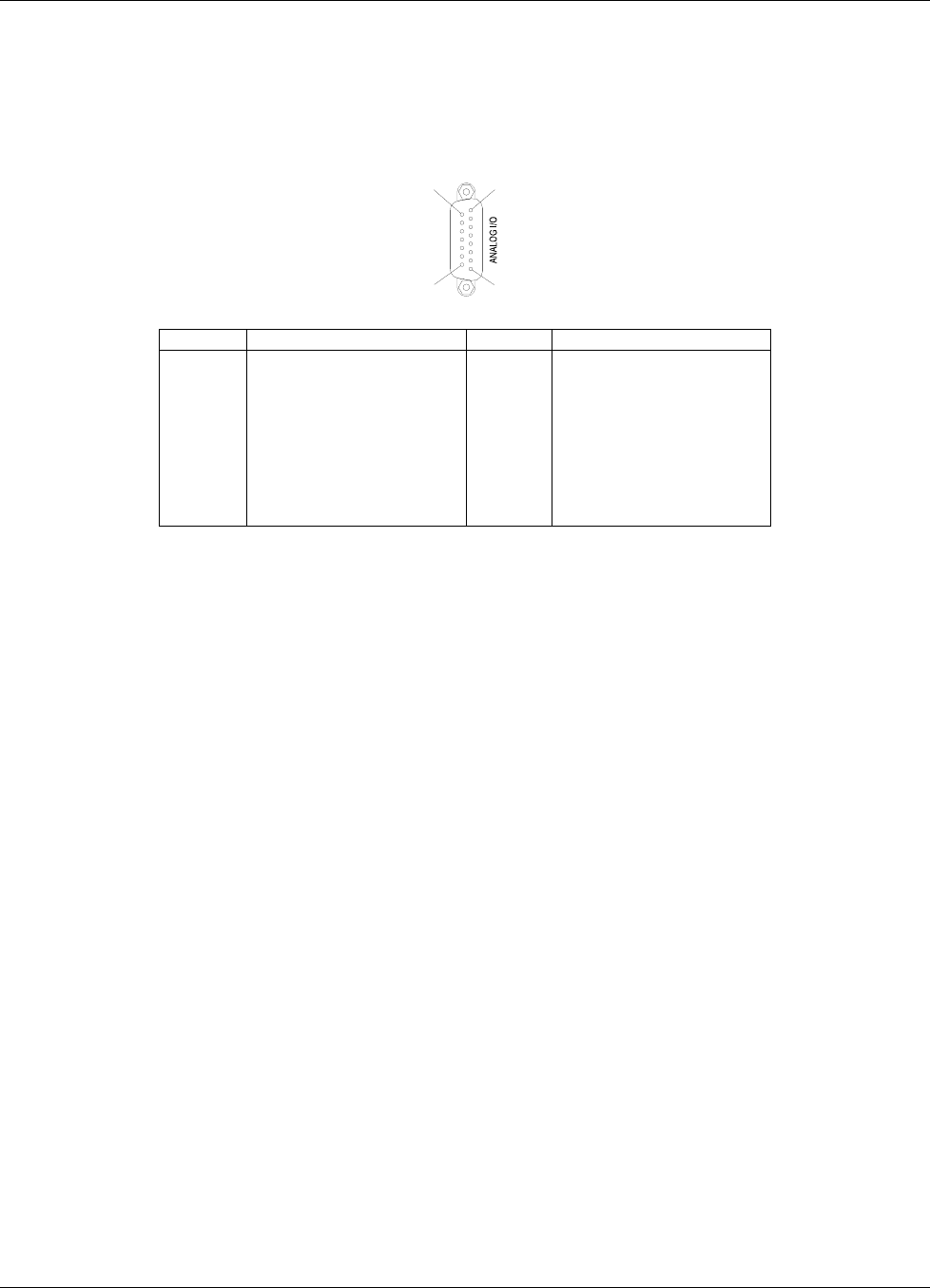
Lake Shore Model 642 Electromagnet Power Supply User’s Manual
Installation 3-11
3.9 ANALOG INPUT/OUTPUT CONNECTIONS
The Analog I/O connector provides connections to analog signals used to monitor or control the power supply. A Current
Program input is provided to control the current output. Two outputs are also provided to monitor the output current and
the output voltage. The connector and pin-out table is shown in figure 3-15. Specific information on each function is
provided in paragraphs 3.9.1 and 3.9.2.
1
815
9
Pin Name Pin Name
1
2
3
4
5
6
7
8
NC
Chassis
Current Program –
Chassis
Voltage Monitor –
Chassis
Current Monitor –
Chassis
9
10
11
12
13
14
15
NC
Chassis
Current Program +
Chassis
Voltage Monitor +
Chassis
Current Monitor +
Figure 3-15. Model 642 Analog Input/Output Connector
3.9.1 External Current Programming
The output current can be programmed externally using an AC or DC voltage. This programming voltage can also be
summed with the internal current setting or ramp. Refer to Paragraph 4.15 to change the external current program mode.
The external current programming input is a differential input with a sensitivity of 10 V = 70 A and an input impedance
of > 50 kΩ. The programming voltage is limited internally to approximately ±10.1 V (Category 1) but care must be taken
to insure that maximum current capability of the magnet is never exceeded.
3.9.2 Output Current and Voltage Monitors
The output current and output voltage of the power supply can be monitored externally using the monitor output
connections on the Analog I/O connector. Each output is a buffered, differential, analog voltage representation of the
signal being monitored. The current monitor has a sensitivity of 7 V = 70 A and the voltage monitor has a sensitivity of
3.5 V = 35V. Both outputs have a source impedance of 20 Ω.
3.10 COMPUTER INTERFACE
The Model 642 can be programmed externally with a computer. Both RS-232C and IEEE-488 ports are provided.
3.10.1 RS-232C Interface Connection
An RS-232C port has been provided to allow remote computer control of the power supply. (Refer to Chapter 5,
Computer Interface Operation)
3.10.2 IEEE-488 Interface Connection
An IEEE-488 port has been provided to allow remote computer control of the power supply. (Refer to Chapter 5,
Computer Interface Operation)
3.11 CHASSIS CONNECTION
A 6-32 screw has been provided for attaching an optional chassis ground connection. This connection is normally not
required. However, occasionally there are noise problems associated with a floating magnet or other ancillary equipment.
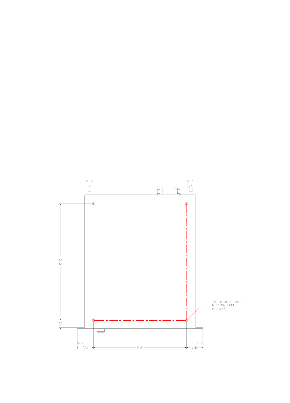
Lake Shore Model 642 Electromagnet Power Supply User’s Manual
3-12 Installation
3.12 DETACHABLE HANDLES
The Model 642 is supplied with 4 detachable handles to enable handling. The handles should normally remain attached
to the unit. However, in some cases it may be necessary to remove the handles to enable mounting in an equipment rack.
In this case, handles may be removed but they should be stored in the rack with the power supply so that they may be
reattached if the unit must be returned for service. Heavy duty handles have been installed to carry the weight of the
power supply. No substitutions should be made. Light duty handles may fail when moving the supply causing the risk of
injury to personnel and damage to equipment.
3.13 RACK MOUNTING
The Model 642 can be installed in a standard 19-inch rack mount cabinet and requires 311 mm (12.25 in) (7U) in height.
At least 25 mm (1 in) of space should be provided on each side for cross ventilation. No ventilation panels are required
above or below the unit. Due to the weight of the power supply, it is recommended that the supply be located at the
bottom of the rack and that it rest on the bottom panel of the rack. If the rack does not have a bottom panel, a shelf,
capable of supporting 74 kg (163 lb) must be provided. Light duty support rails, which bolt to the sides of the front and
rear mounting rails of the rack are not strong enough to support this unit.
In addition, if the equipment rack which houses the Model 642 is to be shipped, the Model 642 must be anchored to the
shelf. Threaded inserts are provided in the bottom of the Model 642 for this purpose. Four (4) ¼-20 × ½ in bolts (not
included) are required. The hole pattern for mounting is shown in Figure 3.16.
CAUTION: The front panel rack mount is to be used only to secure the power supply to the front of the rack.
The bottom of the rack or the equipment shelf must support the entire weight of the supply. Do NOT
attempt to support the supply from the front mounting holes alone.
Figure 3-16. Mounting Hole Pattern
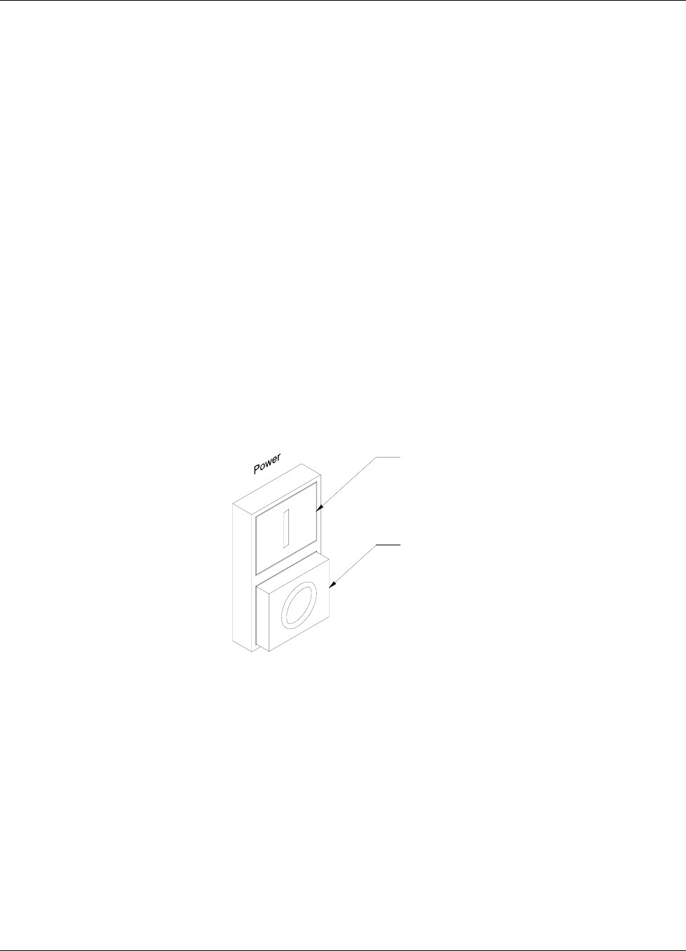
Lake Shore Model 642 Electromagnet Power Supply User’s Manual
Operation 4-1
CHAPTER 4
OPERATION
4.0 GENERAL
This chapter provides operating instructions for the features of the Model 642 Electromagnet Power Supply. Computer
interface instructions are in Chapter 5.
4.1 TURNING POWER ON
Verify that the AC line voltage indicator on the rear panel of the unit shows the appropriate AC line voltage before
turning the instrument on. The instrument may be damaged if it is turned on with the incorrect voltage selected.
Instructions for checking line voltage selection are given in Paragraph 3.3.1.
CAUTION: Be sure the unit is connected to an appropriate load before applying power.
Note: The Model 642 will not turn on if an Emergency Stop Switch is not connected or a jumper is not put in its
place on the “Auxiliary” connector at the rear of the unit. The unit will not turn on if it is connected to a
voltage source more than 10% greater than the voltage for which it is configured.
The power ON and OFF buttons are located in the lower left corner of the front panel. Press the ON button to energize
the Model 642. The Model 642 can be de-energized by pressing the OFF button, by pressing an optional remote
Emergency Stop button, or by the Model 642 software when a hazardous fault condition is detected. The ON and OFF
buttons are illustrated in Figure 4-1.
POWER "ON" BUTTON
POWER "OFF" BUTTON
Figure 4-1. Model 642 Power Push Buttons
When the Model 642 is turned on, the display shows the Lake Shore logo and the alarm beeper sounds briefly. After a
few seconds, a “Checking Hardware” message will appear in the center of the logo display while the instrument does an
internal diagnostic and makes sure everything is working. Most of the instrument setup parameter values are retained
when power is off with a few exceptions. The output current will always be set to 0 A anytime the instrument is powered
up. When the instrument is powered on for the first time, parameter values are set to their defaults, as listed in Table 4-3.
When initialization is complete, the instrument will begin its normal reading cycle. Current and voltage readings should
appear on the display. Any error messages will appear in the center of the display. Messages listed in Table 7-2,
Instrument Hardware Errors, are related to the instrument hardware and may require help from Lake Shore service. The
messages listed in Table 7-3, Operational Errors, are related to instrument operation and may be corrected with user
intervention.
The Model 642 should be allowed to warm up for a minimum of 30 minutes to achieve rated accuracy.
Lake Shore Model 642 Electromagnet Power Supply User’s Manual
4-2 Operation
4.2 DISPLAY DEFINITION
The Model 642 has an 8 line by 40 character vacuum fluorescent (VF) display capable of showing both text and graphic
images. The features displayed during normal operation include current measurement, voltage measurement, current
programming, ramp rate, magnet water status, internal water status, program mode, and internal temperature. Other
display configurations appear during parameter setting and data entry operations. These displays are illustrated in their
individual operation paragraphs. A typical display is shown below.
Output I Output V
+70.0000 A +35.000 V
Set: +70.0000 A Rate:0.0001 A/s
Magnet Water: Off Pgm Mode: Internal
Int Water: Off Int Temp: 27.5 ±C
4.3 LED ANNUNCIATORS
There are five LED annunciators on the front panel that are used to indicate the status of the instrument. These provide
easy verification of the operation of the instrument. See Figure 4-2 for LED locations.
Table 4-1. Model 642 LED Descriptions
Fault On when a hardware fault condition exists, blinking when a soft fault condition exists.
Compliance On when maximum compliance voltage is reached.
Power Limit On when power in internal devices reaches the maximum limit.
Ramping On when output current is ramping, blinking when ramp is paused.
Remote On when instrument is in remote computer interface mode.
4.3.1 Fault LED
The Fault LED will light whenever an error condition is encountered. It may also be accompanied by an alarm depending
on the fault. (Refer to Table 7-2 Instrument Hardware Errors, and Table 7-3 Operational Errors.)
4.3.2 Compliance LED
The Compliance LED lights whenever the maximum output voltage is reached. This can happen when attempting to
rapidly ramp a magnet with higher than usual voltage required to overcome the magnet’s inductance. The led will go out
when the condition clears.
4.3.3 Power Limit LED
The Model 642 has a hardware power limit to protect the internal power MOSFETs. If the power supply is driving a load
which has a resistance lower than the supply’s rated minimum, the power required may be higher than the devices can
safely handle. If this happens, the power in the devices is prevented from exceeding the safe limit and the Power Limit
LED will light to alert the operator to the condition. The led will go out when the condition clears.
4.3.4 Ramping LED
The Ramping LED lights whenever the internal control circuitry is changing the output current. When the ramp is
completed and the current is at the desired point, the LED goes out. The LED does not light when the output current is
being controlled by an external source.
4.3.5 Remote LED
The Remote LED is lit when the Remote key has been pressed to accept remote computer programming input, or upon
receiving the first command over the IEEE bus. When the LED is lit, the main keypad is locked out. Pressing the Local
key will return the unit to the local mode and reestablish keypad functions.
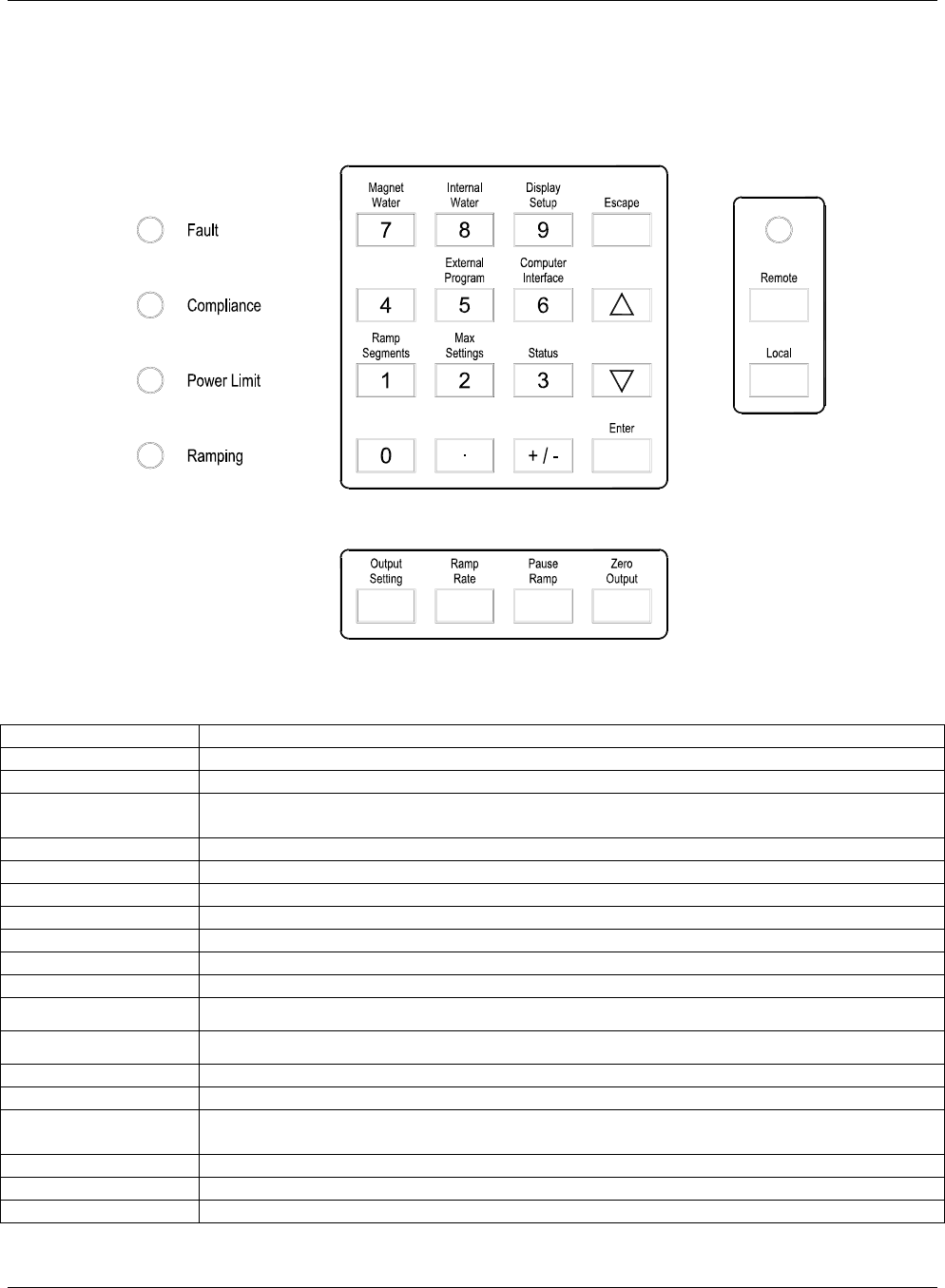
Lake Shore Model 642 Electromagnet Power Supply User’s Manual
Operation 4-3
4.4 KEYPAD DEFINITION
The Model 642 has 22 keys separated into 3 groups on the instrument front panel. The sixteen keys in the center of the
grouping combines instrument setup and data entry. The keys below control the output current and ramping. The keys to
the right control the computer interface mode of the instrument. See Figure 4-2 for key locations. Refer to Table 4-2 for
keypad descriptions.
Figure 4-2. Model 642 Keypad and LED Layout
Table 4-2. Model 642 Key Descriptions
Magnet Water Selects the magnet water setup menu. Refer to Paragraph 4.12.
Internal Water Selects the internal water setup menu. Refer to Paragraph 4.13.
Display Setup Sets the display brightness. Refer to Paragraph 4.5.
Escape Exits from parameter setting sequence without changing the parameter value. Press and hold to
reset parameters to default values. Refer to Paragraph 4.18.
External Program Setup the external current programming mode. Refer to Paragraph 4.15.
Computer Interface Setup RS-232C and IEEE-488 computer interfaces. Refer to Paragraph 4.17.
Ramp Segments Setup ramp segment values. Refer to Paragraph 4.8.
Max Settings Setup maximum setting limits for output current, and ramp rate. Refer to Paragraph 4.11.
Status Displays a summary of the instrument status. Refer to Paragraph 4.14.
Enter Accepts a new parameter value. Press and hold to lock keypad. Refer to Paragraph 4.16.
0-9, ±, . Numeric data entry within a setting sequence.
H (Up) Increments a parameter selection or value.
I (Down) Decrements a parameter selection or value.
Output Setting Sets the output current. Refer to Paragraph 4.6.
Ramp Rate Sets the output current ramp rate. Refer to Paragraph 4.7.
Pause Ramp Pauses the output ramp and holds the current where it was pause pressed. Press again to
continue ramp. Refer to Paragraph 4.9.
Zero Output Ramps the current to 0 A at the programmed ramp rate. Refer to Paragraph 4.10.
Remote Places the instrument to Remote mode. Refer to Paragraph 5.1.2.
Local Returns the instrument to Local mode if in Remote. Refer to Paragraph 5.1.2.

Lake Shore Model 642 Electromagnet Power Supply User’s Manual
4-4 Operation
4.4.1 General Keypad Operation
The Model 642 uses three basic keypad operations, direct operation, setting selection, and data entry, for the majority of
operator interface. A few specialized keypad operations, such as ramp segment entry, are described in the individual
operation paragraphs.
Direct Operation: Key functions occur immediately when the key is pressed. Pause Ramp and Zero Output and are
examples of keys that operate this way.
Setting Selection: Allows the user to select from a finite list of parameter values. During setting selection the H and I
keys are used to select a parameter value. Enter is used to accept the change and advance to the next parameter. Escape
will cancel the change to that parameter and return to the normal display. Setting selection screens always include the
message: “Select with HI”.
Data Entry: Allows the user to enter numeric parameter values using the data entry keys that are printed on the key tops.
Data entry keys include numbers from 0 to 9, ± sign, and decimal point. The labels printed above the keys describe the
key function during normal operation. When one of the keys is pressed and a data entry sequence is started, the keys
follow the data entry functions printed on the key tops. Once the correct parameter value is entered, press Enter to
accept the change and advance to next parameter. Pressing Escape once will clear the new value and restart the setting
sequence. Pressing Escape again will return to the normal display. Data entry screens always include the message:
“Enter a value for”.
Related setting selection and data entry sequences are often chained together under a single key. To skip over a
parameter without changing its value, press Enter before pressing an arrow or number key. To return to the normal
display in the middle of a setting sequence, press Escape before pressing an arrow or number key. Changes entered
before Escape is pressed are kept.
4.5 DISPLAY SETUP
The Display Setup allows the user to set the display brightness. The vacuum fluorescent (VF) display on the Model 642
has four brightness settings between 25% and 100% that can be changed from the front panel. The brightness setting
changes the entire VF display but does not affect the LED annunciators to the right of the display. Continuous use of the
instrument at 100% brightness will reduce the operating life of the display and brightness of 25%, the default setting, is
recommended for most applications. To change the display brightness, press Display Setup and the brightness setup will
appear.
Display Setup
Select With °®
Brightness: 25 %
Use the s or t key to select brightness, 25%, 50%, 75%, or 100%. Press Enter to accept the new selection and return
to the normal display. Press Escape to cancel the new selection and return to the normal display.
4.6 SETTING OUTPUT CURRENT
The main purpose of the Model 642 Electromagnet Power Supply is to supply a very precise and stable current to a
magnet load. Before setting output current, make sure that the instrument is properly setup for the magnet system
that is being used. This includes setting up the maximum output current and maximum ramp rate. When a new output
current setting is entered, the supply will ramp to the new setting at the current ramp rate, unless limited by the fixed
compliance voltage. The Ramping LED will be lit while the output current is ramping. When the output current setting is
entered, it will be limited in magnitude by the maximum current setting. Refer to Paragraph 4.11 to setup the maximum
settings.
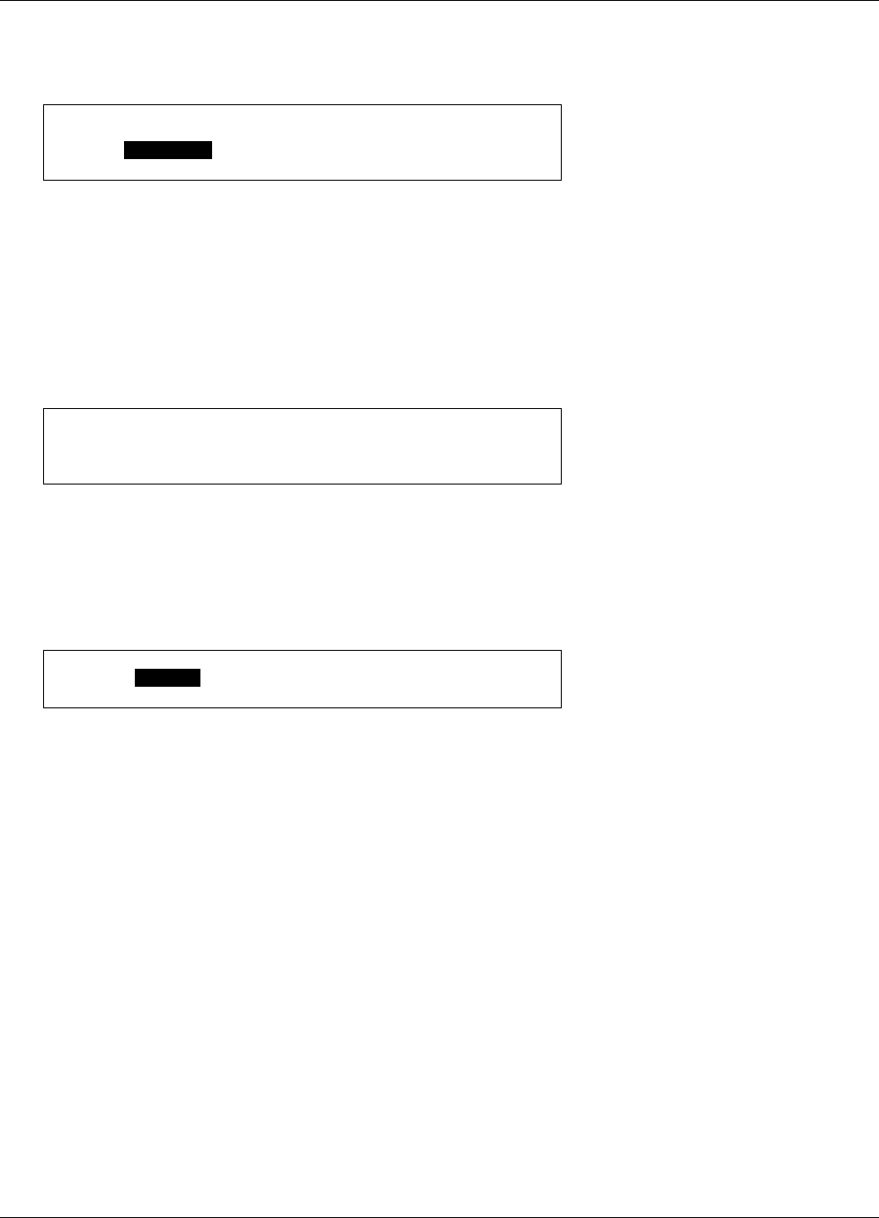
Lake Shore Model 642 Electromagnet Power Supply User’s Manual
Operation 4-5
Setting Output Current (Continued)
To change the output current setting, press the Output Setting key. The output current setting value on the normal
display will be highlighted to prompt for the new output current setting value.
Set: + 0.0000 A
Use the data entry keys to enter an output current setting value between –70.0000 and + 70.0000. Press Enter to accept
the new value. Press Escape to restart the setting sequence and enter a different value. Press Escape again to leave the
setting sequence.
NOTE: The output current setting value can be set as high as ±70.1000 A. This can be used to compensate for variances
in calibration. The output current is guaranteed to reach a minimum of 70 A into a 0.5 ohm load but may not be
able to reach 70.1 A in all circumstances.
The output current setting is not allowed to change if the instrument is setup so that the output current is programmed
solely by an external voltage. Refer to Paragraph 4.15 to setup the external current program mode.
Change not allowed while
in external current program mode
4.7 CURRENT RAMP RATE
The output current of the Model 642 will always ramp from one current setting to another. There is no way to turn off the
current ramping function, but if a very fast ramp rate is desired, a ramp rate as high as 99.999 A/s can be entered.
To change the current ramp rate press the Ramp Rate key. The ramp rate value on the normal display will be
highlighted to prompt for the new ramp rate value.
Rate: 1.0000 A/s
Use the data entry keys to enter the ramp rate value between 0.0001 and 99.999 A/s. Press Enter to accept the new
value. Press Escape to restart the setting sequence and enter a different value. Press Escape again to leave the setting
sequence.
4.8 RAMP SEGMENTS
The magnetic field produced by electromagnets is not linear with current setting. The best way to compensate for this is
to use closed loop field control but if absolute accuracy is not necessary than some of this nonlinearity can be corrected
by the use of the ramp segments feature. The ramp segments feature can be used to increase the current ramp rate as the
magnet saturates in an attempt to maintain the same field ramp rate. This feature can change the output current ramp rate
based on the output current setting. As the output setting ramps through the segment boundary, the new ramp rate will be
used although it will still be limited by the maximum ramp rate setting. Refer to Paragraph 4.11.2 to set the maximum
ramp rate.
To use the ramp segment feature, the ramp segments must be enabled and the ramp segment table must be setup to
specify which ramp rate to use for each current setting. The table should be setup in order of increasing current.
A current entry of 0 A indicates the end of the table and the instrument will not search any higher in the table.

Lake Shore Model 642 Electromagnet Power Supply User’s Manual
4-6 Operation
Ramp Segments (Continued)
To configure the ramp segments press Ramp Segments. The first ramp segments setup screen appears as a prompt for
the ramp segments mode.
Ramp Segments
Select With °®
Ramp Segments: Enable
Use the s or t key to select the ramp segments mode, either Enable or Disable. Press Enter to accept the new selection
and continue to the next setting screen. Press Escape to cancel the new selection and return to the normal display.
If the ramp segments are enabled, the next ramp segments screen that appears is for entering or editing the ramp
segments table. All five of the ramp segments are shown on the display at the same time. The segments should be
entered in order of increasing current. An entry of 0 A will indicate the end of the table and the instrument will not
search beyond that segment.
Ramp Segments
Current Ramp Rate
1: 10.0000 A 1.0000 A/s
2: 15.0000 A 0.8000 A/s
3: 20.0000 A 0.7000 A/s
4: 30.0000 A 0.6000 A/s
5: 40.0000 A 0.5000 A/s
When the segment number is highlighted, use the s or t key to scroll through the ramp segments. Press the Enter key
when the desired segment number is highlighted and continue to the current field.
When the current field is highlighted, use the numerical keypad to enter the upper current setting for that ramp segment
in amps. Press Enter to accept the new selection and continue to the ramp rate field. Press Escape to restart the setting
sequence and enter a new value. Press Escape again to highlight the segment number.
When the ramp rate field is highlighted, use numerical keypad to enter the applicable ramp rate in A/s. Press Enter to
accept the new selection and continue to the next segment. Press Escape to restart the setting sequence and enter a new
value. Press Escape again to highlight the segment number.
Similarly enter or edit all ramp segments. When complete, press the Escape key while the segment number field is
highlighted to exit the ramp segment edit screen and return to the normal display. When output current is called for using
the Output Setting key, the output will ramp to the desired current using the ramp segment set points.
4.9 PAUSE RAMP
The Pause Ramp key will pause the output current ramp within two seconds after the key is pressed. While the output
current ramp is paused, the Ramping LED will blink. Pressing the Pause Ramp key again will continue the ramping.
Pressing the Enter key while the ramp is paused will set the current at the paused setting and exit the Pause Ramp
mode.
4.10 ZERO OUTPUT
The Zero Output key on the front panel can be used to set the output current to 0 A. When the Zero Output key is
pressed, the current output will begin to ramp down using the current ramp rate. This key is equivalent to using the
Output Setting key and entering 0 A except that it works even when the Model 642 is being programmed externally.
Refer to Paragraph 4.6 to set the output current.
NOTE: The current ramp rate applies only to the internal current output setting. When the Model 642 is
programmed externally, the drop to zero output (when the Zero Output key is pressed) will be quite rapid
(~1 second) and limited primarily by the magnet reactance and the Model 642 voltage compliance limit.
The voltage compliance LED may light during the change.

Lake Shore Model 642 Electromagnet Power Supply User’s Manual
Operation 4-7
4.11 MAXIMUM SETTING LIMITS
The Model 642 offers a maximum setting limit for output current and ramp rate. Typical properties of the magnet will
dictate these parameters. These maximum parameters should be entered before the magnet system is used to prevent
damage.
4.11.1 Maximum Output Current
Maximum Output Current limits the output current that can be entered. This setting will only limit the internal output
current setting. If the output current is being programmed by an external voltage, then some external provision must be
made to insure that the programming voltage will never exceed the desired output current. See Paragraph 4.15 to setup
the External Current Programming mode.
To set the maximum output current limit press Max Settings. The first maximum setting screen appears as a prompt for
the maximum output current limit.
Maximum Settings
Enter a Value For
Max Current: 60.0000 A
Use the data entry keys to enter the maximum output current limit value between 0.0000 and 70.0000 A. Press Enter to
accept the new value. Press Escape to restart the setting sequence and enter a different value. Press Escape again to
leave the setting sequence.
NOTE: The maximum output current limit value can be set as high as 70.1000 A. This can be used to compensate
for variances in calibration. The output current is guaranteed to reach a minimum of 70 A into a 0.5-ohm
load but may not be able to reach 70.1 A in all circumstances.
4.11.2 Maximum Current Ramp Rate
Maximum Current Ramp Rate limits the maximum current ramp rate that can be entered. This setting will only limit the
internal output current ramp setting. If ramp segments are being used, this setting will also limit the ramp rate that can be
set by a ramp segment. Refer to Paragraph 4.8 to setup Ramp Segments.
To enter a value for the maximum current ramp rate limit, continue from the maximum current screen or press Max
Settings then Enter until the following display setup screen appears as a prompt for the maximum current ramp rate
limit.
Use the data entry keys to enter the maximum current ramp rate limit value between 0.0001 and 99.999 A/s. Press Enter
to accept the new value. Press Escape to restart the setting sequence and enter a different value. Press Escape again to
leave the setting sequence.
Maximum Settings
Enter a Value For
Max Ramp Rate: 1.0000 A/s

Lake Shore Model 642 Electromagnet Power Supply User’s Manual
4-8 Operation
4.12 MAGNET WATER
The Model 642 provides power to control an external magnet water solenoid control valve. The setup of the valve
control is available in the Magnet Water menu. The four menu selections are Auto, On, Off, and Disabled, with Auto
being the default setting.
In the Auto mode, the water valve will be energized when the power in the magnet exceeds 100 W. When the power
drops below 100 W, the valve will remain energized for an additional minute to remove any residual heat build-up.
In the On mode, the valve will be energized whenever the power supply is on. This feature can be used when the system
is first installed to purge air from the water lines and magnet. It can also be used to turn on the water in advance of a test
to bring the magnet temperature to equilibrium. The Off menu selection can be used to turn it off.
In the Disabled mode, the Model 642 assumes that no valve is installed and the line for Magnet Water status will not be
displayed.
The magnet water flow switch is monitored whenever the water valve is energized. It is also monitored continuously
when in Disabled mode to allow the use of a flow switch even when no water valve is used. If no flow switch or water
valve is present, then a jumper must be installed across the flow switch contacts for proper operation.
4.13 INTERNAL WATER
The Model 642 provides power to control an external water solenoid control valve to control the cooling water for the
power supply. The setup of the valve control is available in the Internal Water menu. The four menu selections are
Auto, On, Off, and Disabled, with Disabled being the default setting.
In the Auto mode, the water valve will be energized when the power in the internal power devices exceeds 100 W. When
the power drops below 100 W, the valve will remain energized for an additional minute to remove any residual heat
build-up.
In the On mode, the valve will be energized whenever the power supply is on. This feature can also be used when the
Model 642 is first installed to purge air from the lines. The Off menu selection can be used to turn it off.
In the Disabled mode, the Model 642 assumes that no valve is installed and the line for Internal Water status will not be
displayed.
The internal water flow switch is monitored whenever the water valve is energized. It is also monitored continuously
when in Disabled mode to allow the use of a flow switch even when no water valve is used. If no flow switch or water
valve is present, then a jumper must be installed across the flow switch contacts for proper operation.
4.14 ERROR STATUS DISPLAY
Error messages appear in the center of the instrument display when a problem is identified during operation. The Fault
LED will also light to indicate error conditions, blinking for operational errors, on continuously for instrument hardware
errors. Refer to Paragraph 7.6 for a listing of all the error conditions. When an error condition occurs, the name of the
error is shown in the display alternately with “Press Status Key for More Info.” Pressing the Status key will bring up a
screen that will show an extended description of the error.
To enter the error status display press Status while in the main display. A screen similar to the one shown below
appears. This screen will differ depending on the error that is being displayed. If there are no errors to report, the display
will show “No errors reported.” The following example shows the description for “External Current Program Error”.
Cannot set external current program mode.
Set programming voltage to 0 V or change to
internal program mode.

Lake Shore Model 642 Electromagnet Power Supply User’s Manual
Operation 4-9
4.15 EXTERNAL CURRENT PROGRAMMING
The output current of the Model 642 can be set internally, externally, or by the sum of the external and internal settings.
Normally, the current is controlled internally by entering a setting from the front panel using the Output Setting key.
Refer to Paragraph 4.6 to set the output current. When the external program mode is set to External, the front panel
setting is fixed at 0 A and the output current is set using an external voltage where 10 V = 70 A. When the external
program mode is set to Sum, the internal and external settings are summed together to set the output current. When using
the External or Sum modes, care must be taken to insure that the output current does not exceed the maximum current for
the magnet. The software maximum setting limits cannot limit the output current or ramp rate that is set when using the
External or Sum modes. A –3 dB, 40 Hz, two-pole, low-pass filter limits the bandwidth of the external current
programming input. The bandwidth of the output is also limited by the compliance voltage and the inductance of the
magnet. To configure the external current program mode press External Program. The following setup screen appears
as a prompt for the external current program mode.
External Program Mode
Select With °®
External Program Mode: Internal
Use the s or t key to select the external current program mode, Internal, External, or Sum. Press Enter to accept the
new selection and return to the normal display. Press Escape to cancel the new selection and return to the normal
display.
To avoid discontinuities in the output current, the external current programming mode cannot be changed if the
programming voltage is not zero or the front panel current setting is not zero. If the external current program mode is
going to be kept from changing, an error box will pop up explaining why the new setting is being ignored. This error box
is shown below.
Change not allowed while
programming voltage is not zero.
4.16 LOCKING THE KEYPAD
The keypad lock feature prevents accidental changes to parameter values. When the keypad is locked, parameter values
may be viewed but cannot be changed from the front panel. The Model 642 has two keypad lock modes. The lock all
mode locks out changes to all parameters. The lock limits mode locks out changes to all of the parameters except Output
Setting, Ramp Rate, Zero Output and Pause Ramp. This allows the power supply to be operated without allowing any
changes to the power supply setup.
A 3-digit code must be used to lock and unlock the keypad. The factory default code is 123 and it can only be changed
using a computer interface. If the instrument parameters are reset to default values (See Default Parameter Values 4.18),
the code is reset to the factory default. The instrument parameters cannot be reset to default values from the front panel
when the keypad is locked.
The following message box appears on the display if the user attempts to change a parameter while the keypad is locked.
Change not allowed while
keypad is locked.
NOTE: The computer interface has a remote operation mode that may be mistaken for a locked keypad. If the front
panel Remote LED is lit, press the Local key to change to local control of the instrument.

Lake Shore Model 642 Electromagnet Power Supply User’s Manual
4-10 Operation
Locking the Keypad (Continued)
To lock or unlock the instrument keypad press and hold the Enter key for 5 seconds. The following setup screen appears
as a prompt for the keypad lock mode.
Keypad Lock
Select With °®
Keypad Lock: Unlock
Use the s or t key to select the keypad lock mode, Unlock, Lock All, or Lock Limits. Press Enter to choose the new
selection and continue to the keypad lock code verification. The change to the keypad lock mode is not made until the
correct keypad lock code has been entered. Press Escape to cancel the new selection and return to the normal display.
Once the keypad lock mode has been selected, the keypad lock code must be entered to accept the change. The following
screen appears as a prompt for the keypad lock code.
Keypad Lock
Enter A Value For
Keypad Lock Code:
Use the data entry keys to enter the 3-digit lock code (default 123). An asterisk will appear on the display for each
number entered. If the code entered matches the lock code, the display will show “Change Accepted” and the
keypad lock mode will be updated. If the code entered does not match the lock code, the display will show
“Invalid Lock Code” and the keypad lock mode will not change.
4.17 COMPUTER INTERFACE
There are two computer interfaces on the Model 642, a serial RS-232C interface and an IEEE-488 interface. These
interfaces are used to connect the instrument to a computer for automated control or data taking. Refer to Chapter 5.
4.17.1 Changing Serial Baud Rate
To select the Serial Interface Baud Rate press the Computer Interface key. The first computer interface screen appears
as a prompt for Baud.
Computer Interface
Select With °®
Baud: 9600
Use the s or t key to select 9600, 19200, 38400, or 57600 Baud. Default is 9600 Baud. Press Enter to accept the new
selection and continue to the next screen. Press Escape to cancel the new selection and return to the normal display.

Lake Shore Model 642 Electromagnet Power Supply User’s Manual
Operation 4-11
4.17.2 Changing IEEE-488 Interface Parameters
Two interface parameters, address and terminators, must be set from the front panel before IEEE-488 communication
with the instrument can be established. Other interface parameters can be set via the interface using the device specific
commands provided in Paragraph 5.3.
To set the IEEE-488 parameters, press the Computer Interface key and press Enter to skip past Serial Interface Baud
Rate. The following computer interface screen appears as a prompt for the IEEE-488 address.
Computer Interface
Select With °®
IEEE Address: 12
Use the s or t key to select an address between 1 and 30. The default is twelve. Press Enter to accept the new
selection and continue to the next setting screen. Press Escape to cancel the new selection and return to the normal
display. The next computer interface screen appears as a prompt for the IEEE-488 terminators.
Computer Interface
Select With °®
IEEE Term: Cr Lf
Use the s or t key to select one of the following terminators: CR/LF, LF/CR, LF, and EOI. The default is CR/LF.
Press Enter to accept the new selection and continue to the next setting screen. Press Escape to cancel the new selection
and return to the normal display.
4.18 DEFAULT PARAMETER VALUES
It is sometimes desirable to reset instrument parameters to their default values. This data is stored in nonvolatile memory
called EEPROM. Instrument calibration is not affected by this operation. Firmware version information for the main
firmware and the DAC firmware is also displayed during this sequence.
To clear EEPROM memory or view the firmware versions press and hold the Escape key for 5 seconds. The following
screen appears to show the main firmware version, the DAC processor firmware version, and as a prompt for returning
the instrument parameters to default values. Default parameter values are listed in Table 4-3.
Main Code Version: 1.0
DAC Code Version: 1.0
Select With °®
Default Values: No
Use the s or t key to select Yes for default values and No to continue without changing the parameter values. Press
Enter to accept the new selection and return to the normal display. Press Escape to cancel the new selection and return
to the normal display.

Lake Shore Model 642 Electromagnet Power Supply User’s Manual
4-12 Operation
Table 4-3. Default Parameter Values
Output Settings
Output Current* .....................................0 A
Current Ramp Rate..................... 99.999 A/s
Maximum Settings
Max Output Current..........................70.1 A
Max Ramp Rate......................... 99.999 A/s
External Program Mode
External Program Mode.................. Internal
Ramp Segments
Ramp Segments .............................Disabled
Ramp Segments Current ........................0 A
Ramp Segments Rate ................. 1.0000 A/s
Display
Brightness ..............................................25%
Keypad Locking
State............................................... Unlocked
Lock Code............................................... 123
Computer Interface
Baud...................................................... 9600
IEEE-488 Address .................................... 12
IEEE-488 Terminators.......................CR/LF
Mode*.................................................. Local
Water Settings
Magnet Water................................ Disabled
Internal Water ............................... Disabled
* Indicates value is also initialized on power up

Lake Shore Model 642 Electromagnet Power Supply User’s Manual
Computer Interface Operation 5-1
CHAPTER 5
COMPUTER INTERFACE OPERATION
5.0 GENERAL
This chapter provides operational instructions for the computer interface for the Lake Shore Model 642 Electromagnet
Power Supply. Either of the two computer interfaces provided with the Model 642 permit remote operation. The first is
the IEEE-488 Interface described in Paragraph 5.1. The second is the Serial Interface described in Paragraph 5.2. The
two interfaces share a common set of commands detailed in Paragraph 5.3. Only one interface can be used at a time.
5.1 IEEE-488 INTERFACE
The IEEE-488 Interface is an instrumentation bus with hardware and programming standards that simplify instrument
interfacing. The Model 642 IEEE-488 Interface complies with the IEEE-488.2-1987 standard and incorporates its
functional, electrical, and mechanical specifications unless otherwise specified in this manual.
All instruments on the interface bus perform one or more of the interface functions of TALKER, LISTENER, or BUS
CONTROLLER. A TALKER transmits data onto the bus to other devices. A LISTENER receives data from other
devices through the bus. The BUS CONTROLLER designates to the devices on the bus which function to perform.
The Model 642 performs the functions of TALKER and LISTENER but cannot be a BUS CONTROLLER. The BUS
CONTROLLER is the digital computer which tells the Model 642 which functions to perform.
Below are Model 642 IEEE-488 interface capabilities:
• SH1: Source handshake capability.
• RL1: Complete remote/local capability.
• DC1: Full device clear capability.
• DT0: No device trigger capability.
• C0: No system controller capability.
• T5: Basic TALKER, serial poll capability, talk only, unaddressed to talk if addressed to listen.
• L4: Basic LISTENER, unaddressed to listen if addressed to talk.
• SR1: Service request capability.
• AH1: Acceptor handshake capability.
• PP0: No parallel poll capability.
• E1: Open collector electronics.
Instruments are connected to the IEEE-488 bus by a 24-conductor connector cable as specified by the standard. Refer to
Paragraph 7.12.2. Cables can be purchased from Lake Shore or other electronic suppliers.
Cable lengths are limited to 2 meters for each device and 20 meters for the entire bus. The Model 642 can drive a bus
with up to 10 loads. If more instruments or cable length is required, a bus expander must be used.

Lake Shore Model 642 Electromagnet Power Supply User’s Manual
5-2 Computer Interface Operation
5.1.1 Changing IEEE-488 Interface Parameters
Two interface parameters, address and terminators, must be set from the front panel before communication with the
instrument can be established. Other interface parameters can be set via the interface using the device specific commands
provided in Paragraph 5.3.
To set the IEEE-488 parameters, press the Computer Interface key and press Enter to skip past Serial Interface Baud
Rate. The following computer interface screen appears as a prompt for the IEEE-488 address.
Computer Interface
Select With °®
IEEE Address: 12
Use the s or t key to select an address between 1 and 30. The default is twelve. Press Enter to accept the new
selection and continue to the next setting screen. Press Escape to cancel the new selection and return to the normal
display. The next computer interface screen appears as a prompt for the IEEE-488 terminators.
Computer Interface
Select With °®
IEEE Term: Cr Lf
Use the s or t key to select one of the following terminators: CR/LF, LF/CR, LF, and EOI. The default is Cr/Lf. Press
Enter to accept the new selection and continue to the next setting screen. Press Escape to cancel the new selection and
return to the normal display.
5.1.2 Remote/Local Operation
Normal operations from the keypad are referred to as ‘Local’ operations. The Model 642 can also be configured for
‘Remote’ operations via the IEEE-488 interface or the Remote key. The Local key will take the instrument out of
‘Remote’ operation and place it in ‘Local’ operation. During ‘Remote’ operations, the Remote LED annunciator will be
illuminated and operations from the keypad will be disabled.
5.1.3 IEEE-488 Command Structure
The Model 642 supports several command types. These commands are divided into three groups.
1. Bus Control – Refer to Paragraph 5.1.3.1.
a. Universal
(1) Uniline
(2) Multiline
b. Addressed Bus Control
2. Common – Refer to Paragraph 5.1.3.2.
3. Device Specific – Refer to Paragraph 5.1.3.3.
4. Message Strings – Refer to Paragraph 5.1.3.4.

Lake Shore Model 642 Electromagnet Power Supply User’s Manual
Computer Interface Operation 5-3
5.1.3.1 Bus Control Commands
A Universal Command addresses all devices on the bus. Universal Commands include Uniline and Multiline Commands.
A Uniline Command (Message) asserts only a single signal line. The Model 642 recognizes two of these messages from
the BUS CONTROLLER: Remote (REN) and Interface Clear (IFC). The Model 642 sends one Uniline Command:
Service Request (SRQ).
REN (Remote) – Puts the Model 642 into remote mode.
IFC (Interface Clear) – Stops current operation on the bus.
SRQ (Service Request) – Tells the bus controller that the Model 642 needs interface service.
A Multiline Command asserts a group of signal lines. All devices equipped to implement such commands do so
simultaneously upon command transmission. These commands transmit with the Attention (ATN) line asserted low.
The Model 642 recognizes two Multiline commands:
LLO (Local Lockout) – Prevents the use of instrument front panel controls.
DCL (Device Clear) – Clears Model 642 interface activity and puts it into a bus idle state.
Finally, Addressed Bus Control Commands are Multiline commands that must include the Model 642 listen address
before the instrument responds. Only the addressed device responds to these commands. The Model 642 recognizes four
of the Addressed Bus Control Commands:
SDC (Selective Device Clear) – The SDC command performs essentially the same function as the DCL command
except that only the addressed device responds.
GTL (Go To Local) – The GTL command is used to remove instruments from the remote mode. With some
instruments, GTL also unlocks front panel controls if they were previously locked out with the LLO command.
SPE (Serial Poll Enable) and SPD (Serial Poll Disable) – Serial polling accesses the Service Request Status Byte
Register. This status register contains important operational information from the unit requesting service. The SPD
command ends the polling sequence.
5.1.3.2 Common Commands
Common Commands are addressed commands which create commonalty between instruments on the bus. All
instruments that comply with the IEEE-488 1987 standard share these commands and their format. Common commands
all begin with an asterisk. They generally relate to “bus” and “instrument” status and identification. Common query
commands end with a question mark (?). Model 642 common commands are detailed in Paragraph 5.3 and summarized
in Table 5-8.
5.1.3.3 Device Specific Commands
Device specific commands are addressed commands. The Model 642 supports a variety of device specific commands to
program instruments remotely from a digital computer and to transfer measurements to the computer. Most device
specific commands perform functions also performed from the front panel. Model 642 device specific commands are
detailed in Paragraph 5.3 and summarized in Table 5-8.
5.1.3.4 Message Strings
A message string is a group of characters assembled to perform an interface function. There are three types of message
strings: commands, queries and responses. The computer issues command and query strings through user programs, the
instrument issues responses. Two or more command strings or queries can be chained together in one communication but
they must be separated by a semi-colon (;). The total communication string must not exceed 255 characters in length.
A command string is issued by the computer and instructs the instrument to either perform a function or change a
parameter setting. When a command is issued, the computer is acting as ‘talker’ and the instrument as ‘listener’. The
format is:
<command mnemonic><space><parameter data><terminators>.
Command mnemonics and parameter data necessary for each one is described in Paragraph 5.3. Terminators must be
sent with every message string.

Lake Shore Model 642 Electromagnet Power Supply User’s Manual
5-4 Computer Interface Operation
Message Strings (Continued)
A query string is issued by the computer and instructs the instrument which response to send. Queries are issued similar
to commands with the computer acting as ‘talker’ and the instrument as ‘listener’. The query format is:
<query mnemonic><?><space><parameter data><terminators>.
Query mnemonics are often the same as commands with the addition of a question mark. Parameter data is often
unnecessary when sending queries. Query mnemonics and parameter data if necessary is described in Paragraph 5.3.
Terminators must be sent with every message string. Issuing a query does not initiate a response from the instrument.
A response string is sent by the instrument only when it is addressed as a ‘talker’ and the computer becomes the
‘listener’. The instrument will respond only to the last query it receives. The response can be a reading value, status
report or the present value of a parameter. Response data formats are listed along with the associated queries in
Paragraph 5.3.
5.1.4 Status System
5.1.4.1 Overview
The Model 642 implements a status system compliant to the IEEE 488.2 – 1992 standard. The status system provides a
method of recording and reporting instrument information and is typically used to control the Service Request (SRQ)
interrupt line. A diagram of the status system is shown in Figure 5-1. The status system is made up of register sets, the
Status Byte register and the Service Request Enable register. Each register set consists of three types of registers,
condition, event, and enable,
5.1.4.1.1 Condition Registers
Each register set (except the Standard Event Register set) includes a condition register as shown in Figure 5-1. The
condition register constantly monitors the instrument status. The data bits are real-time and are not latched or buffered.
The register is read-only.
5.1.4.1.2 Event Registers
Each register set includes an event register as shown in Figure 5-1. Bits in the event register correspond to various
system events and latch when the event occurs. When an event bit is set, subsequent events corresponding to that bit are
ignored. Set bits remain latched until the register is cleared by a query command (such as *ESR?) or a *CLS command.
The register is read-only.
5.1.4.1.3 Enable Registers
Each register set includes an enable register as shown in Figure 5-1. An enable register determines which bits in the
corresponding event register will set the summary bit for the register set in the Status Byte. The user may write to or read
from an enable register. Each event register bit is logically ANDed to the corresponding enable bit of the enable register.
When an enable register bit is set by the user, and the corresponding bit is set in the event register, the output (summary)
of the register will be set, which in turn sets the summary bit of the Status Byte register.
5.1.4.1.4 Status Byte Register
The Status Byte register, typically referred to as simply the Status Byte, is a non-latching, read-only register that contains
all of the summary bits from the register sets. The status of the summary bits are controlled from the register sets as
explained above. The Status Byte also contains the Request for Service (RQS)/Master Summary Status (MSS) bit. This
bit is used to control the Service Request hardware line on the bus and to report if any of the summary bits are set via the
*STB? command. The status of the RQS/MSS bit is controlled by the summary bits and the Service Request Enable
Register.
5.1.4.1.5 Service Request Enable Register
The Service Request Enable Register determines which summary bits in the Status Byte will set the RQS/MSS bit of the
Status Byte. The user may write to or read from the Service Request Enable Register. Each Status Byte summary bit is
logically ANDed to the corresponding enable bit of the Service Request Enable Register. When a Service Request
Enable Register bit is set by the user, and the corresponding summary bit is set in the Status Byte, the RQS/MSS bit of
the Status Byte will be set, which in turn sets the Service Request hardware line on the bus.
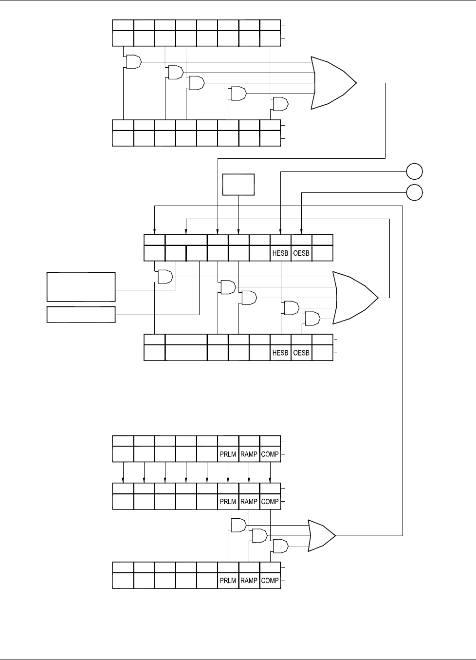
Lake Shore Model 642 Electromagnet Power Supply User’s Manual
Computer Interface Operation 5-5
Service Request
Name
Bit
Not
RQS = Service Request
MSS = Master Summary Status Bit
ESB = Event Status Sumary Bit
MAV = Message Available Summary Bit
OSB = Operation Summary Bit
OESB = Operational Error Summary Bit
HESB = Hardware Error Summary Bit
Used
6
COMP = Compliance
RAMP = Ramp Done
OPSTE?
Register
Operation
Event Enable
OPSTE, Used
Not
7
Used
Not Used
Not
65
Used
Not Not
Used
43
*SRE, *SRE?
Enable Register
Operation
OPSTR?
Condition
OPST?
Operation
Register
Register
Event
Used
7
Not
Used
Not
7
Used
Not
6
Used
5
Not
Not
Used
6
Not
Used
5
Used
4
Not Used
Not
3
Not
Used
4
Not
Used
3
OSB
7
AND
Bit
Name
210
AND
Name
Bit
Name
Bit
Not
Used
2 1
2 1
0
0
ESB
5
MAV
432
Used
1
Not
0
Bit
Name
6
Standard Event
Status Byte
Generate service
request. Reset by
Read by *STB?
PON = Power on
CME = Command Error
EXE = Execution Error
QYE = Query Error
OPC = Operation Complete
RQS
MSS
serial poll.
*ESE, *ESE?
Status Enable
Register
*STB?
AND
OSB
7
RQS
AND
*ESR?
Standard Event
Status Register PON
7
AND
AND
6
Not
Used
5
CME
4
EXE
3
Used
Not
Not
Used
AND
MSS ESB
5
AND
MAV
43
Buffer
Output
2
Used
1
Not
0
Name
Bit
AND
AND
Used
Not
QYE
210
OPC
2 of 2
Sheet
From
A
B
1
Used
Not
7
PON
6
Used
Not Used
Not
EXE
5
CME
4
QYE
2
3
NameOPC
0Bit
OR
AND
OR
PRLM = Power Limit
OR
AND
AND
Figure 5-1. Model 642 Status System (Sheet 1 of 2)
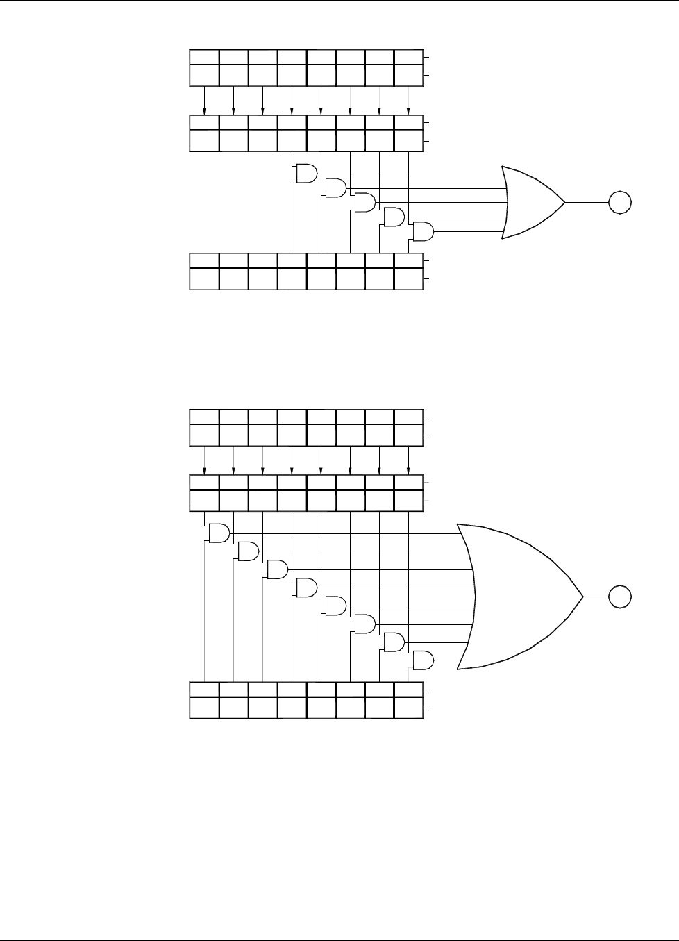
Lake Shore Model 642 Electromagnet Power Supply User’s Manual
5-6 Computer Interface Operation
Name
Name
Name
Used
Not Used
Not
76543210Bit
Used Used
ERST?
Not
Used
7
Not
Used
65
Condition Register
Error Status 7
Not
65
Not
43210Bit
43210Bit
DAC OCFOOV OOCTF
TF
TF
AND
AND
AND
AND
AND
Event Register
Error Status
ERSTR?
Enable Register
Error Status
ERSTE, ERSTE?
ASheet
1 of 2
To
AND
ERSTE, ERSTE?
Enable Register
Error Status
AND
76543
AND
AND
AND
2 1 0Bit
Name
AND
Event Register
ERST?
Error Status
Condition Register
Error Status
ERSTR?
LLV
67 53
4
76
HLVMFF
543
20
1
Name
Bit
EPETH CAL
210
Name
Bit
Sheet
B1 of 2
To
PFFREF
PFFREF HLVMFF LLV EPETH CAL
PFFREF HLVMFF LLV EPETH CAL
AND
AND
OR
Hardware Errors
TF = Temperature Fault
DAC = DAC Processor Not Responding
OCF = Output Control Failure
OOV = Output Over Voltage
OOC = Output Over Current
LLV = Low Line Voltage
Operational Errors
EPE = External Current Program Error
TH = Temperature High
HLV = High Line Voltage
MFF = Magnet Flow Switch Fault
PFF = Power Supply Flow Switch Fault
REF = Remote Enable Fault
CAL = Calibration Error
Used
Not
Used
Not
Used
Not
OR
DAC OCFOOV OOC
DAC OCFOOV OOC
Figure 5-1. Model 642 Status System (Sheet 2 of 2)
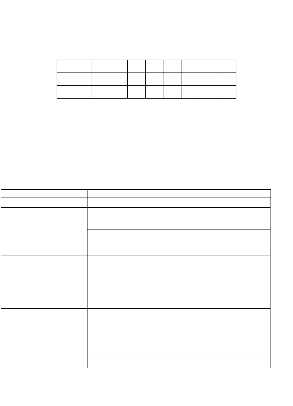
Lake Shore Model 642 Electromagnet Power Supply User’s Manual
Computer Interface Operation 5-7
5.1.4.1.6 Reading Registers
Any register in the status system may be read using the appropriate query command. Some registers clear when read,
others do not. Refer to Paragraph 5.1.4.1.7. The response to a query will be a decimal value that corresponds to the
binary-weighted sum of all bits in the register, Refer to Table 5-1. The actual query commands are described later in
this section.
Table 5-1. Binary Weighting of an 8-Bit Register
Position B7 B6 B5 B4 B3 B2 B1 B0
Decimal 128 64 32 16 8 4 2 1
Weighting 27 2
6 2
5 2
4 2
3 2
2 2
1 2
0
Example: If bits 0, 2, and 4 are set, a query of the register will return a decimal value of 21 (1+4+16).
5.1.4.1.7 Programming Registers
The only registers that may be programmed by the user are the enable registers. All other registers in the status system
are read-only registers. To program an enable register send a decimal value which corresponds to the desired binary-
weighted sum of all bits in the register, Refer to Table 5-1. The actual commands are described later in this section.
5.1.4.1.8 Clearing Registers
The methods to clear each register are detailed in Table 5-2.
Table 5-2. Register Clear Methods
Register Method Example
Condition Registers None – registers are not latched —
Query the event register.
*ESR?
(clears Standard Event
Status register)
Send *CLS *CLS
(clears all three registers)
Event Registers:
Standard Event Status Register
Operation Event Register
Error Status Event Register
Power on instrument —
Write 0 to the enable register.
*ESE 0
(clears Standard Event
Status Enable register)
Enable Registers:
Standard Event Status Enable
Register
Operation Event Enable Register
Error Status Enable Register
Service Request Enable Register
Power on instrument —
There are no commands that directly clear
the Status Byte as the bits are non-
latching. To clear individual summary
bits, clear the event register that
corresponds to the summary bit. Sending
*CLS will clear all event registers which
in turn clears the status byte.
If bit 5 (ESB) of the Status
Byte is set, send *ESR? to
read the Standard Event
Status Register and bit 5
will clear.
Status Byte
Power on instrument —

Lake Shore Model 642 Electromagnet Power Supply User’s Manual
5-8 Computer Interface Operation
5.1.4.2 Status Register Sets
As shown in Figure 5-1, there are five register sets in the status system of the Model 642; Standard Event Status
Register, Operation Event Register, Hardware Error Status Register, Operational Error Status Register, and the Persistent
Switch Error Register.
5.1.4.2.1 Standard Event Status Register Set
The Standard Event Status Register reports the following interface related instrument events: power on detected,
command syntax errors, command execution errors, query errors, operation complete. Any or all of these events may be
reported in the standard event summary bit through the enable register, see Figure 5-2. The Standard Event Status Enable
command (*ESE) programs the enable register and the query command (*ESE?) reads it. *ESR? reads and clears the
Standard Event Status Register. The used bits of the Standard Event Register are described as follows:
Power On (PON), Bit (7) – This bit is set to indicate an instrument off-on transition.
Command Error (CME), Bit (5) – This bit is set if a command error has been detected since the last reading. This
means that the instrument could not interpret the command due to a syntax error, an unrecognized header,
unrecognized terminators, or an unsupported command.
Execution Error (EXE), Bit (4) – This bit is set if an execution error has been detected. This occurs when the
instrument is instructed to do something not within its capabilities.
Query Error (QYE), Bit (2) – This bit indicated a query error. It occurs rarely and involves loss of data because the
output queue is full.
Operation Complete (OPC), Bit (0) – When *OPC is sent, this bit will be set when the instrument has completed all
pending operations. The operation of this bit is not related to the *OPC? command which is a separate interface
feature. Refer to Paragraph 5.1.4.4.6 for more information.
Name
Name
Bit
Bit
AND
CME
5
Not
PON
*ESE, *ESE? Used
Standard Event
Status Enable 76
Not OPC
Not
EXE QYE
Used Used
24 3
AND
10
AND
CME
5
67
Standard Event
*ESR?
Status Register
AND
PON Used
Not
0
1
3
42
QYE
AND
EXE Used
Not Used
Not OPC
OR To bit 5 (ESB) of
Status Byte Register
(See Figure 5-1.)
Figure 5-2. Standard Event Status Register
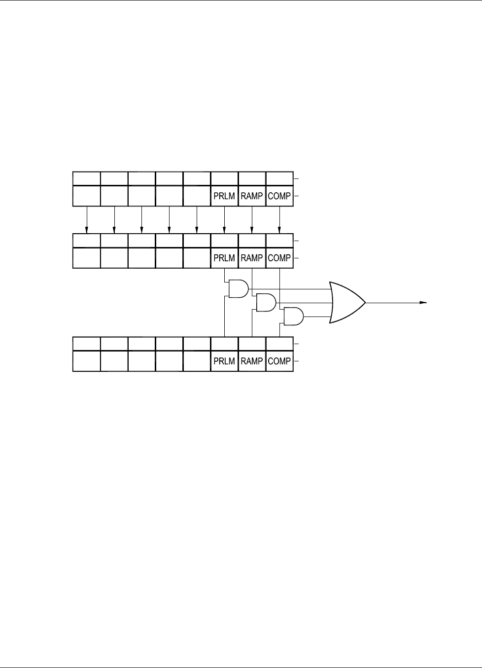
Lake Shore Model 642 Electromagnet Power Supply User’s Manual
Computer Interface Operation 5-9
5.1.4.2.2 Operation Event Register Set
The Operation Event Register reports the following instrument events: ramp done, compliance. Any or all of these events
may be reported in the operation event summary bit through the enable register, see Figure 5-3. The Operation Event
Enable command (OPSTE) programs the enable register and the query command (OPSTE?) reads it. OPSTR? reads the
Operation Event Register. OPST? reads and clears the Operation Condition register. The used bits of the Operation
Event Register are described as follows:
Power Limit, Bit (2) – This bit is set if the output is in power limit.
Ramp Done, Bit (1) – This bit is set when the output current ramp is completed.
Compliance, Bit (0) – This bit is set if the output is in compliance limit.
To Bit 7 (OSB) of
Status Byte Register
(See Figure 5-1.)
OR
AND
Used
Not
NotNotNotNot
OPSTE, Used
OPSTE? UsedUsed Used
Event Enable
Operation
Register 75
64
Name
AND
2
30
1
AND
Bit
Used
Not
Not
Used
Not
Used
Register
OPSTR?
Operation
Event 7
NotNot Not
UsedUsed Used
5
64
Not
Used
7
Condition
OPST?
Register
Operation 4
65
Used
Not
Used
Not Used
Not
3210
Name
Bit
0
12
3Bit
Name
Figure 5-3. Operation Event Register
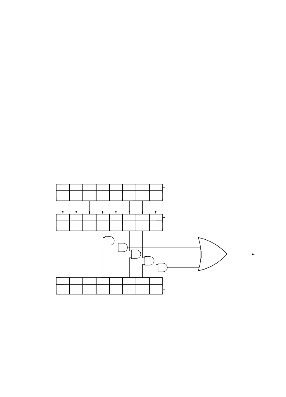
Lake Shore Model 642 Electromagnet Power Supply User’s Manual
5-10 Computer Interface Operation
5.1.4.3 Error Status Register Sets
As shown in Figure 5-1, there are two register sets in the error status system of the Model 642; Hardware Error Status
Register, and Operational Error Status Register.
5.1.4.3.1 Hardware Error Status Register Set
The Hardware Error Status Register reports the following instrument hardware error events: temperature fault, output
over voltage, output over current, DAC processor not responding and output control failure. Any or all of these events
may be reported in the standard event summary bit through the enable register, see Figure 5-4. The Hardware Error
Status Register is the first value of the two values associated with the Error Status Registers. The Error Status Enable
command (ERSTE) programs the enable register and the query command (ERSTE?) reads it. ERSTR? reads and clears
the Error Status Register. The used bits of the Error Status Event Register are described as follows:
Temperature Fault (TF), Bit (4) – This bit is set if the internal temperature of the instrument exceeded the maximum
safe value of 45 °C. The instrument will shut down within 10 seconds of detecting this fault.
Output Over Voltage (OOV), Bit (3) – This bit is set if the output voltage exceeded the compliance voltage limit
setting.
Output Over Current (OOC), Bit (2) – This bit is set if the output current is above 62 A exceeding the maximum
output current of the instrument.
DAC Processor Not Responding (DAC), Bit (1) – This bit is set to indicate that communication to the DAC processor
has failed.
Output Control Failure (OCF), Bit (0) – This bit is set if there is a failure on the output control board.
To Bit 2 (HESB) of
(See Figure 5-1.)
Status Byte Register
NotNot
Event Register Not
Used
5
Used
Not
UsedUsed
ERSTE, ERSTE?
Error Status
Enable Register Not
76
Not
ERSTR? Used Used
NameTF
AND
AND
42301Bit
AND
AND
AND
TF Name
OR
5
5
Used
Not
67
Condition Register
Error Status
ERST?
7 6
Not
Used Used
Not
Error Status Bit103 24
OOV
432
DACTF OCF
10Bit
OOC Name
OOV DAC OCFOOC
OOV DAC OCFOOC
Figure 5-4. Hardware Error Status Register
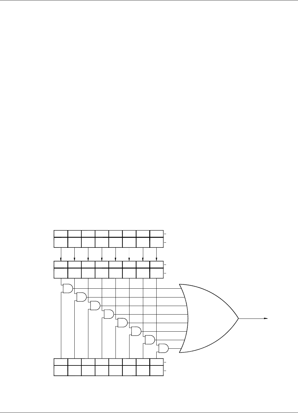
Lake Shore Model 642 Electromagnet Power Supply User’s Manual
Computer Interface Operation 5-11
5.1.4.3.2 Operational Error Status Register Set
The Operational Error Status Register reports the following instrument operational error events: remote enable fault
detected, power supply flow switch fault detected, magnet flow switch fault detected, high line voltage, low line voltage,
temperature high, external current program error, calibration error. Any or all of these events may be reported in the
standard event summary bit through the enable register, see Figure 5-5. The Operational Error Status Register is the
second value of the two values associated with the Error Status Registers. The Error Status Enable command (ERSTE)
programs the enable register and the query command (ERSTE?) reads it. ERSTR? reads and clears the Error Status
Register. The used bits of the Error Status Event Register are described as follows:
Remote Enable Fault Detected (REF), Bit (7) – This bit is set if a fault condition is detected on the remote enable
interlock.
Power Supply Flow Switch Fault Detected (PFF), Bit (6) – This bit is set if a fault condition is detected on the power
supply flow switch interlock.
Magnet Flow Switch Fault Detected (MFF), Bit (5) – This bit is set if a fault condition is detected on the magnet flow
switch interlock.
High Line Voltage (HLV), Bit (4) – This bit is set if the power line voltage exceeds an acceptable amplitude. Operation
can continue but additional heat may be dissipated by the instrument.
Low Line Voltage (LLV), Bit (3) – This bit is set if the power line voltage drops below an acceptable amplitude.
Operation can continue but output voltage may not reach maximum specification.
Temperature High (OOV), Bit (2) – This bit is set if the internal temperature of the instrument exceeded 40 °C. The
output current will be set to zero and will not be settable until the fault is cleared.
External Current Program Error (EPE), Bit (1) – This bit is set if the instrument cannot go into external or sum
current programming modes because the programming voltage is too high. The output current will be set to zero and
will not be settable until the fault is cleared.
Calibration Error (CAL), Bit (0) – This bit is set if the instrument is not calibrated or the calibration data has been
corrupted.
REF PFF NameCALTH EPEMFF HLV LLV
MFF
MFF
5
5
Error Status
Enable Register
ERSTE, ERSTE?
67
REF PFF
REF PFF
ERSTR?
AND
AND
Error Status
ERST?
Event Register 76
OR
AND
AND
EPE
2
3
4
LLVHLV TH
Bit
0
1
CAL Name
AND
AND
AND
CALTH EPELLVHLV Name
AND
42
310Bit
5
Condition Register
Error Status 76 42
30
1Bit
Status Byte Register
(See Figure 5-1.)
To Bit 1 (OESB) of
Figure 5-5. Operational Error Status Register
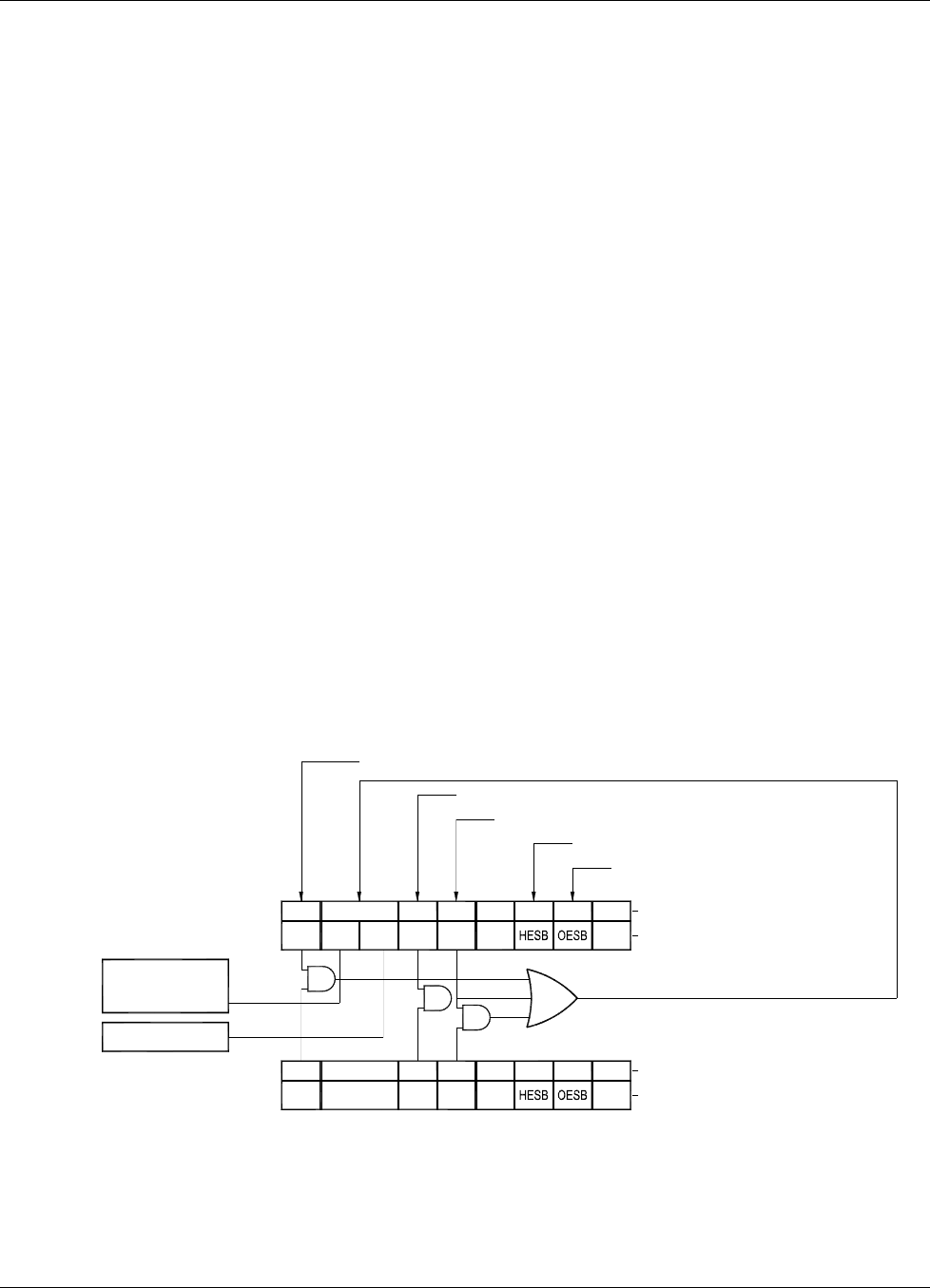
Lake Shore Model 642 Electromagnet Power Supply User’s Manual
5-12 Computer Interface Operation
5.1.4.4 Status Byte and Service Request (SRQ)
As shown in Figure 5-1, the Status Byte Register receives the summary bits from the two status register sets and the
message available summary bit from the output buffer. The status byte is used to generate a service request (SRQ). The
selection of summary bits that will generate an SRQ is controlled by the Service Request Enable Register.
5.1.4.4.1 Status Byte Register
The summary messages from the event registers and output buffer set or clear the summary bits of the Status Byte
Register, see Figure 5-5. These summary bits are not latched. Clearing an event register will clear the corresponding
summary bit in the Status Byte Register. Reading all messages in the output buffer, including any pending queries, will
clear the message available bit. The bits of the Status Byte Register are described as follows:
Operation Summary (OSB), Bit (7) – Set summary bit indicates that an enabled operation event has occurred.
Request Service (RQS)/Master Summary Status (MSS), Bit (6) – This bit is set when a summary bit and the summary
bits corresponding enable bit in the Service Request Enable Register are set. Once set, the user may read and clear the
bit in two different ways, which is why it is referred to as both the RQS and the MSS bit. When this bit goes from low
to high, the Service Request hardware line on the bus is set, this is the RQS function of the bit. See Paragraph
5.1.4.4.3. In addition, the status of the bit may be read with the *STB? query which returns the binary weighted sum of
all bits in the Status Byte, this is the MSS function of the bit.
Performing a serial poll will automatically clear the RQS function but not the MSS function. A *STB? will read the
status of the MSS bit (along with all of the summary bits), but also will not clear it. To clear the MSS bit, either clear
the event register that set the summary bit or disable the summary bit in the Service Request Enable Register.
Event Summary (ESB), Bit (5) – Set summary bit indicates that an enabled standard event has occurred.
Message Available (MAV), Bit (4) – Set summary bit indicates that a message is available in the output buffer.
Bit (3) – Not used.
Hardware Errors Summary (HESB), Bit (2) – Set summary bit indicates that an enabled hardware error event has
occurred.
Operational Errors Summary (OESB), Bit (1) – Set summary bit indicates that an enabled operational error event has
occurred.
AND
AND OR
MSS
*SRE, *SRE?
Read by *STB?
Enable Register
Service Request
OSB
7
Not
Used
6
ESB
53
Not
Used
MAV
42
Name
0
Not
Used
1Bit
RQS AND
7
Status Byte
request. Reset by
Generate service
serial poll.
*STB?
Register OSB
2
3
5
64
MSS
RQS ESB Used
Not
MAV
Bit
0
1
Name
Used
Not
From Operation Condition Register
From Standard Event Status Register
From Output Buffer
From Error Status Register (Hardware)
From Error Status Register (Operational)
Figure 5-6. Status Byte Register and Service Request Enable Register

Lake Shore Model 642 Electromagnet Power Supply User’s Manual
Computer Interface Operation 5-13
5.1.4.4.2 Service Request Enable Register
The Service Request Enable Register is programmed by the user and determines which summary bits of the Status Byte
may set bit 6 (RQS/MSS) to generate a Service Request. Enable bits are logically ANDed with the corresponding
summary bits, see Figure 5-6. Whenever a summary bit is set by an event register and its corresponding enable bit is set
by the user, bit 6 will set to generate a service request. The Service Request Enable command (*SRE) programs the
Service Request Enable Register and the query command (*SRE?) reads it. Reading the Service Request Enable Register
will not clear it. The register may be cleared by the user by sending *SRE 0.
5.1.4.4.3 Using Service Request (SRQ) and Serial Poll
When a Status Byte summary bit (or MAV bit) is enabled by the Service Request Enable Register and goes from 0 to 1,
bit 6 (RQS/MSS) of the status byte will be set. This will send a service request (SRQ) interrupt message to the bus
controller. The user program may then direct the bus controller to serial Poll the instruments on the bus to identify which
one requested service (the one with bit 6 set in its status byte).
Serial polling will automatically clear RQS of the Status Byte Register. This allows subsequent serial polls to monitor bit
6 for an SRQ occurrence generated by other event types. After a serial poll, the same event or any event that uses the
same Status Byte summary bit, will not cause another SRQ unless the event register that caused the first SRQ has been
cleared, typically by a query of the event register.
The serial poll does not clear MSS. The MSS bit stays set until all enabled Status Byte summary bits are cleared,
typically by a query of the associated event register, refer to Paragraph 5.1.4.4.4.
The programming example in Table 5-3 initiates an SRQ when a command error is detected by the instrument.
Table 5-3. Programming Example to Generate an SRQ
Command or Operation Description
*ESR? Read and clear the Standard Event Status Register.
*ESE 32 Enable the Command Error (CME) bit in the Standard Event Status Register
*SRE 32 Enable the Event Summary Bit (ESB) to set the RQS
*ABC Send improper command to instrument to generate a command error
Monitor bus Monitor the bus until the Service Request interrupt (SRQ) is sent.
Initiate Serial Poll Serial Poll the bus to determine which instrument sent the interrupt and clear the RQS bit
in the Status Byte.
*ESR? Read and clear the Standard Event Status Register allowing an SRQ to be generated on
another command error.
5.1.4.4.4 Using Status Byte Query (*STB?)
The Status Byte Query (*STB?) command is similar to a Serial Poll except it is processed like any other instrument
command. The *STB? command returns the same result as a Serial Poll except that the Status Byte bit 6 (RQS/MSS) is
not cleared. In this case bit 6 is considered the MSS bit. Using the *STB? command does not clear any bits in the Status
Byte Register.
5.1.4.4.5 Using Message Available (MAV) Bit
Status Byte summary bit 4 (MAV) indicates that data is available to read into your bus controller. This message may be
used to synchronize information exchange with the bus controller. The bus controller can, for example, send a query
command to the Model 642 and then wait for MAV to set. If the MAV bit has been enabled to initiate an SRQ, the user’s
program can direct the bus controller to look for the SRQ leaving the bus available for other use. The MAV bit will be
clear whenever the output buffer is empty.

Lake Shore Model 642 Electromagnet Power Supply User’s Manual
5-14 Computer Interface Operation
5.1.4.4.6 Using Operation Complete (*OPC) and Operation Complete Query (*OPC?)
The Operation Complete (*OPC) and Operation Complete Query (*OPC?) are both used to indicate when pending
device operations complete. However, the commands operate with two distinct methods.
The *OPC command is used in conjunction with bit 0 (OPC) of the Standard Event Status Register. If *OPC is sent as
the last command in a command sequence, bit 0 will be set when the instrument completes the operation that was
initiated by the command sequence. Additional commands may be sent between the instrument and the bus controller
while waiting for the initial pending operation to complete. A typical use of this function would be to enable the OPC bit
to generate an SRQ and include the *OPC command when programming the instrument. The bus controller could then
be instructed to look for an SRQ allowing additional communication with the instrument while the initial process
executes.
The *OPC? query has no interaction with bit 0 (OPC) of the Standard Event Status Register. If the *OPC? query is sent
at the end of a command sequence, the bus will be held until the instrument completes the operation that was initiated by
the command sequence. Additional commands (except *RST) should not be sent until the operation is complete as erratic
operation will occur. Once the sequence is complete a 1 will be placed in the output buffer. This function is typically
used to signal a completed operation without monitoring the SRQ. It is also used when it is important to prevent any
additional communication on the bus during a pending operation.
5.1.5 IEEE-488 Interface Example Programs
A Visual Basic program is included to illustrate the IEEE-488 communication functions of the instrument. Instructions
for setting up the IEEE-488 Board is included in Section 5.1.5.1. Refer to Section 5.1.5.2 for instructions on how to setup
the program. The Visual Basic code is provided in Table 5-5. A description of program operation is provided in
Section 5.1.5.3. While the hardware and software required to produce and implement these programs not included with
the instrument, the concepts illustrated apply to most applications.
5.1.5.1 IEEE-488 Interface Board Installation for Visual Basic Program
This procedure works for Plug and Play GPIB Hardware and Software for Windows 98/95. This example uses the
AT-GPIB/TNT GPIB card.
1. Install the GPIB Plug and Play Software and Hardware using National Instruments instructions.
2. Verify that the following files have been installed to the Windows System folder:
a. gpib-32.dll
b. gpib.dll
c. gpib32ft.dll
Files b and c support any 16-bit Windows GPIB applications being used.
3. Locate the following files and make note of their location. These files will be used during the development process
of a Visual Basic program.
a. Niglobal.bas
b. Vbib-32.bas
NOTE: If the files in Steps 2 and 3 are not installed on your computer, they may be copied from your National
Instruments setup disks or they may be downloaded from www.ni.com.
4. Configure the GPIB by selecting the System icon in the Windows Control Panel located under Settings on the Start
Menu. Configure the GPIB Settings as shown in Figure 5-7. Configure the DEV12 Device Template as shown in
Figure 5-8. Be sure to check the Readdress box.
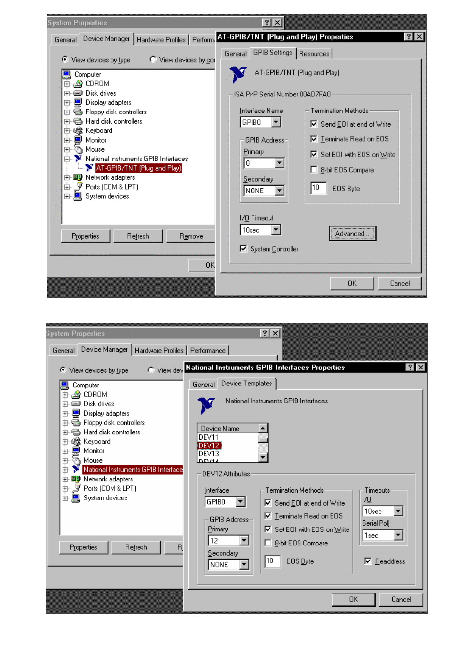
Lake Shore Model 642 Electromagnet Power Supply User’s Manual
Computer Interface Operation 5-15
Figure 5-7. GPIB0 Setting Configuration
Figure 5-8. DEV 12 Device Template Configuration
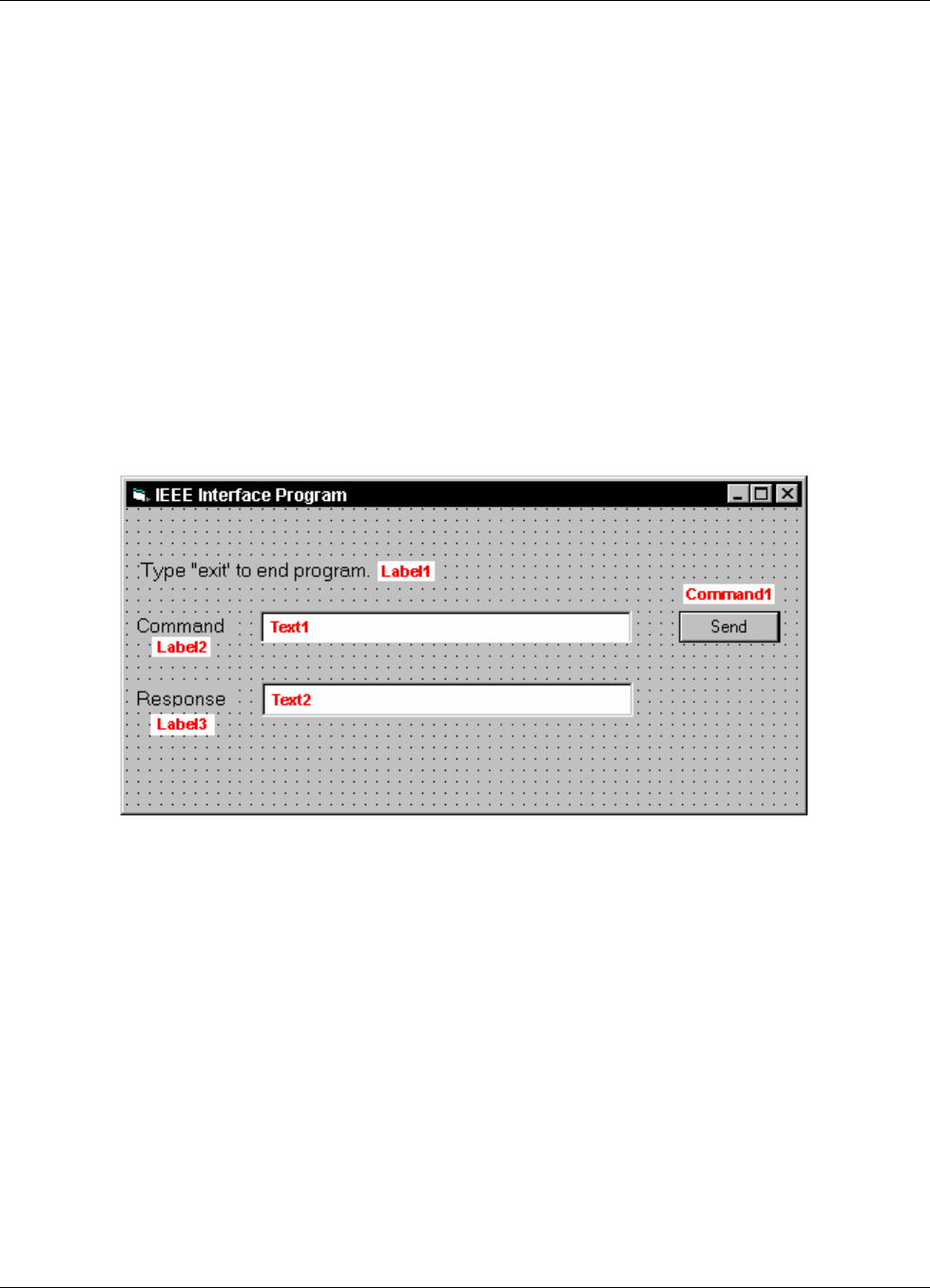
Lake Shore Model 642 Electromagnet Power Supply User’s Manual
5-16 Computer Interface Operation
5.1.5.2 Visual Basic IEEE-488 Interface Program Setup
This IEEE-488 interface program works with Visual Basic 6.0 (VB6) on an IBM PC (or compatible) with a Pentium-
class processor. A Pentium 90 or higher is recommended, running Windows 95 or better. It assumes your IEEE-488
(GPIB) card is installed and operating correctly (refer to Paragraph 5.1.5.1). Use the following procedure to develop the
IEEE-488 Interface Program in Visual Basic.
1. Start VB6.
2. Choose Standard EXE and select Open.
3. Resize form window to desired size.
4. On the Project Menu, select Add Module, select the Existing tab, then navigate to the location on your computer to
add the following files: Niglobal.bas and Vbib-32.bas.
5. Add controls to form:
a. Add three Label controls to the form.
b. Add two TextBox controls to the form.
c. Add one CommandButton control to the form.
6. On the View Menu, select Properties Window.
7. In the Properties window, use the dropdown list to select between the different controls of the current project.
10. Set the properties of the controls as defined in Table 5-4.
11. Save the program.
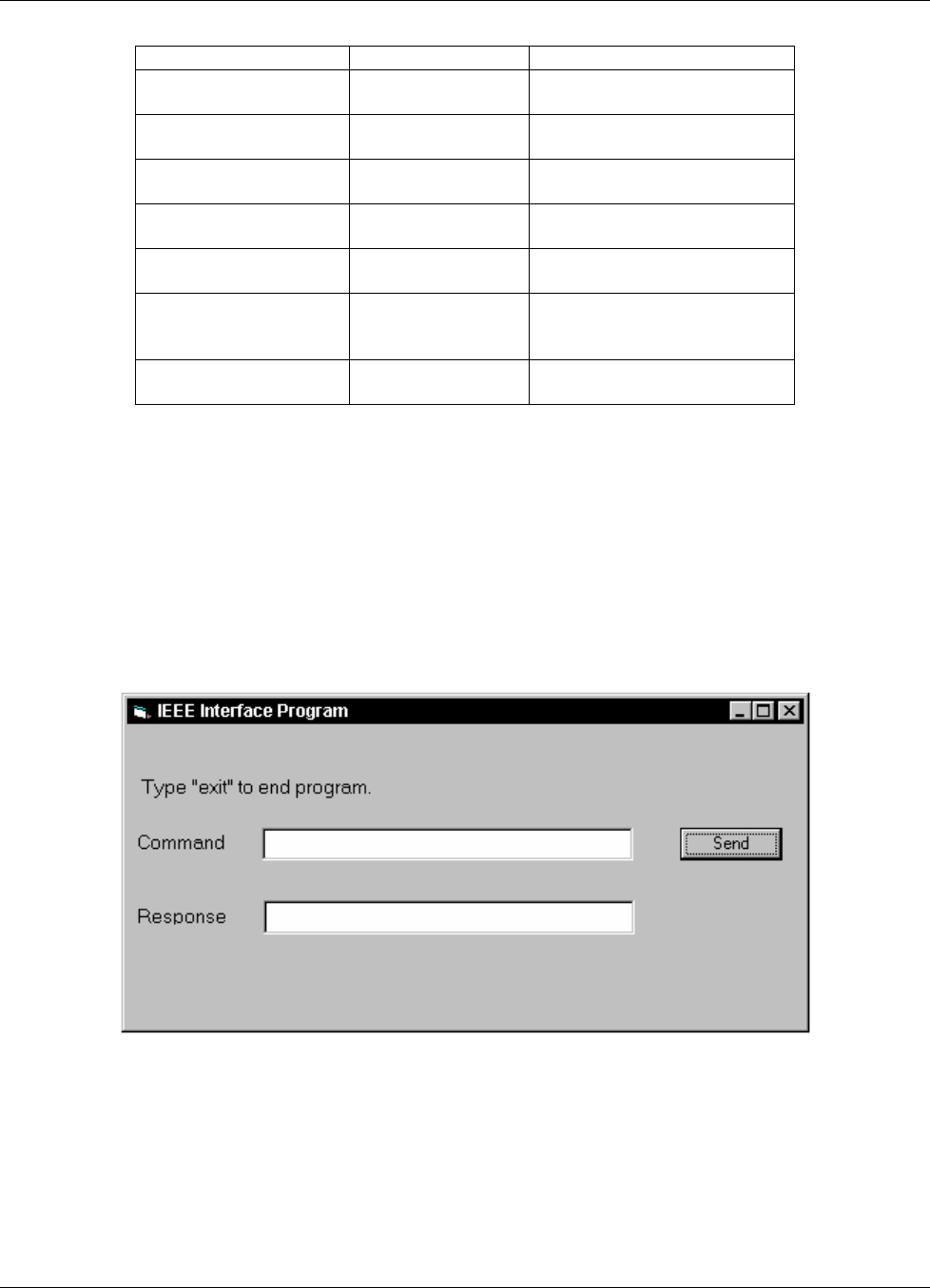
Lake Shore Model 642 Electromagnet Power Supply User’s Manual
Computer Interface Operation 5-17
Table 5-4. IEEE-488 Interface Program Control Properties
Current Name Property New Value
Label1 Name
Caption
lblExitProgram
Type “exit” to end program.
Label2 Name
Caption
lblCommand
Command
Label3 Name
Caption
lblResponse
Response
Text1 Name
Text
txtCommand
<blank>
Text2 Name
Text
txtResponse
<blank>
Command1 Name
Caption
Default
cmdSend
Send
True
Form1 Name
Caption
From IEEE-488
IEEE-488 Interface Program
12. Add code (provided in Table 5-5).
a. In the Code Editor window, under the Object dropdown list, select (General). Add the statement: Public gSend
as Boolean
b. Double Click on cmdSend. Add code segment under Private Sub cmdSend_Click( ) as shown in Table 5-5.
c. In the Code Editor window, under the Object dropdown list, select Form. Make sure the Procedure dropdown
list is set at Load. The Code window should have written the segment of code: Private Sub Form_Load( ). Add
the code to this subroutine as shown in Table 5-5.
13. Save the program.
14. Run the program. The program should resemble the following.
15. Type in a command or query in the Command box as described in Paragraph 5.1.5.5.
16. Press Enter or select the Send button with the mouse to send command.
17. Type Exit and press Enter to quit.

Lake Shore Model 642 Electromagnet Power Supply User’s Manual
5-18 Computer Interface Operation
Table 5-5. Visual Basic IEEE-488 Interface Program
Public gSend As Boolean 'Global used for Send button state
Private Sub cmdSend_Click() 'Routine to handle Send button press
gSend = True 'Set Flag to True
End Sub
Private Sub Form_Load() 'Main code section
Dim strReturn As String 'Used to return response
Dim term As String 'Terminators
Dim strCommand As String 'Data string sent to instrument
Dim intDevice As Integer 'Device number used with IEEE
frmIEEE.Show 'Show main window
term = Chr(13) & Chr(10) 'Terminators are <CR><LF>
strReturn = "" 'Clear return string
Call ibdev(0, 12, 0, T10s, 1, &H140A, intDevice) 'Initialize the IEEE device
Call ibconfig(intDevice, ibcREADDR,1) 'Setup Repeat Addressing
Do
Do 'Wait loop
DoEvents 'Give up processor to other events
Loop Until gSend = True 'Loop until Send button pressed
gSend = False 'Set Flag as False
strCommand = frmIEEE.txtCommand.Text 'Get Command
strReturn = "" 'Clear response display
strCommand = UCase(strCommand) 'Set all characters to upper case
If strCommand = "EXIT" Then 'Get out on EXIT
End
End If
Call ibwrt(intDevice, strCommand & term) 'Send command to instrument
If (ibsta And EERR) Then 'Check for IEEE errors
'do error handling if needed 'Handle errors here
End If
If InStr(strCommand, "?") <> 0 Then 'Check to see if query
strReturn = Space(100) 'Build empty return buffer
Call ibrd(intDevice, strReturn) 'Read back response
If (ibsta And EERR) Then 'Check for IEEE errors
'do error handling if needed 'Handle errors here
End If
If strReturn <> "" Then 'Check if empty string
strReturn = RTrim(strReturn) 'Remove extra spaces and Terminators
Do While Right(strReturn, 1) = Chr(10) Or Right(strReturn, 1) = Chr(13)
strReturn = Left(strReturn, Len(strReturn) - 1)
Loop
Else
strReturn = "No Response" 'Send No Response
End If
frmIEEE.txtResponse.Text = strReturn 'Put response in text on main form
End If
Loop
End Sub
Lake Shore Model 642 Electromagnet Power Supply User’s Manual
Computer Interface Operation 5-19
Primary GPIB Address ........ Primary GPIB Address ........ àà00
Secondary GPIB Address ...... NONESecondary GPIB Address ...... NONE
Timeout setting ............. 10secTimeout setting ............. 10sec
Terminate Read on EOS ....... YesTerminate Read on EOS ....... Yes
Set EOI with EOS on Writes .. YesSet EOI with EOS on Writes .. Yes
Type of compare on EOS ...... 7-BitType of compare on EOS ...... 7-Bit
EOS byte .................... 0AhEOS byte .................... 0Ah
Send EOI at end of Write .... YesSend EOI at end of Write .... Yes
System Controller ........... YesSystem Controller ........... Yes
Assert REN when SC .......... NoAssert REN when SC .......... No
Enable Auto Serial Polling .. NoEnable Auto Serial Polling .. No
Enable CIC Protocol ......... NoEnable CIC Protocol ......... No
Bus Timing .................. 500nsecBus Timing .................. 500nsec
Parallel Poll Duration ...... DefaultParallel Poll Duration ...... Default
Use this GPIB board ......... YesUse this GPIB board ......... Yes
Board Type .................. PCIIBoard Type .................. PCII
Base I/O Address ............ 02B8hBase I/O Address ............ 02B8h
National InstrumentsNational Instruments GPIB0 Configuration GPIB-PC2/2A Ver 2.1
éé Select the primary GPIB address by
using the left and right arrow keys.
This address is used to compute the
talk and listen addresses which
identify the board or device on the
GPIB. Valid primary addresses range
from 0 to 30 (00H to 1EH).
* Adding 32 to the primary address
forms the Listen Address (LA).
* Adding 64 to the primary address
forms the Talk Address (TA).
EXAMPLE: Selecting a primary address
of 10 yields the following:
10 + 32 = 42 (Listen address)
10 + 64 = 74 (Talk address)
F1: Help F6: Reset Value F9/Esc: Return to Map Ctl PgUp/PgDn: Next/Prev Board
Primary GPIB Address ........ àà12
Secondary GPIB Address ...... NONE
Timeout setting ............. 10sec
Serial Poll Timeout ......... 1sec
Terminate Read on EOS ....... Yes
Set EOI with EOS on Writes .. Yes
Type of compare on EOS ...... 7-Bit
EOS byte .................... 0Ah
Send EOI at end of Write .... Yes
Enable Repeat Addressing .... Yes
National Instruments DEV12 Configuration GPIB-PC2/2A Ver 2.1
Select the primary GPIB address by
using the left and right arrow keys.
This address is used to compute the
talk and listen addresses which
identify the board or device on the
GPIB. Valid primary addresses range
from 0 to 30 (00H to 1EH).
* Adding 32 to the primary address
forms the Listen Address (LA).
* Adding 64 to the primary address
forms the Talk Address (TA).
EXAMPLE: Selecting a primary address
of 10 yields the following:
10 + 32 = 42 (Listen address)
10 + 64 = 74 (Talk address)
F1: Help F6: Reset Value F9/Esc: Return to Map Ctl PgUp/PgDn: Next/Prev Board
êê
êê
éé
IBCONF.EXE.eps
Figure 5-9. Typical National Instruments GPIB Configuration from IBCONF.EXE

Lake Shore Model 642 Electromagnet Power Supply User’s Manual
5-20 Computer Interface Operation
5.1.5.3 Program Operation
Once the running, try the following commands and observe the response of the instrument. Input from the user is shown
in bold and terminators are added by the program. The word [term] indicates the required terminators included with the
response.
ENTER COMMAND? *IDN? Identification query. Instrument will return a string identifying itself.
RESPONSE: LSCI,MODELModel 642,1234567,06122006[term]
ENTER COMMAND? SETI? Output current setting query. Instrument will return a string with the
present output current setting.
RESPONSE: +20.0545[term]
ENTER COMMAND? XPGM 0 External program mode command. Instrument will set program mode
to internal. No response will be sent.
ENTER COMMAND? XPGM? External program mode query. Instrument will return a string with the
present external program mode setting.
RESPONSE: 0[term]
ENTER COMMAND? XPGM 1;XPGM? External program mode command followed by a query. Instrument will
change to external programming mode, then return a string
RESPONSE: 1[term] with the present setting.
The following are additional notes on using either IEEE-488 Interface program.
• If you enter a correctly spelled query without a “?,” nothing will be returned. Incorrectly spelled commands and
queries are ignored. Commands and queries should have a space separating the command and associated parameters.
• Leading zeros and zeros following a decimal point are not needed in a command string, but are sent in response to a
query. A leading “+” is not required but a leading “–” is required.
5.1.6 Troubleshooting
New Installation
1. Check instrument address.
2. Always send terminators.
3. Send entire message string at one time including terminators.
4. Send only one simple command at a time until communication is established.
5. Be sure to spell commands correctly and use proper syntax.
6. Attempt both ‘Talk’ and ‘Listen’ functions. If one works but not the other, the hardware connection is working, so
look at syntax, terminators, and command format.
7. If only one message is received after resetting the interface, check the “repeat addressing” setting. It should be
enabled.
Old Installation No Longer Working
8. Power instrument off then on again to see if it is a soft failure.
9. Power computer off then on again to see if the IEEE-488 card is locked up.
10. Verify that the address has not been changed on the instrument during a memory reset.
11. Check all cable connections.
Intermittent Lockups
12. Check cable connections and length.
13. Increase delay between all commands to 50 ms to make sure instrument is not being over loaded.

Lake Shore Model 642 Electromagnet Power Supply User’s Manual
Computer Interface Operation 5-21
5.2 SERIAL INTERFACE OVERVIEW
The serial interface used in the Model 642 is commonly referred to as an RS-232C interface. RS-232C is a standard of
the Electronics Industries Association (EIA) that describes one of the most common interfaces between computers and
electronic equipment. The RS-232C standard is quite flexible and allows many different configurations. However, any
two devices claiming RS-232C compatibility cannot necessarily be plugged together without interface setup. The
remainder of this paragraph briefly describes the key features of a serial interface that are supported by the instrument.
A customer supplied computer with similarly configured interface port is required to enable communication.
5.2.1 Changing Baud Rate
To select the Serial Interface Baud Rate press the Computer Interface key. The first computer interface screen appears
as a prompt for Baud.
Computer Interface
Select With °®
Baud: 9600
Use the S or T key to select 9600, 19200, 38400, or 57600 Baud. The default is 9600 Baud. Press Enter to accept the
new selection and continue to the next setting screen. Press Escape to cancel the new selection and return to the normal
display.
5.2.2 Physical Connection
The Model 642 has a 9 pin D-Subminiature plug on the rear panel for serial communication. The original RS-232C
standard specifies 25 pins but both 9- and 25-pin connectors are commonly used in the computer industry. Many third
party cables exist for connecting the instrument to computers with either 9- or 25-pin connectors. Paragraph 7.10.5 gives
the most common pin assignments for 9- and 25-pin connectors. Please note that not all pins or functions are supported
by the Model 642.
The instrument serial connector is the plug half of a mating pair and must be matched with a socket on the cable. If a
cable has the correct wiring configuration but also has a plug end, a “gender changer” can be used to mate two plug ends
together.
The letters DTE near the interface connector stand for Data Terminal Equipment and indicate the pin connection of the
directional pins such as transmit data (TD) and receive data (RD). Equipment with Data Communications Equipment
(DCE) wiring can be connected to the instrument with a straight through cable. As an example, Pin 3 of the DTE
connector holds the transmit line and Pin 3 of the DCE connector holds the receive line so the functions complement.
It is likely both pieces of equipment are wired in the DTE configuration. In this case Pin 3 on one DTE connector (used
for transmit) must be wired to Pin 2 on the other (used for receive). Cables that swap the complementing lines are called
null modem cables and must be used between two DTE wired devices. Null modem adapters are also available for use
with straight through cables. Paragraph 7.10.5 illustrates suggested cables that can be used between the instrument and
common computers.
The instrument uses drivers to generate the transmission voltage levels required by the RS-232C standard. These
voltages are considered safe under normal operating conditions because of their relatively low voltage and current limits.
The drivers are designed to work with cables up to 50 feet in length.

Lake Shore Model 642 Electromagnet Power Supply User’s Manual
5-22 Computer Interface Operation
5.2.3 Hardware Support
The Model 642 interface hardware supports the following features. Asynchronous timing is used for the individual bit
data within a character. This timing requires start and stop bits as part of each character so the transmitter and receiver
can be resynchronized between each character. Half duplex transmission allows the instrument to be either a transmitter
or a receiver of data but not at the same time. Communication speeds of 9600, 19200, 38400, or 57600 Baud are
supported. The Baud rate is the only interface parameter that can be changed by the user.
Hardware handshaking is not supported by the instrument. Handshaking is often used to guarantee that data message
strings do not collide and that no data is transmitted before the receiver is ready. In this instrument appropriate software
timing substitutes for hardware handshaking. User programs must take full responsibility for flow control and timing as
described in Paragraph 5.2.6.
5.2.4 Character Format
A character is the smallest piece of information that can be transmitted by the interface. Each character is 10 bits long
and contains data bits, bits for character timing and an error detection bit. The instrument uses 7 bits for data in the
ASCII format. One start bit and one stop bit are necessary to synchronize consecutive characters. Parity is a method of
error detection. One parity bit configured for odd parity is included in each character.
ASCII letter and number characters are used most often as character data. Punctuation characters are used as delimiters
to separate different commands or pieces of data. Two special ASCII characters, carriage return (CR 0DH) and line feed
(LF 0AH), are used to indicate the end of a message string.
Table 5-6. Serial Interface Specifications
Connector Type:
Connector Wiring:
Voltage Levels:
Transmission Distance:
Timing Format:
Transmission Mode:
Baud Rate:
Handshake:
Character Bits:
Parity:
Terminators:
Command Rate:
9-pin D-style connector plug
DTE
EIA RS-232C Specified
50 feet maximum
Asynchronous
Half Duplex
9600, 19200, 38400, 57600
Software timing
1 Start, 7 Data, 1 Parity, 1 Stop
Odd
CR(0DH) LF(0AH)
20 commands per second maximum
5.2.5 Message Strings
A message string is a group of characters assembled to perform an interface function. There are three types of message
strings commands, queries and responses. The computer issues command and query strings through user programs, the
instrument issues responses. Two or more command or query strings can be chained together in one communication but
they must be separated by a semi-colon (;). The total communication string must not exceed 255 characters in length.
A command string is issued by the computer and instructs the instrument to perform a function or change a parameter
setting. The format is:
<command mnemonic><space><parameter data><terminators>.
Command mnemonics and parameter data necessary for each one is described in Paragraph 5.3. Terminators must be
sent with every message string.

Lake Shore Model 642 Electromagnet Power Supply User’s Manual
Computer Interface Operation 5-23
Message Strings (Continued)
A query string is issued by the computer and instructs the instrument to send a response. The query format is:
<query mnemonic><?><space><parameter data><terminators>.
Query mnemonics are often the same as commands with the addition of a question mark. Parameter data is often
unnecessary when sending queries. Query mnemonics and parameter data if necessary is described in Paragraph 5.3.
Terminators must be sent with every message string. The computer should expect a response very soon after a query
is sent.
A response string is the instruments response or answer to a query string. The instrument will respond to the last query
or queries it receives. The response can be a reading value, status report or the present value of a parameter. Response
data formats are listed along with the associated queries in Paragraph 5.3. The response is sent as soon as possible after
the instrument receives the query. Typically it takes 10 ms for the instrument to begin the response. Some responses
take longer.
5.2.6 Message Flow Control
It is important to remember that the user program is in charge of the serial communication at all times. The instrument
cannot initiate communication, determine which device should be transmitting at a given time or guarantee timing
between messages. All of this is the responsibility of the user program.
When issuing commands only the user program should:
• Properly format and transmit the command including terminators as one string.
• Guarantee that no other communication is started for 50 ms after the last character is transmitted.
• Not initiate communication more than 20 times per second.
When issuing queries or queries and commands together the user program should:
• Properly format and transmit the query including terminators as one string.
• Prepare to receive a response immediately.
• Receive the entire response from the instrument including the terminators.
• Guarantee that no other communication is started during the response or for 50 ms after it completes.
• Not initiate communication more than 20 times per second.
Failure to follow these simple rules will result in inability to establish communication with the instrument or intermittent
failures in communication.
5.2.7 Serial Interface Example Programs
A Visual BASIC program is included to illustrate the serial communication functions of the instrument. Refer to
Paragraph 5.2.7.1 for instructions on how to setup the program. The Visual Basic code is provided in Table 5-8. Refer to
Paragraph 5.2.7.2 for instructions on how to setup the program. A description of operation is provided in Paragraph
5.2.7.2. While the hardware and software required to produce and implement these programs not included with the
instrument, the concepts illustrated apply to almost any application where these tools are available.
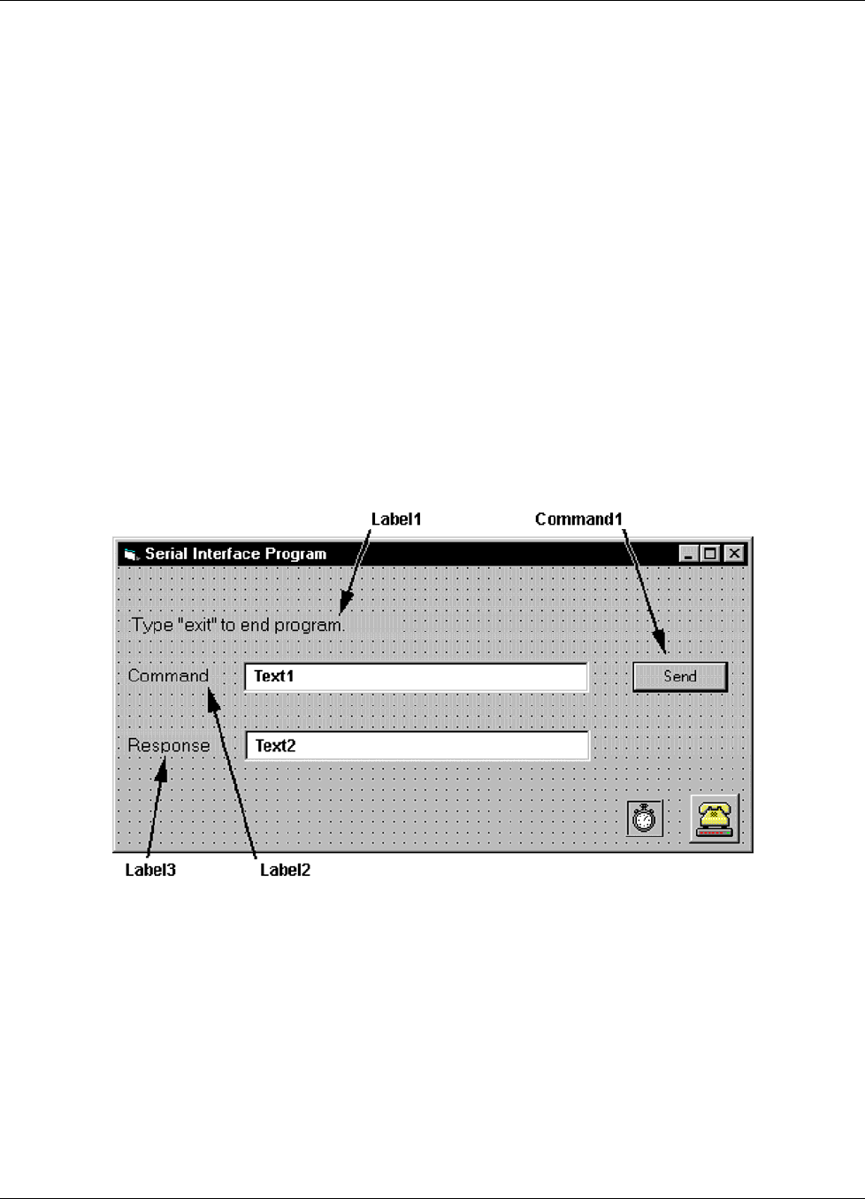
Lake Shore Model 642 Electromagnet Power Supply User’s Manual
5-24 Computer Interface Operation
5.2.7.1 Visual Basic Serial Interface Program Setup
The serial interface program works with Visual Basic 6.0 (VB6) on an IBM PC (or compatible) with a Pentium-class
processor. A Pentium 90 or higher is recommended, running Windows 95 or better, with a serial interface. It uses the
COM1 communications port at 9600 Baud. Use the following procedure to develop the Serial Interface Program in
Visual Basic.
1. Start VB6.
2. Choose Standard EXE and select Open.
3. Resize form window to desired size.
4. On the Project Menu, click Components to bring up a list of additional controls available in VB6.
5. Scroll through the controls and select Microsoft Comm Control 6.0. Select OK. In the toolbar at the left of the
screen, the Comm Control will have appeared as a telephone icon.
6. Select the Comm control and add it to the form.
7. Add controls to form:
a. Add three Label controls to the form.
b. Add two TextBox controls to the form.
c. Add one CommandButton control to the form.
d. Add one Timer control to the form.
8. On the View Menu, select Properties Window.
9. In the Properties window, use the dropdown list to select between the different controls of the current project.
10. Set the properties of the controls as defined in Table 5-7.
11. Save the program.
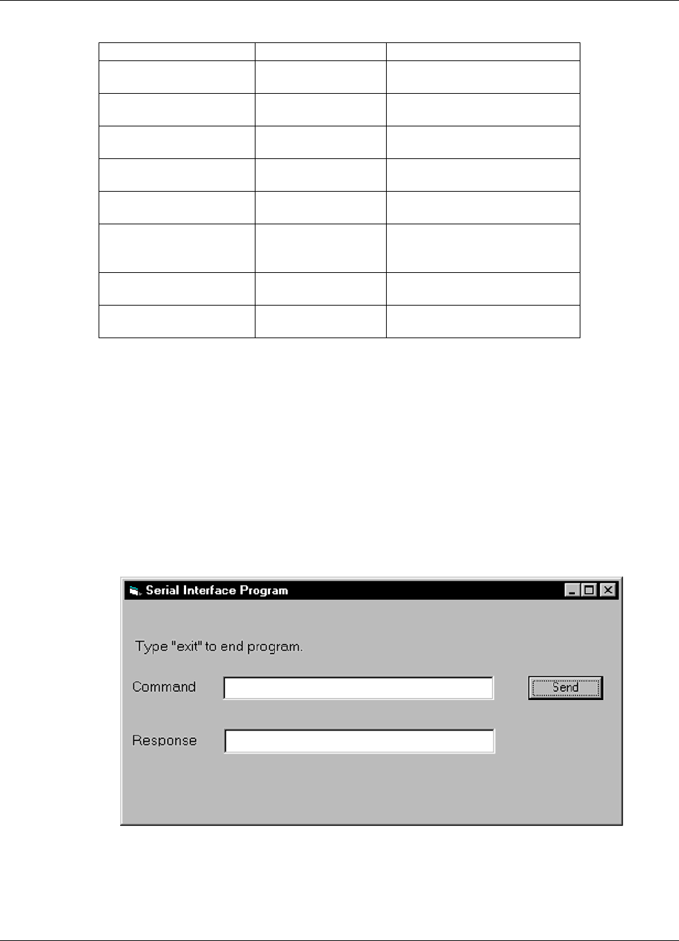
Lake Shore Model 642 Electromagnet Power Supply User’s Manual
Computer Interface Operation 5-25
Table 5-7 Serial Interface Program Control Properties
Current Name Property New Value
Label1 Name
Caption
lblExitProgram
Type “exit” to end program.
Label2 Name
Caption
lblCommand
Command
Label3 Name
Caption
lblResponse
Response
Text1 Name
Text
txtCommand
<blank>
Text2 Name
Text
txtResponse
<blank>
Command1 Name
Caption
Default
cmdSend
Send
True
Form1 Name
Caption
frmSerial
Serial Interface Program
Timer1 Enabled
Interval
False
10
12. Add code (provided in Table 5-8).
a. In the Code Editor window, under the Object dropdown list, select (General). Add the statement: Public gSend
as Boolean
b. Double Click on cmdSend. Add code segment under Private Sub cmdSend_Click( ) as shown in Table 5-8.
c. In the Code Editor window, under the Object dropdown list, select Form. Make sure the Procedure dropdown
list is set at Load. The Code window should have written the segment of code: Private Sub Form_Load( ).
Add the code to this subroutine as shown in Table 5-8.
d. Double Click on the Timer control. Add code segment under Private Sub Timer1_Timer() as shown in
Table 5-8.
e. Make adjustments to code if different Com port settings are being used.
13. Save the program.
14. Run the program. The program should resemble the following.
15. Type in a command or query in the Command box as described in Paragraph 5.2.7.2.
16. Press Enter or select the Send button with the mouse to send command.
17. Type Exit and press Enter to quit.

Lake Shore Model 642 Electromagnet Power Supply User’s Manual
5-26 Computer Interface Operation
Table 5-8. Visual Basic Serial Interface Program
Public gSend As Boolean 'Global used for Send button state
Private Sub cmdSend_Click() 'Routine to handle Send button press
gSend = True 'Set Flag to True
End Sub
Private Sub Form_Load() 'Main code section
Dim strReturn As String 'Used to return response
Dim strHold As String 'Temporary character space
Dim Term As String 'Terminators
Dim ZeroCount As Integer 'Counter used for Timing out
Dim strCommand As String 'Data string sent to instrument
frmSerial.Show 'Show main window
Term = Chr(13) & Chr(10) 'Terminators are <CR><LF>
ZeroCount = 0 'Initialize counter
strReturn = "" 'Clear return string
strHold = "" 'Clear holding string
If frmSerial.MSComm1.PortOpen = True Then 'Close serial port to change settings
frmSerial.MSComm1.PortOpen = False
End If
frmSerial.MSComm1.CommPort = 1 'Example of Comm 1
frmSerial.MSComm1.Settings = "9600,o,7,1" 'Example of 9600 Baud,Parity,Data,Stop
frmSerial.MSComm1.InputLen = 1 'Read one character at a time
frmSerial.MSComm1.PortOpen = True 'Open port
Do
Do 'Wait loop
DoEvents 'Give up processor to other events
Loop Until gSend = True 'Loop until Send button pressed
gSend = False 'Set Flag as false
strCommand = frmSerial.txtCommand.Text 'Get Command
strReturn = "" 'Clear response display
strCommand = UCase(strCommand) 'Set all characters to upper case
If strCommand = "EXIT" Then 'Get out on EXIT
End
End If
frmSerial.MSComm1.Output = strCommand & Term 'Send command to instrument
If InStr(strCommand, "?") <> 0 Then 'Check to see if query
While (ZeroCount < 20) And (strHold <> Chr$(10)) 'Wait for response
If frmSerial.MSComm1.InBufferCount = 0 Then 'Add 1 to timeout if no character
frmSerial.Timer1.Enabled = True
Do
DoEvents 'Wait for 10 millisecond timer
Loop Until frmSerial.Timer1.Enabled = False
ZeroCount = ZeroCount + 1 'Timeout at 2 seconds
Else
ZeroCount = 0 'Reset timeout for each character
strHold = frmSerial.MSComm1.Input 'Read in one character
strReturn = strReturn + strHold 'Add next character to string
End If
Wend 'Get characters until terminators
If strReturn <> "" Then 'Check if string empty
strReturn = Mid(strReturn, 1, InStr(strReturn, Term) – 1) 'Strip terminators
Else
strReturn = "No Response" 'Send No Response
End If
frmSerial.txtResponse.Text = strReturn 'Put response in textbox on main form
strHold = "" 'Reset holding string
ZeroCount = 0 'Reset timeout counter
End If
Loop
End Sub
Private Sub Timer1_Timer() 'Routine to handle Timer interrupt
frmSerial.Timer1.Enabled = False 'Turn off timer
End Sub

Lake Shore Model 642 Electromagnet Power Supply User’s Manual
Computer Interface Operation 5-27
5.2.7.2 Program Operation
Once the example program is running, try the following commands and observe the response of the instrument. Input
from the user is shown in bold and terminators are added by the program. The word [term] indicates the required
terminators included with the response.
ENTER COMMAND? *IDN? Identification query. Instrument will return a string identifying itself.
RESPONSE: LSCI,MODELModel 642,1234567,06122006[term]
ENTER COMMAND? SETI? Output current setting query. Instrument will return a string with the
present output current setting.
RESPONSE: +20.0545[term]
ENTER COMMAND? XPGM 0 External program mode command. Instrument will set program mode
to internal. No response will be sent.
ENTER COMMAND? XPGM? External program mode query. Instrument will return a string with the
present external program mode setting.
RESPONSE: 0[term]
ENTER COMMAND? XPGM 1;XPGM? External program mode command followed by a query. Instrument will
change to external programming mode, then return a string
RESPONSE: 1[term] with the present setting.
The following are additional notes on using either IEEE-488 Interface program.
• If you enter a correctly spelled query without a “?,” nothing will be returned. Incorrectly spelled commands and
queries are ignored. Commands and queries should have a space separating the command and associated parameters.
• Leading zeros and zeros following a decimal point are not needed in a command string, but are sent in response to a
query. A leading “+” is not required but a leading “–” is required.
5.2.8 Troubleshooting
New Installation
1. Check instrument Baud rate.
2. Make sure transmit (TD) signal line from the instrument is routed to receive (RD) on the computer and vice versa.
(Use a null modem adapter if not).
3. Always send terminators.
4. Send entire message string at one time including terminators. (Many terminal emulation programs do not.)
5. Send only one simple command at a time until communication is established.
6. Be sure to spell commands correctly and use proper syntax.
Old Installation No Longer Working
7. Power instrument off then on again to see if it is a soft failure.
8. Power computer off then on again to see if communication port is locked up.
9. Verify that Baud rate has not been changed on the instrument during a memory reset.
10. Check all cable connections.
Intermittent Lockups
11. Check cable connections and length.
12. Increase delay between all commands to 100 ms to make sure instrument is not being over loaded.

Lake Shore Model 642 Electromagnet Power Supply User’s Manual
5-28 Computer Interface Operation
5.3 COMMAND SUMMARY
This paragraph provides a listing of the IEEE-488 and Serial Interface Commands. A summary of all the commands is
provided in Table 5-9. All the commands are detailed in Paragraph 5.3.1, which is presented in alphabetical order.
Sample Command Format
SETI Output Current Setting Command
Input: SETI <current> [term]
Format: ±nn.nnnn
<current> Specifies the output current setting: 0.0000 – ±70.1000A.
Remarks: Sets the current value that the output will ramp to at the present ramp rate.
Setting value is limited by LIMIT.
Sample Query Format
SETI? Output Current Setting Query
Input: SETI? [term]
Returned: <current> [term]
Format: ±nn.nnnn (Refer to command for description)
Key
Q Begins common interface command.
? Required to identify queries.
aa… String of alpha numeric characters.
±nn… String of number characters that may include a decimal point.
[term] Terminator characters.
<…> Indicated a parameter field, many are command specific.
<state> Parameter field with only On/Off states.
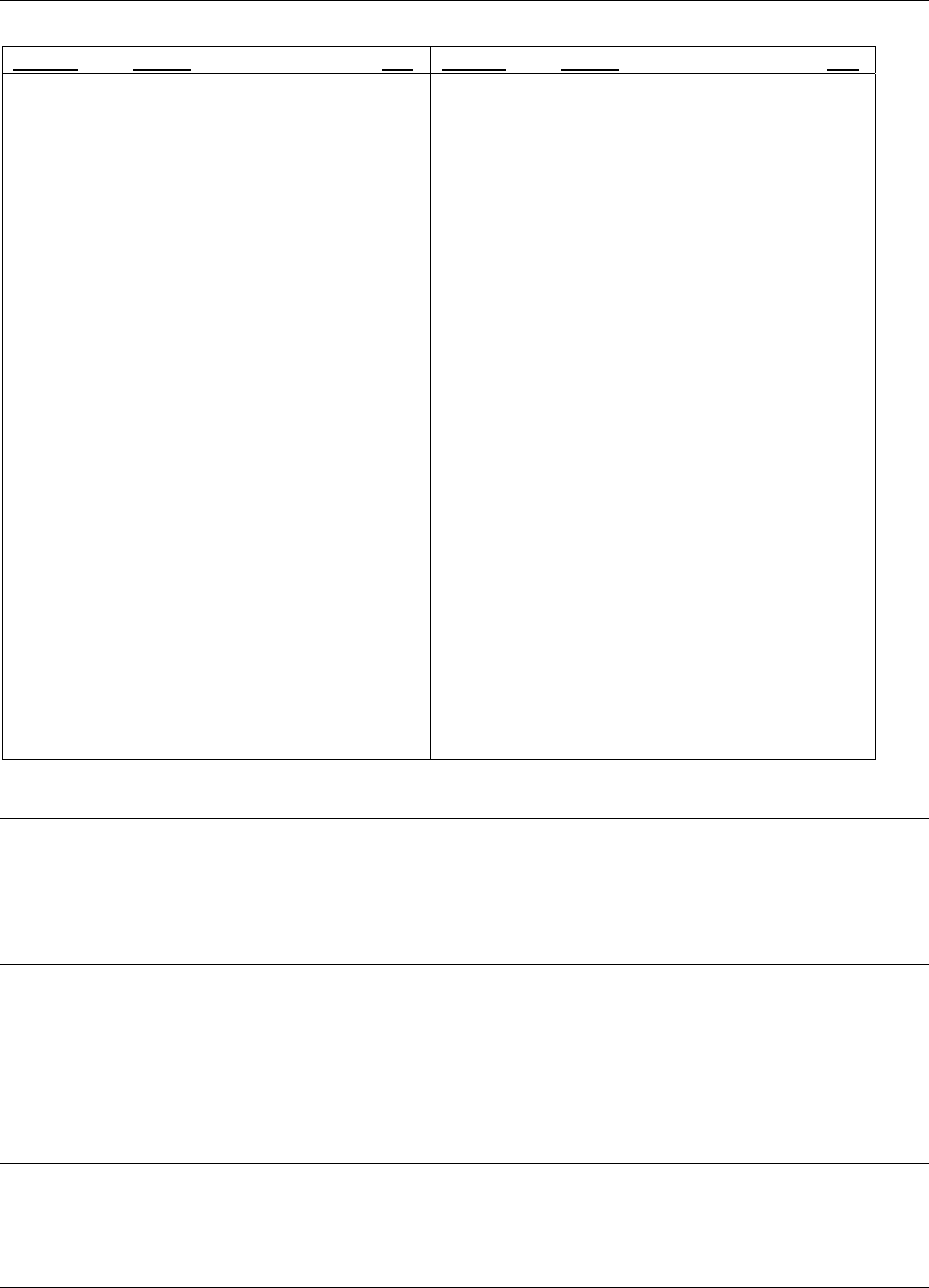
Lake Shore Model 642 Electromagnet Power Supply User’s Manual
Computer Interface Operation 5-29
Table 5-9. Command Summary
Command Function Page Command Function ......................................................Page
*CLS Clear Interface Cmd ..................................29 INTWR? Internal Water Mode Query ........................33
*ESE Event Status Enable Cmd..........................29 KEYST? Keypad Status Query ..................................33
*ESE? Event Status Enable Query........................30 LIMIT Limit Output Settings Cmd.........................34
*ESR? Event Status Register Query ..................... 30 LIMIT? Limit Output Settings Query.......................33
*IDN? Identification Query .................................. 30 LOCK Keypad Lock Cmd ......................................34
*OPC Operation Complete Cmd .........................30 LOCK? Keypad Lock Query....................................34
*OPC? Operation Complete Query .......................30 MAGWTR Magnet Water Mode Command..................34
*RST Reset Instrument Cmd...............................30 MAGWTR? Magnet Water Mode Query ........................34
*SRE Service Request Enable Cmd ....................31 MODE IEEE Interface Mode Cmd..........................34
*SRE? Service Request Enable Query..................31 MODE? IEEE Interface Mode Query .......................34
*STB? Status Byte Query .....................................31 OPST? Operational Status Query............................35
*TST? Self-Test Query.........................................31 OPSTE Operational Status Enable Cmd ..................35
*WAI Wait-To-Continue Cmd ............................31 OPSTE? Operational Status Enable Query................35
BAUD RS-232C Baud Rate Cmd .........................31 OPSTR? Operational Status Register Query..............35
BAUD? RS-232C Baud Rate Query .......................31 RATE Current Ramp Rate Setting Cmd ................35
DFLT Factory Defaults Cmd ...............................32 RATE? Current Ramp Rate Setting Query ..............35
DISP Display Parameter Cmd ............................32 RDGI? Current Output Reading Query...................35
DISP? Display Parameter Query ..........................32 RDGV? Output Voltage Reading Query...................36
ERCL Error Clear Cmd........................................32 RSEG Ramp Segments Enable Cmd......................36
ERST? Error Status Query ....................................32 RSEG? Ramp Segments Enable Query ...................36
ERSTE Error Status Enable Cmd...........................32 RSEGS Ramp Segments Parameters Cmd ...............36
ERSTE? Error Status Enable Query ........................ 32 RSEGS? Ramp Segments Parameters Query.............36
ERSTR? Error Status Register Query ......................33 SETI Output Current Setting Cmd .......................36
IEEE IEEE-488 Interface Parameter Cmd..........33 SETI? Output Current Setting Query .....................36
IEEE? IEEE-488 Interface Parameter Query........33 STOP Stop Output Current Ramp Cmd.................37
INTWR Internal Water Mode Command ..............33 XPGM External Program Mode Cmd .....................37
XPGM? External Program Mode Query ...................37
5.3.1 Interface Commands (Alphabetical Listing)
*CLS Clear Interface Command
Input: *CLS[term]
Remarks: Clears the bits in the Status Byte Register and Standard Event Status Register and terminates all
pending operations. Clears the interface, but not the instrument. The related instrument command
is *RST.
*ESE Standard Event Status Enable Register Command
Input: *ESE <bit weighting>[term]
Format: nnn
Remarks: The Standard Event Status Enable Register determines which bits in the Standard Event Status
Register will set the summary bit in the Status Byte. This command programs the enable register using
a decimal value that corresponds to the binary-weighted sum of all bits in the register. Refer to
Paragraph 5.1.4.2.1.

Lake Shore Model 642 Electromagnet Power Supply User’s Manual
5-30 Computer Interface Operation
*ESE? Standard Event Status Enable Register Query
Input: *ESE?[term]
Returned: <bit weighting>[term]
Format: nnn (Refer to command for description)
*ESR? Standard Event Status Register Query
Input: *ESR?[term]
Returned: <bit weighting>
Format: nnn
Remarks: Bits in this register correspond to various system events and latch when the event occurs. When an
event bit is set, subsequent events corresponding to that bit are ignored. Set bits remain latched until
the register is reset by this query or a *CLS command. Refer to Paragraph 5.1.4.2.1.
*IDN? Identification Query
Input: *IDN?[term]
Returned: <manufacturer>,<model>,<serial>,<firmware version>[term]
Format: aaaa,aaaaaaaa,aaaaaaa,n.n/n.n
<manufacture> Manufacturer ID
<model> Instrument model number
<serial> Serial number
<firmware version> Instrument firmware version, main firmware/DAC firmware.
Example: LSCI,MODEL642,1234567,1.0/1.0
*OPC Operation Complete Command
Input: *OPC[term]
Remarks: Used in conjunction with bit 0 (OPC of the Standard Event Status Register. If sent as the last command
in a command sequence, bit 0 will be set when the instrument completes the operation that was
initiated by the command sequence. Refer to Paragraph 5.1.4.4.6 for more information.
*OPC? Operation Complete Query
Input: *OPC?[term]
Returned: 1[term]
Remarks: Has no interaction with bit 0 (OPC) of the Standard Event Status Register. If sent at the end of a
command sequence, the bus will be held until the instrument completes the operation that was initiated
by the command sequence. Once the sequence is complete a 1 will be placed in the output buffer.
Refer to Paragraph 5.1.4.4.6 for more information.
*RST Reset Instrument Command
Input: *RST[term]
Remarks: Sets controller parameters to power-up settings. Use the DFLT command to set factory defaults.

Lake Shore Model 642 Electromagnet Power Supply User’s Manual
Computer Interface Operation 5-31
*SRE Service Request Enable Register Command
Input: *SRE <bit weighting>[term]
Format: nnn
Remarks: The Service Request Enable Register determines which summary bits of the Status Byte may set bit 6
(RQS/MSS) of the Status Byte to generate a Service Request. This command programs the enable
register using a decimal value that corresponds to the binary-weighted sum of all bits in the register.
Refer to Paragraph 5.1.4.4.
*SRE? Service Request Enable Register Query
Input: *SRE?[term]
Returned: <bit weighting>[term]
Format: nnn (Refer to command for description)
*STB? Status Byte Query
Input: *STB?[term]
Returned: <bit weighting>[term]
Format: nnn
Remarks: This command is similar to a Serial Poll except it is processed like any other instrument command. It
returns the same result as a Serial Poll except that the Status Byte bit 6 (RQS/MSS) is not cleared.
Refer to paragraph 5.1.4.4.4
*TST? Self-Test Query
Input: *TST?[term]
Returned: <status>[term]
Format: n
<status> 0 = No errors found, 1 = Errors found
Remarks: The Model 642 reports status based on test done at power up.
*WAI Wait-to-Continue Command
Input: *WAI[term]
Remarks: This command is not supported in the Model 642.
BAUD RS-232C Baud Rate Command
Input: BAUD <bps>[term]
Format: n
<bps> Specifies Baud rate: 0 = 9600 Baud, 1 = 19200 Baud, 2 = 38400 Baud, 3 = 57600 Baud.
BAUD? RS-232C Baud Rate Query
Input: BAUD?[term]
Returned: <bps>[term]
Format: n (Refer to command for description)

Lake Shore Model 642 Electromagnet Power Supply User’s Manual
5-32 Computer Interface Operation
DFLT Factory Defaults Command
Input: DFLT 99[term]
Remarks: Sets all configuration values to factory defaults and resets the instrument. The instrument must be at
zero amps for this command to work. The "99" is included to prevent accidentally setting the unit to
defaults.
DISP Display Parameter Command
Input: DISP <brightness> [term]
Format: n
<brightness> Specifies display brightness: 0 = 25%, 1 = 50%, 2 = 75%, 3 = 100%.
DISP? Display Parameter Query
Input: DISP? [term]
Returned: <brightness> [term]
Format: n (Refer to command for definition).
ERCL Error Clear Command
Input: ERCL [term]
Remarks: This command will clear the operational errors. The errors will only be cleared if the error conditions
have been removed. Hardware errors can never be cleared. Refer to Paragraph 5.1.4.3 for a list of error
bits.
ERST? Error Status Query
Input: ERST? [term]
Returned: <hardware errors>, <operational errors> [term]
Format: nnn,nnn
Remarks: The integers returned represent the sum of the bit weighting of the error bits. Refer to
Paragraph 5.1.4.3 for a list of error bits. Use the ERRCL command to clear the operational errors.
Hardware errors cannot be cleared.
ERSTE Error Status Enable Command
Input: ERSTE <hardware errors>, <operational errors> [term]
Format: nnn,nnn
Remarks: Each bit has a bit weighting and represents the enable/disable mask of the corresponding error bits in
the Error Status Register. This determines which status bits can set the corresponding summary bits in
the Status Byte Register. To enable an error bit, send the command ERSTE with the sum of the bit
weighting for each desired bit. Refer to Paragraph 5.1.4.3 for a list of error bits.
ERSTE? Error Status Enable Query
Input: ERSTE?[term]
Returned: <hardware errors>, <operational errors> [term]
Format: nnn,nnn Refer to Paragraph 5.1.4.3 for a list of error bits.

Lake Shore Model 642 Electromagnet Power Supply User’s Manual
Computer Interface Operation 5-33
ERSTR? Error Status Register Query
Input: ERSTR? [term]
Returned: <hardware errors>, <operational errors> [term]
Format: nnn,nnn
Remarks: The integers returned represent the sum of the bit weighting of the error bits. These error bits are
latched when an error condition is detected. This register is cleared when it is read. Refer to
Paragraph 5.1.4.3 for a list of error bits. Use the ERRCL command to clear the operational errors.
Hardware errors cannot be cleared.
IEEE IEEE-488 Interface Parameter Command
Input: IEEE <terminator>, <EOI enable>, <address>[term]
Format: n,n,nn
<terminator> Specifies the terminator. Valid entries: 0 = <CR><LF>,1 = <LF><CR>,
2 = <LF>, 3 = No terminator (must have EOI enabled).
<EOI enable> Sets EOI mode: 0 = Enabled, 1 = Disabled.
<address> Specifies the IEEE address: 1 – 30. (Address 0 and 31 are reserved.)
Example: IEEE 0,0,4[term] – After receipt of the current terminator, the instrument uses <CR><LF> as the
new terminator, uses EOI mode, and responds to address 4.
IEEE? IEEE-488 Interface Parameter Query
Input: IEEE?[term]
Returned: <terminator>, <EOI enable>, <address>[term]
Format: n,n,nn (Refer to command for description)
<mode> 0 = Manual Off, 1 = Manual On, 2 = Auto, 3 = Disabled
INTWTR Internal Water Mode Command
Input: INTWTR <mode> [term]
Format: n
<mode> 0 = Manual Off, 1 = Manual On, 2 = Auto, 3 = Disabled
Example: INTWTR 2[term] – Places the internal water mode to Auto, which will automatically control the
power supply water valve based on the internal power dissipation and temperature.
INTWTR? Internal Water Mode Query
Input: INTWTR? [term]
Returned: <mode>[term]
Format: n (Refer to command for description)
KEYST? Keypad Status Query
Input: KEYST?[term]
Returned: <code>[term]
Format: nn
Remarks: Returns a number descriptor of the last key pressed since the last KEYST?.
Returns “01” after initial power-up. Returns “00” if no key pressed since last query.

Lake Shore Model 642 Electromagnet Power Supply User’s Manual
5-34 Computer Interface Operation
LIMIT Limit Output Settings Command
Input: LIMIT <current>, <rate> [term]
Format: +nn.nnnn, +nn.nnnn
<current> Specifies the maximum output current setting allowed: 0 – 70.1000 A.
<rate> Specifies the maximum output current ramp rate setting allowed: 0.0001 – 99.999 A/s.
Remarks: Sets the upper setting limits for output current, compliance voltage, and output current ramp rate. This
is a software limit that will limit the settings to these maximum values.
LIMIT? Limit Output Settings Query
Input: LIMIT? [term]
Returned: <current>, <rate> [term]
Format: +nn.nnnn, +nn.nnnn (Refer to command for description)
LOCK Keypad Lock Command
Input: LOCK <state>, <code>[term]
Format: n,nnn
<state> 0 = Unlock, 1 = Lock All, 2 = Lock Limits.
<code> Specifies lock-out code. Valid entries are 000 – 999.
Remarks: Locks out all front panel entries operations.
Example: LOCK 1,123[term] – Enables keypad lock and sets the code to 123.
LOCK? Keypad Lock Query
Input: LOCK?[term]
Returned: <state>, <code>[term]
Format: n,nnn (Refer to command for description)
MAGWTR Magnet Water Mode Command
Input: MAGWTR <mode>[term]
Format: n
<mode> 0 = Manual Off, 1 = Manual On, 2 = Auto, 3 = Disabled.
Example: MAGWTR 2[term] – Places the magnet water mode to Auto, which will automatically control the
magnet water valve based on the calculated output power.
MAGWTR? Magnet Water Mode Query
Input: MAGWTR?[term]
Returned: <mode>[term]
Format: n (Refer to command for description)
MODE IEEE Interface Mode Command
Input: MODE <mode>[term]
Format: n
<mode> 0 = Local, 1 = Remote, 2 = Remote with local lockout.
Example: MODE 2[term] – Places the Model 642 into remote mode with local lockout.
MODE? IEEE Interface Mode Query
Input: MODE?[term]
Returned: <mode>[term]
Format: n (Refer to command for description)

Lake Shore Model 642 Electromagnet Power Supply User’s Manual
Computer Interface Operation 5-35
OPST? Operational Status Query
Input: OPST? [term]
Returned: <bit weighting> [term]
Format: nnn
Remarks: The integer returned represents the sum of the bit weighting of the operational status bits. Refer to
Paragraph 5.1.4.2.2 for a list of operational status bits.
OPSTE Operational Status Enable Command
Input: OPSTE <bit weighting> [term]
Format: nnn
Remarks: Each bit has a bit weighting and represents the enable/disable mask of the corresponding operational
status bit in the Operational Status Register. This determines which status bits can set the
corresponding summary bit in the Status Byte Register. To enable a status bit, send the command
OPSTE with the sum of the bit weighting for each desired bit. Refer to Paragraph 5.1.4.2.2 for a list
of operational status bits.
OPSTE? Operational Status Enable Query
Input: OPSTE?[term]
Returned: <bit weighting> [term]
Format: nnn Refer to Paragraph 5.1.4.2.2 for a list of operational status bits.
OPSTR? Operational Status Register Query
Input: OPSTR? [term]
Returned: <bit weighting> [term]
Format: nnn
Remarks: The integers returned represent the sum of the bit weighting of the operational status bits. These status
bits are latched when the condition is detected. This register is cleared when it is read. Refer to
Paragraph 5.1.4.2.2 for a list of operational status bits.
RATE Output Current Ramp Rate Setting Command
Input: RATE <rate> [term]
Format: +n.nnnn
<rate> Specifies the rate at which the current will ramp at when a new output current setting is
entered: 0.0001 – 99.999 A/s.
Remarks: Sets the output current ramp rate. This value will be used in both the positive and negative directions.
Setting value is limited by LIMIT.
RATE? Output Current Ramp Rate Setting Query
Input: RATE? [term]
Returned: <rate> [term]
Format: +n.nnnn (Refer to command for description)
RDGI? Current Output Reading Query
Input: RDGI? [term]
Returned: <current> [term]
Format: ±nn.nnnn
<current> Actual measured output current.

Lake Shore Model 642 Electromagnet Power Supply User’s Manual
5-36 Computer Interface Operation
RDGV? Output Voltage Reading Query
Input: RDGV? [term]
Returned: <voltage> [term]
Format: ±n.nnnn
<voltage> Actual output voltage measured at the power supply terminals.
RSEG Ramp Segments Enable Command
Input: RSEG <enable> [term]
Format: n [term]
<enable> Specifies if ramp segments are to be used: 0 = Disabled, 1 = Enabled.
Remarks: Ramp segments are used to change the output current ramp rate based on the output current. Ramp
segments need to be setup first using the RSEGS command.
RSEG? Ramp Segments Enable Query
Input: RSEG? [term]
Returned: <enable> [term]
Format: n (Refer to command for description)
RSEGS Ramp Segments Parameters Command
Input: RSEGS <segment>, <current>, <rate> [term]
Format: n, +nn.nnnn, +n.nnnn [term]
<segment> Specifies the ramp segment to be modified: 1 – 5.
<current> Specifies the upper output current setting that will use this segment:
0.0000 – +70.1000A.
<rate> Specifies the rate at which the current will ramp at when the output current is in this
segment: 0.0001 – 99.999 A/s.
Remarks: Ramp segments are used to change the output current ramp rate based on the output current. The ramp
segment feature needs to be turned on using the RSEG command.
RSEGS? Ramp Segments Parameters Query
Input: RSEGS? <segment>[term]
Returned: <current>, <rate> [term]
Format: +nn.nnnn, +n.nnnn (Refer to command for description)
SETI Output Current Setting Command
Input: SETI <current> [term]
Format: ±nn.nnnn
<current> Specifies the output current setting: 0.0000 – ±70.1000A.
Remarks: Sets the current value that the output will ramp to at the present ramp rate.
Setting value is limited by LIMIT.
SETI? Output Current Setting Query
Input: SETI? [term]
Returned: <current> [term]
Format: ±nn.nnnn (Refer to command for description)

Lake Shore Model 642 Electromagnet Power Supply User’s Manual
Computer Interface Operation 5-37
STOP Stop Output Current Ramp Command
Input: STOP [term]
Remarks: This command will stop the output current ramp within two seconds of sending the command.
To restart the ramp, use the SETI command to set a new output current setpoint.
XPGM External Program Mode Command
Input: XPGM <mode>[term]
Format: n
<mode> 0 = Internal, 1 = External, 2 = Sum.
Example: XPGM 1[term] – Places the Model 642 into external program mode where the output current is set by
an external voltage.
XPGM? External Program Mode Query
Input: XPGM?[term]
Returned: <mode>[term]
Format: n (Refer to command for description)

Lake Shore Model 642 Electromagnet Power Supply User’s Manual
5-38 Computer Interface Operation
This Page Intentionally Left Blank
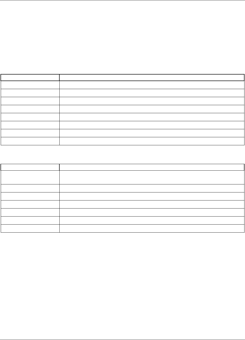
Lake Shore Model 642 Electromagnet Power Supply User’s Manual
Options and Accessories 6-1
CHAPTER 6
OPTIONS AND ACCESSORIES
6.0 GENERAL
This chapter provides information on accessories available for the Model 642 Electromagnet Power Supply.
6.1 ACCESSORIES INCLUDED
Part Number Description
MAN-Model 642 Model 642 Electromagnet Power Supply User’s Manual.
6031 Two front handles.
6032 Two rear handles.
6051 Terminal Block, 4 Pin
6052 Terminal Block, 8 Pin
6252 15-pin D-sub mating connector, analog I/O.
108-654 Strain Relief Bushing Kit
– Calibration Certificate.
6.2 ACCESSORIES AVAILABLE
Part Number Description
6201 IEEE-488 Cable Kit, 1 meter (3 foot) IEEE-488 (GPIB) computer interface cable
assembly.
6261 Magnet Cable Kit, 3 meters (10 feet), 60 A, AWG 4.
6262 Magnet Cable Kit, 6 meters (20 feet), 60 A, AWG 4.
6041 Flow Switch.
6042 Solenoid Water Valve with Bracket.
CAL-642-CERT Instrument recalibration with certificate.
CAL-642-DATA Instrument recalibration with certificate and data.

Lake Shore Model 642 Electromagnet Power Supply User’s Manual
6-2 Options and Accessories
This Page Intentionally Left Blank
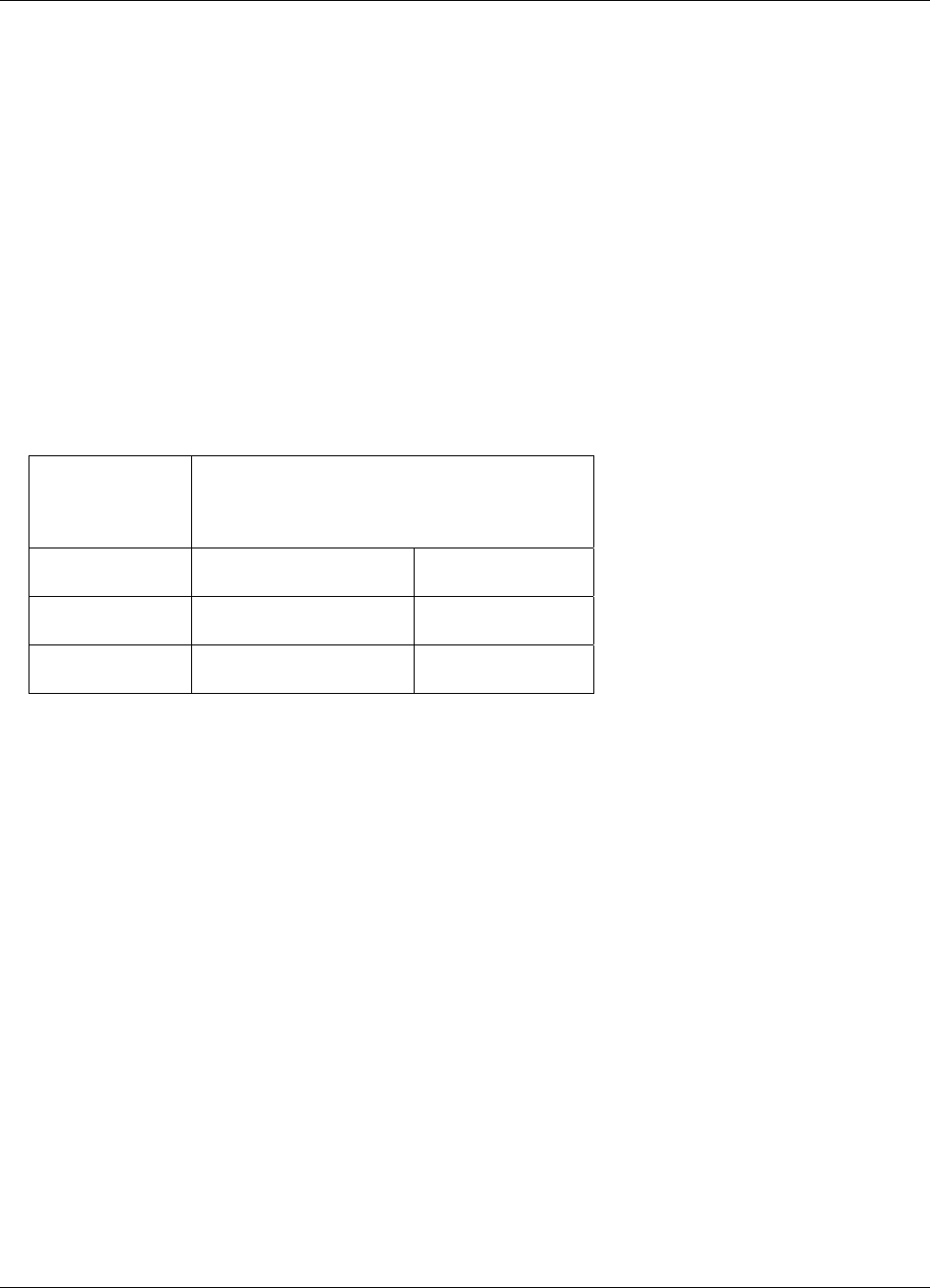
Lake Shore Model 642 Electromagnet Power Supply User’s Manual
Service 7-1
CHAPTER 7
SERVICE
7.0 GENERAL
This chapter provides basic service information for the Model 642 Superconducting Magnet Power Supply. Customer
service of the product is limited to the information presented in this chapter. Factory trained service personnel should be
consulted if the instrument requires repair.
7.1 CONTACTING LAKE SHORE CRYOTRONICS
If a Lake Shore product was purchased through a dealer or representative, please use that resource for prompt sales or
service information. When contacting Lake Shore directly, please specify the name of a department if do not know the
name of an individual. Questions regarding product applications, price, availability and shipments should be directed to
sales. Questions regarding instrument calibration or repair should be directed to instrument service. Do not return a
product to Lake Shore without a Return Authorization number. Refer to Paragraph 7.2. Current contact information
can always be found on the Lake Shore web site: www.lakeshore.com.
Mailing Address:
Lake Shore Cryotronics, Inc.
Instrument Service Department
575 McCorkle Blvd.
Westerville, OH USA 43082-8888
E-mail Address: sales@lakeshore.com
service@lakeshore.com
Sales
Instrument Service
Telephone: 614-891-2244
614-891-2243 ext. 131
Sales
Instrument Service
Fax: 614-818-1600
614-818-1609
Sales
Instrument Service
When contacting Lake Shore please provide your name and complete contact information including e-mail address if
possible. It is often helpful to include the instrument model number and serial number (located on the rear panel of the
instrument) as well as the firmware revision information as described in Paragraph 4.21.
7.2 RETURNING PRODUCTS TO LAKE SHORE
If it is necessary to return the Model 642 for recalibration, repair or replacement, a Return Authorization (RA) number
must be obtained from a factory representative or from the Lake Shore web site. Do not return a product to Lake
Shore without an RA number. The following information must be provided to Lake Shore in order to obtain an RA
number.
1. Instrument model and serial number.
2. User name, company, address, phone number, and e-mail address.
3. Malfunction symptoms.
4. Description of the system in which the product is used.
If possible, the original packing material should be retained for reshipment. If not available, a minimum of three inches
of shock adsorbent packing material should be placed snugly on all sides of the instrument placed in a sturdy corrugated
cardboard box. The RA number should be included in the mailing label or written prominently on the outside of the box.
A copy of the customer contact information and RA number should be included inside the box. Consult Lake Shore with
questions regarding shipping and packing instructions.
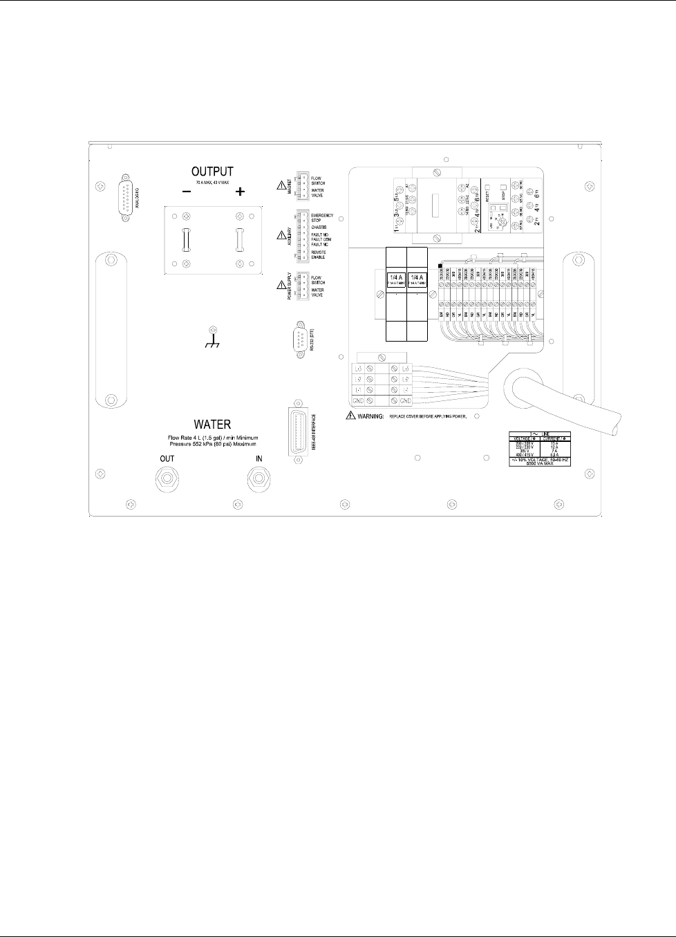
Lake Shore Model 642 Electromagnet Power Supply User’s Manual
7-2 Service
7.3 LINE VOLTAGE SELECTION
The Model 642 may be configured for four basic AC power configurations: 208 VAC, 230 VAC, 380 VAC and 415
VAC. Proper voltage selection must be made before connection to the power mains. Each configuration requires the
appropriate wiring within the power wiring access panel on the rear of the instrument. Nominal line voltages and
appropriate selections are shown in Table 7-1. See Section 3.3.1 for further details. See Figure 7-1 for general locations.
Figure 7-1. Model 642 Rear Panel (shown with wiring cover removed)
Use the following procedure to change the instrument line voltage.
WARNING: To avoid potentially lethal shocks, turn off the power supply and disconnect it from AC power before
performing this procedure.
1. Identify the power wiring access panel on the rear of the Model 642.
2. Turn the front panel line power switch OFF (O).
3. Disconnect the power cable at the plug end for safety.
4. Remove the perimeter screws holding the power wiring access panel.
5. Observe the 4 voltage-selection wires held by the clear plastic wiring guide. See Figure 7-2.
6. Loosen the screw terminals presently holding the four wires.
7. Relocate the 4 wires (using the wiring guide) to the desired voltage position. Refer to Table 7-1.
8. Place the wires into the appropriate screw terminals and tighten.
9. Verify solid, tight screw connections to these four wires.
10. Replace the power wiring access panel using all perimeter screws.
11. Verify the voltage indicator in the window of the power wiring access panel.

Lake Shore Model 642 Electromagnet Power Supply User’s Manual
Service 7-3
TERMINAL SCREW
WIRE FERRULE
VOLTAGE SELECTOR CARD
VOLTAGE INDICATOR KEY
Figure 7-2. Voltage Change Detail
7.4 CIRCUIT BREAKER SETTING
The main three-phase input power is protected by an automatic-reset circuit breaker within the instrument. A smaller,
start-up power supply is fused separately and discussed in Section 7.5. If the breaker trips, it will reset within a few
minutes and the unit can be restarted. If the unit trips again after a short time, the circuit breaker trip current may be set
incorrectly. Table 7-1 shows required voltage and current settings.
Table 7-1. Voltage and Current Selection
Nominal Voltage Voltage Tap Circuit Breaker
200 V 204 V 18 A
208 V 204 V 18 A
220 V 225 V 17 A
230 V 225 V 17 A
380 V 380 V 12 A
400 V 408 V 12 A
415 V 408 V 12 A
WARNING: To avoid potentially lethal shocks, turn off the power supply and disconnect it from AC power before
performing this procedure.
CAUTION: For continued protection against fire hazard, use only the recommended current setting for the line
voltage selected.
Use the following procedure to verify or change the circuit breaker current setting.
1. Identify the power wiring access panel on the rear of the Model 642.
2. Turn the front panel line power switch OFF (O).
3. Disconnect the power cable at the plug end for safety.
4. Remove the perimeter screws holding the power wiring access panel.
5. Refer to Figure 7-1 to locate the circuit breaker detailed in Figure 7-3.
6. Lift the circuit breaker setting access door and visually confirm the setting as shown in Figure 7-3.
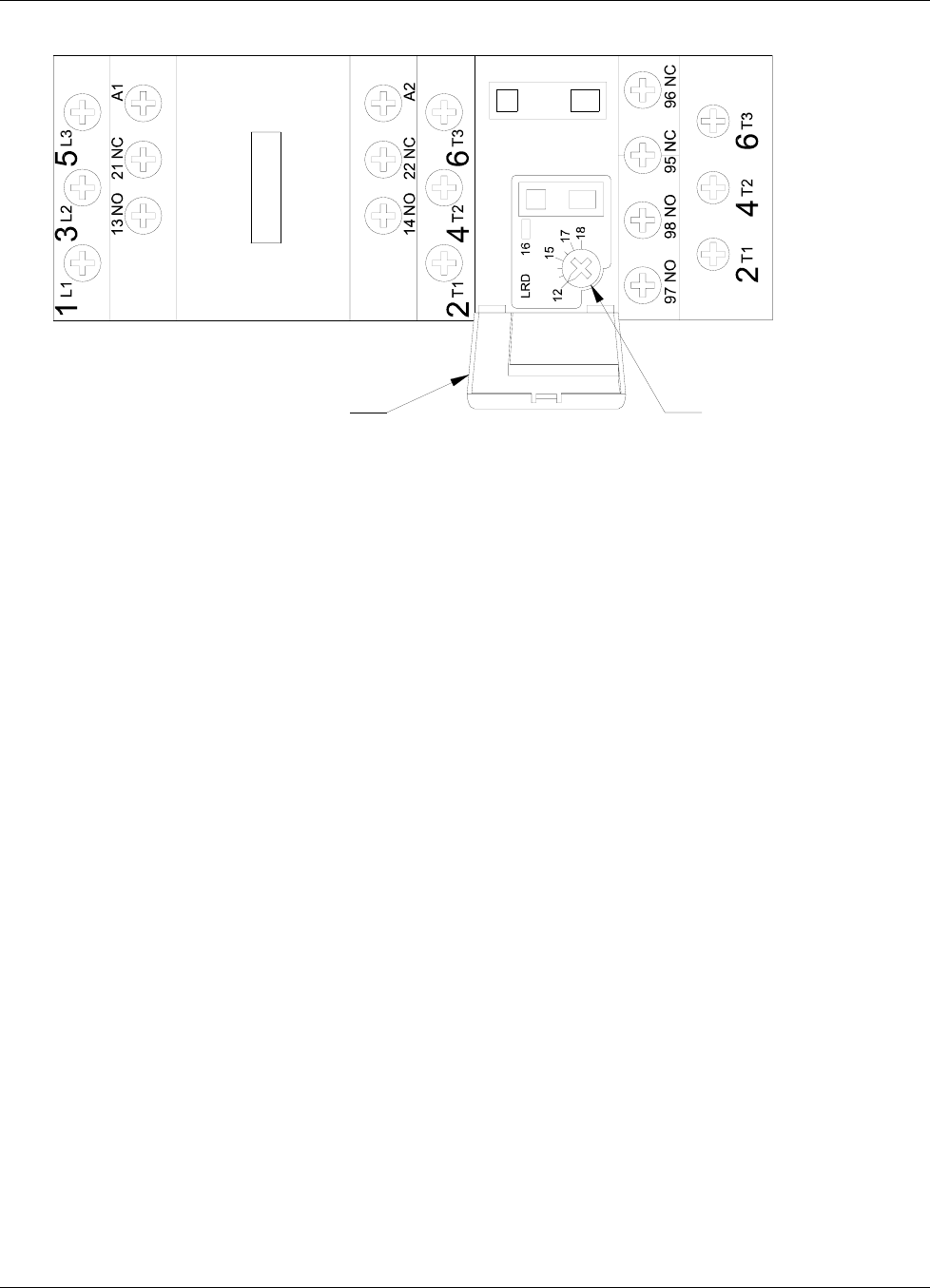
Lake Shore Model 642 Electromagnet Power Supply User’s Manual
7-4 Service
CURRENT SETTING DIALACCESS COVER
Figure 7-3. Circuit Breaker
7. If incorrect, use a small straight blade screwdriver to reset according to Table 7-1.
8. Close the circuit breaker access door.
9. Replace the power wiring access panel using all perimeter screws.
7.5 POWER LINE FUSE REPLACEMENT
The Model 642 uses a low-power, start-up power supply to provide power to the main contactor coil through multiple
thermal safety switches. The start-up supply is energized any time the three-phase power input voltage is connected to
the Model 642. This section deals with the fuses for this supply. If the power line fuses for this supply are open, the
Model 642 internal three-phase contactor will not close and normal operation will not be possible. If the Model 642 is
connected to an input voltage that is higher than the selected voltage of the Model 642, these fuses are expected to clear
and prevent operation of the Model 642. Proper voltage selection must be made before connection to the power mains.
Access to these fuses is through the power wiring access panel.
WARNING: To avoid potentially lethal shocks, turn off the power supply and disconnect it from AC power before
performing this procedure.
CAUTION: For continued protection against fire hazard, replace only with same fuse type and rating specified for
the line voltage selected.
Use the following procedure to change the power line fuses.
1. Identify the power wiring access panel on the rear of the Model 642.
2. Turn the front panel line power switch OFF (O).
3. Disconnect the power cable at the plug end for safety.
4. Remove the perimeter screws holding the power wiring access panel.
5. Locate the two fuse holder assemblies as shown in Figure 7-1 and detailed in Figure 7-4
6. Pull open the access door to remove a fuse.
7. Check the fuse for continuity. Replace fuse(s) if necessary. Fuses should be replaced in pairs. Fuses are inserted
small-end first as shown.
8. Close the fuse access door(s).
9. Replace the wiring access panel using all perimeter screws.
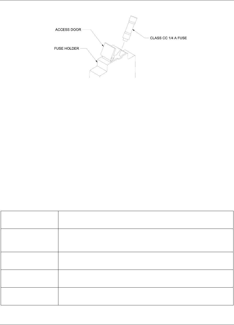
Lake Shore Model 642 Electromagnet Power Supply User’s Manual
Service 7-5
Figure 7-4. Fuse Holder Detail
7.6 ERROR MESSAGES
The following messages appear on the lower part of the instrument display when it identifies a problem during operation.
The Fault LED will light in conjunction with the error message. A more extensive description of the error message can
shown by pressing the Status key. If the error condition can be immediately cleared, it can be done by pressing the
Status key while in the error status display. Refer to Paragraph 4.14 for a description of the error status display.
Error messages are divided into three groups:
Instrument Hardware Errors are related to internal instrument circuitry. When one of these errors occurs, the Fault
LED is solidly lit, the output setting is set to 0 A, current entry will not be allowed and there is no way to clear the
error unless power is cycled. If one of these error messages persists after power is cycled, the instrument requires
repair. Instrument Hardware Errors are listed in Table 7-2.
Operational Errors are related to instrument operation and do not necessarily indicate a hardware problem. When one
of theses errors occurs, the Fault LED will be blinking and the error condition can be cleared once the fault condition
has been removed. Operational Errors are listed in Table 7-3.
User Errors are related to user requests that cannot be processed. These errors generate responses that immediately
explain the cause of the error. These are usually simple order-of-operation issues and are easily resolved. The fault
LED is not used for these simpler errors. User Errors are self-explanatory and are therefore not listed.
Table 7-2. Instrument Hardware Errors
Internal Temperature Fault
Cold Plate temperature is over 45° C. The output setting is set to 0 A and no current
entry will be allowed. The error message will flash for 10 seconds then the Model 642
will turn itself off.
Output Over Voltage
The output voltage is greater than the 44 V compliance voltage limit indicating a
problem with the compliance voltage circuitry. The output setting is set to 0 A and no
current entry will be allowed. The error message will flash for 10 seconds then the
Model 642 will turn itself off.
Output Over Current
The measured output current exceeded 73 A. The output setting is set to 0 A and no
current entry will be allowed. The error message will flash for 10 seconds then the
Model 642 will turn itself off.
DAC Processor not
Responding
The processor that controls the output DAC is not responding or is responding
incorrectly. The output setting is set to 0 A and no current entry will be allowed.
Cycle power to attempt to clear.
Output Control Failure
One of the internally monitored voltages is beyond an acceptable range on power up.
The output setting is set to 0 A and no current entry will be allowed. Cycle power to
clear attempt to clear.

Lake Shore Model 642 Electromagnet Power Supply User’s Manual
7-6 Service
Table 7-3. Operational Errors
Remote Enable Fault
Detected
The Remote Enable connection loop is not closed. The output setting is set to 0 A and
no current entry will be allowed. Once the loop is closed, the error is cleared by pressing
the STATUS key or sending “ERCL” over computer interface.
Power Supply Flow
Switch Fault Detected
The Power Supply Flow Switch connection loop is not closed. The output setting is set
to 0 A and no current entry will be allowed. Once the loop is closed, the error is cleared
by pressing the STATUS key or sending “ERCL” over computer interface.
Magnet Flow Switch Fault
Detected
The Magnet Flow Switch connection loop is not closed. The output setting is set to 0 A
and no current entry will be allowed. Once the loop is closed, the error is cleared by
pressing the STATUS key or sending “ERCL” over computer interface.
High Line Voltage
Detected
The Output Stage Voltage (Out Stg V) is greater than 66 V. The most likely cause is a
power mains voltage that is too high. This error will clear when the power mains voltage
is within specified tolerances. Continued operation is allowed but may not be optimal.
Low Line Voltage
Detected
The Output Stage Voltage (Out Stg V) is less than 44 V. The most likely cause is a
power mains voltage that is too low. This error will clear when the power mains voltage
is within specified tolerances. Continued operation is allowed but may not be optimal.
Internal Temperature High
Cold Plate temperature is over 40° C. The output setting is set to 0 A and no current
entry will be allowed. The error will clear when the Cold Plate temperature falls below
40° C. This may be indicative of low cooling water flow or high water temperature.
External Current Program
Error
The instrument was not allowed to change to external or sum current programming
modes (including power-up) because the programming voltage was greater than
0.025 V. This error can be cleared when the programming voltage is less than 0.025 V
or the instrument is changed to internal current programming mode.
Calibration Invalid
The instrument has either not been calibrated or calibration data has been corrupted.
This error can be cleared at any time by pressing both ESC and ENTER keys on the
keypad simultaneously. The instrument can still be used in this state but there is no
guarantee that it is operating within specifications. The instrument must be recalibrated
to properly correct this error condition.
7.7 ELECTROSTATIC DISCHARGE
Electrostatic Discharge (ESD) may damage electronic parts, assemblies, and equipment. ESD is a transfer of electrostatic
charge between bodies at different electrostatic potentials caused by direct contact or induced by an electrostatic field.
The low-energy source that most commonly destroys Electrostatic Discharge Sensitive (ESDS) devices is the human
body, which generates and retains static electricity. Simply walking across a carpet in low humidity may generate up to
35,000 volts of static electricity.
Current technology trends toward greater complexity, increased packaging density, and thinner dielectrics between
active elements, which results in electronic devices with even more ESD sensitivity. Some electronic parts are more
ESDS than others. ESD levels of only a few hundred volts may damage electronic components such as semiconductors,
thick and thin film resistors, and piezoelectric crystals during testing, handling, repair, or assembly. Discharge voltages
below 4000 volts cannot be seen, felt, or heard.
7.7.1 Identification of Electrostatic Discharge Sensitive Components
The following are various industry symbols used to label components as ESDS.

Lake Shore Model 642 Electromagnet Power Supply User’s Manual
Service 7-7
7.7.2 Handling Electrostatic Discharge Sensitive Components
Observe all precautions necessary to prevent damage to ESDS components before attempting installation. Bring the
device and everything that contacts it to ground potential by providing a conductive surface and discharge paths. As a
minimum, observe these precautions:
1. De-energize or disconnect all power and signal sources and loads used with unit.
2. Place unit on a grounded conductive work surface.
3. Ground the technician through a conductive wrist strap (or other device) using 1 MΩ series resistor to protect
operator.
4. Ground any tools, such as soldering equipment, that will contact unit. Contact with operator's hands provides a
sufficient ground for tools that are otherwise electrically isolated.
5. Place ESDS devices and assemblies removed from a unit on a conductive work surface or in a conductive container.
An operator inserting or removing a device or assembly from a container must maintain contact with a conductive
portion of the container. Use only plastic bags approved for storage of ESD material.
6. Do not handle ESDS devices unnecessarily or remove from the packages until actually used or tested.
7.8 ENCLOSURE TOP PANEL REMOVAL AND REPLACEMENT
WARNING: To avoid potentially lethal shocks, set current output to 0 A, turn off the power supply, and disconnect
it from AC power line before performing this procedure. Only qualified personnel should perform this
procedure.
7.8.1 Removal
1. Set power switch to Off (O) and disconnect power cord from the power outlet.
2. Remove the Model 642 from rack (if necessary) to gain easy access to the top panel.
3. Remove and retain the 17 flat-head Phillips screws securing the top panel of the Model 642.
4. Remove and retain the two truss-head Phillips screws and nylon washers from the top edge of the front panel that
secure the top panel to the front panel.
5. Carefully remove the top panel from the unit.
7.8.2 Installation
1. Replace the top panel on the Model 642 with the folded lip of the panel toward the front of the unit.
2. Replace and secure the 17 flat-headed Phillips screws. Do not use excessive torque.
3. Replace the two Phillips head screws securing the top panel lip to the top edge of the front panel.
4. Replace the Model 642 in the rack (if used)
5. Reconnect the Model 642 to the power outlet. Apply power via the front panel button (l).
7.9 FIRMWARE REPLACEMENT
There are two integrated circuits (IC) that may potentially require replacement. See Figure 7-6 for respective locations.
• Main Firmware Erasable Programmable Read Only Memory (EPROM) (U35) – Contains the user interface software.
Has a sticker on top labeled “MModel 642F.HEX” and a date.
• DAC Microcontroller (U51) – Contains software that controls the output DAC. Has a sticker on top labeled “MModel
642DACF.HEX” and a date.
Use the following procedure to replace either or both of these ICs.
1. Follow the top of enclosure removal procedure of Section 7.8.1.
2. Refer to Figure 7-5 and locate the Digital Board assembly.
3. Disconnect the housekeeping transformer connector from J-1.
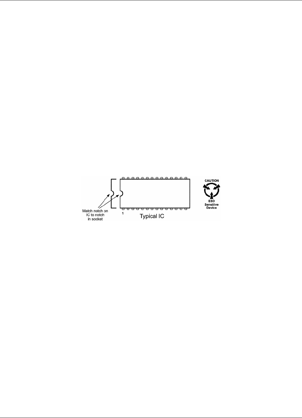
Lake Shore Model 642 Electromagnet Power Supply User’s Manual
7-8 Service
Firmware Replacement (Continued)
4. Disconnect the ribbon cable to the Analog Board assembly from J-2.
5. Disconnect the cable to the fan from J-3.
6. Disconnect the ribbon cable to the Keypad Board assembly from J-4.
7. Disconnect the main transformer connector from J-7.
8. Remove all connections from the IEEE-488, RS232C, Power Supply, Auxiliary, and Magnet Water connectors on
the back of the Model 642.
9. Remove and retain the hexagonal mounting standoffs from the IEEE-488 and RS232C connectors on the back of the
Model 642.
10. Locate, remove and retain the two 6-32 pan-head machine screws holding the Digital Board in place. See Figure 7-6.
11. Remove the Digital Board by pulling it toward the front to clear the rear connectors from their back panel holes and
then carefully lifting the Board assembly out of the unit.
12. Locate the appropriate IC(s) on the main circuit board. See Figure 7-6. Note orientation of existing IC.
CAUTION: The ICs are Electrostatic Discharge Sensitive (ESDS) devices. Wear shock-proof wrist straps (resistor
limited to <5 mA) to prevent injury to service personnel and to avoid inducing an Electrostatic
Discharge (ESD) into the device.
13. Use IC puller to remove existing IC(s) from the socket.
14. Noting orientation of new IC(s), use an IC insertion tool to place new device(s) into socket(s). Ensure that no pins
are allowed to bend.
15. Reinstall the Digital Board into the unit taking care to properly locate the bottom edge of the board between the four
locator pins on the bottom of the instrument. Push the Digital Board carefully rearward taking care to locate the rear
connectors through the rear panel of the unit.
16. Attach the Digital Board using the two 6-32 pan-head Phillips screws removed earlier.
17. Remount the IEEE-488 and RS232C connectors using the hexagonal mounting standoffs removed earlier.
18. Reinstall all appropriate rear panel connections that were removed earlier. Take care NOT to interchange the
“Magnet” and “Power Supply” connectors.
19. Reinstall all Digital Board connections removed earlier. See Figure 7-6
20. Recheck that all connectors have been reinstalled and confirm proper locations and orientations of each.
21. Follow the top of enclosure installation procedure of Section 7.8.2.
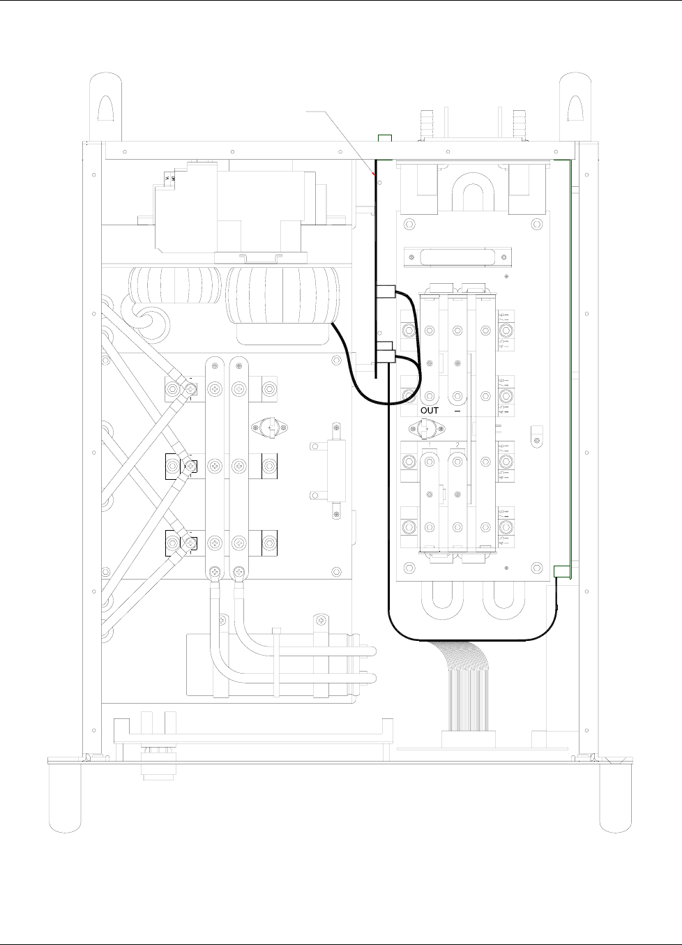
Lake Shore Model 642 Electromagnet Power Supply User’s Manual
Service 7-9
DIGITAL BOARD
Figure 7-5. Board Locations (top view)
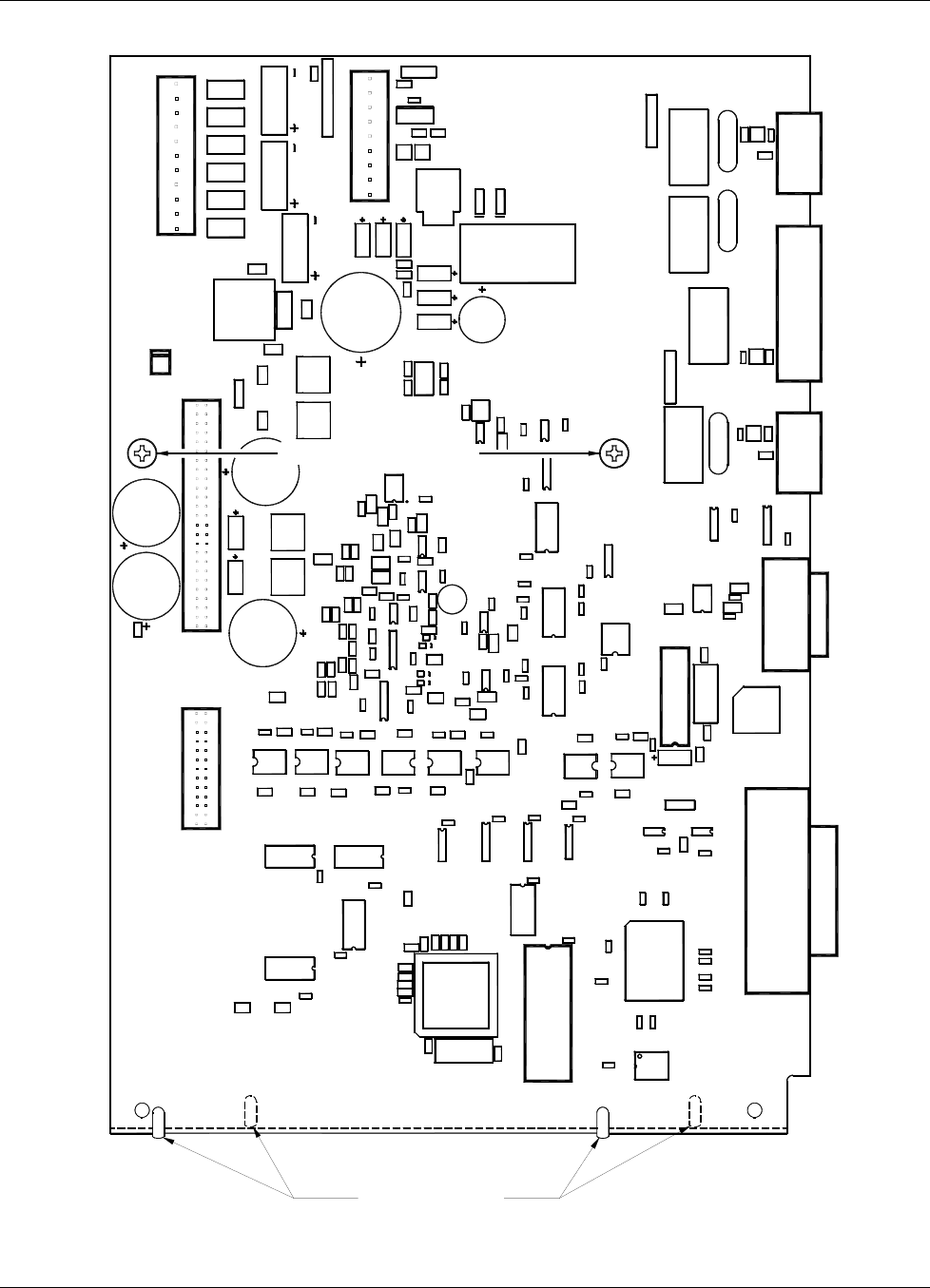
Lake Shore Model 642 Electromagnet Power Supply User’s Manual
7-10 Service
VR1
R74
C67
CR18
L1
AUXILIARY
C131
K3
CR10
R73
K2
VR3
K5
C132
J10
J9
MAGNET
F9
C130
R71
VR2
CR9
R78 J8
LOCATOR PINS
TP6
U13
C43
R52
R23
C29 R32 C21
R22
R29
R17
R28
R18
R24
R13
C30
IRDG
CR4
U15
R45
C45
C62
R55
TP8
CR5
CR6
U16
R46
R48
R42
C63
CR7
C111
C75
U48
C103
C107
J6
U34
C91 C93
C72
U47
U35
C102
C92
C105
U41
U33
C86
IEEE CONNECTOR
C122
C121
C120
C119
C118
C117
C108
C116
U49
R69
C24
R30 R34
C25
GND2
R20
R31
C26
C36TP4
C57
I DAC OUT
U20
C38
C42 R50
C56
C49
R43
C50
TP10
R56
CR3
C40
C53
1
J3
C13
U25
U1
1
F2
C6
U52
C104
C70
U27
R64
A/D 2 IN
TP9
C61
U42
C94
R65
U45
R67
U36
R66
TP7
C87
A/D 1 IN C79 C83
U31
C80
C84
U32
C76
C97 C96
C106
C98
U37
U51
R70
TEST
C112
RUN
JMP1
C109
R54
R53
C23
U9
R41
U21
C54
U26
R8
R11 R10
J4 GND2
U2
KEYPAD PCB
R5 R7
U7
R6
C7
TP2
C10
C3
R14
R12
C44
VRDG
R33
R9
U10
R27
C18 R16
U14
R44
C32
U22
R68
SP1
C124
U46
C125
RS232C
Y2
C114
U50
C127 J5
MOUNTING SCREWS
R58 VREF
F4
HOUSEKEEPING TRANSFORMER SECONDARIES
MAIN TRANSFORMER
1
C8
FAN
R80
R4
R2
J2
C11
U3
C4
C5
U4
C52
ANALOG PCB
C27
U24
U17
C31
C39 TP5
R15
R26
R25
R21
U19
R19
R49
C55
C113
C81
C73
C123
R60
+5(1) GND 1
642 DIGITAL PCB
c 2006 LSCI
111-278 /A
TP3 TP1
C51
Y1
R3
C2
C16
C17
C9
U5
U6
C37
R37
C22
R36
U12
R39
U18
R47
R40
R51
C60
ACAC ACAC
F3
CR1
ACAC
R1
R38
C19
C46
C1
R79
C47
C48
R35
C34
C28
C33
U23
C41
CR17
J1
F6
F5
ACAC
CR2
F1
F7
ACACACAC
R62
J7
R63
C58
CR15
Q1
R61
CR16
R59
F10
F8
U55
U39
C88
C85
U38
C100
C99
C77
U30
C89
C78
C90
U40
C95
K4
SUPPLY
POWER
U53
C126
C128
U54
C129
CR11
R77
Figure 7-6. Digital Board Parts Locations
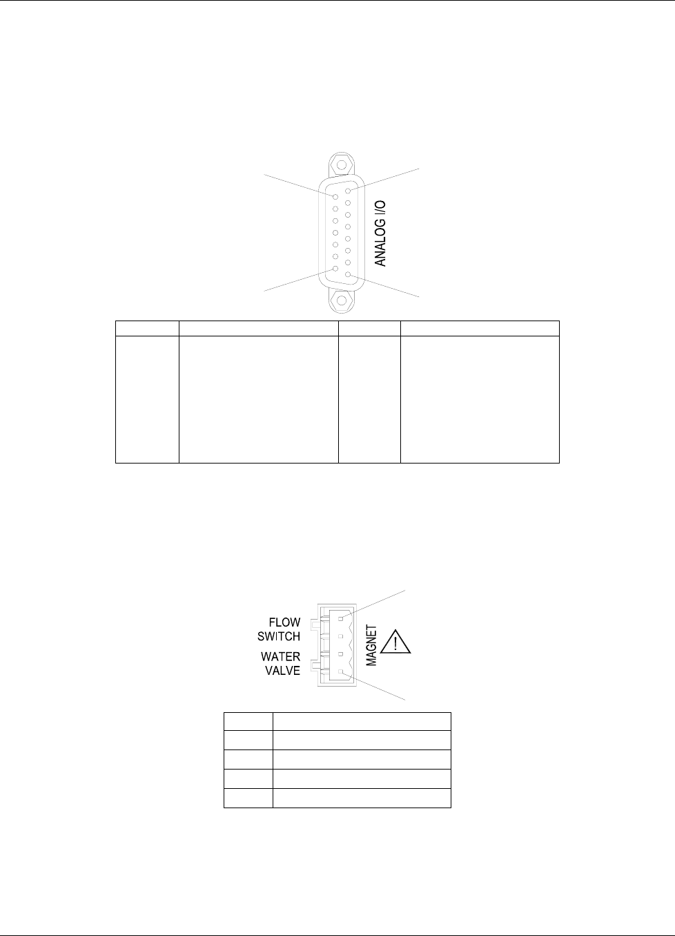
Lake Shore Model 642 Electromagnet Power Supply User’s Manual
Service 7-11
7.10 CONNECTOR AND CABLE DEFINITIONS
All non-power electrical connections to the rear of the Model 642 are detailed in this section.
7.10.1 Analog I/O Connector
The Analog I/O connector provides the connections for the External Programming voltage as well as Analog
representations of the current and voltage output levels. Although these inputs/outputs are electronically balanced to
minimize ground loops, the common-mode voltage should not exceed 5 V on the outputs and 2 V on the input.
1
8
9
15
Pin Name Pin Name
1
2
3
4
5
6
7
8
NC
Chassis-common
Current Program –
Chassis-common
Voltage Monitor –
Chassis-common
Current Monitor –
Chassis-common
9
10
11
12
13
14
15
NC
Chassis-common
Current Program +
Chassis-common
Voltage Monitor +
Chassis-common
Current Monitor +
Figure 7-7. ANALOG I/O Connector Details
7.10.2 Magnet Connector
The Magnet Water connector provides the means to connect a water control valve (24 VAC) and an associated water
flow switch (closed during flow) to protect the magnet from loss of water flow. Pins 1 & 2 must be closed for normal
operation. Pins 3 & 4 supply 24 VAC at 1 A for operation of a water control valve.
4
1
Pin Name
1 Flow Switch (Com)
2 Flow Switch
3 Magnet Water Valve A
4 Magnet Water Valve B
Figure 7-8. Magnet Connector Details
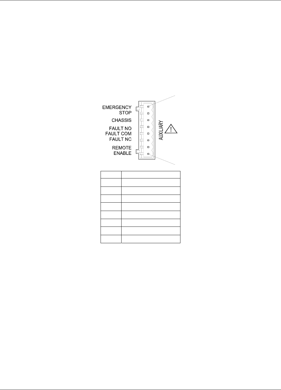
Lake Shore Model 642 Electromagnet Power Supply User’s Manual
7-12 Service
7.10.3 Auxiliary Connector
The Auxiliary Connector provides connections for three functions:
1. Emergency Stop – This normally-closed circuit turns off power to the Model 642 just as if the OFF (O) button was
pressed on the front panel when opened. Normal operation requires a closed connection between the pins.
2. Fault Relay – The fault relay can be used to communicate the presence of a Model 642 fault to external equipment.
The relay follows the operation of the Fault light on the front panel. Both normally-open and normally-closed
configurations are provided. The contacts are electrically isolated from the Model 642 chassis.
3. Remote Enable – These contacts are similar in function to the flow switch inputs. Normal (enabled) operation
requires a closed connection between the pins.
1
8
Pin Name
1 Emergency Stop A
2 Emergency Stop B
3 Chassis-common
4 Fault-NO
5 Fault-Com
6 Fault-NC
7 Chassis-common
8 Remote Enable
Figure 7-9. Auxiliary Connector Details
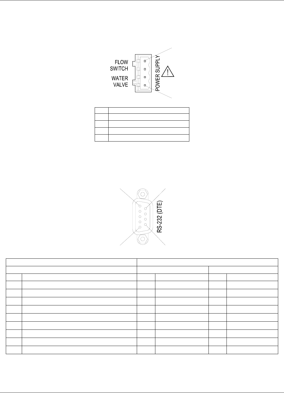
Lake Shore Model 642 Electromagnet Power Supply User’s Manual
Service 7-13
7.10.4 Power Supply Connector
The Power Supply connector provides the means to connect a water control valve (24 VAC) and an associated water
flow switch (closed during flow) to protect the Model 642 from loss of water flow. Pins 1 & 2 must be closed for normal
operation. Pins 3 & 4 supply 24 VAC at 1 A for operation of a water control valve.
4
1
Pin Name
1 Flow Switch (Com)
2 Flow Switch
3 Power Supply Water Valve A
4 Power Supply Water Valve B
Figure 7-10. Power Supply Connector Details
7.10.5 RS-232C Serial Interface Connector
This connector provides one of two means of computer interface. Command descriptions are found in Section 5.
9
6
5
1
Model 642 Electromagnet Power Supply Typical Computers
DE-9P (DTE) DB-25P (DTE) DE-9P (DTE)
Pin Description Pin Description Pin Description
1 NC 2 TD (out) 1 DCD (in)
2 Receive Data (RD in) 3 RD (in) 2 RD (in)
3 Transmit Data (TD out) 4 RTS (out) 3 TD (out)
4 Data Terminal Ready (DTR out) 5 CTS (in) 4 DTR (out)
5 Chassis-common 6 DSR (in) 5 GND
6 Data Set Ready (DSR in) 7 GND 6 DSR (in)
7 Data Terminal Ready (DTR out) (tied to 4) 8 DCD (in) 7 RTS (out)
8 NC 20 DTR (out) 8 CTS (in)
9 NC 22 Ring in (in) 9 Ring in (in)
Figure 7-11. RS232C (DTE) Connector Details
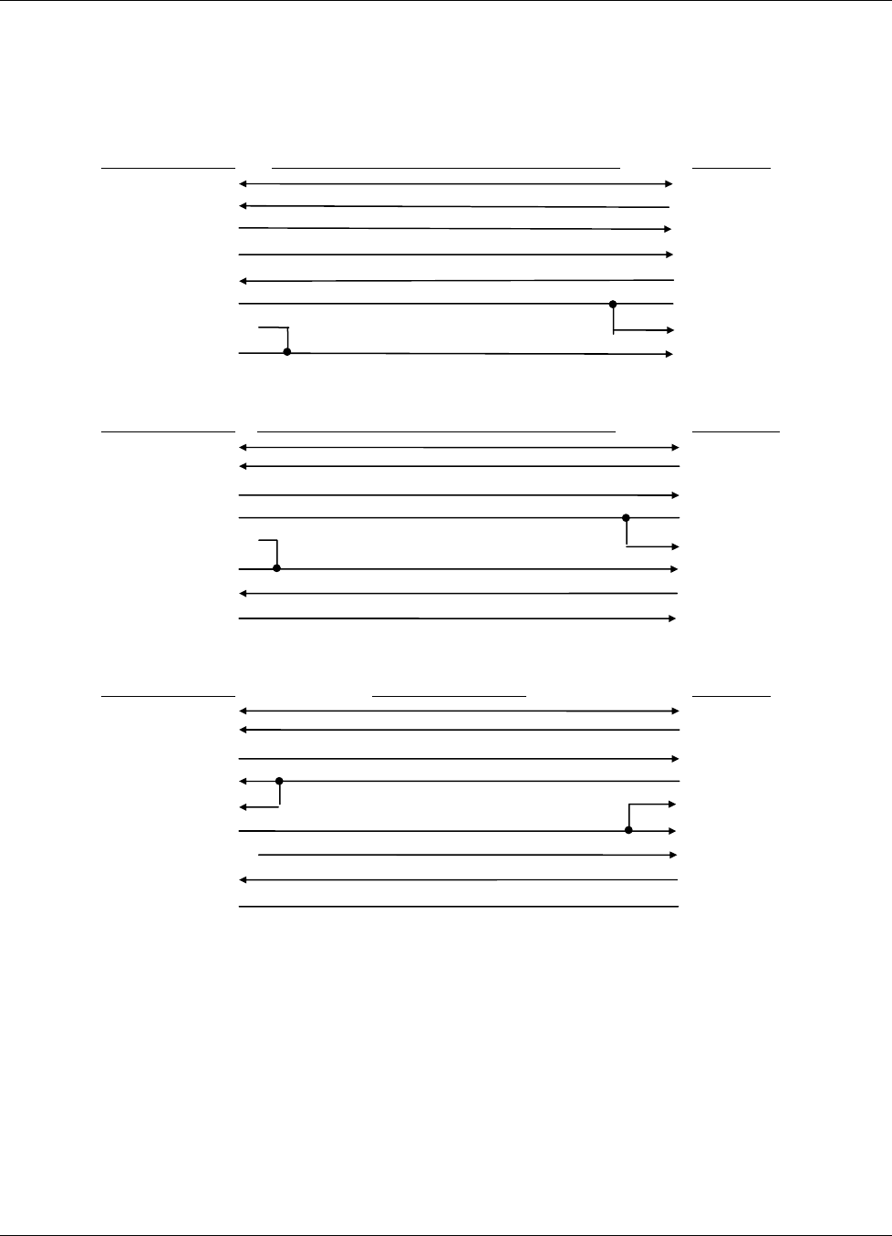
Lake Shore Model 642 Electromagnet Power Supply User’s Manual
7-14 Service
7.10.6 Serial Interface Cable Wiring
The following are suggested cable wiring diagrams for connecting the Model 642 Serial Interface to various Customer
Personal Computers (PCs).
Model 642 to PC Serial Interface – PC with DE-9P
Model 642 DE-9P Standard Null-Modem Cable (DE-9S to DE-9S) PC DE-9P
5 - GND 5 - GND
2 - RD (in) 3 - TD (out)
3 - TD (out) 2 - RD (in)
4 - DTR (out) 6 - DSR (in)
6 - DSR (in) 4 - DTR (out)
1 - NC 7 - RTS (out)
7 - DTR (tied to 4) 8 - CTS (in)
8 - NC 1 - DCD (in)
Model 642 to PC Serial Interface – PC with DB-25P
Model 642 DE-9P Standard Null-Modem Cable (DE-9S to DB-25S) PC DB-25P
5 - GND 7 - GND
2 - RD (in) 2 - TD (out)
3 - TD (out) 3 - RD (in)
1 - NC 4 - RTS (out)
7 - DTR (tied to 4) 5 - CTS (in)
8 - NC 8 - DCD (in)
6 - DSR (in) 20 - DTR (out)
4 - DTR (out) 6 - DSR (in)
Model 642 to PC Interface using Null Modem Adapter
Model 642 DE-9P Null Modem Adapter PC DE-9P
5 - GND 5 - GND
2 - RD (in) 3 - TD (out)
3 - TD (out) 2 - RD (in)
1 – NC (out) 4 - DTR
6 - DSR (in) 1 - DCD (in)
4 - DTR (out) 6 - DSR (in)
7 - DTR (tied to 4) 8 - CTS (in)
8 - NC 7 - RTS (out)
9 - NC 9 - NC
NOTE: Same as null modem cable design except PC CTS is provided from the Model 642 on DTR.
7.10.7 IEEE-488 Parallel Interface Connector
Connect to the IEEE-488 Interface connector on the Model 642 rear with cables specified in the IEEE-488-1978 standard
document. The cable has 24 conductors with an outer shield. The connectors are 24-way Amphenol 57 Series (or
equivalent) with piggyback receptacles to allow daisy-chaining in multiple device systems. The connectors are secured in
the receptacles by two captive locking screws with metric threads. The total length of cable allowed in a system is 2
meters for each device on the bus, or 20 meters maximum. The Model 642 can drive a bus of up to 10 devices. A
connector extender is required to use the IEEE-488 Interface and Relay Terminal Block at the same time. Figure 7-12
shows the IEEE-488 Interface connector pin and signal names as viewed from the Model 642 rear panel.
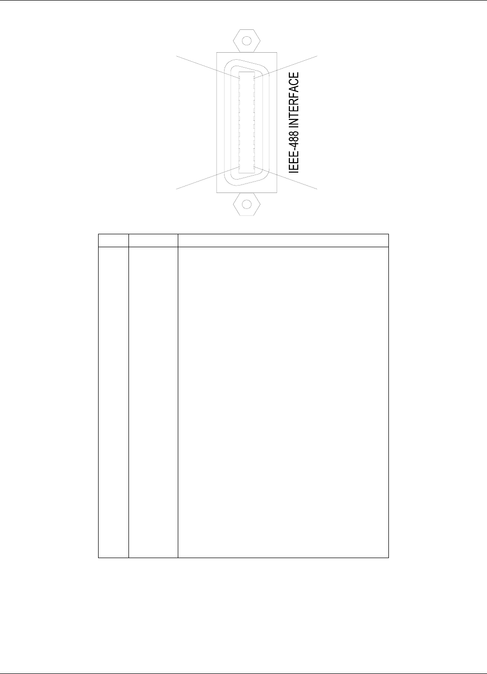
Lake Shore Model 642 Electromagnet Power Supply User’s Manual
Service 7-15
12
1
24
13
Pin Symbol Description
1
2
3
4
5
6
7
8
9
10
11
12
13
14
15
16
17
18
19
20
21
22
23
24
DIO 1
DIO 2
DIO 3
DIO 4
EOI
DAV
NRFD
NDAC
IFC
SRQ
ATN
SHIELD
DIO 5
DIO 6
DIO 7
DIO 8
REN
GND 6
GND 7
GND 8
GND 9
GND 10
GND 11
GND
Data Input/Output Line 1
Data Input/Output Line 2
Data Input/Output Line 3
Data Input/Output Line 4
End Or Identify
Data Valid
Not Ready For Data
Not Data Accepted
Interface Clear
Service Request
Attention
Cable Shield
Data Input/Output Line 5
Data Input/Output Line 6
Data Input/Output Line 7
Data Input/Output Line 8
Remote Enable
Ground Wire – Twisted pair with DAV
Ground Wire – Twisted pair with NRFD
Ground Wire – Twisted pair with NDAC
Ground Wire – Twisted pair with IFC
Ground Wire – Twisted pair with SRQ
Ground Wire – Twisted pair with ATN
Logic Ground
Figure 7-12. IEEE-488 Connector Details

Lake Shore Model 642 Electromagnet Power Supply User’s Manual
7-16 Service
7.11 CALIBRATION
Lake Shore maintains a fully automated calibration fixture for the Model 642 that measures existing performance of the
unit and then recalibrates the using NIST traceable resistance and voltage standards. In addition, non-calibration features
are verified for proper operation by a full battery of extensive tests. Although this testing is very complete, it requires the
return of the Model 642 to Lake Shore to perform the recalibration. In some instances, however, it may be necessary to
recalibrate the Model 642 in the field. Calibration information for the following operating parameters is provided:
• Output Current.
• Output Current Reading
• Output Voltage Reading
• External Programming Voltage Reading
These calibrations are done through the computer interface and the calibration constants are stored in the non-volatile
memory in the instrument. The cover does not have to be removed to calibrate the instrument. The remaining features of
the Model 642 do not require calibration to operate within their specified tolerances.
Uncalibrated (default) values for gains are 1 while offsets are 0. Operation with these values is possible but the accuracy
will be reduced to as much as ±2% of full scale, generally. If the Model 642 is used in closed loop operation and
programmed through the external input, regular calibration may not be required.
7.11.1 Calibration Interface
Computer interface commands are included in the Model 642 specifically for calibration. These commands work with
either the IEEE-488 or RS-232C interface. Refer to Section 7.13.4 for a complete description of each calibration
command.
It is always recommended to read out old calibration coefficients using the CALZ? and CALG? interface queries before
attempting to calibrate. This will give the operator experience with the interface command, data formatting, and typical
values. If the old values are saved, they can be reloaded in the case of accidental loss of data during calibration. New
calculated calibration coefficients should be very similar to the old values. Discrepancy between the old and new values
of more than 0.1% of gain calibration coefficients or 0.1% of range for zero coefficients could indicate an error in the
calibration procedure or a hardware failure. Do not attempt to recalibrate a damaged instrument.
The instrument will use the new calibration coefficients as soon as they are sent with the either the CALZ or CALG
interface command but they are not saved permanently until the CALSAVE command is issued. If a mistake is made in
the calibration process, turn the instrument power off and on again before CALSAVE is issued to restore the old
calibration constants. Once CALSAVE is issued, old values cannot be retrieved from the instrument.
If calibration coefficients are left at default or are outside of the normal calibration range, the following error message
will appear in the instrument display when the instrument is turned on: “Calibration Invalid”. This error message must be
bypassed to allow calibration of the instrument. Press both Enter and Escape keys simultaneously to bypass the error
message. Operation in this state is possible but at least one calibration is known to be out of proper range and
measurement is likely to be erroneous.
Simple communications program examples are shown in Sections 5.1.5.2 and 5.2.7.1. Some time should be spent
becoming familiar with the calibration commands before beginning a calibration. Although the calibration factors are
sent to the Model 642 over the computer interface, this procedure is written to obtain the Model 642 readings solely by
visual observation of the front panel.

Lake Shore Model 642 Electromagnet Power Supply User’s Manual
Service 7-17
7.11.2 Calibration Equipment
1. Calibration Shunt Resistor – The output current of the Model 642 must be measured externally as the primary
reference for calibration. When current is measured, it is the result of the current through the known resistance of the
calibration resistor. This resistor must be accurately measured and its actual value (R Shunt) used to determine the
actual current flow. For example, if the resistor is measured at 0.99661 mΩ, the actual current flowing is calculated
by the following equation.
Ishunt = Vshunt/0.99661 × 10-3 or Ishunt = 1000 × Vshunt/0.99661
This resistor must withstand the full current of the Model 642 and do so with a minimum of heating that can easily
change the resistance and therefore the current measurement. At 70 A, this resistor only dissipates 4.9 W. Even so, it
is highly recommended to mount the resistor on a heat sink with forced air-cooling to minimize temperature rise and
related value changes during calibration. (Alpha PSBWR0010F is suggested)
2. Magnet Load – The Model 642 is designed for a nominal magnet load of 0.5-ohms and 0.5 H. For calibration
purposes, the magnet can easily be used as the calibration load. The calibration shunt resistor is wired in series with
the positive output terminal using a cable of similar current handling capability as the normal magnet lines. An
alternative to this is the use of a resistor bank with total resistance of 0.5-ohms capable of safely dissipating 2,450 W
of heat (the equivalent of a medium sized space heater). This procedure assumes the use of the water-cooled magnet
as a calibration load.
3. DC Voltmeter (DVM) – The voltmeter must measure VDC accurately to 10’s of µV if resolution to 10’s of mA
(from the Model 642). The Agilent Model 34401 DMM or better is suggested.
7.11.3 Calibration Procedure
The following calibration steps should be performed exactly in the order provided. Pay close attention to the use of
“CALZ” vs “CALG” commands. They can easily be confused and will certainly create unexpected results if accidentally
interchanged. Zeroing calibrations use “CALZ” commands while Gain (Span) calibrations use “CALG” commands.
7.11.3.1 Calibrate Current Output Zero
The 1 mΩ shunt resistor is wired in series with the calibration load from the positive output terminals with #4 AWG
wire. Cable length is relatively unimportant but should be less than 5 feet to the shunt resistor. Voltage across the shunt
resistor is to be monitored by the DVM. The DVM input connections must both be isolated from earth (power line)
ground.
1. Send “CALZ 10, 0” to set the output offset constant to 0.
2. Set the Model 642 output current to 0 A.
3. Measure the actual voltage across the shunt and record (Vshunt).
4. Calculate the zero offset constant: -(Vshunt/Rshunt).
5. Send “CALZ 10, zero offset constant”.
6. Reset the Model 642 output current to 0 A (loads the new offset setting).
7. Verify the actual output current to be less than ±1 mA.
8. Send “CALSAVE” to write this calibration to non-volatile memory.
7.11.3.2 Calibrate Current Reading Zero
1. Send “CALZ 0, 0” to set the current reading offset constant to 0.
2. Measure the actual voltage across the shunt and record (Vshunt).
3. Get the Model 642 output current reading (by front panel or interface) and record (I reading).
4. Calculate the zero offset constant: – (Ireading – (Vshunt/Rshunt)).
5. Send “CALZ 0, zero offset constant”.
6. Verify the Model 642 output current reading to match the actual output current within ±0.0005 mA.
7. Send “CALSAVE” to write this calibration to non-volatile memory.

Lake Shore Model 642 Electromagnet Power Supply User’s Manual
7-18 Service
7.13.3.3 Calibrate Output Voltage Reading Zero
This step assumes that the previous two steps are successful and the current through the shunt resistor is quite low
resulting in virtually no voltage across the Model 642 output terminals.
1. Send “CALZ 5, 0” to set the current reading offset constant to 0.
2. Get the Model 642 output voltage reading (by front panel or interface).
3. Calculate zero offset constant: – (output voltage reading).
4. Send “CALZ 5, zero offset constant”.
5. Verify the Model 642 output voltage reading to be 0 ±0.001 V.
6. Send “CALSAVE” to write this calibration to non-volatile memory.
7.11.3.4 Calibrate External Programming Voltage Reading Zero
1. Short the external current programming input lines (pins 3 and 11 of the Analog I/O connector).
2. Send “CALZ 7, 0”. To set the external programming voltage reading constant to 0.
3. Get the Model 642 external programming voltage reading.
NOTE: To get this reading from the Model 642, press and hold the Status key on the front panel until the display
goes dark (≈3 seconds). When the key is then released, a diagnostics display will be seen. The upper right
reading, “EXT PROG”, is the reading needed for this step.
4. Calculate zero offset constant: – (external programming voltage reading).
5. Send “CALZ 7, zero offset constant”.
6. Verify the Model 642 external programming voltage reading to be 0 ±0.0001 V.
7. Send “CALSAVE” to write this calibration to non-volatile memory.
7.11.3.5 Calibrate Output Current Gain (Span)
This calibration is the most difficult and most important of the procedure. It first requires measuring the span of the trim
range (which changes from unit to unit within 1 – 2%) to determine the trim adjustment range that corresponds to a
100% calibration trim change. In other words, we adjust the calibration in % from –100% to +100% but the size of the
calibration trim range changes slightly for each unit. We first measure the span of the calibration trim range and then
measure the full span of the instrument with the calibration trim set to 0%. We have adopted the use of % as the unit
name for the trim calibration since it corresponds to only the percent of trim range and not the full span of the
instrument.
The 65 A set point for calibration is chosen because the maximum trim range at 70 A forces the current past the 70.1 A
internal analog limit and therefore creates significant error. The shunt resistor remains connected in series with the
magnet load for this procedure.
1. Send “CALG 10, 0”. To set the output current gain trim constant to 0.
2. Set the Model 642 output current to +65 A (ramp rate 30 A/s nominal).
3. Wait 30 seconds for settling.
4. Measure the actual voltage across the shunt and record (Vshunt).
5. Calculate and record (Imax): Vshunt/Rshunt.
6. Send “CALG 10, –100”. To set the output current gain trim constant to maximum.
7. Wait 10 seconds.
8. Measure the actual voltage across the shunt and record (Vshunt).
9. Calculate and record (Imaxpostrim): Vshunt/Rshunt.
10. Send “CALG 10, +100”. To set the output current gain trim constant to minimum.
11. Wait 10 seconds.

Lake Shore Model 642 Electromagnet Power Supply User’s Manual
Service 7-19
Calibrate Output Current Gain (Continued)
12. Measure the actual voltage across the shunt and record (Vshunt).
13. Calculate and record (Iminpostrim): Vshunt/Rshunt.
14. Send “CALG 10, 0”. To set the output current gain trim constant to 0.
15. Set the Model 642 to –65A V (ramp rate 30 A/s nominal).
16. Wait 30 seconds for settling.
17. Measure the actual voltage across the shunt and record (Vshunt).
18. Calculate and record (Imin): Vshunt/Rshunt.
19. Send “CALG 10, –100”. To set the output current gain trim constant to maximum.
20. Wait 10 Seconds.
21. Measure the actual voltage across the shunt and record (Vshunt).
22. Calculate and record (Imaxnegtrim): Vshunt/Rshunt.
23. Send “CALG 10, +100”. To set the output current gain trim constant to minimum.
24. Wait 10 seconds.
25. Measure the actual voltage across the shunt and record (Vshunt).
26. Calculate and record (Iminnegtrim): Vshunt/Rshunt.
27. Send “CALG 10, 0”. To return the output current gain trim constant to 0.
28. Set the Model 642 output current to 0 A.
29. Calculate the gain constant per the following equation:
Current Output Gain Constant = 200((Imax-Imin) – 130)/((Imaxpostrim-Iminpostrim) – (Imaxnegtrim-Iminnegtrim))
30. Send “CALG 10, gain constant”.
This method, while somewhat lengthy, averages the trim spans between negative and positive settings to split the error
between positive and negative operation.
This gain calibration may shift the initial zero calibration for the Current Output DAC slightly. It is best to repeat the
current zero calibrations at this point.
31. Recalibrate Current Output Zero (refer to Section 7.13.3.1).
32. Recalibrate Current Reading Zero (refer to Section 7.13.3.2).
33. Set the Model 642 output current to 65 A (ramp rate 30 A/s nominal).
34. Wait 30 seconds.
35. Measure the actual voltage across the shunt and record (Vshunt).
36. Calculate and record (Iout+): Vshunt/Rshunt.
37. Verify Iout = 65 A ±0.010 A (0.015%).
39. Set the Model 642 output current to –65 A (ramp rate 30 A/s nominal).
40. Wait 30 seconds.
41. Calculate and record (Iout–): Vshunt/Rshunt.
42. Verify Iout = –65 A ±0.010 A (0.015%).
43. Set the Model 642 output current to 0 A.
44. Send “CALSAVE” to write this calibration to non-volatile memory.

Lake Shore Model 642 Electromagnet Power Supply User’s Manual
7-20 Service
7.13.3.6 Calibrate Current Reading Gain
1. Send “CALG 0, 1”. To set the output current reading gain constant to 1.
2. Set the Model 642 output current to –70 A. (Ramp rate 30 A/s nominal).
3. Wait 30 seconds.
4. Measure the actual voltage across the shunt and record (Vshunt).
5. Calculate and record (Imeasuredneg): Vshunt/Rshunt.
6. Get the Model 642 output current reading (by front panel or interface) and record (Ireadingneg).
7. Set the Model 642 output current to +70 A (Ramp rate 30 A/s nominal).
8. Wait 30 seconds.
9. Measure the actual voltage across the shunt and record (Vshunt).
10. Calculate and record (Imeasuredpos): Vshunt/Rshunt.
11. Get the Model 642 output current reading (by front panel or interface) and record (Ireadingpos).
12. Calculate gain constant per the following equation:
Current Reading Gain Constant = (Imeasuredpos – Imeasuredneg)/(Ireadingpos – Ireadingneg)
13. Verify gain factor to be 1, ±0.02.
14. Send “CALG 0, gain constant”.
15. Verify the Model 642 output current reading to equal Imeasuredpos, ±0.010 A.
16. Set the Model 642 output current to 0 A.
17. Send “CALSAVE” to write this calibration to non-volatile memory.
This method is somewhat lengthy, but averages the differences between positive (+) and negative (–) excursions.
7.11.3.7 Calibrate Voltage Reading Gain
1. Send “CALG 5, 1”. To set the output voltage reading gain constant to 1.
2. Set the Model 642 output current to 65 A.
3. Wait 30 seconds.
4. Measure the Model 642 actual output voltage at the output terminals and record (Vmeasuredpos).
5. Get the Model 642 output voltage reading (by front panel or interface) and record (Vreadingpos).
6. Set the Model 642 output current to –65 A.
7. Wait 30 seconds.
8. Measure the Model 642 actual output voltage at the output terminals and record (Vmeasuredneg).
9. Get the Model 642 output voltage reading (by front panel or interface) and record (Vreadingneg).
10. Calculate gain constant per the following equation:
Voltage Reading Gain Constant = (Vmeasuredpos -Vmeasuredneg)/(Vreadingpos -Vreadingneg)
11. Verify the gain factor to be 1, ±0.02.
12. Send “CALG 5, gain constant”.
13. Verify the Model 642 output voltage reading to match the actual output voltage within, ±0.001 V.
14. Set the Model 642 output current to 0 A.
15. Send “CALSAVE” to write this calibration to non-volatile memory.

Lake Shore Model 642 Electromagnet Power Supply User’s Manual
Service 7-21
7.11.3.8 Calibrate External Current Programming Voltage Reading Gain
This procedure calibrates only the input voltage reading of the External Programming Input. The actual current output
from this input is specified to a 1% tolerance and is not adjustable. It is NOT necessary to engage the External
Programming feature of the Model 642 for this calibration.
1. Connect a new 9 V alkaline battery to the external current programming input lines (positive to positive input).
2. Send “CALG 7, 1”. To set the external programming voltage reading gain constant to 1.
3. Get the Model 642 external programming voltage reading and record (Vreading).
NOTE: To get this reading from the Model 642, press and hold the Status key on the front panel until the display
goes dark (~3 seconds). When the key is then released, a diagnostics display will be seen. The upper right
reading, “Ext Prog”, is the reading needed for this step.
4. Measure the voltage directly across the 9 V battery and record (Vmeasured)
5. Calculate the gain constant per the following equation:
Programming Voltage Reading Gain Constant = Vmeasured/Vreading
6. Verify the gain constant to be 1, ±0.05.
7. Send “CALG 7, constant”.
8. Verify the Model 642 external programming voltage reading to match the measured 9 V battery voltage within,
±0.0005 V.
9. Send “CALSAVE” to write this calibration to non-volatile memory.
7.11.4 Calibration-Specific Interface Commands
The following interface commands are only used during calibration and are in addition to those listed in Chapter 5.
CALG Gain Calibration Constant Command
Input: CALG <type>, <value>[term]
Format: nn, ±nnnnnnn
<input> Specifies the item to calibrate. Valid entries are:
0 = Output I Reading
1 = Bias A Reading *
2 = Bias B Reading *
3 = Gnd Diff Reading *
4 = Out Con Reading *
5 = Output V Reading
6 = Boost V Reading*
7 = Ext Prog Input Reading
8 = Temp Reading*
9 = Out Stg V Reading *
10 = Actual Output Current
<value> Gain calibration constant value.
Remarks: Items marked with a * are for internal diagnostic use only and should always be set
to a value of 1 (default).

Lake Shore Model 642 Electromagnet Power Supply User’s Manual
7-22 Service
CALG? Gain Calibration Constant Query
Input: CALG? <type>[term]
Format: nn
<type> 0 – 10.
Returned: <value>[term]
Format: ±nnnnnnn (Refer to command for description)
CALSAVE Calibration Save Command
Input: CALSAVE[term]
Remarks: Saves all CALZ and CALG calibration constants in non-volatile memory.
CALZ Zero Offset Calibration Constant Command
Input: CALZ <type>, <value>[term]
Format: nn, ±nnnnnnn
<type> Specifies the item to calibrate. Valid entries are:
0 = Output I Reading
1 = Bias A Reading *
2 = Bias B Reading *
3 = Gnd Diff Reading *
4 = Out Con Reading *
5 = Output V Reading
6 = Boost V Reading*
7 = Ext Prog Input Reading
8 = Temp Reading*
9 = Out Stg V Reading *
10 = Actual Output Current
<value> Zero offset calibration constant value.
Remarks: Items marked with a * are for internal diagnostic use only and should always be set
to a value of 0 (default).
CALZ? Zero Offset Calibration Constant Query
Input: CALZ? <type>[term]
Format: nn
<type> 0 – 10.
Returned: <value>[term]
Format: ±nnnnnnn (Refer to command for description)
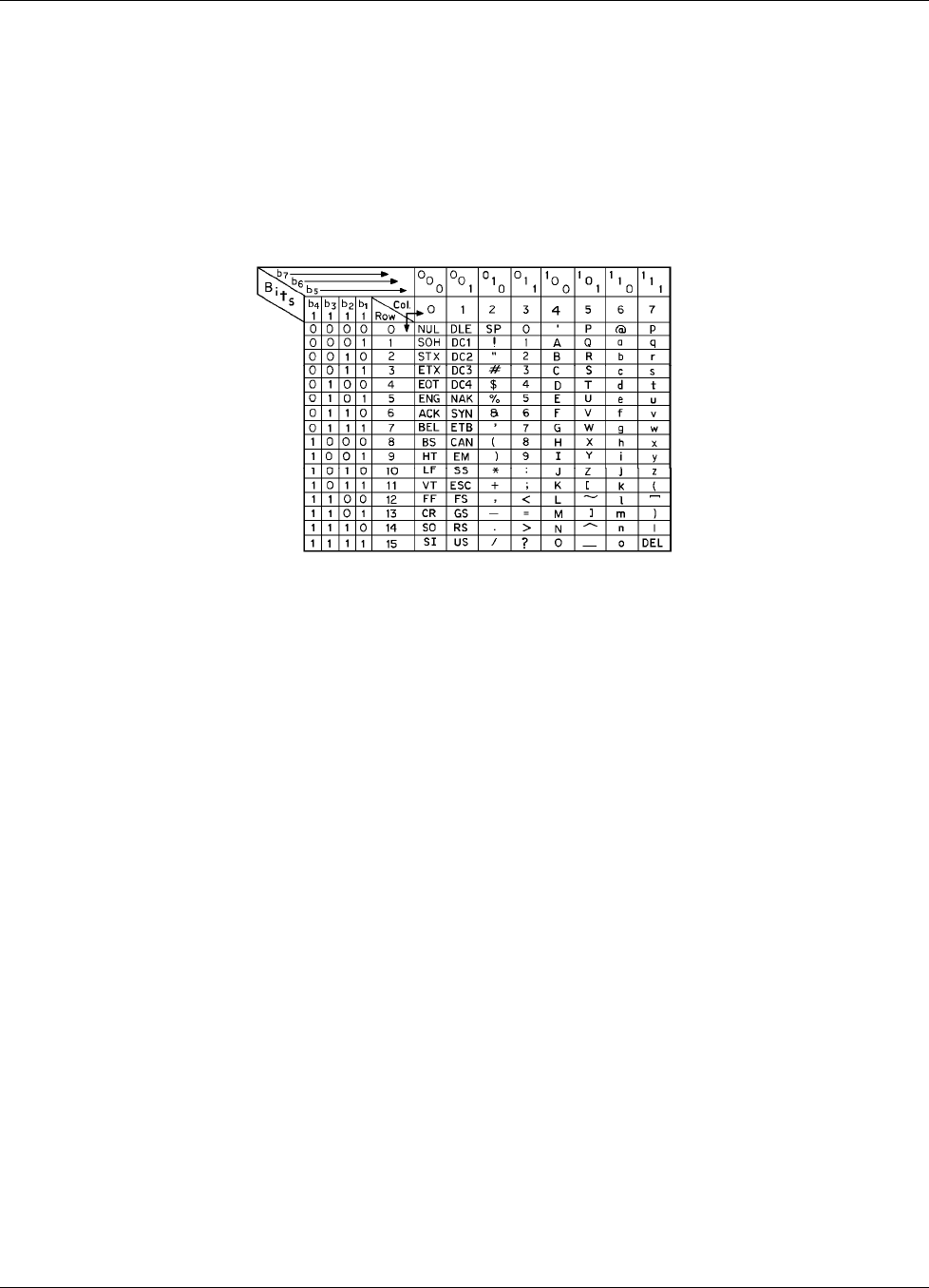
Lake Shore Model 642 Electromagnet Power Supply User’s Manual
Glossary of Terminology A-1
APPENDIX A
GLOSSARY OF TERMINOLOGY
accuracy. The degree of correctness with which a measured value agrees with the true value.2
electronic accuracy. The accuracy of an instrument independent of the sensor.
sensor accuracy. The accuracy of a temperature sensor and its associated calibration or its ability to match a standard curve.
American Standard Code for Information Interchange (ASCII). A standard code used in data transmission, in which
128 numerals, letters, symbols, and special control codes are represented by a 7-bit binary number as follows:
American Wire Gage (AWG). Wiring sizes are defined as diameters in inches and millimeters as follows:
AWG Dia. In. Dia. mm AWG Dia. In. Dia. mm AWG Dia. In. Dia. mm AWG Dia. In. Dia. mm
1 0.2893 7.348 11 0.0907 2.304 21 0.0285 0.7230 31 0.0089 0.2268
2 0.2576 6.544 12 0.0808 2.053 22 0.0253 0.6438 32 0.0080 0.2019
3 0.2294 5.827 13 0.0720 1.829 23 0.0226 0.5733 33 0.00708 0.178
4 0.2043 5.189 14 0.0641 1.628 24 0.0207 0.5106 34 0.00630 0.152
5 0.1819 4.621 15 0.0571 1.450 25 0.0179 0.4547 35 0.00561 0.138
6 0.1620 4.115 16 0.0508 1.291 26 0.0159 0.4049 36 0.00500 0.127
7 0.1443 3.665 17 0.0453 1.150 27 0.0142 0.3606 37 0.00445 0.1131
8 0.1285 3.264 18 0.0403 1.024 28 0.0126 0.3211 38 0.00397 0.1007
9 0.1144 2.906 19 0.0359 0.9116 29 0.0113 0.2859 39 0.00353 0.08969
10 0.1019 2.588 20 0.0338 0.8118 30 0.0100 0.2546 40 0.00314 0.07987
ambient temperature. The temperature of the surrounding medium, such as gas or liquid, which comes into contact with the
apparatus.1
ampere. The constant current that, if maintained in two straight parallel conductors of infinite length, of negligible circular cross
section, and placed one meter apart in a vacuum, would produce between these conductors a force equal to 2 × 10⁻⁷ newton per
meter of length.2 This is one of the base units of the SI.
ampere-turn. A MKS unit of magnetomotive force equal to the magnetomotive force around a path linking one turn of a conducting
loop carrying a current of one ampere; or 1.26 gilberts.
ampere/meter (A/m). The SI unit for magnetic field strength (H). 1 ampere/meter = 4π/1000 oersted ≈0.01257 oersted.
analog controller. A feedback control system where there is an unbroken path of analog processing between the feedback device
(sensor) and control actuator (heater).
analog data. Data represented in a continuous form, as contrasted with digital data having discrete values.1
analog output. A voltage output from an instrument that is proportional to its input. For example, from a digital voltmeter, the output
voltage is generated by a digital-to-analog converter so it has a discrete number of voltage levels.
autotuning. In Lake Shore instruments, the Autotuning algorithm automatically determines the proper settings for Gain
(Proportional), Reset (Integral), and Rate (Derivative) by observing the time response of the system upon changes in setpoint.
B. Symbol for magnetic flux density. See Magnetic Flux Density.
bar. Unit of pressure equal to 105 pascal, or 0.98697 standard atmosphere.
Baud. A unit of signaling speed equal to the number of discrete conditions or signal events per second, or the reciprocal of the time of
the shortest signal element in a character.2
bit. A contraction of the term “binary digit”; a unit of information represented by either a zero or a one.2
BNC. Bayonet Nut Connector.

Lake Shore Model 642 Electromagnet Power Supply User’s Manual
A-2 Glossary of Terminology
boiling point. The temperature at which a substance in the liquid phase transforms to the gaseous phase; commonly refers to the
boiling point at sea level and standard atmospheric pressure.
calibrate. To determine, by measurement or comparison with a standard, the correct value of each scale reading on a meter or other
device, or the correct value for each setting of a control knob.1
Carbon-Glass™. A temperature sensing material fabricated from a carbon-impregnated glass matrix used to make the Lake Shore
Carbon Glass Resistor (CGR) family of sensors.
Celsius (°C) Scale. A temperature scale that registers the freezing point of water as 0 °C and the boiling point as 100 °C under normal
atmospheric pressure. Celsius degrees are purely derived units, calculated from the Kelvin Thermodynamic Scale. Formerly known
as “centigrade.” See Temperature for conversions.
Cernox™. A Lake Shore resistance temperature detector based on a ceramic-oxy-nitride resistance material.
cgs system of units. A system in which the basic units are the centimeter, gram, and second.2
Chebychev polynomials. A family of orthogonal polynomials which solve Chebychev’s differential equation.1
Chebychev differential equation. A special case of Gauss' hypergeometric second-order differential equation:
(1 – x2) f" (x) – xf' (x) + n2f (x) = 0.1
closed-loop. See feedback control system.
coercive force (coercive field). The magnetic field strength (H) required to reduce the magnetic induction (B) in a magnetic material
to zero.
coercivity. generally used to designate the magnetic field strength (H) required to reduce the magnetic induction (B) in a magnetic
material to zero from saturation. The coercivity would be the upper limit to the coercive force.
cryotronics. The branch of electronics that deals with the design, construction, and use of cryogenic devices.1
Curie temperature (Tc). Temperature at which a magnetized sample is completely demagnetized due to thermal agitation. Named for
Pierre Curie (1859 – 1906), a French chemist.
current source. A type of power supply that supplies a constant current through a variable load resistance by automatically varying its
compliance voltage. A single specification given as “compliance voltage” means the output current is within specification when the
compliance voltage is between zero and the specified voltage.
curve. A set of data that defines the temperature response of a temperature sensor. It is used to convert the signal from the sensor to
temperature.
demagnetization. when a sample is exposed to an applied field (Ha), poles are induced on the surface of the sample. Some of the
returned flux from these poles is inside of the sample. This returned flux tends to decrease the net magnetic field strength internal to
the sample yielding a true internal field (Hint) given by: Hint = Ha – DM ,where M is the volume magnetization and D is the
demagnetization factor. D is dependent on the sample geometry and orientation with respect to the field.
deviation. The difference between the actual value of a controlled variable and the desired value corresponding to the setpoint.1
differential permeability. The slope of a B versus H curve: µd = dB/dH.
differential susceptibility. The slope of a M versus H curve: χd = dM/dH.
digital controller. A feedback control system where the feedback device (sensor) and control actuator (heater) are joined by a digital
processor. In Lake Shore controllers the heater output is maintained as a variable DC current source.
digital data. Pertaining to data in the form of digits or interval quantities. Contrast with analog data.2
dimensionless sensitivity. Sensitivity of a physical quantity to a stimulus, expressed in dimensionless terms. The dimensionless
temperature sensitivity of a resistance temperature sensor is expressed as Sd = (T/R)(dR/dT) which is also equal to the slope of R
versus T on a log-log plot, that is Sd = d lnR/d lnT. Note that the absolute temperature (in Kelvin) must be used in these expressions.
drift, instrument. An undesired but relatively slow change in output over a period of time, with a fixed reference input. Note: Drift is
usually expressed in percent of the maximum rated value of the variable being measured.2
electromagnet. A device in which a magnetic field is generated as the result of electrical current passing through a helical conducting
coil. It can be configured as an iron-free solenoid in which the field is produced along the axis of the coil, or an iron-cored structure
in which the field is produced in an air gap between pole faces. The coil can be water cooled copper or aluminum, or
superconductive.
electrostatic discharge (ESD). A transfer of electrostatic charge between bodies at different electrostatic potentials caused by direct
contact or induced by an electrostatic field.
error. Any discrepancy between a computed, observed, or measured quantity and the true, specified, or theoretically correct value or
condition.2
excitation. Either an AC or DC input to a sensor used to produce an output signal. Common excitations include: constant current,
constant voltage, or constant power.
Fahrenheit (°F) Scale. A temperature scale that registers the freezing point of water as 32 °F and the boiling point as 212 °F under
normal atmospheric pressure. See Temperature for conversions.
feedback control system. A system in which the value of some output quantity is controlled by feeding back the value of the
controlled quantity and using it to manipulate an input quantity so as to bring the value of the controlled quantity closer to a desired
value. Also known as closed-loop control system.1

Lake Shore Model 642 Electromagnet Power Supply User’s Manual
Glossary of Terminology A-3
four-lead. measurement technique where one pair of excitation leads and an independent pair of measurement leads are used to
measure a sensor. This method reduces the effect of lead resistance on the measurement.
gamma. A cgs unit of low-level flux density, where 100,000 gamma equals one oersted, or 1 gamma equals 10–5 oersted.
gauss (G). The cgs unit for magnetic flux density (B). 1 gauss = 10–4 tesla. Named for Karl Fredrich Gauss (1777 – 1855) a German
mathematician, astronomer, and physicist.
gaussian system (units). A system in which centimeter-gram-second units are used for electric and magnetic qualities.
general purpose interface bus (GPIB). Another term for the IEEE-488 bus.
germanium (Ge). A common temperature sensing material fabricated from doped germanium to make the Lake Shore GR family of
resistance temperature sensor elements.
gilbert (Gb). A cgs electromagnetic unit of the magnetomotive force required to produce one maxwell of magnetic flux in a magnetic
circuit of unit reluctance. One gilbert is equal to 10/4π ampere-turn. Named for William Gilbert
(1540 – 1603), an English physicist; hypothesized that the Earth is a magnet.
gilbert per centimeter. Practical cgs unit of magnet intensity. Gilberts per cm are the same as oersteds.
Greek alphabet. The Greek alphabet is defined as follows:
Alpha α Α Iota ι Ι Rho ρ Ρ
Beta β Β Kappa κ Κ Sigma σ Σ
Gamma γ Γ Lambda λ Λ Tau τ Τ
Delta δ Δ Mu μ Μ Upsilon υ Υ
Epsilon ε Ε Nu ν Ν Phi φ Φ
Zeta ζ Ζ Xi ξ Ξ Chi χ Χ
Eta η Η Omicron ο Ο Psi ψ Ψ
Theta θ Θ Pi π Π Omega ω Ω
ground. A conducting connection, whether intentional or accidental, by which an electric circuit or equipment is connected to the
Earth, or to some conducting body of relatively large extent that serves in place of the Earth.
Note: It is used for establishing and maintaining the potential of the Earth (or of the conducting body) or approximately that
potential, on conductors connected to it, and for conducting ground current to and from the Earth (or of the conducting body).2
H. Symbol for magnetic field strength. See Magnetic Field Strength.
Hall effect. The generation of an electric potential perpendicular to both an electric current flowing along a thin conducting material
and an external magnetic field applied at right angles to the current. Named for Edwin H. Hall (1855 – 1938), an American physicist.
hertz (Hz). A unit of frequency equal to one cycle per second.
hysteresis. The dependence of the state of a system on its previous history, generally in the form of a lagging of a physical effect
behind its cause.1 Also see magnetic hysteresis.
IEC. International Electrotechnical Commission.
IEEE. Institute of Electrical and Electronics Engineers.
IEEE-488. An instrumentation bus with hardware and programming standards designed to simplify instrument interfacing. The
addressable, parallel bus specification is defined by the IEEE.
initial permeability. The permeability determined at H = 0 and B = 0.
initial susceptibility. The susceptibility determined at H = 0 and M = 0.
infrared (IR). For practical purposes any radiant energy within the wavelength range 770 to 106 nanometers is considered infrared
energy.2 The full range is usually divided into three sub-ranges: near IR, far IR, and sub-millimeter.
interchangeability. Ability to exchange one sensor or device with another of the same type without a significant change in output or
response.
international system of units (SI). A universal coherent system of units in which the following seven units are considered basic:
meter, kilogram, second, ampere, Kelvin, mole, and candela. The International System of Units, or Système International d'Unités
(SI), was promulgated in 1960 by the Eleventh General Conference on Weights and Measures. For definition, spelling, and
protocols, see Reference 3 for a short, convenient guide.
interpolation table. A table listing the output and sensitivity of a sensor at regular or defined points which may be different from the
points at which calibration data was taken.
intrinsic coercivity. The magnetic field strength (H) required to reduce the magnetization (M) or intrinsic induction in a magnetic
material to zero.
intrinsic induction. The contribution of the magnetic material (Bi) to the total magnetic induction (B).
Bi = B – µ0H (SI) Bi = B – H (cgs)
isolated (neutral system). A system that has no intentional connection to ground except through indicating, measuring, or protective
devices of very-high impedance.2
Kelvin (K). The unit of temperature on the Kelvin Scale. It is one of the base units of SI. The word “degree” and its symbol (°) are
omitted from this unit. See Temperature Scale for conversions.

Lake Shore Model 642 Electromagnet Power Supply User’s Manual
A-4 Glossary of Terminology
Kelvin Scale. The Kelvin Thermodynamic Temperature Scale is the basis for all international scales, including the
ITS-90. It is fixed at two points: the absolute zero of temperature (0 K), and the triple point of water (273.16 K), the equilibrium
temperature that pure water reaches in the presence of ice and its own vapor.
line regulation. The maximum steady-state amount that the output voltage or current changes as result of a specified change in input
line voltage (usually for a step change between 105 – 125 or 210 – 250 volts, unless otherwise specified).
line voltage. The RMS voltage of the primary power source to an instrument.
load regulation. A steady-state decrease of the value of the specified variable resulting from a specified increase in load, generally
from no-load to full-load unless otherwise specified.
lock-in amplifier. An amplifier that uses some form of automatic synchronization with an external reference signal to detect and
measure very weak electromagnetic radiation at radio or optical wavelengths in the presence of very high noise levels.1
M. Symbol for magnetization. See magnetization.
magnetic air gap. The air space, or non-magnetic portion, of a magnetic circuit.
magnetic field strength (H). The magnetizing force generated by currents and magnetic poles. For most applications, the magnetic
field strength can be thought of as the applied field generated, for example, by a Electromagnet. The magnetic field strength is not a
property of materials. Measure in SI units of A/m or cgs units of oersted.
magnetic flux density (B). Also referred to as magnetic induction. This is the net magnetic response of a medium to an applied field,
H. The relationship is given by the following equation: B = µ0(H + M) for SI, and B = H + 4πM for cgs, where H = magnetic field
strength, M = magnetization, and µ0 = permeability of free space = 4π × 10–7 H/m.
magnetic hysteresis. The property of a magnetic material where the magnetic induction (B) for a given magnetic field strength (H)
depends upon the past history of the samples magnetization.
magnetic induction (B). See magnetic flux density.
magnetic moment (m). This is the fundamental magnetic property measured with dc magnetic measurements systems such as a
vibrating sample magnetometer, extraction magnetometer, SQUID magnetometer, etc. The exact technical definition relates to the
torque exerted on a magnetized sample when placed in a magnetic field. Note that the moment is a total attribute of a sample and
alone does not necessarily supply sufficient information in understanding material properties. A small highly magnetic sample can
have exactly the same moment as a larger weakly magnetic sample (see Magnetization). Measured in SI units as A·m2 and in cgs
units as emu. 1 emu = 10–3 A·m2.
magnetic units. Units used in measuring magnetic quantities. Includes ampere-turn, gauss, gilbert, line of force, maxwell, oersted,
and unit magnetic pole.
magnetization (M). This is a material specific property defined as the magnetic moment (m) per unit volume (V). M = m/V.
Measured in SI units as A/m and in cgs units as emu/cm3. 1 emu/cm3 = 103 A/m. Since the mass of a sample is generally much
easier to determine than the volume, magnetization is often alternately expressed as a mass magnetization defined as the moment
per unit mass.
microcontroller. A microcomputer, microprocessor, or other equipment used for precise process control in data handling,
communication, and manufacturing.1
MKSA System of Units. A system in which the basic units are the meter, kilogram, and second, and the ampere is a derived unit
defined by assigning the magnitude 4π × 10–7 to the rationalized magnetic constant (sometimes called the permeability of space).
negative temperature coefficient (NTC). Refers to the sign of the temperature sensitivity. For example, the resistance of a NTC
sensor decreases with increasing temperature.
National Institute of Standards and Technology (NIST). Government agency located in Gaithersburg, Maryland and Boulder,
Colorado, that defines measurement standards in the United States.
noise (electrical). Unwanted electrical signals that produce undesirable effects in circuits of control systems in which they occur.2
normalized sensitivity. For resistors, signal sensitivity (dR/dT) is geometry dependent; i.e., dR/dT scales directly with R;
consequently, very often this sensitivity is normalized by dividing by the measured resistance to give a sensitivity, sT, in percent
change per Kelvin. sT = (100/R) (dR/dT) %K, where T is the temp. in Kelvin and R is the resistance in ohms.
normally closed (N.C.). A term used for switches and relay contacts. Provides a closed circuit when actuator is in the free
(unenergized) position.
normally open (N.O.). A term used for switches and relay contacts. Provides an open circuit when actuator is in the free
(unenergized) position.
oersted (Oe). The cgs unit for the magnetic field strength (H). 1 oersted = 10¾π ampere/meter ≈79.58 ampere/meter.
ohm (Ω). The SI unit of resistance (and of impedance). The ohm is the resistance of a conductor such that a constant current of one
ampere in it produces a voltage of one volt between its ends.2
open-loop. A control system in which the system outputs are controlled by system inputs only, and no account is taken of actual
system output.1
pascal (Pa). The SI unit of pressure equal to 1 N/m2. Equal to 1.45 × 10⁻⁴ psi, 1.0197 × 10⁻⁵ kgf /cm2, 7.5 × 10⁻³ torr,
4.191 × 10⁻³ inches of water, or 1 × 10⁻⁵ bar.

Lake Shore Model 642 Electromagnet Power Supply User’s Manual
Glossary of Terminology A-5
permeability. Material parameter which is the ratio of the magnetic induction (B) to the magnetic field strength (H):
µ = B/H. Also see Initial Permeability and Differential Permeability.
platinum (Pt). A common temperature sensing material fabricated from pure platinum to make the Lake Shore PT family of
resistance temperature sensor elements.
polynomial fit. A mathematical equation used to fit calibration data. Polynomials are constructed of finite sums of terms of the form
aixi , where ai is the ith fit coefficient and xi is some function of the dependent variable.
positive temperature coefficient (PTC). Refers to the sign of the temperature sensitivity. For example, the resistance of a PTC sensor
increases with increasing temperature.
pounds per square inch (psi). A unit of pressure. 1 psi = 6.89473 kPa. Variations include psi absolute (psia) measured relative to
vacuum (zero pressure) where one atmosphere pressure equals 14.696 psia and psi gauge (psig) where gauge measured relative to
atmospheric or some other reference pressure.
ppm. Parts per million, e.g., 4 × 10⁻⁶ is four parts per million.
precision. Careful measurement under controlled conditions which can be repeated with similar results. See repeatability. Also means
that small differences can be detected and measured with confidence. See resolution.
prefixes. SI prefixes used throughout this manual are as follows:
Factor Prefix Symbol
1024 yotta Y
1021 zetta Z
1018 exa E
1015 peta P
1012 tera T
109 giga G
106 mega M
103 kilo k
102 hecto h
101 deka da
Factor Prefix Symbol
10–1 deci d
10–2 centi c
10–3 milli m
10–6 micro µ
10–9 nano n
10–12 pico p
10–15 femto f
10–18 atto a
10–21 zepto z
10–24 yocto y
probe. A long, thin body containing a sensing element which can be inserted into a system in order to make measurements. Typically,
the measurement is localized to the region near the tip of the probe.
proportional, integral, derivative (PID). A control function where output is related to the error signal in three ways. Proportional
(gain) acts on the instantaneous error as a multiplier. Integral (reset) acts on the area of error with respect to time and can eliminate
control offset or droop. Derivative (rate) acts on the rate of change in error to dampen the system, reducing overshoot.
rack mount. An instrument is rack mountable when it has permanent or detachable brackets that allow it to be securely mounted in an
instrument rack. The standard rack-mount is 19 inches wide. A full-rack instrument requires the entire width of the rack. Two half-
rack instruments fit horizontally in one rack width.
relief valve. A type of pressure relief device which is designed to relieve excessive pressure, and to reclose and reseal to prevent
further flow of gas from the cylinder after reseating pressure has been achieved.
remanence. The remaining magnetic induction in a magnetic material when the material is first saturated and then the applied field is
reduced to zero. The remanence would be the upper limit to values for the remanent induction. Note that no strict convention exists
for the use of remanent induction and remanence and in some contexts the two terms may be used interchangeably.
remanent induction. The remaining magnetic induction in a magnetic material after an applied field is reduced to zero. Also see
remanence.
repeatability. The closeness of agreement among repeated measurements of the same variable under the same conditions.2
resistance temperature detector (RTD). Resistive sensors whose electrical resistance is a known function of the temperature, made
of, e.g., carbon-glass, germanium, platinum, or rhodium-iron.
resolution. The degree to which nearly equal values of a quantity can be discriminated.2
display resolution. The resolution of the physical display of an instrument. This is not always the same as the measurement
resolution of the instrument. Decimal display resolution specified as "n digits" has 10n possible display values. A resolution of n
and one-half digits has 2 × 10n possible values.
measurement resolution. The ability of an instrument to resolve a measured quantity. For digital instrumentation this is often
defined by the analog to digital converter being used. A n-bit converter can resolve one part in 2n. The smallest signal change that
can be measured is the full scale input divided by 2n for any given range. Resolution should not be confused with accuracy.
RhFe. Rhodium-iron. Rhodium alloyed with less than one atomic percent iron is used to make the Lake Shore RF family of sensors.
Rhodium-iron is a spin fluctuation alloy which has a significant temperature coefficient of resistance below 20 K where most metals
rapidly lose sensitivity.
root mean square (RMS). The square root of the time average of the square of a quantity; for a periodic quantity the average is taken
over one complete cycle. Also known as effective value.1
RS-232C. Bi-directional computer serial interface standard defined by the Electronic Industries Association (EIA). The interface is
single-ended and non-addressable.
Lake Shore Model 642 Electromagnet Power Supply User’s Manual
A-6 Glossary of Terminology
Seebeck effect. The development of a voltage due to differences in temperature between two junctions of dissimilar metals in the
same circuit.1
self-heating. Heating of a device due to dissipation of power resulting from the excitation applied to the device. The output signal
from a sensor increases with excitation level, but so does the self-heating and the associated temperature measurement error.
sensitivity. The ratio of the response or change induced in the output to a stimulus or change in the input. Temperature sensitivity of a
resistance temperature detector is expressed as S = dR/dT.
setpoint. The value selected to be maintained by an automatic controller.1
serial interface. A computer interface where information is transferred one bit at a time rather than one byte (character) at a time as in
a parallel interface. RS-232C is the most common serial interface.
SI. Système International d'Unités. See International System of Units.
stability. The ability of an instrument or sensor to maintain a constant output given a constant input.
strain relief. A predetermined amount of slack to relieve tension in component or lead wires. Also called stress relief.
susceptance. In electrical terms, susceptance is defined as the reciprocal of reactance and the imaginary part of the complex
representation of admittance: [suscept(ibility) + (conduct)ance].
susceptibility (χ). Parameter giving an indication of the response of a material to an applied magnetic field. The susceptibility is the
ratio of the magnetization (M) to the applied field (H). χ = M/H. In both SI units and cgs units the volume susceptibility is a
dimensionless parameter. Multiply the cgs susceptibility by 4π to yield the SI susceptibility. See also Initial Susceptibility and
Differential Susceptibility. As in the case of magnetization, the susceptibility is often seen expressed as a mass susceptibility or a
molar susceptibility depending upon how M is expressed.
temperature scales. See Kelvin Scale, Celsius Scale, and ITS-90. Proper metric usage requires that only Kelvin and degrees Celsius
be used. However, since degrees Fahrenheit is in such common use, all three scales are delineated as follows:
Boiling point of water
Freezing point of water
Absolute zero kelvin Celsius Fahrenheit
0 K
273.15 K
373.15 K
–273.15 °C
0 °C
100 °C
–
459.67 °F
32 °F
212 °F
Triple point of water 273.16 K
To convert Kelvin to Celsius, subtract 273.15.
To convert Celsius to Fahrenheit: multiply °C by 1.8 then add 32, or: °F = (1.8 × °C) + 32.
To convert Fahrenheit to Celsius: subtract 32 from °F then divide by 1.8, or: °C = (°F – 32 )/1.8.
temperature coefficient, measurement. The measurement accuracy of an instrument is affected by changes in ambient temperature.
The error is specified as an amount of change (usually in percent) for every one degree change in ambient temperature.
tesla (T). The SI unit for magnetic flux density (B). 1 tesla = 104 gauss
thermal emf. An electromotive force arising from a difference in temperature at two points along a circuit, as in the Seebeck effect.1
tolerance. The range between allowable maximum and minimum values.
torr. Unit of pressure. 1 torr ≈ 1 mm of mercury. 1 atmosphere = 760 torr.
two-lead. Measurement technique where one pair of leads is used for both excitation and measurement of a sensor. This method will
not reduce the effect of lead resistance on the measurement.
Underwriters Laboratories (UL). An independent laboratory that establishes standards for commercial and industrial products.
unit magnetic pole. A pole with a strength such that when it is placed 1 cm away from a like pole, the force between the two is 1
dyne.
volt (V). The difference of electric potential between two points of a conductor carrying a constant current of one ampere, when the
power dissipated between these points is equal to one watt.2
volt-ampere (VA). The SI unit of apparent power. The volt-ampere is the apparent power at the points of entry of a single-phase, two-
wire system when the product of the RMS value in amperes of the current by the RMS value in volts of the voltage is equal to one.2
watt (W). The SI unit of power. The watt is the power required to do work at the rate of 1 joule per second.2
References:
1 Sybil P. Parker, Editor. McGraw-Hill Dictionary of Scientific and Technical Terms: Fifth Edition.
New York: McGraw Hill, 1994 (IBSN 0-07-113584-7)
2 Christopher J. Booth, Editor. The New IEEE Standard Dictionary of Electrical and Electronic Terms:
IEEE Std 100-1992, Fifth Edition. New York: Institute of Electrical and Electronics Engineers, 1993
(IBSN 1-55937-240-0)
3 Nelson, Robert A. Guide For Metric Practice, Page BG7 - 8, Physics Today, Eleventh Annual Buyer’s Guide,
August 1994 (ISSN 0031-9228 coden PHTOAD)

Lake Shore Model 642 Electromagnet Power Supply User’s Manual
Units for Magnetic Properties B-1
APPENDIX B
UNITS FOR MAGNETIC PROPERTIES
Table B-1. Conversion from CGS to SI Units
Quantity Symbol Gaussian
& CGS emua Conversion
Factor, Cb SI &
Rationalized mksc
Magnetic flux density,
Magnetic induction B gauss (G)d 10-4 tesla (T), Wb/m2
Magnetic Flux φ maxwell (Mx), G•cm2 10-8 weber (Wb), volt
second (V•s)
Magnetic potential difference,
magnetomotive force U, F gilbert (Gb) 10/4π ampere (A)
Magnetic field strength,
magnetizing force H oersted (Oe),e Gb/cm 103/4π A/mf
(Volume) magnetizationg M emu/cm3h 103 A/m
(Volume) magnetization 4πM G 103/4π A/m
Magnetic polarization,
intensity of magnetization J, I emu/cm3 4π × 10-4 T, Wb/m2i
(Mass) magnetization σ, M emu/g 1
4π × 10-7
A•m2/kg
Wb•m/kg
Magnetic moment m emu, erg/G 10-3 A•m2, joule per tesla
(J/T)
Magnetic dipole moment j emu, erg/G
4π × 10-10 Wb•mi
(Volume) susceptibility χ, κ dimensionless
emu/cm3
—
(4π)2 × 10⁻⁷
Henry per meter
(H/m), Wb/(A•m)
(Mass) susceptibility χρ, κρ cm3/g, emu/g 4π × 10-3
(4π)2 × 10⁻¹⁰
m3/kg
H•m2/kg
(Molar) susceptibility χmol, κmol cm3/mol, emu/mol 4π × 10-6
(4π)2 × 10-13
m3/mol
H•m2/mol
Permeability µ dimensionless
4π × 10-7 H/m, Wb/(A•m)
Relative permeabilityj µr not defined — dimensionless
(Volume) energy density,
energy productk W erg/cm3 10-1 J/m3
Demagnetization factor D, N dimensionless 1/4π dimensionless
NOTES:
a. Gaussian units and cgs emu are the same for magnetic properties. The defining relation is B = H + 4πM.
b. Multiply a number in Gaussian units by C to convert it to SI (e.g. 1 G × 10-4T/G = 10-4T).
c. SI (Système International d'Unités) has been adopted by the National Bureau of Standards. Where two conversion factors are given, the upper one is
recognized under, or consistent with, SI and is based on the definition B = µ0(H + M), where to µ0 = 4π × 10-7H/m. The lower one is not recognized under SI
and is based on the definition B = µ0H + J, where the symbol I is often used in place of J.
d. 1 gauss = 105 gamma (γ).
e. Both oersted and gauss are expressed as cm-½ •g½•s-1 in terms of base units.
f. A/m was often expressed as "ampere-turn per meter" when used for magnetic field strength.
g. Magnetic moment per unit volume.
h. The designation "emu" is not a unit.
i. Recognized under SI, even though based on the definition B = µ0H + J. See footnote c.
j. µr = µ/µ0 = 1 + χ, all in SI. µr is equal to Gaussian µ.
k. B • H and µ0M • H have SI units J/m3, M • H and B • H/4π have Gaussian units erg/cm3.
R.B. Goldfarb and F.R. Fickett, U.S. Department of Commerce, National Bureau of Standards, Bolder, Colorado 80303, March 1985, NBS Special Publication
696. For sale by the Superintendent of Documents, U.S. Government Printing Office, Washington, D.C. 20402.

Lake Shore Model 642 Electromagnet Power Supply User’s Manual
B-2 Units for Magnetic Properties
Table B-2. Recommended SI Values for Physical Constants
Quantity Symbol Value (SI units)
Permeability of Vacuum µ0 4π × 10-7 H m-1
Speed of Light in Vacuum c 2.9979 × 10⁸ m s-1
Permitivity of Vacuum ε0 = (µ0c2)-1 8.8542 × 10⁻¹² F m-1
Fine Structure Constant, µ0ce2/2h α
α-1
0.0073
137.0360
Elementary Charge e 1.6022 × 10⁻¹⁹ C
Plank's Constant h
h = h/2π
6.6262 × 10⁻³⁴ J Hz-1
1.0546 × 10⁻³⁴ J s
Avogadro's Constant NA 6.0220 × 10²³ mol-1
Atomic Mass Unit 1 u = 10-3 kg mol-1/NA 1.6605 × 10⁻²⁷ kg
Electron Rest Mass me 0.9109 × 10⁻³⁰ kg
5.4858 × 10⁻⁴ u
Proton Rest Mass mp 1.6726 × 10⁻²⁷ kg
1.0073 u
Neutron Rest Mass mn 1.6749 × 10⁻²⁷ kg
1.0087 u
Magnetic Flux Quantum φ = h/2e
h/e
2.0679 × 10⁻¹⁵ Wb
4.1357 × 10⁻¹⁵ J Hz-1 C-1
Josephson Frequency-Voltage Ratio 2e/h 483.5939 THz V-1
Quantum of Circulation h/2me
h/me
3.6369 × 10⁻⁴ J Hz-1 kg-1
7.2739 × 10⁻⁴ J Hz-1 C-1
Rydberg Constant R∞ 1.0974 × 10⁷ m-1
Proton Moment in Nuclear Magnetons µp/µN 2.7928
Bohr Magneton µB = eh/2me 9.2741 × 10⁻²⁴ J T-1
Proton Gyromagnetic Ratio γp 2.6752 × 10⁸ s-1 T-1
Diamagnetic Shielding Factor, Spherical H2O Sample 1 + σ(H2O) 1.0000
Molar Mass Constant R 8.3144 J mol-1 K-1
Molar Volume, Ideal Gas (T0 = 273.15K, p0 = 1 atm) Vm = RT0/p0 0,0224 m3 mol-1
Boltzman Constant k = R/NA 1.3807 × 10⁻²³ J K-1
Stefan-Boltzman Constant σ = (π2/60) k4/h3 c2 5.6703 × 10⁻⁸ W m-2 K-4
First Radiation Constant c1= 2πhc2 3.7418 × 10⁻¹⁶ W m-2
Second Radiation Constant c2 = hc/k 0.0144 mK
Gravitation Constant G 6.6720 × 10⁻¹¹ N m2 kg-2
Data (abbreviated to 4 decimal places) from CODATA Bulletin No. 11, ICSU CODATA Central Office, 19 Westendstrasse,
6 Frankfurt/Main, Germany. Copies of this bulletin are available from this office.
