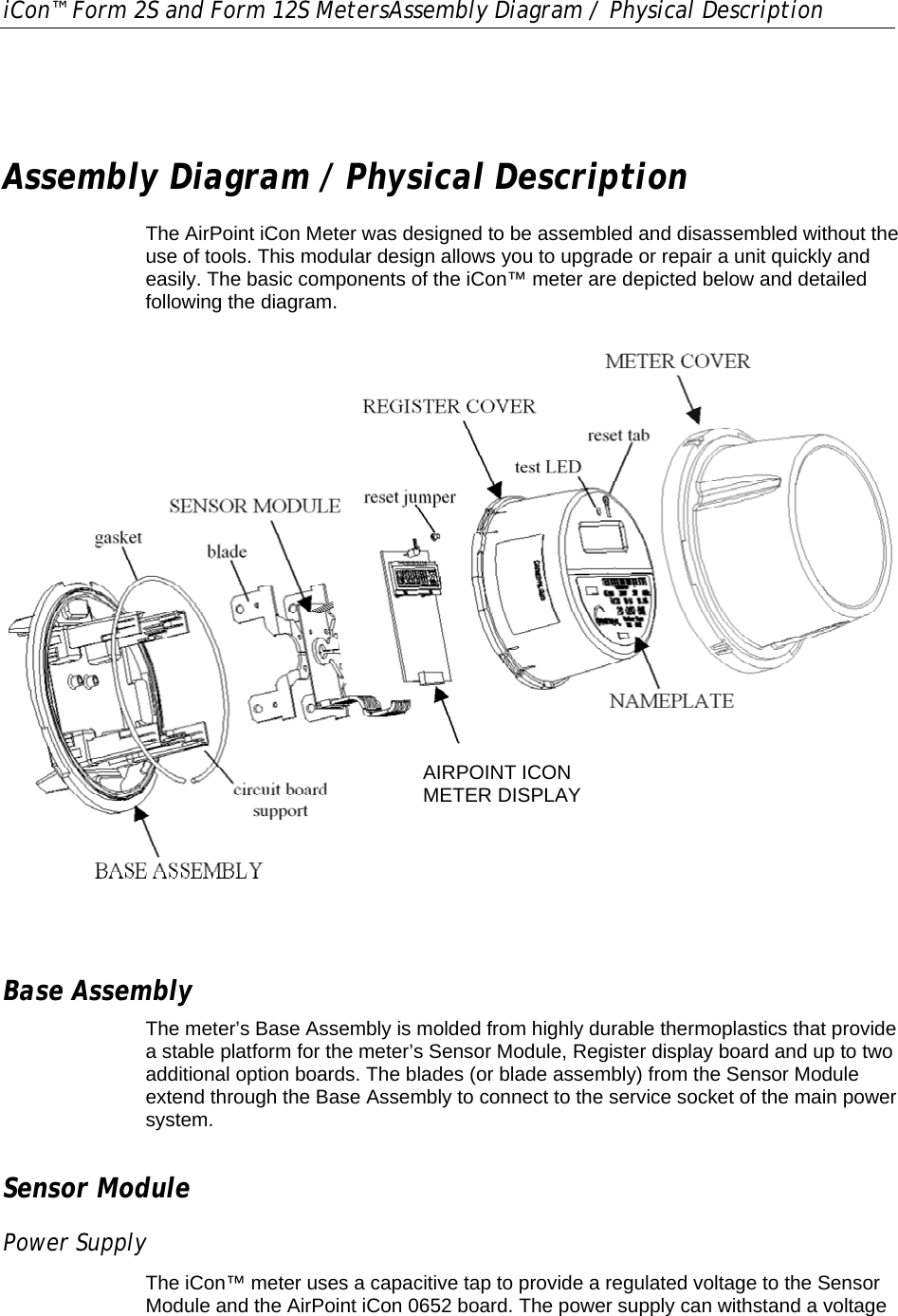
Landis Gyr Technologies AIRPT652 RF Module for Utility Meter User Manual Installation Instructions

Landis+Gyr Technologies, LLC RF Module for Utility Meter Installation Instructions

Contents

Users Manual 1

iCon™ Form 2S and Form 12S MetersAssembly Diagram / Physical Description     Assembly Diagram / Physical Description The AirPoint iCon Meter was designed to be assembled and disassembled without the use of tools. This modular design allows you to upgrade or repair a unit quickly and easily. The basic components of the iCon™ meter are depicted below and detailed following the diagram.  MXU 530-EDISPLAY BOARDPOWER SUPPLY BOARD Base Assembly The meter’s Base Assembly is molded from highly durable thermoplastics that provide a stable platform for the meter’s Sensor Module, Register display board and up to two additional option boards. The blades (or blade assembly) from the Sensor Module extend through the Base Assembly to connect to the service socket of the main power system.  Sensor Module Power Supply  The iCon™ meter uses a capacitive tap to provide a regulated voltage to the Sensor Module and the AirPoint iCon 0652 board. The power supply can withstand a voltage AIRPOINT ICON METER DISPLAY
Assembly Diagram / Physical Description  iCon™ Form 2S and Form 12S Meters transient as described in IEEE C62.41, Level C and applied in accordance with Section 5 of the ANSI C12.20-1998. Current Sensor Current is measured using a proprietary air-coupled current transformer. Sensor data, quantities proportional to the time derivative of the current, is streamed to the on-board metering chip. AirPoint iCon RF Board / Meter Display The RF Board / Meter Display consists of the AirPoint iCon radio board which is a frequency hopping radio operating in the 913.75MHz to 916.25MHz range.  An LCD display is used to display the readings collected from the Sensor Module.  Register Cover The Register Cover is an opaque shield that protects the meter’s internal boards from external tampering and serves as the mounting surface for the nameplate. With the exception of the LCD screen and test LED, no internal components can be viewed through the Register Cover. Nameplate The meter’s nameplate, which is compliant with ANSI C12.10 – 1997, includes a unique, factory-generated bar code that can be used in a billing database. Meter Cover  The Meter Cover of each iCon™ meter unit is a transparent polycarbonate enclosure that is interchangeable, abrasion resistant, and contains UV inhibitors to prevent discoloration. This single-piece assembly locks with the Base Assembly to fully enclose the meter and protect the internal components from weather, the forces applied during installation and extraction, and the impact from a fall of up to five feet. After final calibration at the factory, the Meter Cover and Base Assembly are sealed with a T-bar, which will provide evidence of tampering.

Navigation menu