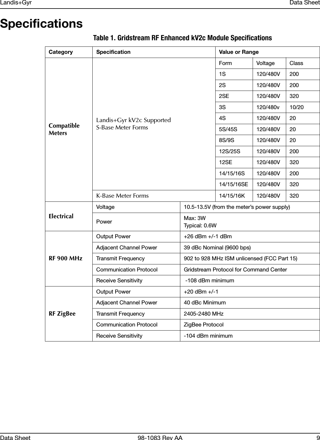
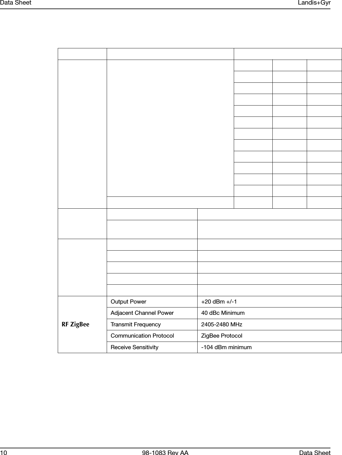
Landis Gyr Technologies HUNTGS10122 Utility Meter Transceiver Module User Manual 98 1083

Landis+Gyr Technologies, LLC Utility Meter Transceiver Module 98 1083

Manual

LANDIS+GYR CONFIDENTIAL INFORMATIONLandis+Gyr Gridstream RFEnhanced kV2c EndpointData SheetPublication: 98-1083 Rev AA
Limitation on Warranties and LiabilityInformation in this document is subject to change without notice. This manual or any part of it thereof may not be re-produced in any form unless permitted by contract or by written permission of Landis+Gyr.In no event will Landis+Gyr be liable for any incidental, indirect, special, or consequential damages (including lost prof-its) arising out of or relating to this publication or the information contained in it, even if Landis+Gyr has been advised, knew, or should have known of the possibility of such damages.© 2011 Landis+Gyr, Inc. All Rights ReservedLandis+Gyr Gridstream RF Enhanced kV2c Endpoint Quick Data SheetPublication: 98-1083 Rev AARevision HistoryModification Date Revision Description Author12/5/2011 AA Work in progress Kim UteschLandis+Gyr6436 County Road 11Pequot Lakes, MN 56472Website: www.landisgyr.comE-mail: solutionsupport.na@landisgyr.comTechnical Support: 1-888-390-5733© 2011 Landis+GyrAll rights reserved.
Data Sheet 98-1083 Rev AA 3Landis+Gyr Gridstream RFEnhanced kV2c EndpointData SheetEndpoint OverviewLandis+Gyr Gridstream RF Enhanced kV2c EndpointFigure 1.  kV2c EndpointThis communication module is not available as a stand alone product. To order a Gridstream RF Enhanced kV2c Endpoint, the Landis+Gyr kit number is 45-6100 with ZigBee or 45-6101 without ZigBee.The endpoint assembly contains:•High Speed GE kV2c Meter•Communications Module•Antenna AssemblyCONTAINS FCC ID: TEB-HUNTSG10122  CONTAINS IC: 5931A-HUNTGS10122MODEL 40-6100XXXXXXXX
Data Sheet Landis+Gyr4 98-1083 Rev AA Data SheetFCC Compliance InformationModel: 40-6100 (Forms 1S, 2S, 9S, 12S, 16S, 45S)FCC ID:TEB-HUNTGS10122Module: 10122Industry CanadaUnder Industry Canada regulations, this radio transmitter may only operate using an antenna of a type and maximum (or lesser) gain approved for the transmitter by Industry Canada. To reduce potential radio interference to other users, the antenna type and its gain should be so chosen that the equivalent isotropically radiated power (e.i.r.p.) is not more than that necessary for successful communication.Cet appareillage numérique de la classe B répond à toutes les exigences de l'interférence canadienne causant des règlements d'équipement. L'opération est sujette aux deux conditions suivantes: (1) ce dispositif peut ne pas causer l'interférence nocive, et (2) ce dispositif doit accepter n'importe quelle interférence reçue, y compris l'interférence qui peut causer l'opération peu désirée.Pour réduire le risque d'interférer avec d'autres utilisateurs, le type d'antenne et son gain doivent être choisis de telle sorte que la Puissance Isotrope Rayonnée Equivalente (P.I.R.E) ne soit pas supérieure à celle autorisée pour une communication réussie.Compliance Statement (Part 15.19)This device complies with Part 15 of the FCC Rules. Operation is subject to the following two conditions:1. This device may not cause harmful interference, and2.  This device must accept any interference received, including interference that may cause undesired operation.UWARNING: Changes or modifications not expressly approved by Landis+Gyr for compliance could void the user’s authority to operate the equipment.Endpoint LocationTo comply with FCC’s RF exposure limits for general population/uncontrolled exposure, the antenna(e) used for this transmitter must be installed to provide a separation distance of at least 20 cm from all persons and must not be collocated or operating in conjunction with any other antenna or transmitter.Endpoint UsageThe Gridstream RF FOCUS AX Integrated endpoint will be used for residential and light commercial metering applications.The Gridstream RF FOCUS AX Integrated endpoint requires professional installation by qualified personnel.
Landis+Gyr Data SheetData Sheet 98-1083 Rev AA 5RF InterferenceThis equipment has been tested and found to comply with the limits for a Class B digital device, pursuant to part 15 of the FCC Rules. These limits are designed to provide reasonable protection against harmful radio frequency energy and, if not installed and used in accordance with the instructions, may cause harmful interference to radio communications. However, there is no guarantee that interference will not occur in a particular installation. If this equipment does cause harmful interference to radio or television reception, which can be determined by turning the meter off, the user is encouraged to try to correct the interference by one or more of the following measures: 1. Re-orient or relocate the receiving antenna.2. Increase the separation between the equipment and receiver.3. Consult Landis+Gyr or an experienced radio/TC technician for help.Required SoftwareTo work with the endpoint, you need one of the following software tools:•Command Center version 5.5 or later.•RadioShop version XX or later•Endpoint Testing Manager version XX or laterAbout the LAN IDThe LAN ID is a unique identifier for each endpoint. It always displays in hex. Landis+Gyr provides the LAN address. You cannot change the LAN ID of a radio.LabelsThe endpoint includes the following labels.Figure 2.  Label IdentificationMODEL 40-6100XXXXXXXXXXXXXXXXGE #103X942001 ww/yy40-6100REV XXMODEL 40-6101XXXXXXXXXXXXXXXXGE #103X942001 ww/yy40-6101REV XX
Data Sheet Landis+Gyr6 98-1083 Rev AA Data Sheet1. LAN ID, includes programmed module part number (printed and barcoded)2. Product ID (printed and barcoded)3. FCC ID:TEB-HUNTGS101224. ICC ID: 5931A- HUNTGS10122Features and FunctionsUsing the GE High Speed kV2c Meter with the Gridstream RF kV2c Enhanced endpoint, you can:•Integrate the endpoint into all forms, classes and voltages of the GE kV2c meter.•Communicate via serial connection between the endpoint and the meter through the meter's provided interface.•Support all levels of meter passwords.•Download radio firmware.AMR InterfaceThe integrated connection contains:•Three-wire, bi-directional serial interface•Baud rate is 9600, 8 bits, 1 stop bit, no hardware hand-shaking.•Power fail indication signal from the meter that tells the endpoint to disconnect from drawing power from the meter.•DC power line which supplies power to the module from the meter.RegistrationEndpoint firmware version XXX or later and module Device Control Word (DCW) XXX or later is required for auto-registration. After the meter/endpoint is installed in the field it will automatically register with the Head End System. No special tools are needed during installation as the normal Utility meter swap process can be utilized. The meter automatically sends in the registration information containing items on how the meter/endpoint is configured so the host can properly interpret the incoming data. Some of the items contained in this are as follows:•Default Gridstream RF Collector destination•Reporting interval for Register Data•Reporting interval for Interval Data•Meter's AMR-level security password•Time Synchronization parameters•GMT offset•Periodic Register Data reporting•Periodic LP Data reporting
Landis+Gyr Data SheetData Sheet 98-1083 Rev AA 7•Meter configuration informationOnce this information has been sent the meter/endpoint starts collecting and sending based on the default configuration loaded during manufacturing.Retrieving DataThe endpoint performs data retrieval from the meter on request (ORR) or autonomously (periodically reported). Availability of the following features depends on meter configuration. On Request Reads (ORR) available with this endpoint are:•Register Data (Standard Table 23) which includes consumption, demand and TOU values.•Load Profile or Interval Data (Standard Table 64).•Revenue Integrity Services which includes instantaneous measurements related to line voltage, current and phase angle.Availability of the following features depends on meter configuration. Options for periodic reported data with this module include:•Register Data & Status Flags (Standard Tables 23 & 3) which includes consumption, demand, TOU values and meter status.•Load Profile or Interval Data & Status Flags (Standard Tables 64 & 3) which includes interval data and meter status.Demand ResetWhen Command Center Host delivers a Demand Reset command, the communication module passes the command to the meter, which performs the Demand Reset on the meter. The meter/endpoint then passes the previous demand data captured by the meter (Standard Table 25) to the Host for processing.Time SynchronizationTime syncronization is the process of keeping the meter time synchronized with the Gridstream RF network time within a configurable limit. The communication module automatically keeps its time synchronized with the Gridstream RF network via periodic background process. The communication module reads the meter date/clock table (Standard Table 52) periodically, determined by its configuration. If the time drift between the meter and communication module exceeds the configured threshold, it sends a time synchronization alert message to the Host. The Host schedules a time change event for the meter and sends it to the communication module. The time of the change is determined such that the meter’s data integrity is maintained. At the scheduled time, the communication module executes the standard procedure to change date/time on the meter.Power Outage/RestorationWhen an outage occurs, the meter uses an early power failure signal to alert the communication module to disconnect from the meter's power immediately. The communication module saves critical module data to non-volatile memory and creates and sends a power outage message. This message includes the following information:
Data Sheet Landis+Gyr8 98-1083 Rev AA Data Sheet•LAN ID•Outage time•Reboot count.The endpoint sends the message, then assists with routing other packets until the back-up energy source can no longer keep the radio alive. The time that this energy source is available varies with several factors, including amount of data packets being routed, environmental conditions and age of meter/endpoint. Generally, a hold-up time of ~45 seconds is typical. At restoration, the communication module first acquires network connectivity. With network communications restored, the endpoint sends a power restoration message that includes details such as: •LAN ID•Outage time•Restoration time•Reboot count.The communications module stores a history of up to the last five power outage and restoration event pairs. The Host can request this data.Supporting PasswordsThe meter/endpoint supports passwords provided by the utility. See publication 98-1055 Gridstream 2-way Endpoint Testing Manager User Guide for information regarding loading password into module.Downloading Firmware Enable meter firmware remotely via RadioShop. The module can remotely initiate a self-restart with communications enabled, if the downloaded firmware causes a catastrophic functional failure. Once the endpoint completely receives the new code, it operates with the new code.Encrypting DataThe Gridstream RF Network currently supports use of one encryption key per network. If you enable the GE High Speed kV2c with encryption, the host must have a matching encryption key.
Landis+Gyr Data SheetData Sheet 98-1083 Rev AA 9SpecificationsTable 1. Gridstream RF Enhanced kV2c Module SpecificationsCategory Specification Value or RangeCompatible MetersLandis+Gyr kV2c SupportedS-Base Meter FormsForm Voltage Class1S 120/480V 2002S 120/480V 2002SE 120/480V 3203S 120/480v 10/204S 120/480V 205S/45S 120/480V 208S/9S 120/480V 2012S/25S 120/480V 20012SE 120/480V 32014/15/16S 120/480V 20014/15/16SE 120/480V 320K-Base Meter Forms 14/15/16K 120/480V 320ElectricalVoltage 10.5-13.5V (from the meter’s power supply)Power Max: 3WTypical: 0.6WRF 900 MHzOutput Power +26 dBm +/-1 dBmAdjacent Channel Power 39 dBc Nominal (9600 bps)Transmit Frequency 902 to 928 MHz ISM unlicensed (FCC Part 15)Communication Protocol Gridstream Protocol for Command CenterReceive Sensitivity  -108 dBm minimumRF ZigBeeOutput Power +20 dBm +/-1Adjacent Channel Power 40 dBc MinimumTransmit Frequency 2405-2480 MHzCommunication Protocol ZigBee ProtocolReceive Sensitivity -104 dBm minimum
Data Sheet Landis+Gyr10 98-1083 Rev AA Data SheetRF ZigBeeOutput Power +20 dBm +/-1Adjacent Channel Power 40 dBc MinimumTransmit Frequency 2405-2480 MHzCommunication Protocol ZigBee ProtocolReceive Sensitivity -104 dBm minimum

Navigation menu