Landis Gyr Technology 26-1129-01 InfiNet Concentrator User Manual users manual
Landis+Gyr Technology, Inc. InfiNet Concentrator users manual
users manual

5015 B.U. Bowman Drive Buford, GA 30518 USA Voice: 770-831-8048 Fax: 770-831-8598
FCC Part 15 Subpart C
Transmitter Certification
Composite Device
Test Report
FCC ID: R7P26-1129-01
FCC Rule Part: 15.247
ACS Report Number(s):
05-0384-15C-DSS
05-0384-15C-DTS
Manufacturer: Cellnet Technology, Inc.
Trade Name: InfiNet Concentrator
Model: 26-1129
Installation Guide
Title: SOP Concentrator Installation
Doc. Number: XX-XXXX Revision: 01 Page 1 of 18
© Cellnet 2006, All rights reserved.
Revision History
ECO/ECN Rev Date Author Page Description
XXXXX 01 G. Farmer ALL INITIAL RELEASE
02 H.Glass

Title: SOP Concentrator Installation
Doc. Number: XX-XXXX Revision: 01 Page 2 of 18
© Cellnet 2006, All rights reserved.
Proprietary Rights Notice
The information contained in this document is subject to change without notice. Cellnet reserves the
right to change the product specifications at any time without incurring any obligations.
Trademarks Used in This Manual
UtiliNet® is a trademark of Cellnet Innovations, Inc.
Cellnet® is a registered trademark of Cellnet Innovations, Inc.

Title: SOP Concentrator Installation
Doc. Number: XX-XXXX Revision: 01 Page 3 of 18
© Cellnet 2006, All rights reserved.
FCC Information
This device complies with part 15 of the FCC rules. Operation is subject to the following two conditions:
This device may not cause harmful interference, and
This device must accept any interference received, including interference that may cause undesired
operation.
FCC Part 15.247 Operation within the bands 902-928 MHz, 2400-2483.5 MHz, and 5725-5850 MHz.
(a) Operation under the provisions of this section is limited to frequency hopping and direct sequence spread
spectrum intentional radiators that comply with the following provisions:
(1) Frequency hopping systems shall have hopping channel carrier frequencies separated by a minimum of
25 kHz or the 20 dB bandwidth of the hopping channel, whichever is greater. The system shall hop to
channel frequencies that are selected at the system hopping rate from a pseudo-randomly ordered list of
hopping frequencies. Each frequency must be used equally on the average by each transmitter. The system
receivers shall have input bandwidths that match the hopping channel bandwidths of their corresponding
transmitters and shall shift frequencies in synchronization with the transmitted signals.
(i) For frequency hopping systems operating in the 902-928 MHz band: if the 20 dB bandwidth of the hopping
channel is less than 250 kHz, the system shall use at least 50 hopping frequencies and the average time of
occupancy on any frequency shall not be greater than 0.4 seconds within a 20 second period; if the 20 dB
bandwidth of the hopping channel is 250 kHz or greater, the system shall use at least 25 hopping
frequencies and the average time of occupancy on any frequency shall not be greater than 0.4 seconds
within a 10 second period. The maximum allowed 20 dB bandwidth of the hopping channel is 500 kHz.
(ii) Frequency hopping systems operating in the 2400-2483.5 MHz and 5725-5850 MHz
bands shall use at least 75 hopping frequencies. The maximum 20 dB bandwidth of the hopping channel is 1
MHz. The average time of occupancy on any frequency shall not be greater than 0.4 seconds within a 30
second period.
(iii) Frequency hopping systems in the 2400-2483.5 MHz band may utilize hopping channels whose 20 dB
bandwidth is greater than 1 MHz provided the systems use at least 15 non-overlapping channels. The total
span of hopping channels shall be at least 75 MHz. The average time of occupancy on any one channel
shall not be greater than 0.4 seconds within the time period required to hop through all channels.
(2) For direct sequence systems, the minimum 6 dB bandwidth shall be at least 500 kHz.
(b) The maximum peak output power of the intentional radiator shall not exceed the following:
(1) For frequency hopping systems in the 2400-2483.5 MHz band employing at least 75 hopping channels,
all frequency hopping systems in the 5725-5850 MHz band, and all direct sequence systems: 1 watt. For all
other frequency hopping systems in the 2400-2483.5 MHz band: 0.125 watts.
(2) For frequency hopping systems operating in the 902-928 MHz band: 1 watt for systems employing at
least 50 hopping channels; and, 0.25 watts for systems employing less than 50 hopping channels, but at
least 25 hopping channels, as permitted under paragraph
(a)(1)(i) of this section.
(3) Except as shown in paragraphs (b)(3) (i), (ii) and (iii) of this section, if transmitting antennas of directional
gain greater than 6 dBi are used the peak output power from the intentional radiator shall be reduced below
the stated values in paragraphs (b)(1) or (b)(2) of this section, as appropriate, by the amount in dB that the
directional gain of the antenna exceeds 6 dBi.

Title: SOP Concentrator Installation
Doc. Number: XX-XXXX Revision: 01 Page 4 of 18
© Cellnet 2006, All rights reserved.
(i) Systems operating in the 2400-2483.5 MHz band that are used exclusively for fixed, point-to-point
operations may employ transmitting antennas with directional gain greater than 6 dBi provided the maximum
peak output power of the intentional radiator is reduced by 1 dB for every 3 dB that the directional gain of the
antenna exceeds 6 dBi.
(ii) Systems operating in the 5725-5850 MHz band that are used exclusively for fixed, point-to-point
operations may employ transmitting antennas with directional gain greater than 6 dBi without any
corresponding reduction in transmitter peak output power.
(iii) Fixed, point-to-point operation, as used in paragraphs (b)(3)(i) and (b)(3)(ii) of this section, excludes the
use of point-to-multipoint systems, omnidirectional applications, and multiple co-located intentional radiators
transmitting the same information. The operator of the spread spectrum intentional radiator or, if the
equipment is professionally installed, the installer is responsible for ensuring that the system is used
exclusively for fixed, point-to-point operations. The instruction manual furnished with the intentional radiator
shall contain language in the installation instructions informing the operator and the installer of this
responsibility.
(4) Systems operating under the provisions of this section shall be operated in a manner that ensures that
the public is not exposed to radio frequency energy levels in excess of the Commission's guidelines.
(c) In any 100 kHz bandwidth outside the frequency band in which the spread spectrum intentional radiator is
operating, the radio frequency power that is produced by the intentional radiator shall be at least 20 dB
below that in the 100 kHz bandwidth within the band that contains the highest level of the desired power,
based on either an RF conducted or a radiated measurement. Attenuation below the general limits specified
in Sec. 15.209(a) is not required. In addition, radiated emissions which fall in the restricted bands, as defined
in Sec. 15.205(a), must also comply with the radiated emission limits specified in Sec. 15.209(a)
(d) For direct sequence systems, the peak power spectral density conducted from the intentional radiator to
the antenna shall not be greater than 8 dBm in any 3 kHz band during any time interval of continuous
transmission. (e) The processing gain of a direct sequence system shall be at least 10 dB. The processing
gain represents the improvement to the received signal-to-noise ratio, after filtering to the information
bandwidth, from the spreading/despreading function. The processing gain may be determined using one of
the following methods:
(1) As measured at the demodulated output of the receiver: the ratio in dB of the signal-to-noise ratio with the
system spreading code turned off to the signal-to-noise ratio with the system spreading code turned on.
(2) As measured using the CW jamming margin method: a signal generator is stepped in 50 kHz increments
across the passband of the system, recording at each point the generator level required to produce the
recommended Bit Error Rate (BER). This level is the jammer level. The output power of the intentional
radiator is measured at the same point. The jammer to signal ratio (J/S) is then calculated, discarding the
worst 20% of the J/S data points. The lowest remaining J/S ratio is used to calculate the processing gain, as
follows: Gp = (S/N) o + Mj + Lsys, where Gp = processing gain of the system, (S/N) o = signal to noise ratio
required for the chosen BER, Mj = J/S ratio, and Lsys = system losses. Note that total losses in a system,
including intentional radiator and receiver, should be assumed to be no more than 2 dB.
(f) Hybrid systems that employ a combination of both direct sequence and frequency hopping modulation
techniques shall achieve a processing gain of at least 17 dB from the combined techniques. The frequency
hopping operation of the hybrid system, with the direct sequence operation turned off, shall have an average
time of occupancy on any frequency not to exceed 0.4 seconds within a time period in seconds equal to the
number of hopping frequencies employed multiplied by 0.4. The direct sequence operation of the hybrid
system, with the frequency hopping operation turned off, shall comply with the power density requirements of
paragraph (d) of this section.
Title: SOP Concentrator Installation
Doc. Number: XX-XXXX Revision: 01 Page 5 of 18
© Cellnet 2006, All rights reserved.
(g) Frequency hopping spread spectrum systems are not required to employ all available hopping channels
during each transmission. However, the system, consisting of both the transmitter and the receiver, must be
designed to comply with all of the regulations in this section should the transmitter be presented with a
continuous data (or information) stream. In addition, a system employing short transmission bursts must
comply with the definition of a frequency hopping system and must distribute its transmissions over the
minimum number of hopping channels specified in this section.
(h) The incorporation of intelligence within a frequency hopping spread spectrum system that permits the
system to recognize other users within the spectrum band so that it individually and independently chooses
and adapts its hopsets to avoid hopping on occupied channels is permitted. The coordination of frequency
hopping systems in any other manner for the express purpose of avoiding the simultaneous occupancy of
individual hopping frequencies by multiple transmitters is not permitted. Note: Spread spectrum systems are
sharing these bands on a noninterference basis with systems supporting critical Government requirements
that have been allocated the usage of these bands, secondary only to ISM equipment operated under the
provisions of part 18 of this chapter. Many of these Government systems are airborne radiolocation systems
that emit a high EIRP which can cause interference to other users. Also, investigations of the effect of spread
spectrum interference to U. S. Government operations in the 902-928 MHz band may require a future
decrease in the power limits allowed for spread spectrum operation.
Industry Canada
This Class B digital apparatus meets all requirements of the Canadian Interference Causing Equipment
Regulations. Operation is subject to the following two conditions: (1) this device may not cause harmful
interference, and (2) this device must accept any interference received, including interference that may cause
undesired operation.
Cet appareillage numérique de la classe B répond à toutes les exigences de
l'interférence canadienne causant des règlements d'équipement. L'opération est sujette aux deux conditions
suivantes: (1) ce dispositif peut ne pas causer l'interférence nocive, et (2) ce dispositif doit accepter n'importe
quelle interférence reçue, y compris l'interférence qui peut causer l'opération peu désirée.

Title: SOP Concentrator Installation
Doc. Number: XX-XXXX Revision: 01 Page 6 of 18
© Cellnet 2006, All rights reserved.
INFORMATION TO THE USER
FCC Class B
NOTE: This equipment has been tested and found to comply with the limits for a Class B digital device,
pursuant to Part 15 of the FCC Rules. These limits are designed to provide reasonable protection against
harmful interference in a residential installation. This equipment generates, uses, and can radiate radio
frequency energy and, if not installed and used in accordance with the Instructions, may cause harmful
interference to radio communications. However, there is no guarantee that interference will not occur in a
particular installation. If this equipment does cause harmful interference to radio or television reception,
which can be determined by turning the equipment off and on, the user is encouraged to try to correct the
interference by one or more of the following
measures:
• Reorient or relocate the receiving antenna.
• Increase the separation between the equipment and receiver.
• Connect the equipment into an outlet on a circuit different from that to which the receiver is connected.
• Consult the dealer or an experienced radio/TV technician for help.
Warning: Changes or modifications to this device not expressly approved Cellnet Technology, Inc.
could void the user’s authority to operate the equipment.
RF Exposure
In accordance with FCC requirements of human exposure to radiofrequency fields, the radiating element
shall be installed such that a minimum separation distance of 20 centimeters. This device must not be co-
located or operating in conjunction with any other antenna or transmitter.

SOP Utilinet Concentrator Installation
XX-XXXX, Rev: 01 Page 7 of 18
© Cellnet 2006. All rights reserved.
Contents
Contents……………………………………………………..………………..2
Figures………………………………………………………..…………….…2
Acronyms…………………………………………………….….………….…2
Related Documents…………………………………………………………..3
1.1 Cellnet Network………………………………………….………………..3
1.2 Concentrator Antenna
options……………………………………….………………3
1.3 Concentrator
programming…………………………………………………………...3
2.0 Required Tools & Materials……………………………………………...3
2.1 Contractor-provided tools………………………………………………..4
2.2 Contractor-provided material……………………………………………4
3.0 Customer Notification/Authorization……………………………………5
3.1 Appointment for building access………………………………………….5
3.2 Utility or municipal authorization for pole attachment…………………..5
4.0 Site location and verification………………………………………………5
4.1 Site verification……………………………………………………………...5
4.2 Bucket trucks………………………………………………………………..6
5.0 Installation…………………………………………………………………...6
5.1 General………………………………………………………………………6
5.2 Power Requirements………………………………………………………..6
5.3 Power connections………………………………………………………….6
5.4 Concentrator Mechanical
mounting………………………………………………….…7
5.4.1 Street light pole (other than wood)………………………………………7
5.4.2 Wood utility pole………………………………………………………….10
5.4.2.1 Power cable preparation………………………………………………11
Figures
Fig. 1…………………………………………………………………………………8
Fig. 2…………………………………………………………………………………9
Fig. 3………………………………………………………………………………..10
Fig. 4..………………………………………………………………………………11
Fig. 5………………………………………………………………………………..12
SOP Utilinet Concentrator Installation
XX-XXXX, Rev: 01 Page 8 of 18
© Cellnet 2006. All rights reserved.
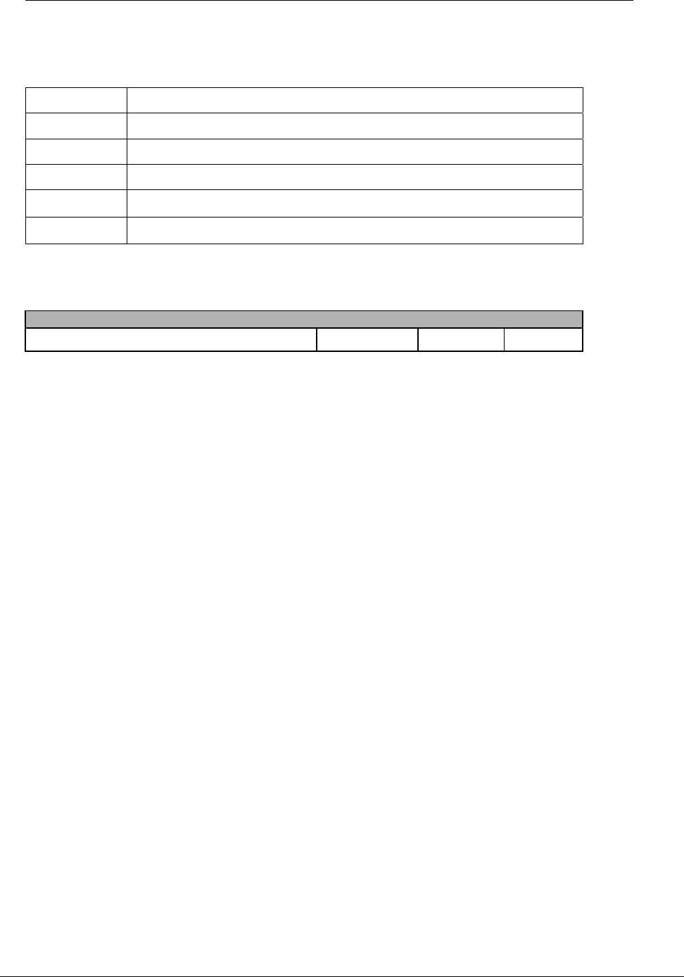
Acronyms
Concentrator Infinet Concentrator
LAN Local Area Network (modules)
NOC Network Operations Center in Lenexa, Kansas
TOP Take Out Point (communicates with Concentrator’s)
WAN Wide Area Network (Concentrator to TOP)
Related Documents
Document Title Part Number Revision Date
Concentrator programming guide

SOP Utilinet Concentrator Installation
XX-XXXX, Rev: 01 Page 9 of 18
© Cellnet 2006. All rights reserved.
1.1 Cellnet Network (General Overview)
The CellNet Automated Metering Infrastructure network is used to transfer information from a
number of endpoints usually distributed over a large geographical area. The most common
endpoints are from electrical, gas and water meters. The network includes a Radio Frequency
(RF) Wide Area Network (WAN) and an RF Local Area Network (LAN). The WAN consists of
Take Out Points (TOP) and Infinet Concentrators (Concentrator). The LAN is the RF link
between the InfiNet Concentrator and meters with CellNet meter modules installed. The endpoint
data is transmitted via a radio frequency (RF) link to the Concentrator where it is stored and
processed. The Concentrator then transmits this via a RF link to the TOP and then to the host
system for the utility to pick up. This document deals with the installation of Concentrators.
1.2 Concentrator Antenna options
The Concentrator requires three antennas to communicate with the meters and to relay
information from the endpoint to the Network Operations Center. Two 17" whip LAN antennas
(receive-only) mount on the side of the enclosure. An additional antenna for WAN
communications will mount either on the top of the enclosure or all three antennas can be remote
from the Concentrator such as the top of a utility pole or a building parapet. If the three antennas
are mounted above the enclosure, coaxial cable will connect the enclosure and the remote
antennas.
Cellnet recognizes that the performance of the radio can vary depending on the characteristics of
a particular of installation. For your convenience, this guide to antenna installations is included.
When installed properly by a radio communications professional, the approved equipment will
assure maximum performance of 902-928 MHz radio products.
There are a number of reputable companies that sell antennas and related equipment. While
Cellnet does not make an exclusive recommendation on which company would be appropriate for
a particular installation, Talley Communications is a supplier that Cellnet has worked with
extensively. In each section, references to Talley part numbers are included as an example for
your convenience.
Talley Communications
12976 Sandoval Street
Santa Fe Springs, CA 90670
Tel: (800) 223-4949
utilnet@talleycom.com
Approved Antennas:
Note: Only these antennas are authorized for used with these transmitters.
Talley Communications (800-223-4949):
3 db gain omni-directional remote mount whip antenna REMOTE-OMNI3 Antenex,
3 db gain omni-directional direct mount whip antenna DIRECT-OMNI3 Antenex
This document presents basic guidelines for the user’s selection of antenna equipment. The
antenna purchase and/or use decision and equipment installation is the responsibility of the
user. Cellnet makes no warranty representation, either expressed or implied, regarding
equipment performance or its suitability for the user’s intended purpose.
UtiliNet Series III radios' power output plus the antenna gain must be equal or less than the

SOP Utilinet Concentrator Installation
XX-XXXX, Rev: 01 Page 10 of 18
© Cellnet 2006. All rights reserved.
Maximum Effective Isotropic Radiated Power (EIRP), +36 dBm, established by the FCC. User
must adjust the power output and select the antenna gain to comply with this requirement.
Industry Canada:
This device has been designed to operate with the antennas listed above, and having a maximum
gain of 6 dBi. Antennas not included in this list or having a gain greater than 6 dBi are strictly
prohibited for use with this device. The required antenna impedance is 50 ohms.
To reduce potential radio interference to other users, the antenna type and its gain should be so
chosen that the equivalent isotropically radiated power (EIRP) is not more than that required for
successful communication.
1.3 Concentrator programming
Programming of the Concentrator is required prior to installation. The Concentrator programming
process consists of entering GPS and other required parameters into the radio. This task is best
done in batch mode where the Concentrators are stored prior to field deployment for installation.
For the purposes of this SOP, it is assumed that the programming has already been completed
and the information provided with work order/installation sheet. The Concentrator will typically be
labeled with the IPC address visible from the outside.
2.0 Required Tools & Materials
The following is a list of tools and materials for installing the Concentrators for utility pole and
streetlight mounting. For building and pad-mount installations, the same tools will apply with
some additional materials required. Check under the type of installation for materials and tools
needed to perform the installation.
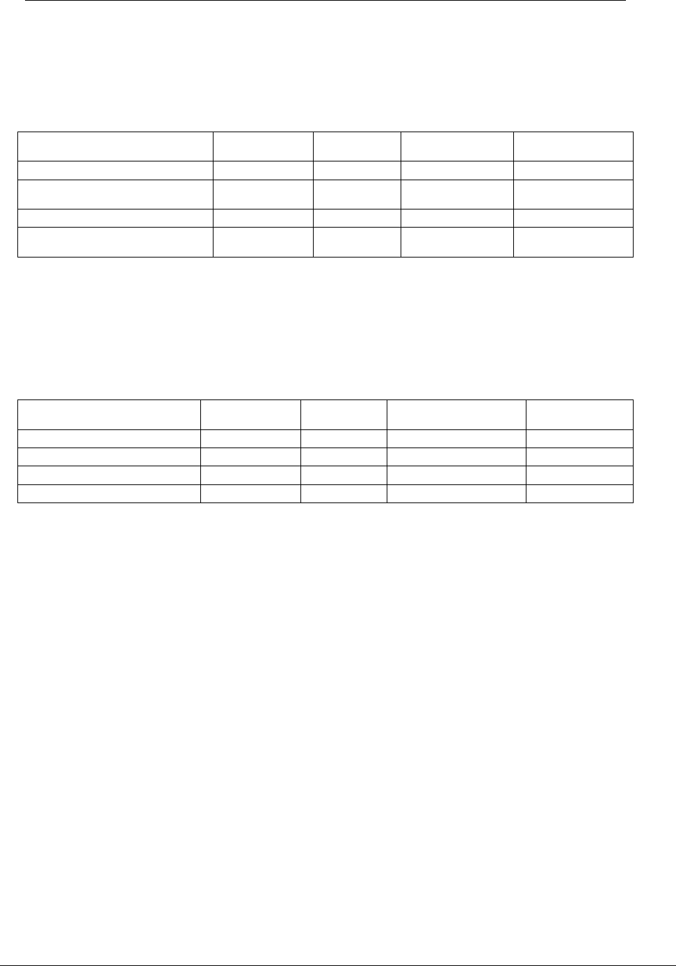
Material Provided by Cellnet Wood Utility
Pole Steel Street
Light Pole Building & Structure
Install Pad-mount
XFMR
Concentrators (Concentrators) X X X X
LAN omni whip antennas X X X X
WAN omni whip antenna X X X X
Streetlight head adapter X
RF coaxial cables** X X X X
AC power quick disconnect
connector with 8 ft. or 18 ft. wire
attached X X X X
Female N – bulkhead connectors X X X
MCC strap mounting brackets X
** These come in different lengths, 5, 10, 15, 20, and 25, are most commonly used
SOP Utilinet Concentrator Installation
XX-XXXX, Rev: 01 Page 11 of 18
© Cellnet 2006. All rights reserved.
2.1 Contractor-provided tools
The following table contains specific tools required for the installation of Concentrators on the four
primary installation types. The contractor shall also provide typical tools required for mechanical
and electrical installations such as normal lineman tools, wire cutters, hammer, assorted screw
drivers, socket set, wrenches, voltmeter, compass, tape measure, etc.
Tools Provided by Contractor Wood Utility
Pole Steel Street
Light Pole Building &
Structure Install Pad-mount XFMR
steel banding tool X X
drill (battery, gas or electric
powered) X X X
drill bits for lag and D/A bolt X X X
Laptop computer with serial
port* X X X X
* May not be required. Refer to statement of work or work project request.
2.2 Contractor-provided material
The following table contains specific material required for the installation of MCCs on the
four primary installation types. Note: additional material such as screws, nuts, bolts may be
required to complete installations. The contractor shall provide this material for each
installation.
Material Provided by
Contractor Wood Utility
Pole Steel Street
Light Pole Building & Structure
Install Pad-mount
XFMR
TBD
3.0 Customer Notification/Authorization
3.1 Appointment for building access
The Below statement is a placeholder until statement can be reviewed.
Cellnet shall provide a point of contact for each building that needs access by the contractor. It
shall be the contractor’s responsibility to schedule the required appointments and to make
notifications to the appropriate building owners, managers or tenants before performing the
Concentrator installation.

SOP Utilinet Concentrator Installation
XX-XXXX, Rev: 01 Page 12 of 18
© Cellnet 2006. All rights reserved.
3.2 Utility or municipal authorization for pole
attachment
The Below statement is a placeholder until statement can be reviewed.
When the Concentrator is to be located on utility or municipal property such as utility poles and
streetlight poles, Cellnet will have a general agreement in place to install on these poles. There
may be a requirement for the utility or municipal to approve individual sites. This approval will be
noted on the Concentrator installation sheet or provided in another format approved by Cellnet. It
is the contractor’s responsibility to ensure that approval has been given for each installation.
4.0 Site location and verification
4.1 Site verification
The Below statement is a placeholder until statement can be reviewed.
The contractor shall be responsible for installing the Concentrator on the correct pole or building.
The contractor should make every effort to confirm that they have the correct location.
4.2 Bucket trucks
The Below statement is a placeholder until statement can be reviewed.
The contractor shall provide a bucket truck for installations requiring them. A bucket truck is used
for most wood and streetlight pole installations. The contractor shall comply with all local traffic
ordinances while performing the Concentrator installations.

SOP Utilinet Concentrator Installation
XX-XXXX, Rev: 01 Page 13 of 18
© Cellnet 2006. All rights reserved.
5.0 Installation
NOTE: This device requires professional installation.
5.1 General
• For every Concentrator that is to be installed, an Concentrator Installation Sheet will be provided.
• The sheet has the street address, type of mounting (wood pole, streetlight pole, building, etc.),
access (bucket truck or climbed manually).
• The Concentrator uses a quick-disconnect connector that must be wired to a single phase 120
VAC or 240 VAC circuit.
5.2 Power Requirements
The Concentrator requires the following voltage: 120 VAC +/- 20% (96-144 VAC), 60 Hz +/- 1 Hz
or 240 VAC +/- 20% (192-288 VAC), 60 Hz +/- 1 Hz The Concentrator has the following current
requirements:
1 Amp max at 120VAC (Approx.)
.5 Amp typical at 120 VAC (Approx.)
5.3 Power connections
5.3.1 Verify that the power source is either 120 VAC or 240 VAC single phase.
5.3.2 Run quick-disconnect wire through liquid tight conduit with appropriate connectors.
Additional detail will be provided in following procedures for the different Concentrator installation
types.
5.4 Concentrator mechanical mounting
5.4.1 Street light pole (other than wood)
The final guidelines provided by the utility or municipality determine where the
Concentrator can be installed. It is the contractor’s responsibility to know and follow the utility or
municipality guidelines before installing the Concentrator and antenna.
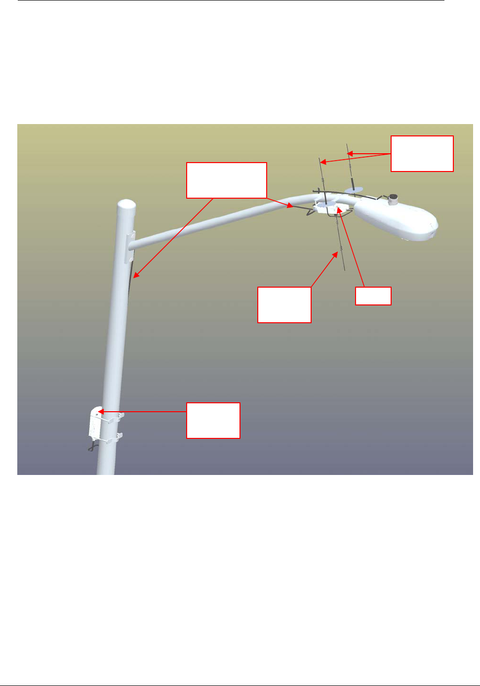
1. Using mounting kit 45-1036 mount the Concentrator on the arm of the light pole and
mount the battery pack as far down the pole as the 15 foot power cable will allow.
2. Place the brackets found in kit 45-1007 in place on the arm of the light pole. Placing the
antenna bracket (28-1031) toward the light head.
3. Using carriage bolts found in kit 45-1007 mount the Concentrator (26-1129) to the two
brackets left being aware to face the military connectors toward the metal pole. Attach
battery power cable 19-1106 to Concentrator and run along pole to where the battery
pack will be placed. Secure cable with tie wraps (22-0375).
SOP Utilinet Concentrator Installation
XX-XXXX, Rev: 01 Page 14 of 18
© Cellnet 2006. All rights reserved.
4. Using either 19-2200 or a locally created cable connect antennas (01-1239) and ground
planes to Concentrator and antenna bracket (28-1031).
5. Using kit 45-1018 or metal banding mount the BATTERY PACK (26-1136) to the light
pole as far down the pole as cable 19-1106 will allow. Attach battery power cable.
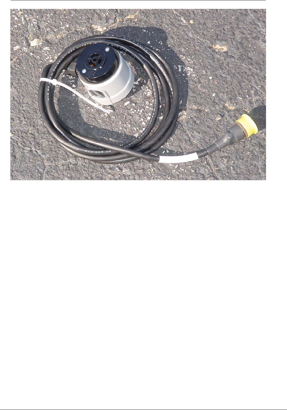
6. Using either street light adapter 103826-000 or locally created cable from one of the AC
cables listed in 5.4.2.1 and a locally procured power head attach power from light head to
Concentrator. Fig xx.
Fig. 1
Con
Battery
Pack
Interconnect
cable
WAN
antenna
Lan
antennas
SOP Utilinet Concentrator Installation
XX-XXXX, Rev: 01 Page 15 of 18
© Cellnet 2006. All rights reserved.
Fig. 2
SOP Utilinet Concentrator Installation
XX-XXXX, Rev: 01 Page 16 of 18
© Cellnet 2006. All rights reserved.
5.4.2 Wood utility pole
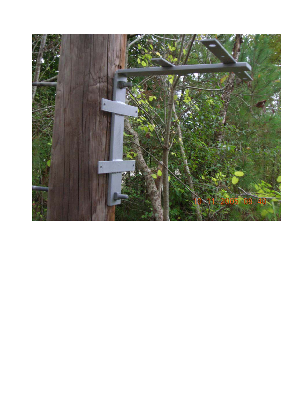
1. Using mounting kit 45-1035 mount Bracket 28-1079 to wood pole using two MCC
mounting bolts (D/A Bolts) with washer and nut.
Fig. 3
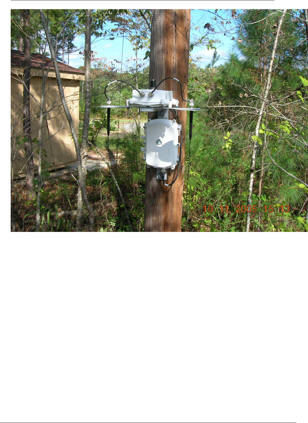
2. Attach BATTERY PACK (26-1136) to bracket using (4) carriage bolts (101887-350).
Secure with nuts (101983-025) and washers (22-0421).
3. Attach Concentrator (26-1129) to bracket, being aware to face the military connectors
toward the pole as there are weep holes in the event of condensation. Using (4) carriage
bolts (101887-350). Secure with nuts (101983-025) and washers (22-0421).
4. Connect the Battery pack to the Concentrator with battery cable (19-1125).
5. Using either 19-2200 or a locally created cable connect antennas 01-1239 and ground
planes to Concentrator and bracket (28-1079).
SOP Utilinet Concentrator Installation
XX-XXXX, Rev: 01 Page 17 of 18
© Cellnet 2006. All rights reserved.
Fig 4.
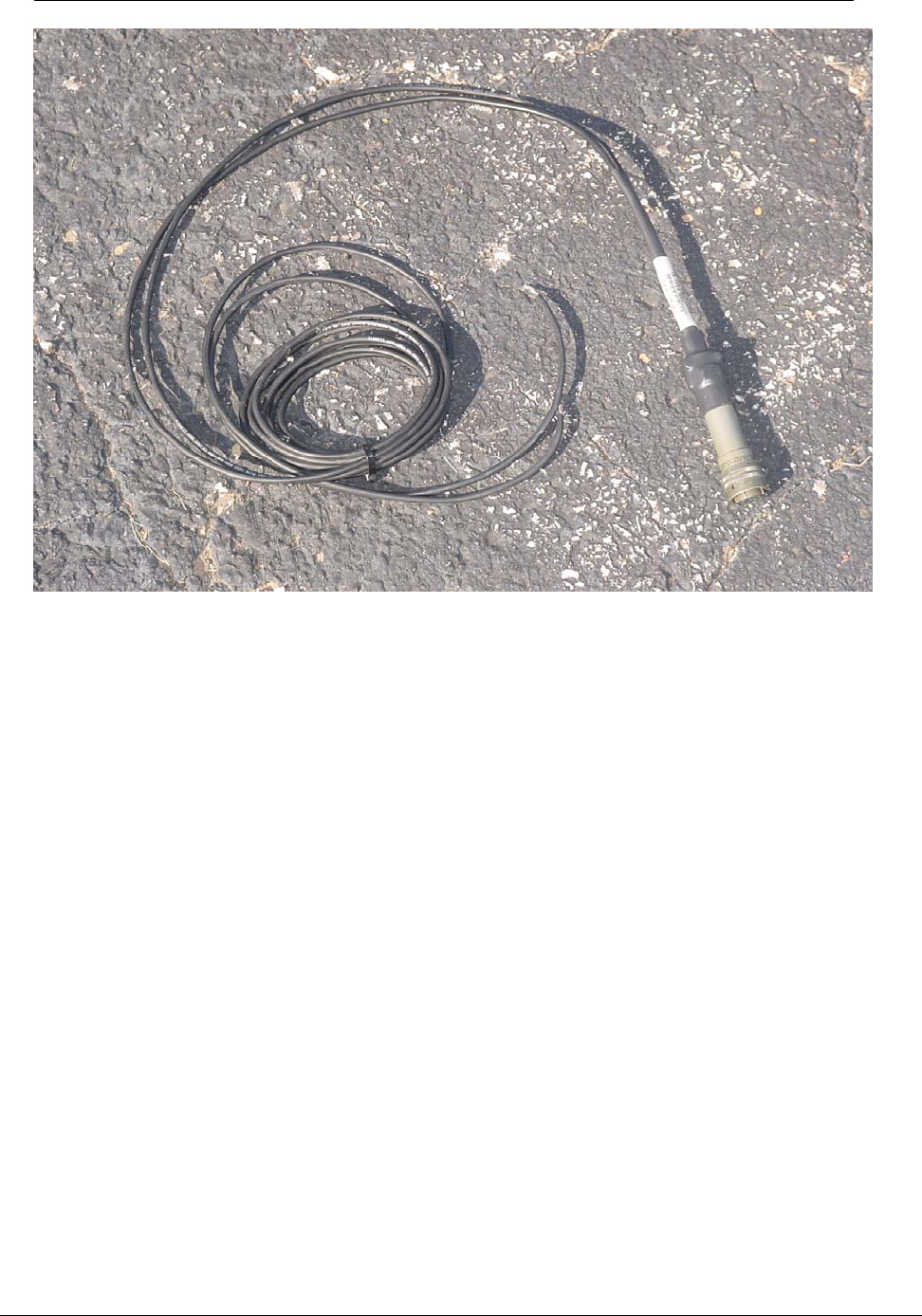
5.4.2.1 Power cable preparation
1. Cables part numbers are 105704-000 for a ten-foot cable, 105704-001 for a thirty-foot
cable, and 105704-002 for a four-foot cable.
2. Depending on the utility requirements, physically connecting to the secondary may have
additional requirements that have to be met. It is possible that the utility will do this. Take
the naked wires from the end of the liquid tight conduit and securely clamp it to the
secondary. This is a compression type fitting. Sometimes a run of secondary is needed
from an adjacent pole to provide the power for this Concentrator.
SOP Utilinet Concentrator Installation
XX-XXXX, Rev: 01 Page 18 of 18
© Cellnet 2006. All rights reserved.
Fig. 5