Landis Gyr Technology CG6R1S1 1-WAY REPEATER User Manual USERS MANUAL
Landis+Gyr Technology, Inc. 1-WAY REPEATER USERS MANUAL
UserManual.wiki
>
Landis Gyr Technology
>
CG6R1S1 User Manual
USERS MANUAL
Navigation menu
Upload a User Manual
Namespaces
Wiki Guide
HTML
PDF
Info
Views
User Manual
Discussion / Help
Navigation
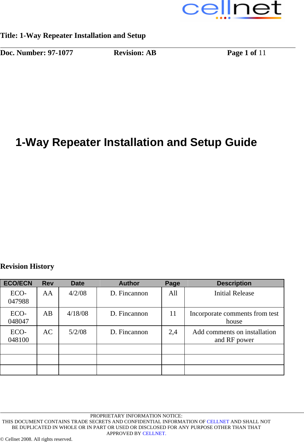
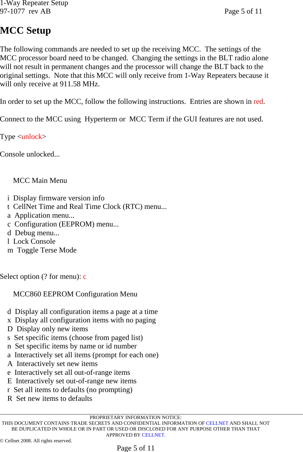
![1-Way Repeater Setup 97-1077 rev AB Page 6 of 11 PROPRIETARY INFORMATION NOTICE: THIS DOCUMENT CONTAINS TRADE SECRETS AND CONFIDENTIAL INFORMATION OF CELLNET AND SHALL NOT BE DUPLICATED IN WHOLE OR IN PART OR USED OR DISCLOSED FOR ANY PURPOSE OTHER THAN THAT APPROVED BY CELLNET. © Cellnet 2008. All rights reserved. Page 6 of 11 f Set all out-of-range items to defaults F Set out-of-range new items to defaults S Save EEPROM cache to NAND File G Get the EEPROM params from Nand q Quit Select option (? for menu): s MCC860 EEPROM Configuration [Note '*' indicates change requires Warm Boot; '+' requires Hot Boot] [a] MCC ID (up to 15 characters): INCB011 [b] MCC serial number (up to 16 characters): 1000005 [c]+MCC WAN Stack Type (0=radio, 1=serial DMS, 2=serial MTP, 3=RAM WAN, 4=Tel WAN, 5=IP WAN, 6=FreeWave, 7= Utilinet) [0..7;default=0]: 0 [d]*MCC DMS Net Address [1..4294967039;default=4294967038]: 600037 [e]*MCC DMS node address (normally 1) [1..65534;default=65534]: 12 [f]+Log manager's (and CTS's) DMS Net Address [1..4294967039;default=4294967039]: 23 [g]+Log manager's (and CTS's) DMS node address [1..65534;default=65534]: 254 [h]+Event manager's DMS Net Address [1..4294967039;default=4294967039]: 25 [i]+Event manager's DMS node address [1..65534;default=65534]: 256 [j] Event forwarding ODE timeout (seconds) [120..86400;default=1800]: 1800 [k] Event forwarding holdoff (seconds) [0..86400;default=120]: 120 [l]+Last ODE object id [1..2147483647;default=1]: 117350001 [m]*Minutes from GMT (0=GMT, 480=PST) [positive increments of 60] [-720..720;default=480]: 360 [n]*Daylight savings type (0=none, 1=USA, 7=UK) [0..7;default=1]: 1 [o]+Lan transceiver hardware revision [0..255;default=0]: 0 [p]+Lan Rx squelch [0..255;default=0]: 1 [r]+Lan Rx frequency (3 MHz steps) [905.58..926.58;default=917.58]: 917.58 [s]+Lan Rx chipping sequence [1..6;default=1]: 1 [t]+Lan Rx Trip level (0 = use transceiver default) [0..255;default=0]: 0 [u]+Lan Rx antenna (0=normal, 1=fast, 2=fixed A, 3=fixed B) [0..3;default=0]: 0 <Look for letter corresponding to Lan Rx frequency and Lan Rx chipping sequence>](https://usermanual.wiki/Landis-Gyr-Technology/CG6R1S1/User-Guide-936965-Page-7.png)
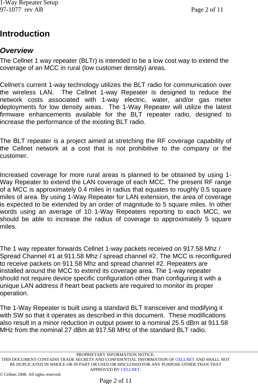
![1-Way Repeater Setup 97-1077 rev AB Page 7 of 11 PROPRIETARY INFORMATION NOTICE: THIS DOCUMENT CONTAINS TRADE SECRETS AND CONFIDENTIAL INFORMATION OF CELLNET AND SHALL NOT BE DUPLICATED IN WHOLE OR IN PART OR USED OR DISCLOSED FOR ANY PURPOSE OTHER THAN THAT APPROVED BY CELLNET. © Cellnet 2008. All rights reserved. Page 7 of 11 Select item to change, RETURN for next page, ESC to quit, TAB to redisplay: r +Lan Rx frequency (3 MHz steps) [905.58..926.58;default=917.58]: 917.58 Enter new value, RETURN to skip, ESC to quit: 911.58 Select item to change, RETURN for next page, ESC to quit, TAB to redisplay: s +Lan Rx chipping sequence [1..6;default=1]: 1 Enter new value, RETURN to skip, ESC to quit: 2 Select item to change, RETURN for next page, ESC to quit, TAB to redisplay: Press <TAB> to redisplay MCC860 EEPROM Configuration [Note '*' indicates change requires Warm Boot; '+' requires Hot Boot] [a] MCC ID (up to 15 characters): INCB011 [b] MCC serial number (up to 16 characters): 1000005 [c]+MCC WAN Stack Type (0=radio, 1=serial DMS, 2=serial MTP, 3=RAM WAN, 4=Tel WAN, 5=IP WAN, 6=FreeWave, 7=Utilinet) [0..7;default=0]: 0 [d]*MCC DMS Net Address [1..4294967039;default=4294967038]: 600037 [e]*MCC DMS node address (normally 1) [1..65534;default=65534]: 12 [f]+Log manager's (and CTS's) DMS Net Address [1..4294967039;default=4294967039]: 23 [g]+Log manager's (and CTS's) DMS node address [1..65534;default=65534]: 254 [h]+Event manager's DMS Net Address [1..4294967039;default=4294967039]: 25 [i]+Event manager's DMS node address [1..65534;default=65534]: 256 [j] Event forwarding ODE timeout (seconds) [120..86400;default=1800]: 1800 [k] Event forwarding holdoff (seconds) [0..86400;default=120]: 120 [l]+Last ODE object id [1..2147483647;default=1]: 117350001 [m]*Minutes from GMT (0=GMT, 480=PST) [positive increments of 60] [-720..720;default=480]: 360 [n]*Daylight savings type (0=none, 1=USA, 7=UK) [0..7;default=1]: 1 [o]+Lan transceiver hardware revision [0..255;default=0]: 0 [p]+Lan Rx squelch [0..255;default=0]: 1 [r]+Lan Rx frequency (3 MHz steps) [905.58..926.58;default=917.58]: 911.58 [s]+Lan Rx chipping sequence [1..6;default=1]: 2 [t]+Lan Rx Trip level (0 = use transceiver default) [0..255;default=0]: 0 [u]+Lan Rx antenna (0=normal, 1=fast, 2=fixed A, 3=fixed B) [0..3;default=0]: 0 Select item to change, RETURN for next page, ESC to quit, TAB to redisplay: Enter <ESC> to quit](https://usermanual.wiki/Landis-Gyr-Technology/CG6R1S1/User-Guide-936965-Page-8.png)
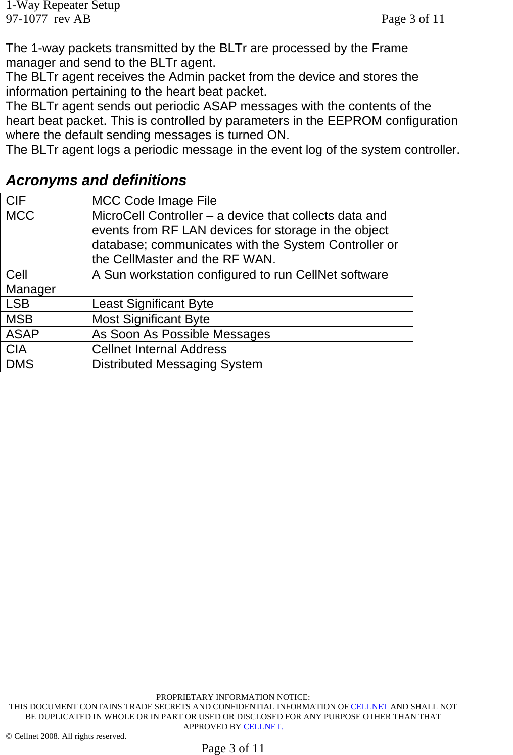
![1-Way Repeater Setup 97-1077 rev AB Page 8 of 11 PROPRIETARY INFORMATION NOTICE: THIS DOCUMENT CONTAINS TRADE SECRETS AND CONFIDENTIAL INFORMATION OF CELLNET AND SHALL NOT BE DUPLICATED IN WHOLE OR IN PART OR USED OR DISCLOSED FOR ANY PURPOSE OTHER THAN THAT APPROVED BY CELLNET. © Cellnet 2008. All rights reserved. Page 8 of 11 MCC860 EEPROM Configuration Menu d Display all configuration items a page at a time x Display all configuration items with no paging D Display only new items s Set specific items (choose from paged list) n Set specific items by name or id number a Interactively set all items (prompt for each one) A Interactively set new items e Interactively set all out-of-range items E Interactively set out-of-range new items r Set all items to defaults (no prompting) R Set new items to defaults f Set all out-of-range items to defaults F Set out-of-range new items to defaults S Save EEPROM cache to NAND File G Get the EEPROM params from Nand q Quit Select option (? for menu): q You have changed parameters which require an MCC Hot Boot. Are you ready to reset? (y/n): y The following comes back up after the MCC resets Cellnet MicroCell Controller 14.0.06_860,[v14035-mcc-p14.17-cmgcs@pagoda],01-17-08@17:05:16 Warm starting all MCC860 tasks... WAST DOGY PCMT PTST SCCT PFMT DIAG RSTP DLTT ODES OTBS CALA TOUA OD1A TOMM MLPA ASAP RFLA RDSA RSTT DTTA RCAT TIME MCCA MCAA OFTT EVST LSTA TOAT STMT PFTT SRAT DTOA BLTR 34 tasks started, recovering ODE database..., 1206038499,12 Reset flag RESET_CONFIG_CHANGE 1206038499,12 [ BANK B ] Reset msg "EEPROM changes require Hot Boot" MCC860 Waiting for Recovery End](https://usermanual.wiki/Landis-Gyr-Technology/CG6R1S1/User-Guide-936965-Page-9.png)