Landis Gyr Technology CGR1S2 BLT5 User Manual 12 0230 Exhibit Cover
Landis+Gyr Technology, Inc. BLT5 12 0230 Exhibit Cover
Manual

5015 B.U. Bowman Drive Buford, GA 30518 USA Voice: 770-831-8048 Fax: 770-831-8598
Certification Exhibit
FCC ID: R7PCGR1S2
FCC Rule Part: 15.247
ACS Project Number: 12-0230
Manufacturer: Landis+Gyr Technology, Inc.
Model: BLT5
Manual

PROPRIETARY INFORMATION NOTICE: THIS DOCUMENT CONTAINS TRADE SECRETS AND CONFIDENTIAL INFORMATION OF LANDIS+GYR AND
SHALL NOT BE DUPLICATED IN WHOLE OR IN PART OR USED OR DISCLOSED FOR ANY PURPOSE OTHER THAN THAT APPROVED BY LANDIS+GYR.
Assembly Instructions, Kit, BLT5
Transceiver, MCC, 97-1828
Revision History
ECO
Revision
Date
Author
Comments
ECO-051889 AA 8/20/2012 Robert Johnson Initial Release
ECO-052962 AB 4/10/2014 Robert Johnson Modifcation to initial Release, added FCC statement

Assembly Instructions, Kit, BLT5, MCC 97-1828 Rev AB Page 2of 4
PROPRIETARY INFORMATION NOTICE: THIS DOCUMENT CONTAINS TRADE SECRETS AND CONFIDENTIAL INFORMATION OF LANDIS+GYR AND
SHALL NOT BE DUPLICATED IN WHOLE OR IN PART OR USED OR DISCLOSED FOR ANY PURPOSE OTHER THAN THAT APPROVED BY LANDIS+GYR.
CONTENTS
1 INTRODUCTION ..................................................................................................................................................................3
2 REMOVING THE EXISTING BLT3 TRANSCEIVER FROM THE MCC’S ENCLOSER...........................................3
3 RE-INSTALLING THE UPDATED LAN/WAN BRACKET ASSEMBLY CONTAINING THE UPDATED
BLT5 TRANSCEIVER UNIT INTO THE MCC ENCLOSER..........................................................................................3
4. FINAL INSTALLATION......................................................................................................................................................4
5. FCC…………………………………………………………………………………………………………………………………………….4

Assembly Instructions, Kit, BLT5, MCC 97-1828 Rev AB Page 3of 4
PROPRIETARY INFORMATION NOTICE: THIS DOCUMENT CONTAINS TRADE SECRETS AND CONFIDENTIAL INFORMATION OF LANDIS+GYR AND
SHALL NOT BE DUPLICATED IN WHOLE OR IN PART OR USED OR DISCLOSED FOR ANY PURPOSE OTHER THAN THAT APPROVED BY LANDIS+GYR.
1 Introduction
1.1 All MCCs updated in the field requiring replacement of their original BLT3 transceiver to the newly
designed BLT5 transceiver must also be retro-fitted per the guidelines specified in this procedure.
The MCC field update consists of removing the original BLT3 transceiver, and replacing it with the
newly redesigned BLT5 transceiver. After the new BLT5 transceiver has been installed you will
also need to install a new FCC label, part number 23-1401. The new FCC label should be placed
on the MCC’s exterior where it will be highly visible. The new FCC, BLT5 Retrofit label can be
found in the MCC retro-fit kit, designated as follows: Kit, BLT5 Transceiver, MCC kit, Landis part
number 45-1828. The bill of materials is listed below.
Kit, BLT5 Transceiver, MCC Part number 45-1828
item_number item_name quantity
23-1127 LABEL,BLANK,UTILITY ID 1
90-1002 BAG, 9"X12"X.004 CLEAR POLY BAG WITH
ZIPPER 2
97-1828 Assembly Instructions, Kit, BLT5 Transceiver, MCC 1
23-1401 Label, FCC, BLT5 Retrofit 1
26-1828 T/A, BLT5 Transceiver, MCC 0
1
1
2. Removing the existing BLT3 transceiver from the MCC’s enclosure
2.1 Refer to Landis document part number : 97-2350, MPI, REPACKAGED ASSEMBLY
INSTRUCTION, section 3.0 through section 3.8 for details on how to remove the exisiting BLT3
transceiver module.
2.2. To remove the existing, original BLT3 transceiver, disconnect the antenna cables P/N: 19-0014,
LAN/WAN Radio Power Cable assembly P/N 19-2351, and the LAN Data cables P/N: 19-2352.
2.3.Losen the LAN/WAN assembly backet’s machine-screw Hex-nuts. The stated Hex-nuts are used
to hold down the LAN/WAN assembly to the inside of the MCC enclosure, then remove the
LAN/WAN assembly from the MCC enclosure. Once the LAN/WAN assembly has been pulled
from the MCC inclosure, losen the hex-nuts used to hold down the original BLT3 transceiver
assembly to the LAN/WAN assembly mouting bracket, pull the BLT3 transciever for the LAN/WAN
mounting bracket assembly, and replace the orignal BLT3 transceiver will the newly redesigned
BLT5 transceiver assembly.
3. Re-installing the updated LAN/WAN bracket assembly containing the
updated BLT5 transceiver unit into the MCC encloser
3.1 Once you have re-fitted the BLT5 transceiver on the LAN/WAN mounting bracket assembly, re-
torque the mounting Hex-nuts used to hold the BLT5 assembly to the LAN/WAN mounting
bracket, then, re-install the LAN/WAN mounting bracket assembly inside the MCC enclosure, and
re-torque the LAN/WAN mounting bracket’s Hex-nuts. The stated Hex-nuts are used to mount the
LAN/WAN bracket assembly down to the inside of the MCC enclosure.
3.2 On completion of re-installing the LAN/WAN bracket assembly containing the newly added BLT5
transceiver you can re-connect the antenna cables P/N: 19-0014, LAN/WAN Radio Power Cable
assembly P/N 19-2351, and the LAN Data cable P/N: 19-2352,
Assembly Instructions, Kit, BLT5, MCC 97-1828 Rev AB Page 4of 4
PROPRIETARY INFORMATION NOTICE: THIS DOCUMENT CONTAINS TRADE SECRETS AND CONFIDENTIAL INFORMATION OF LANDIS+GYR AND
SHALL NOT BE DUPLICATED IN WHOLE OR IN PART OR USED OR DISCLOSED FOR ANY PURPOSE OTHER THAN THAT APPROVED BY LANDIS+GYR.
4. Final Installation
4.1 From your MCC retro fit kit contained in a 9”x 12” zip lock bag, remove the new FCC, BLT5
Retrofit label, part number 23-1401. Next remove the label’s non-stick backing paper to expose
the adhesive side of the lablel then stick the new FCC label on the outside of the MCC’s
enclosure. The label should be placed on the enclosure’s painted exterior bottom where it will be
highly visible.
4.1 The MCC may be returned to service.
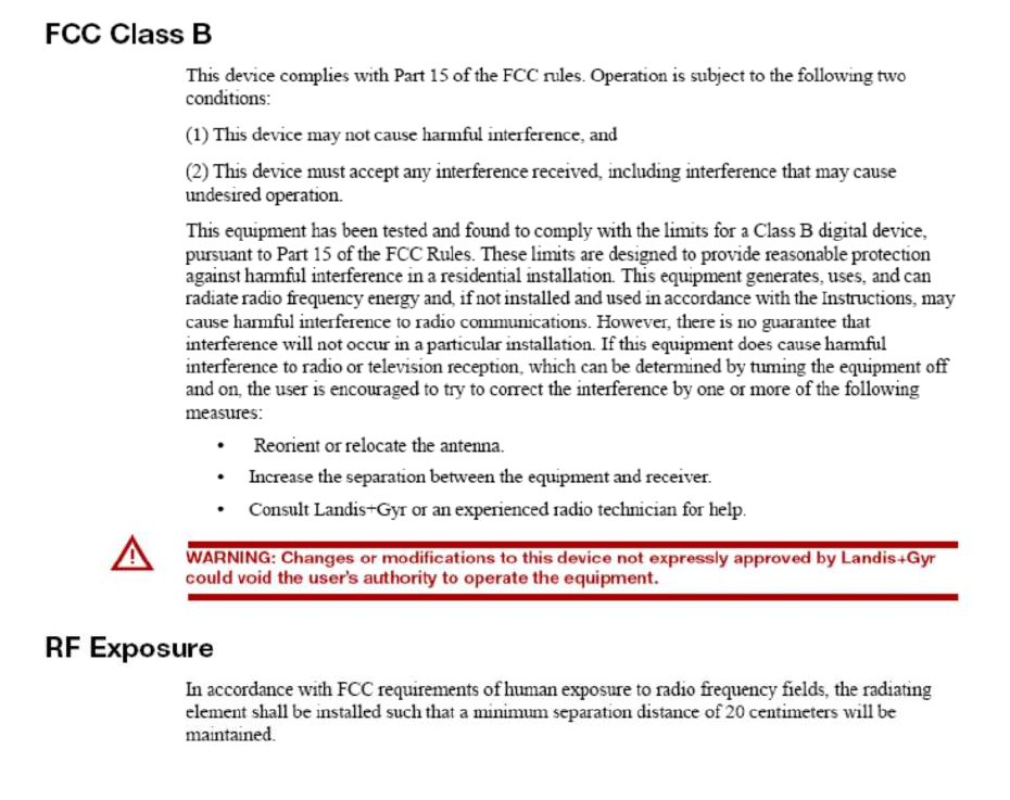
5. FCC
This product shall comply with the FCC requirements listed in United States CFR Title 47, Part 15.109,
15.209 and15.247.
The FCC tests should be performed with the meter module in the configuration s close to the typical
field configuration as possible.