Landis Gyr Technology EC1R1S1 Multi-Function Meter Module User Manual 12 0278 Exhibit Cover
Landis+Gyr Technology, Inc. Multi-Function Meter Module 12 0278 Exhibit Cover
Manual

5015 B.U. Bowman Drive Buford, GA 30518 USA Voice: 770-831-8048 Fax: 770-831-8598
Certification Exhibit
FCC ID: R7PEC1R1S1
FCC Rule Part: 15.247
ACS Project Number: 12-0278
Manufacturer: Landis+Gyr Technology Inc.
Model: Elster Multi-Function Meter Module
Manual

LANDIS+GYR CONFIDENTIAL INFORMATION
Elster Multi-Function
Meter Module
Quick Start Guide
Publication: 98-1289 Rev AA
Draft 8/23/2013

Limitation on Warranties and Liability
Information in this document is subject to change without notice. This manual or any part of it thereof may not be re-
produced in any form unless permitted by contract or by written permission of Landis+Gyr.
In no event will Landis+Gyr be liable for any incidental, indirect, special, or consequential damages (including lost prof-
its) arising out of or relating to this publication or the information contained in it, even if Landis+Gyr has been advised,
knew, or should have known of the possibility of such damages.
Other brands or product names used are the trademarks or registered trademarks of their respective holders.
© 2013 Landis+Gyr, Inc. All Rights Reserved
Elster Multi-Function Meter Module Quick Start Guide
Publication: 98-1289
Revision History
Modification Date Revision Description Author
12/4/2012 AA In Progress Vicky Costello
Landis+Gyr
30000 Mill Creek Avenue, Suite 100
Alpharetta, GA 30022
Website: www.landisgyr.com
E-mail: solutionsupport.na@landisgyr.com
Technical Support: 1-888-390-5733
Copyright© 2013 Landis+Gyr
All rights reserved.
Draft 8/23/2013
Landis+Gyr Confidential Information 98-1289 Rev AA 3
Elster Multi-Function Meter
Module Quick Start Guide
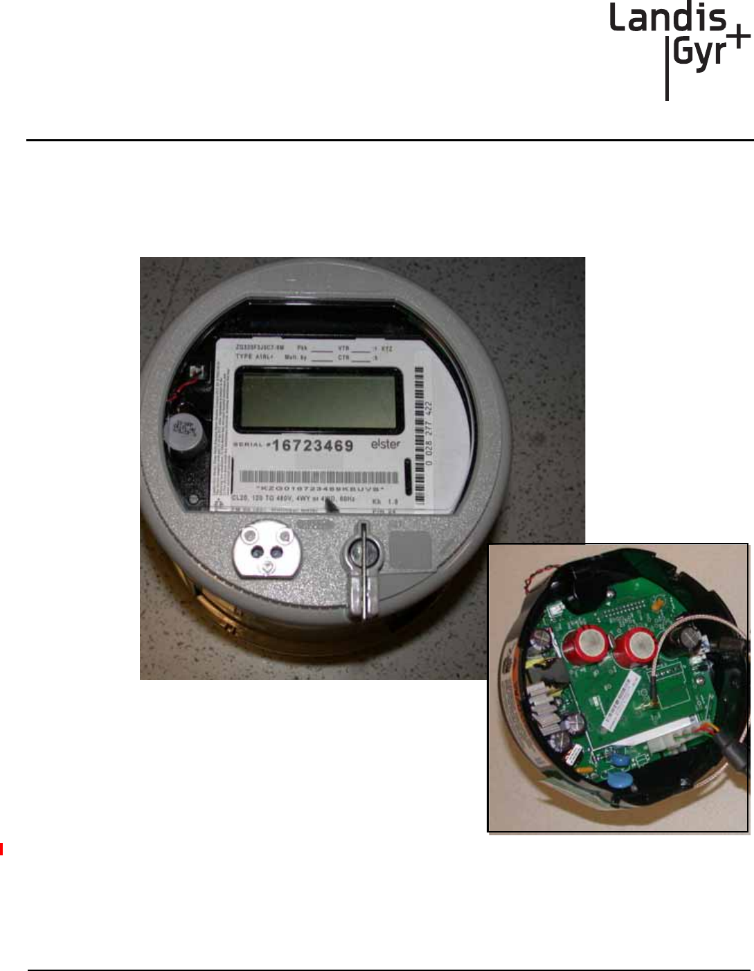
Overview
The Elster Multi-Function Meter Module (MFMM) is designed to provide active energy (Kilo-Watt
hour) and reactive energy (Kilo-Var hour) data from Elster Alpha+ (A2) meters for use in residential
and industrial commercial services.
Figure 1 - 1. Elster Multi-Function Meter Module
The meter kit includes:
•Elster Multi-Function Meter Module
•Elster Alpha+ (A2) Meter
Draft 8/23/2013
Elster Multi-Function Meter Module Quick Start Guide Landis+Gyr
4 98-1289 Rev AA Landis+Gyr Confidential Information
•Antenna
Required Software
To work with the endpoint, you need at least one of the following software tools and documentation:
•UtiliNet Solution Center (USC)
•Meter Master Lite software
•Meter Master Lite Quick Start Guide, publication number 98-0071
•Elster ALPHA Plus software
Landis+Gyr recommends you have RF Verify software and the RF Verify User Guide, publication
number 98-0069.
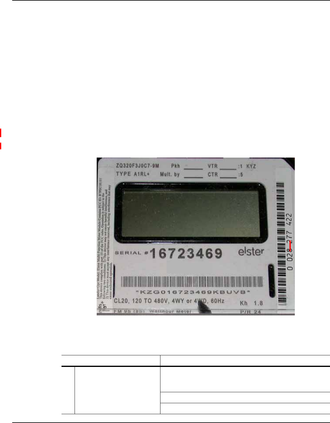
Labels
The endpoint contains the following labels:
Figure 2. Label Identification
Table 1. Elster Label Identification
Label Description
1 Elster Meter Name Plate AEP compliant bar code that defines meter manufacturer, form,
base, test voltage and current, watt-hour constant, serial number,
and customer specific information.
Manufacturer or customer specified serial number
Manufacturer model and style number
1
2
3
Draft 8/23/2013

Landis+Gyr Elster Multi-Function Meter Module Quick Start Guide
Landis+Gyr Confidential Information 98-1289 Rev AA 5
LAN ID
The LAN ID is a unique identifier for each Landis+Gyr endpoint. Landis+Gyr provides the LAN
address. You cannot change the radio’s LAN IDs.
Features and Functions
Endpoint Registration
The endpoint is automatically registered with the host system. No special tools are needed during
installation.
Admin packets are sent once each hour at a random time during the hour and play a crucial role in
the automatic discovery of a meter by the Landis+Gyr system. They tell what kind of meter the
module interfaces with, and other characteristics, such as the scaling constant, number of dials, and
the firmware version.
Admin packets include:
Communication and Retrieving Data
A microprocessor on the communications module (MFMM) reads energy data through the meter’s
serial interface and transmits the information to the head end system. Several different packet types
are sent.The most frequently sent packet contains the current rotational count and historical interval
data that is useful for load profiling and time-of-use metering. Another less frequently sent (Admin)
packet contains the current cumulative rotation count, useful for basic automatic meter reading
applications. An Admin packet is sent once hourly and contains the information listed in Table 2.
2 Landis+Gyr FCC ID Federal Communications Commission (FCC) Identification (ID)
number assigned to the Elster Multi-Function Meter Module for
use in the Elster Alpha+ meter.
3 Landis+Gyr LAN ID Identifies the Elster Multi-Function Meter Module to the
Landis+Gyr billing network (printed and barcoded).
Table 1. Elster Label Identification
Label Description
Table 2. Admin Packet Information
Meter ID Identifies the customer
Protocol ID Identifies the type of meter.
Scaling Constant Tells how to convert meter readings into real units such as kWh
Number of dials Also referred to as displayed digits.
Maximum Sensor Change Rate Tells how much the meter reading can change in a certain period of
time.
Firmware Version Specifies the firmware revision number.
Current Cumulative Reading from the meter
Draft 8/23/2013

Elster Multi-Function Meter Module Quick Start Guide Landis+Gyr
6 98-1289 Rev AA Landis+Gyr Confidential Information
Power Outage/Restoration
The Multi-Function Meter Module gets Power Fail signal from meter. The communication module
saves critical endpoint data to non-volatile memory, creates and sends a configurable number of
power fail messages (typically 20) to the host system that include the LAN ID.
When power is restored, the communication module (MFMM) sends a Power Up message from
Channel 1 and Channel 2, if available, to the host system. This message includes the following
information:
•LAN ID
•Total count
•Last ten interval counts
Customer Service
Contact Landis+Gyr Customer Support at solutionsupport.na@landisgyr.com or call 888-390-5733
with any questions or problems for guidance through the troubleshooting process.
Compliance
FCC Class B
This device complies with Part 15 of the FCC rules. Operation is subject to the following two
conditions:
(1) This device may not cause harmful interference, and
(2) This device must accept any interference received, including interference that may cause
undesired operation.
This equipment has been tested and found to comply with the limits for a Class B digital device,
pursuant to Part 15 of the FCC Rules. These limits are designed to provide reasonable protection
against harmful interference in a residential installation. This equipment generates, uses, and can
radiate radio frequency energy and, if not installed and used in accordance with the Instructions, may
cause harmful interference to radio communications. However, there is no guarantee that
interference will not occur in a particular installation. If this equipment does cause harmful
interference to radio or television reception, which can be determined by turning the equipment off
and on, the user is encouraged to try to correct the interference by one or more of the following
measures:
•Reorient or relocate the antenna.
•Increase the separation between the equipment and receiver.
•Consult Landis+Gyr or an experienced radio technician for help.
UWARNING: Changes or modifications to this device not expressly approved by Landis+Gyr
could void the user’s authority to operate the equipment.
Draft 8/23/2013

Landis+Gyr Elster Multi-Function Meter Module Quick Start Guide
Landis+Gyr Confidential Information 98-1289 Rev AA 7
RF Exposure
In accordance with FCC requirements of human exposure to radio frequency fields, the radiating
element shall be installed such that a minimum separation distance of 20 centimeters will be
maintained.
Host FCC Label Requirement
In the final installation, the following information must be visible:
“Contains FCC ID: R7PEC1R1S1
This device complies with Part 15 of the FCC rules. Operation is subject to the following two
conditions:
(1) This device may not cause harmful interference, and
(2) This device must accept any interference received, including interference that may cause
undesired operation.”
Draft 8/23/2013
Elster Multi-Function Meter Module Quick Start Guide Landis+Gyr
8 98-1289 Rev AA Landis+Gyr Confidential Information
Product Specifications
Table 3. Elster Multi-Function Meter Module Specifications
Category Specification Value or Range
Compatible
Meters
Elster ALPHA Plus Supported
Meter Forms
NOTE: Contact Elster
Electricity for
additional forms.
Form Class
1S 200
1S 320
2S 200
2S 320
3S 20
4S 20
35S 20
35A 20
12S 200
12S 320
13S 200
13S 320
13A 100
36S 20
36A 20
9S 20
10S 20
10A 20
16S 200
16S 320
16A 100
Electrical
Voltage
13.5VDC + 1V, 50mA (limited
duration from meter’s power
supply)
Input Current 50mA
RF
Output Power 22-26.5 dBm
Transmit Frequency 917.58 MHz (Fixed))
Draft 8/23/2013

Landis+Gyr Elster Multi-Function Meter Module Quick Start Guide
Landis+Gyr Confidential Information 98-1289 Rev AA 9
Standards
Compliance
FCC Title 47 CFR Part 15
Subpart B & C
Radiated and Conducted
Emissions
IEC 61000 4-2,3,4,5 Electromagnetic Compatibility
ANSI C12.1-2011 Electricity Metering
ANSI C12.20-2002 Electricity Meters Standard
ANSI C37.90.1
Substation Standards - Fast
Transient and Oscillatory
Waveform
ANSI/IPC-A-610-Class 2 Workmanship Standard for
Electronic Assemblies
Environmental
General Environmental Outdoor, rain-protected,
sunlight-exposed
Operating Temperature Range -40 to +85 C (under meter
glass)
Humidity 10% to 95% relative humidity,
non-condensing
Mechanical
Size (Meter & Module)
Refer to Elster Technical
Manual, TM42-2182E for more
details.
Weight (Meter & Module)
Refer to Elster Technical
Manual, TM42-2182E for more
details.
Table 3. Elster Multi-Function Meter Module Specifications
Category Specification Value or Range
Draft 8/23/2013
Elster Multi-Function Meter Module Quick Start Guide Landis+Gyr
10 98-1289 Rev AA Landis+Gyr Confidential Information
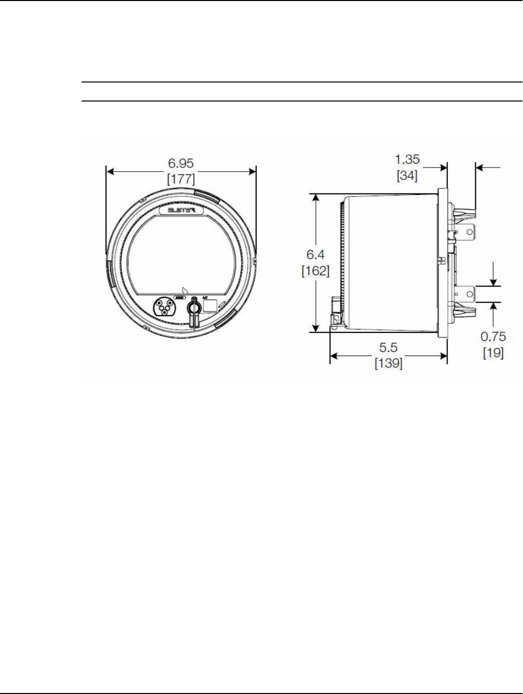
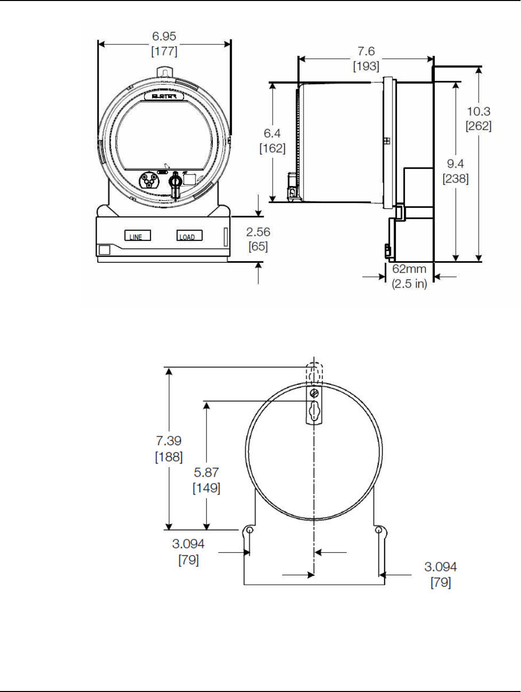
Physical Dimensions
The ALPHA Plus meter fits all standard S-base services. Meters with an A-base are also available.
Figure 1 - 1 illustrates the S-base meter type and dimensions.
NOTE: The dimensions are for reference purposes only and should not be used for construction.
Figure 1 - 1. S-base Meter Type and Dimensions in Inches (millimeters) - Front and Side View
Figure 1 - 2 and Figure 1 - 3 illustrate the A-base meter type and dimensions.
Draft 8/23/2013
Landis+Gyr Elster Multi-Function Meter Module Quick Start Guide
Landis+Gyr Confidential Information 98-1289 Rev AA 11
Figure 1 - 2. A-base Meter Type and Dimensions in Inches (millimeters) - Front and Side View
Figure 1 - 3. A-base Meter Type and Dimensions in Inches (millimeters) - Back View
Draft 8/23/2013

Elster Multi-Function Meter Module Quick Start Guide Landis+Gyr
12 98-1289 Rev AA Landis+Gyr Confidential Information
Draft 8/23/2013