Landis Gyr Technology EC6R1S3 2-way Gas Module User Manual 14 0364 Exhibit Cover
Landis+Gyr Technology, Inc. 2-way Gas Module 14 0364 Exhibit Cover
Manual

5015 B.U. Bowman Drive Buford, GA 30518 USA Voice: 770-831-8048 Fax: 770-831-8598
Certification Exhibit
FCC ID: R7PEC6R1S3
IC: 5294A-EC6R1S3
FCC Rule Part: 15.247
IC Radio Standards Specification: RSS-210
ACS Project Number: 14-0364
Manufacturer: Landis+Gyr Technology, Inc.
Model: GPR2

LANDIS+GYR CONFIDENTIAL INFORMATION
GPR Installation Guide
Publication: 98-1135 Rev AB

Limitation on Warranties and Liability
Information in this document is subject to change without notice. This manual or any part of it thereof may not be re-
produced in any form unless permitted by contract or by written permission of Landis+Gyr.
In no event will Landis+Gyr be liable for any incidental, indirect, special, or consequential damages (including lost prof-
its) arising out of or relating to this publication or the information contained in it, even if Landis+Gyr has been advised,
knew, or should have known of the possibility of such damages.
© 2014 Landis+Gyr, Inc. All Rights Reserved
GPR Installation Guide
Publication: 98-1135
Revision History
Modification Date Revision Description Author
01/27/2014 AA Pre-Release Draft Charlie Goerges
02/20/2014 AA Review Jake Harsha
06/19/2014 AA Released Charlie Goerges
10/27/2014 AB
Updated Dresser Roots dial
wheel installation; index
cover part numbers
Jake Harsha
Landis+Gyr
Website: www.landisgyr.com
E-mail: solutionsupport.na@landisgyr.com
Technical Support: 1-888-390-5733
© 2014 Landis+Gyr
All rights reserved.

Installation Guide 98-1135 Rev AA 3
Table of Contents
Chapter 1: Pre-Installation . . . . . . . . . . . . . . . . . . . . . . . . . . . . . . . . . . . . . . . . . . . . . . . . . . . . . . . . . . . 7
Before You Begin . . . . . . . . . . . . . . . . . . . . . . . . . . . . . . . . . . . . . . . . . . . . . . . . . . . . . . . . . . . . . . . . . . . . . . . . 7
Safety Overview . . . . . . . . . . . . . . . . . . . . . . . . . . . . . . . . . . . . . . . . . . . . . . . . . . . . . . . . . . . . . . . . . . . . . . . . . 7
FCC & Industry Canada Information to the User. . . . . . . . . . . . . . . . . . . . . . . . . . . . . . . . . . . . . . . . . 8
FCC Class B. . . . . . . . . . . . . . . . . . . . . . . . . . . . . . . . . . . . . . . . . . . . . . . . . . . . . . . . . . . . . . . 8
RF Exposure . . . . . . . . . . . . . . . . . . . . . . . . . . . . . . . . . . . . . . . . . . . . . . . . . . . . . . . . . . . . . . 8
Industry Canada . . . . . . . . . . . . . . . . . . . . . . . . . . . . . . . . . . . . . . . . . . . . . . . . . . . . . . . . . . . . 9
Compliance . . . . . . . . . . . . . . . . . . . . . . . . . . . . . . . . . . . . . . . . . . . . . . . . . . . . . . . . . . . . . . . . . . . . . . 9
Preliminary Checks . . . . . . . . . . . . . . . . . . . . . . . . . . . . . . . . . . . . . . . . . . . . . . . . . . . . . . . . . . . . . . . . 9
Site Requirements . . . . . . . . . . . . . . . . . . . . . . . . . . . . . . . . . . . . . . . . . . . . . . . . . . . . . . . . . . . . . . . . . 9
Required Installation Tools . . . . . . . . . . . . . . . . . . . . . . . . . . . . . . . . . . . . . . . . . . . . . . . . . . . . . . . . . 10
Required Parts . . . . . . . . . . . . . . . . . . . . . . . . . . . . . . . . . . . . . . . . . . . . . . . . . . . . . . . . . . . . . . . . . . . . . . . . . . 10
American Meters Required Materials . . . . . . . . . . . . . . . . . . . . . . . . . . . . . . . . . . . . . . . . . . . . . . . . . 11
Index Cover Kits . . . . . . . . . . . . . . . . . . . . . . . . . . . . . . . . . . . . . . . . . . . . . . . . . . . . . . . . . . 11
Dial Wheels . . . . . . . . . . . . . . . . . . . . . . . . . . . . . . . . . . . . . . . . . . . . . . . . . . . . . . . . . . . . . . 11
GPR + Brackets Kits . . . . . . . . . . . . . . . . . . . . . . . . . . . . . . . . . . . . . . . . . . . . . . . . . . . . . . . 12
Rockwell Meters Required Materials . . . . . . . . . . . . . . . . . . . . . . . . . . . . . . . . . . . . . . . . . . . . . . . . . 15
Index Cover Kit . . . . . . . . . . . . . . . . . . . . . . . . . . . . . . . . . . . . . . . . . . . . . . . . . . . . . . . . . . . 15
Dial Wheel . . . . . . . . . . . . . . . . . . . . . . . . . . . . . . . . . . . . . . . . . . . . . . . . . . . . . . . . . . . . . . . 15
GPR + Brackets Kit . . . . . . . . . . . . . . . . . . . . . . . . . . . . . . . . . . . . . . . . . . . . . . . . . . . . . . . . 15
Schlumberger Meters Required Materials . . . . . . . . . . . . . . . . . . . . . . . . . . . . . . . . . . . . . . . . . . . . . .17
Index Cover Kit . . . . . . . . . . . . . . . . . . . . . . . . . . . . . . . . . . . . . . . . . . . . . . . . . . . . . . . . . . . 17
Dial Wheel . . . . . . . . . . . . . . . . . . . . . . . . . . . . . . . . . . . . . . . . . . . . . . . . . . . . . . . . . . . . . . . 17
GPR + Brackets Kit . . . . . . . . . . . . . . . . . . . . . . . . . . . . . . . . . . . . . . . . . . . . . . . . . . . . . . . . 18
Sprague Meters Required Materials . . . . . . . . . . . . . . . . . . . . . . . . . . . . . . . . . . . . . . . . . . . . . . . . . . . 19
Index Cover Kit . . . . . . . . . . . . . . . . . . . . . . . . . . . . . . . . . . . . . . . . . . . . . . . . . . . . . . . . . . . 20
Dial Wheel . . . . . . . . . . . . . . . . . . . . . . . . . . . . . . . . . . . . . . . . . . . . . . . . . . . . . . . . . . . . . . . 20
GPR + Brackets Kit . . . . . . . . . . . . . . . . . . . . . . . . . . . . . . . . . . . . . . . . . . . . . . . . . . . . . . . . 21
Rotary Required Materials . . . . . . . . . . . . . . . . . . . . . . . . . . . . . . . . . . . . . . . . . . . . . . . . . . . . . . . . . . 23
Cable . . . . . . . . . . . . . . . . . . . . . . . . . . . . . . . . . . . . . . . . . . . . . . . . . . . . . . . . . . . . . . . . . . . 23
GPR+ Brackets Kit . . . . . . . . . . . . . . . . . . . . . . . . . . . . . . . . . . . . . . . . . . . . . . . . . . . . . . . . 23
Dresser Roots Required Materials . . . . . . . . . . . . . . . . . . . . . . . . . . . . . . . . . . . . . . . . . . . . . . . . . . . . 24
Meter Adapter Kit (ordered from GE). . . . . . . . . . . . . . . . . . . . . . . . . . . . . . . . . . . . . . . . . . 24
Gridstream Module . . . . . . . . . . . . . . . . . . . . . . . . . . . . . . . . . . . . . . . . . . . . . . . . . . . . . . . . 24
Index . . . . . . . . . . . . . . . . . . . . . . . . . . . . . . . . . . . . . . . . . . . . . . . . . . . . . . . . . . . . . . . . . . . 24
Chapter 2: Index Cover Pulser Install and Operation Start Up . . . . . . . . . . . . . . . . . . . . . . . . . . . . . . . 25
Introduction . . . . . . . . . . . . . . . . . . . . . . . . . . . . . . . . . . . . . . . . . . . . . . . . . . . . . . . . . . . . . . . . . . . . . . . . . . . . 25
Interface to a Single Form-C Volume Output . . . . . . . . . . . . . . . . . . . . . . . . . . . . . . . . . . . . . . . . . . .26
Start the GPR Operation In Install Mode . . . . . . . . . . . . . . . . . . . . . . . . . . . . . . . . . . . . . . . . . . . . . . . . . . . . . 28
Chapter 3: American GPR Index Cover & GPR Install . . . . . . . . . . . . . . . . . . . . . . . . . . . . . . . . . . . . . . 31
American Index Cover & and Gas Module Removal . . . . . . . . . . . . . . . . . . . . . . . . . . . . . . . . . . . . . . . . . . . . 31
Meter Preparation . . . . . . . . . . . . . . . . . . . . . . . . . . . . . . . . . . . . . . . . . . . . . . . . . . . . . . . . . . . . . . . . . 31
American Mini Switch Kit Installation . . . . . . . . . . . . . . . . . . . . . . . . . . . . . . . . . . . . . . . . . . . . . . . . . . . . . . . 33

Table of Contents Landis+Gyr
4 98-1135 Rev AA Installation Guide
Meter Preparation . . . . . . . . . . . . . . . . . . . . . . . . . . . . . . . . . . . . . . . . . . . . . . . . . . . . . . . . . . . . . . . . .33
Installing Index Face Mount Dial Wheels on Metal Pointer Indexes . . . . . . . . . . . . . . . . . . 35
Installing Balanced Dial Wheels on Plastic Pointer Indexes . . . . . . . . . . . . . . . . . . . . . . . . . 37
GPR Direction . . . . . . . . . . . . . . . . . . . . . . . . . . . . . . . . . . . . . . . . . . . . . . . . . . . . . . . . . . . . . . . . . . . . . . . . . .41
GPR Mounting . . . . . . . . . . . . . . . . . . . . . . . . . . . . . . . . . . . . . . . . . . . . . . . . . . . . . . . . . . . . . . . . . . . . . . . . . .42
American Changing GPR Orientation . . . . . . . . . . . . . . . . . . . . . . . . . . . . . . . . . . . . . . . . . . . . . . . . . . . . . . . .43
Chapter 4: Rockwell GPR Index Cover & GPR Install . . . . . . . . . . . . . . . . . . . . . . . . . . . . . . . . . . . . . . .47
Rockwell Index Cover & Gas Module Removal . . . . . . . . . . . . . . . . . . . . . . . . . . . . . . . . . . . . . . . . . . . . . . . .47
Meter Preparation . . . . . . . . . . . . . . . . . . . . . . . . . . . . . . . . . . . . . . . . . . . . . . . . . . . . . . . . . . . . . . . . .47
Rockwell Mini Switch Kit Installation . . . . . . . . . . . . . . . . . . . . . . . . . . . . . . . . . . . . . . . . . . . . . . . . . . . . . . .49
Meter Preparation . . . . . . . . . . . . . . . . . . . . . . . . . . . . . . . . . . . . . . . . . . . . . . . . . . . . . . . . . . . . . . . . .49
Installing Back Mount Dial Wheels . . . . . . . . . . . . . . . . . . . . . . . . . . . . . . . . . . . . . . . . . . . . 50
Installing the Index . . . . . . . . . . . . . . . . . . . . . . . . . . . . . . . . . . . . . . . . . . . . . . . . . . . . . . . . . . . . . . . .51
GPR Direction . . . . . . . . . . . . . . . . . . . . . . . . . . . . . . . . . . . . . . . . . . . . . . . . . . . . . . . . . . . . . . . . . . . . . . . . . .53
GPR Mounting . . . . . . . . . . . . . . . . . . . . . . . . . . . . . . . . . . . . . . . . . . . . . . . . . . . . . . . . . . . . . . . . . . . . . . . . . .53
Rockwell Changing GPR Orientation . . . . . . . . . . . . . . . . . . . . . . . . . . . . . . . . . . . . . . . . . . . . . . . . . . . . . . . .55
Chapter 5: Schlumberger GPR Index Cover & GPR Install . . . . . . . . . . . . . . . . . . . . . . . . . . . . . . . . . . .57
Schlumberger Index Cover & Gas Module Removal . . . . . . . . . . . . . . . . . . . . . . . . . . . . . . . . . . . . . . . . . . . .57
Meter Preparation . . . . . . . . . . . . . . . . . . . . . . . . . . . . . . . . . . . . . . . . . . . . . . . . . . . . . . . . . . . . . . . . .57
Index Mounting Bracket Types . . . . . . . . . . . . . . . . . . . . . . . . . . . . . . . . . . . . . . . . . . . . . . . 58
Schlumberger Mini Switch Kit Installation . . . . . . . . . . . . . . . . . . . . . . . . . . . . . . . . . . . . . . . . . . . . . . . . . . . .60
Meter Preparation . . . . . . . . . . . . . . . . . . . . . . . . . . . . . . . . . . . . . . . . . . . . . . . . . . . . . . . . . . . . . . . . .60
Installing Back Mount Dial Wheels . . . . . . . . . . . . . . . . . . . . . . . . . . . . . . . . . . . . . . . . . . . . 61
GPR Direction . . . . . . . . . . . . . . . . . . . . . . . . . . . . . . . . . . . . . . . . . . . . . . . . . . . . . . . . . . . . . . . . . . . . . . . . . .64
GPR Mounting . . . . . . . . . . . . . . . . . . . . . . . . . . . . . . . . . . . . . . . . . . . . . . . . . . . . . . . . . . . . . . . . . . . . . . . . . .64
Schlumberger Changing GPR Orientation . . . . . . . . . . . . . . . . . . . . . . . . . . . . . . . . . . . . . . . . . . . . . . . . . . . .66
Chapter 6: Sprague GPR Index Cover & GPR Install . . . . . . . . . . . . . . . . . . . . . . . . . . . . . . . . . . . . . . .69
Sprague Index Cover & Gas Module Removal . . . . . . . . . . . . . . . . . . . . . . . . . . . . . . . . . . . . . . . . . . . . . . . . .69
Meter Preparation . . . . . . . . . . . . . . . . . . . . . . . . . . . . . . . . . . . . . . . . . . . . . . . . . . . . . . . . . . . . . . . . .69
Sprague Mini Switch Kit Installation . . . . . . . . . . . . . . . . . . . . . . . . . . . . . . . . . . . . . . . . . . . . . . . . . . . . . . . .71
Installing Front Mount Dial Wheels on Metal Pointer Indexes . . . . . . . . . . . . . . . . . . . . . . . . . . . . . .71
Installing Balanced Dial Wheels on Plastic Pointer Indexes . . . . . . . . . . . . . . . . . . . . . . . . . . . . . . . .74
GPR Direction . . . . . . . . . . . . . . . . . . . . . . . . . . . . . . . . . . . . . . . . . . . . . . . . . . . . . . . . . . . . . . . . . . . . . . . . . .76
GPR Mounting . . . . . . . . . . . . . . . . . . . . . . . . . . . . . . . . . . . . . . . . . . . . . . . . . . . . . . . . . . . . . . . . . . . . . . . . . .76
Sprague Changing GPR Orientation . . . . . . . . . . . . . . . . . . . . . . . . . . . . . . . . . . . . . . . . . . . . . . . . . . . . . . . . .80
Chapter 7: Electronic Pulser Installation . . . . . . . . . . . . . . . . . . . . . . . . . . . . . . . . . . . . . . . . . . . . . . . .85
GPR Mounting . . . . . . . . . . . . . . . . . . . . . . . . . . . . . . . . . . . . . . . . . . . . . . . . . . . . . . . . . . . . . . . . . . . . . . . . . .85
Installation Instructions for Outdoor Meters . . . . . . . . . . . . . . . . . . . . . . . . . . . . . . . . . . . . . . . . . . . .85
Electronic Pulser Installation . . . . . . . . . . . . . . . . . . . . . . . . . . . . . . . . . . . . . . . . . . . . . . . . . . . . . . . . . . . . . . .88
GPR Telemetry Specifications . . . . . . . . . . . . . . . . . . . . . . . . . . . . . . . . . . . . . . . . . . . . . . . . . . . . . . .89
Interface to a Single Form-A Volume Output . . . . . . . . . . . . . . . . . . . . . . . . . . . . . . . . . . . . . . . . . . .91
Interface to Mil-Spec Circular Connector . . . . . . . . . . . . . . . . . . . . . . . . . . . . . . . . . . . . . . . . . . . . . .93
Interface to Multi-Outputs . . . . . . . . . . . . . . . . . . . . . . . . . . . . . . . . . . . . . . . . . . . . . . . . . . . . . . . . . .95
Start the GPR Operation In Install Mode . . . . . . . . . . . . . . . . . . . . . . . . . . . . . . . . . . . . . . . . . . . . . . . . . . . . .97

Landis+Gyr Table of Contents
Installation Guide 98-1135 Rev AA 5
Chapter 8: Dresser Roots Installation . . . . . . . . . . . . . . . . . . . . . . . . . . . . . . . . . . . . . . . . . . . . . . . . . . 99
Meter Module Retrofit . . . . . . . . . . . . . . . . . . . . . . . . . . . . . . . . . . . . . . . . . . . . . . . . . . . . . . . . . . . . . . . . . . . 99
Validated Meter Index Part Numbers . . . . . . . . . . . . . . . . . . . . . . . . . . . . . . . . . . . . . . . . . . . . . . . . . . . . . . . 100
Dial Wheel Installation . . . . . . . . . . . . . . . . . . . . . . . . . . . . . . . . . . . . . . . . . . . . . . . . . . . . . . . . . . . . . . . . . . 101
Dial Wheel Installation Cautions . . . . . . . . . . . . . . . . . . . . . . . . . . . . . . . . . . . . . . . . . . . . . . . . . . . . . . . . . . 104
Installing the Module . . . . . . . . . . . . . . . . . . . . . . . . . . . . . . . . . . . . . . . . . . . . . . . . . . . . . . . . . . . . . . . . . . . 104
Operation Startup . . . . . . . . . . . . . . . . . . . . . . . . . . . . . . . . . . . . . . . . . . . . . . . . . . . . . . . . . . . . . . . . . . . . . . 106
Field Programming and Data Collection . . . . . . . . . . . . . . . . . . . . . . . . . . . . . . . . . . . . . . . . . . . . . . . . . . . . . 107
Battery Change Out . . . . . . . . . . . . . . . . . . . . . . . . . . . . . . . . . . . . . . . . . . . . . . . . . . . . . . . . . . . . . . . . . . . . . 107
To Change Out The Battery . . . . . . . . . . . . . . . . . . . . . . . . . . . . . . . . . . . . . . . . . . . . . . . . . . . . . . . 107
Connecting the Battery . . . . . . . . . . . . . . . . . . . . . . . . . . . . . . . . . . . . . . . . . . . . . . . . . . . . 108
Applying Water Sealant to Circuit Board Connections. . . . . . . . . . . . . . . . . . . . . . . . . . . . 109
Ordering Information . . . . . . . . . . . . . . . . . . . . . . . . . . . . . . . . . . . . . . . . . . . . . . . . . . . . . . . . . . . . . . . . . . . 111
Appendix A: GPR Waterproofing . . . . . . . . . . . . . . . . . . . . . . . . . . . . . . . . . . . . . . . . . . . . . . . . . . . . . 113
Applying Water Sealant to Circuit Board Connections . . . . . . . . . . . . . . . . . . . . . . . . . . . . . . . . . . . . . . . . . 113
Ordering Information . . . . . . . . . . . . . . . . . . . . . . . . . . . . . . . . . . . . . . . . . . . . . . . . . . . . . . . . . . . . . . . . . . . 118
Appendix B: Installation in Hazardous
Locations . . . . . . . . . . . . . . . . . . . . . . . . . . . . . . . . . . . . . . . . . . . . . . . . . . . . . . . . . . . . . . . . . . . . . . . 121
Information . . . . . . . . . . . . . . . . . . . . . . . . . . . . . . . . . . . . . . . . . . . . . . . . . . . . . . . . . . . . . . . . . . . . . . . . . . . 121
Control Drawing 86-1006 . . . . . . . . . . . . . . . . . . . . . . . . . . . . . . . . . . . . . . . . . . . . . . . . . . . . . . . . . . . . . . . . 123
Blank Page
1
Installation Guide 98-1135 Rev AB 7
Pre-Installation
Before You Begin
This text contains the symbols which are explained below.
NOTE: Notes provide important information about products and installation.
ACAUTION: Cautions provide information that you must read to avoid making relatively
moderate errors.
UWARNING: Warnings provide special, must-read information. If you ignore a warning you may
create a safety hazard, omit essential data, or make a critical error.
Safety Overview
NOTE: Proper planning and thorough preparation are critical for successful installation. This
chapter outlines basic requirements for the pre-installation phase.
Prior to starting the installation process, you must develop and launch an installer safety training
plan for initial, refresher, and ongoing safety training. Ensure that installers receive appropriate
initial and refresher training to meet their specific safety-related responsibilities. Installers should be
instructed in the following safety elements as well as any site-specific safety issues.
•New duties for which the installer has not previously received training.
•New processes and methodologies representing new risks that are introduced into the
installation environment.
•Situations where previously unidentified risks are reported.
•Hazard Communication (Employee Right to Know)
•Lifting
•Safe driving
•Use of hand tools
•Confined space
The installation supervisory team assumes responsibility for ensuring that installers are properly
trained, authorized, and continually qualified to perform their work. The team must also take
responsibility for the safety of their installers and to assure safe work methodologies. Installers must

Chapter 1 - Pre-Installation Landis+Gyr
8 98-1135 Rev AB Installation Guide
understand that their supervisor’s responsibility does not relieve them from their individual
responsibility to perform the work safely and to follow all safety rules and procedures applicable to
their work.
FCC & Industry Canada Information to the User
Manufacturer: Landis+Gyr
Model Name: American Large Diaphragm GPR
FCC ID: R7PEC6R1S3
IC: 5294A- EC6R1S3
Module Model: GPR2
This device complies with Part 15 of the FCC rules. Operation is subject to the following two
conditions:
1. This device may not cause harmful interference, and
2. This device must accept any interference received, including interference that may cause
undesired operation.
FCC Class B
This equipment has been tested and found to comply with the limits for a Class B digital device,
pursuant to Part 15 of the FCC Rules. These limits are designed to provide reasonable protection
against harmful interference in a residential installation. This equipment generates, uses, and can
radiate radio frequency energy and, if not installed and used in accordance with the Instructions, may
cause harmful interference to radio communications. However, there is no guarantee that
interference will not occur in a particular installation. If this equipment does cause harmful
interference to radio or television reception, which can be determined by turning the equipment off
and on, the user is encouraged to try to correct the interference by one or more of the following
measures:
1. Reorient or relocate the receiving antenna.
2. Increase the separation between the equipment and receiver.
3. Consult Landis+Gyr or an experienced radio technician for help.
UWARNING: Changes or modifications to this device not expressly approved by Landis+Gyr
could void the user's authority to operate the equipment and the product warranty.
RF Exposure
This equipment complies with FCC radiation exposure limits set forth for an uncontrolled
environment. This equipment should be installed and operated with minimum distance 20 cm
between the radiator and your body. This transmitter must not be co-located or operating in
conjunction with any other antenna or transmitter.

Landis+Gyr Chapter 1 - Pre-Installation
Installation Guide 98-1135 Rev AB 9
Industry Canada
This device complies with Industry Canada license-exempt RSS standard(s). Operation is subject to
the following two conditions: (1) this device may not cause interference, and (2) this device must
accept any interference, including interference that may cause undesired operation of the device.
Le présent appareil est conforme aux CNR d'Industrie Canada applicables aux appareils
radiovexempts de licence. L'exploitation est autorisée aux deux conditions suivantes: (1) l'appareil
ne doitvpas produire de brouillage, et (2) l'utilisateur de l'appareil doit accepter tout brouillage
radioélectrique subi, même si le brouillage est susceptible d'en compromettre le fonctionnement.
Under Industry Canada regulations, this radio transmitter may only operate using an antenna of a
type and maximum (or lesser) gain approved for the transmitter by Industry Canada. To reduce
potential radio interference to other users, the antenna type and its gain should be so chosen that the
equivalent isotropically radiated power (e.i.r.p.) is not more than that necessary for successful
communication.
Conformément à la réglementation d'Industrie Canada, le présent émetteur radio peut fonctionner
avec une antenne d'un type et d'un gain maximal (ou inférieur) approuvé pour l'émetteur par
Industrie Canada. Dans le but de réduire les risques de brouillage radioélectrique à l'intention des
autres utilisateurs, il faut choisir le type d'antenne et son gain de sorte que la puissance isotrope
rayonnée équivalente (p.i.r.e.) ne dépasse pas l'intensité nécessaire à l'établissement d'une
communication satisfaisante.
Compliance
This apparatus is suitable for Class I, Division 1, Group D Hazardous Locations.
UWARNING: Substitution of components may impair the suitability for Class I, Division 1
applications. Replace battery only with Landis+Gyr part number 40-1235.
Substitution of components may impair intrinsic safety. Please refer to the notes in Appendix B and
to"Control Drawing 86-1006" on page -123 for connecting to this intrinsically safe device.
Preliminary Checks
1. The installer will verify correct site, as specified on work order.
2. The installer will verify that the site is safe for installer activity and equipment.
3. The installer will notify the customer of installer presence and activity, telling the customer that
meter access is required. If necessary, the installer will have the customer sign the work order.
4. When installing meters, the installer will follow guidelines issued by the utility in addition to
those given in this guide.
5. The installer will never perform an installation during a lightning storm or under excessively wet
conditions.
Site Requirements
The site must comply with the following criteria:
1. There is no chance that another object will be set over the antenna.
Chapter 1 - Pre-Installation Landis+Gyr
10 98-1135 Rev AB Installation Guide
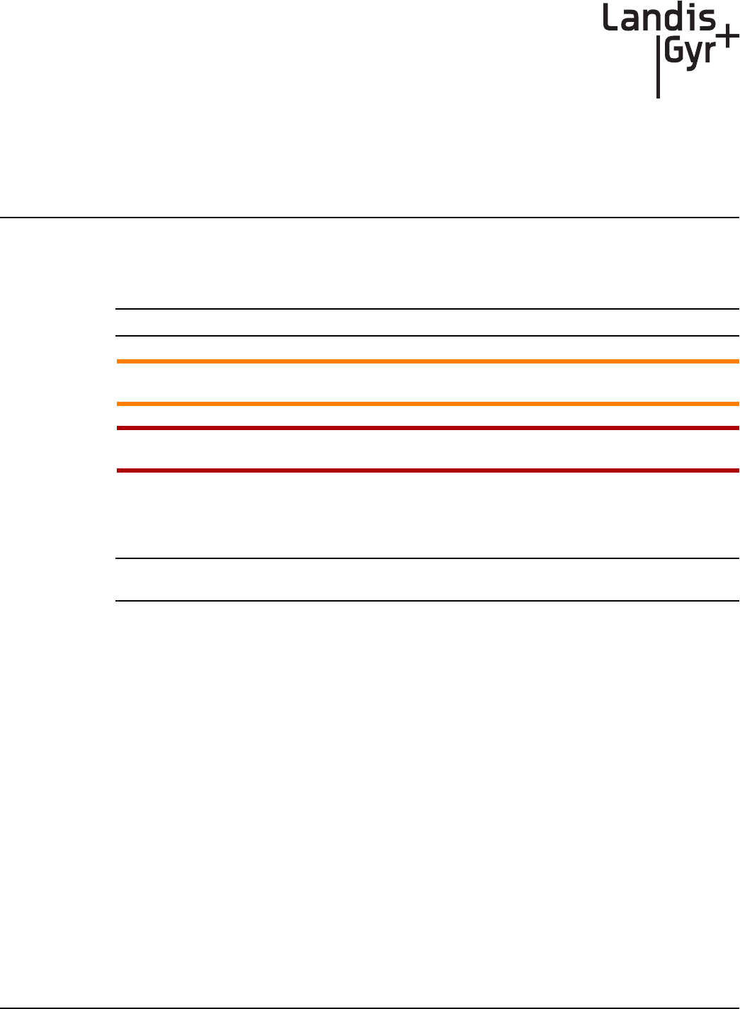
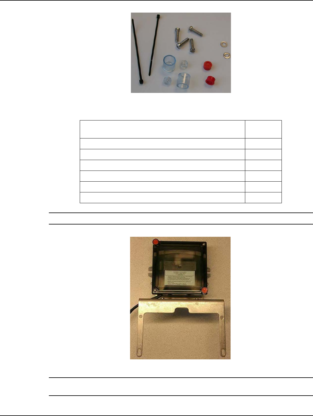
Required Installation Tools
Figure 1 - 1. Examples of some required tools
Recommended Torque Driver Source:
Mountz
1080 N. 11th St. San Jose, CA 95112
Phone: 877-833-1704 or 408-292-2214
Fax: 408-292-2733
e-mail: sales@mountztorque.com
Required Parts
For diaphragm meters an index cover kit, dial wheel, and GPR brackets kit are needed.
Table 1-1. Typical Gas Meter Module Installation Tool List
Torx Pin Head Driver, T10 Phillips Screwdriver, #2
Flat-tip Screwdriver, 3/16 inch x 4 inch Flat-tip Screwdriver, 1/4 inch x 5 inch
Phillips Screwdriver, #0, precision Torque Driver / Wrench, 0.5 inch-
pounds to 20 foot-pounds
Torx Pin Head Driver, T15 5/16 Combination Wrench
Wire Brush Awl, Heavy duty
Scraper, Brass, 1.25 inch wide
Landis+Gyr Chapter 1 - Pre-Installation
Installation Guide 98-1135 Rev AB 11
American Meters Required Materials
Index Cover Kits
Select one based on index type or meter size.
Dial Wheels
Select one wheel based on index type.
NOTE: Shim 29-1300 can be reused in multiple installations.
ACAUTION: Part numbers are subject to change. Contact the Landis+Gyr Supply Chain for the
latest part numbers.
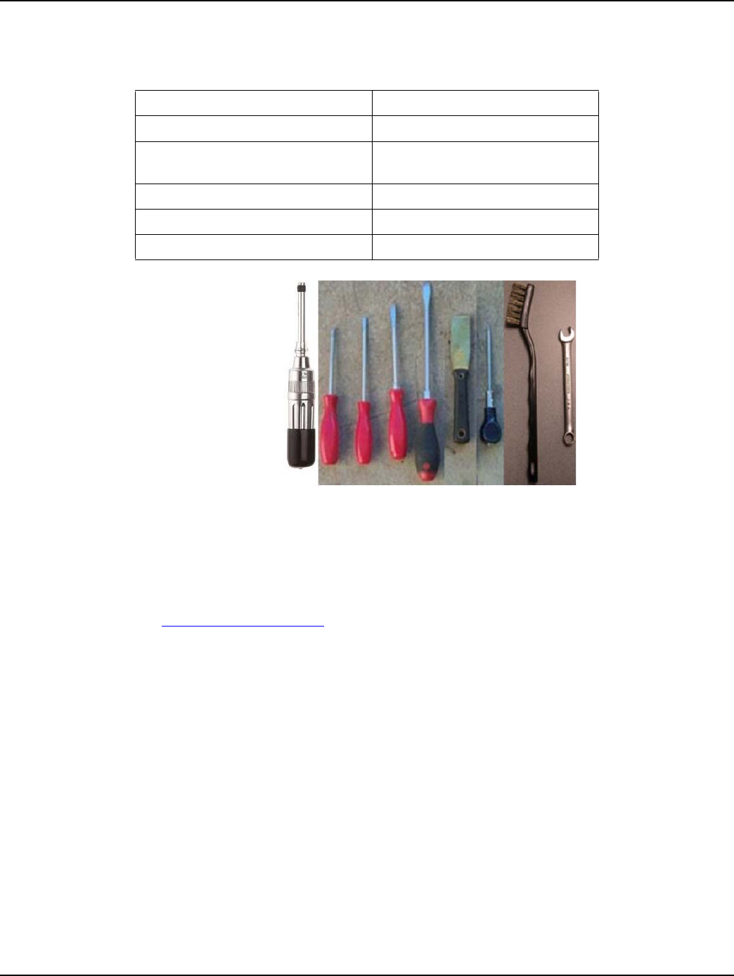
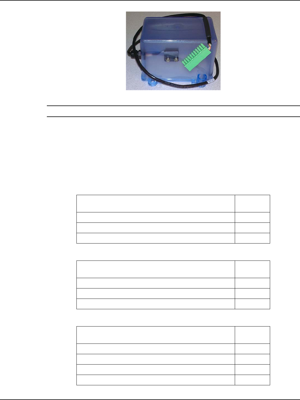
Figure 1 - 2. Mini Switch Kit for Plastic Index
NOTE: GPR switch cable color may vary from that shown in photos.
Table 1-2. American Meter Index Cover Mini Switch Kits
Description Part
Number
Index Cover Assy, Am AL800, 2-Way SSP 40-2474
Index Cover Assy, AL800 100ft, 2-Way SSP 40-2475
Index Cover Assy, Am Res AL425 2-Way SSP 40-2473
Table 1-3. American Large Diaphragm Meter Dial Wheels
Description Part
Number
Dial Wheel, Balanced, C+I, Epoxy 40-1538
Dial Wheel, Index Face Mount, Epoxy 40-1742
0.030” Shim, Dial Wheel, Orange, Polyester 29-1300
Chapter 1 - Pre-Installation Landis+Gyr
12 98-1135 Rev AB Installation Guide
GPR + Brackets Kits
Select one based on GPR location on meter.
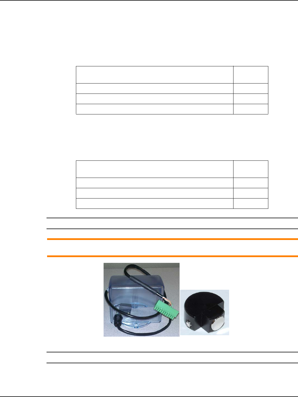
Figure 1 - 3. Mini Switch Kit for Metal Index
As part of the Required Materials, part number 45-1189, 45-1190, or 45-1193, American Large
Diaphragm GPR Kit, includes the following components: 45-1185, GPR Assembly w/ Universal
Bracket; 45-1205 Hardware Kit, American Large Diaphragm.
NOTE: Bracket 28-1440, can be used in either front-left or back-right orientations.
Table 1-4. American GPR + Brackets Kits
Description Part
Number
Kit, GPR Installation, American Large Diaphragm, Alternative Orientation 45-1189
Kit, GPR Installation, American Large Diaphragm, Behind Index 45-1190
Kit, American Large Diaphragm Alternative Orientation GPR 45-1193
Table 1-5. Kit, GPR Installation, American Large Diaphragm, Alternative Orientation #45-1189
Description Part
Number
Bracket, GPR, C&I Gas, American 28-1440
Hardware Kit, American Large Diaphragm, 2-Way 45-1203
GPR Assembly w/ Universal Bracket 45-1185
Table 1-6. Kit, GPR Installation, American Large Diaphragm, Behind Index #45-1190
Description Part
Number
Bracket, GPR, C&I Gas, American, Behind Index 28-1441
Hardware Kit, American Large Diaphragm, 2-Way 45-1203
GPR Assembly w/ Universal Bracket 45-1185

Landis+Gyr Chapter 1 - Pre-Installation
Installation Guide 98-1135 Rev AB 13
NOTE: Bracket, 28-1443, can be used in either front-right or back-left orientations.
NOTE: GPR Cover should not be attached until GPR is fully mounted.
Table 1-7. Kit, American Large Diaphragm Alternative Orientation GPR, #45-1193
Description Part
Number
Bracket, GPR, C & I Gas American, Alternate Orientation 28-1443
GPR Assembly w/ Universal Bracket 45-1185
Hardware Kit, American Large Diaphragm, 2-Way 45-1203
Table 1-8. Hardware Kit, American Large Diaphragm #45-1203
Description Part
Number
Cup, Tamper Seal, C&I, 2-Way Gas 22-1384
Cup, Tamper Seal, C&I Gas 22-0277
Index Screw, Self-threading, 8-18x3/4 inch, Type 25, SS 22-1174
Screw, 12-24x1 inch, Fillister Head, Slotted, SS 22-1383
Tie Wrap, 3.9 inch, UV, Nylon, Black 30-0502
Screw,8-32x5/8 inch, Fillister Head, SS 22-0310
Seal, Residential Gas, Security 29-1557
Seal, Tamper, C&I Gas 22-0278
Table 1-9. GPR Assembly w/ Universal Bracket #45-1185
Description Part
Number
Assy, 2-Way C&I Gas Module 40-1672
GPR, Bracket, Universal, C&I 28-1308
Screw, #6x1/2in, Flat Head, Pin-In-Torx, Self-tap, SS 22-1057
Screw, 10-32x3/8 inch, Pan Head, SS 22-1468
Washer, #10, EXT LK, SS 22-0119
Kit, Hardware, Wall Mount Cover (GPR Cover Mounting Kit) 45-1042
Table 1-10. GPR Cover Mounting Kit #45-1042
Description Part
Number
Seal, Tamper, C&I Gas 22-0278
Screw, #6x1in, Button Head, Pin-In-Torx, T-10, Self-tapping, SS 22-1057
Chapter 1 - Pre-Installation Landis+Gyr
14 98-1135 Rev AB Installation Guide
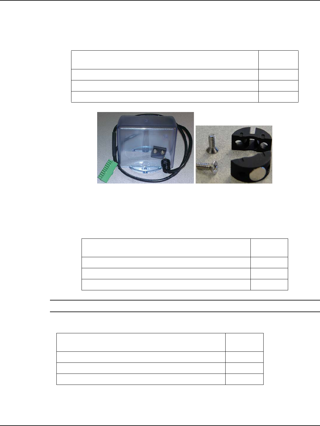
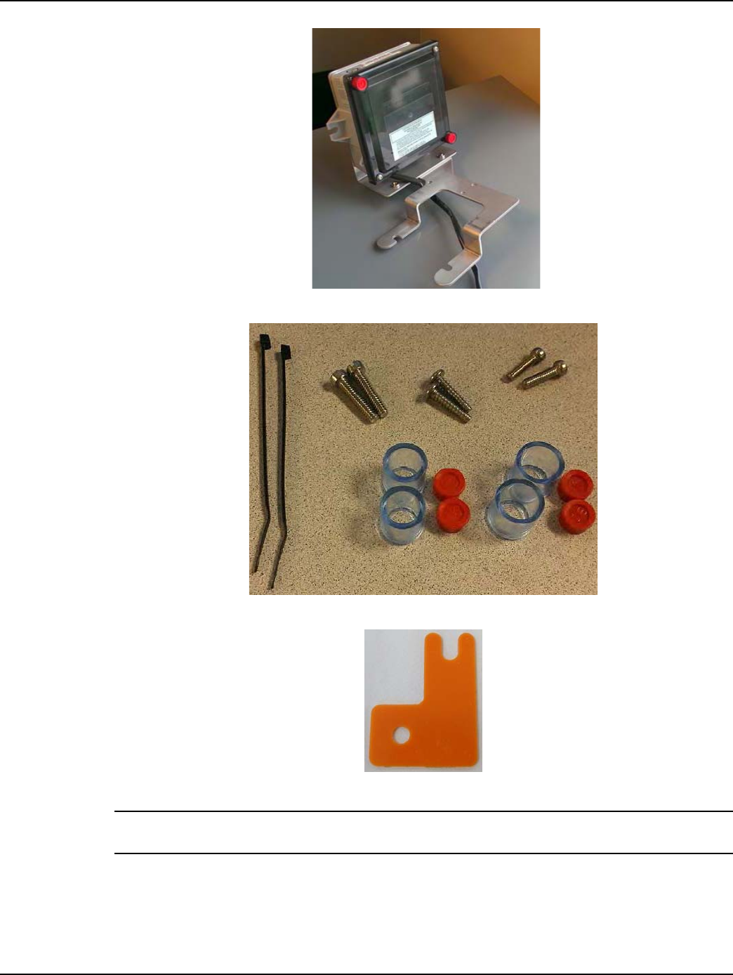
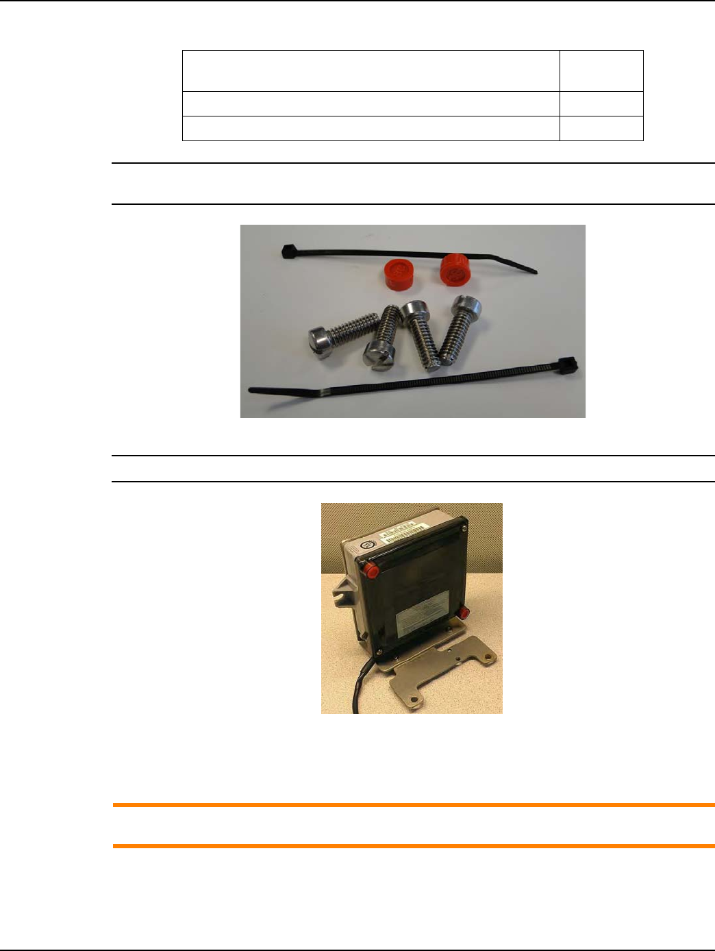
Figure 1 - 4. GPR with American Large Diaphragm brackets and hardware
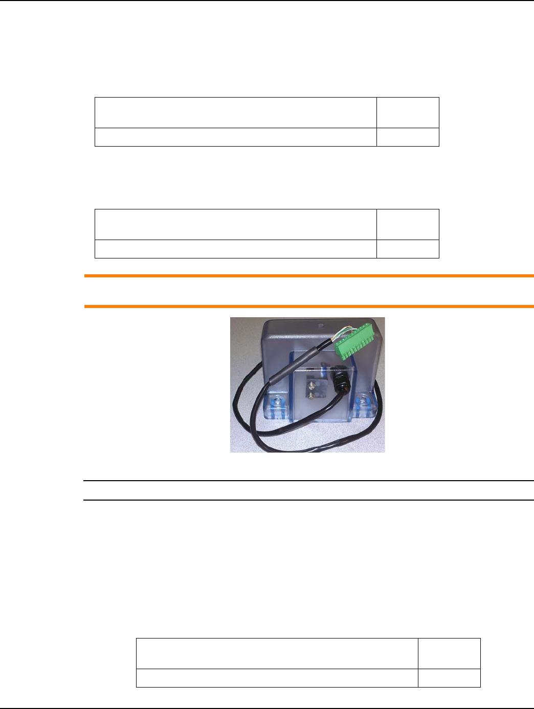
Figure 1 - 5. Hardware Kit #45-1203 for Index Cover and Bracket
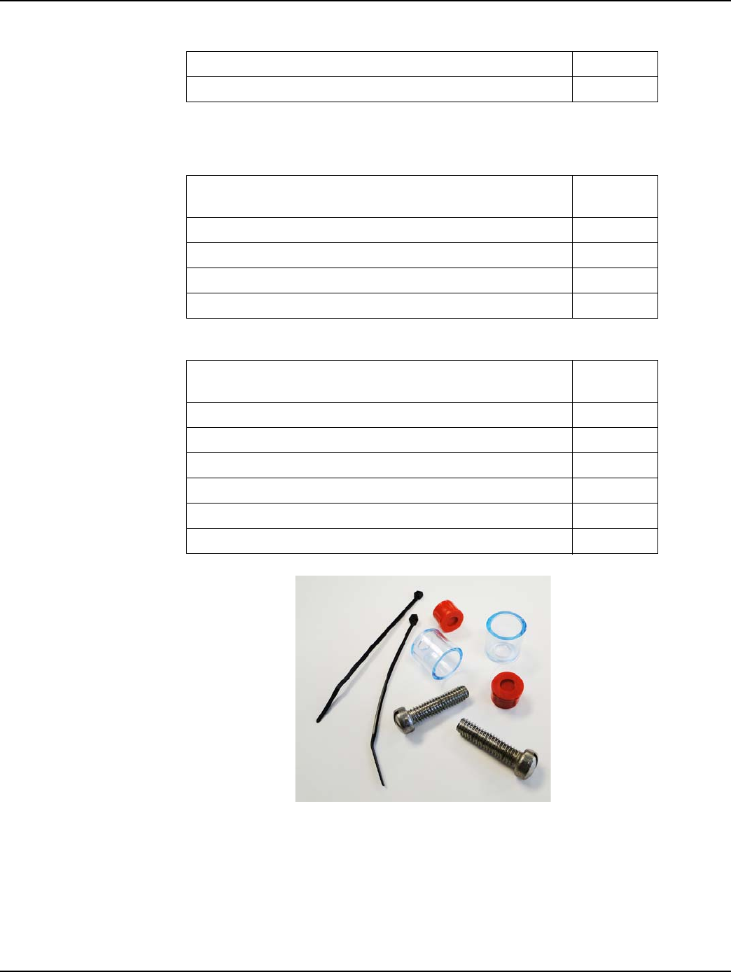
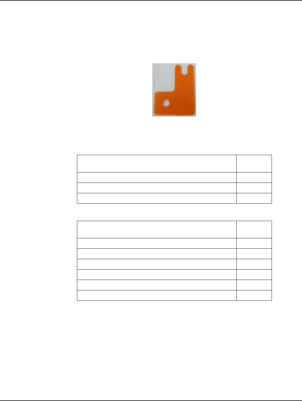
Figure 1 - 6. Part No. 29-1300 0.030” thick Shim for front or back mount Dial Wheel Installation
NOTE: Individual components and kits may be ordered for installing the GPR with American large
diaphragm meters.
Landis+Gyr Chapter 1 - Pre-Installation
Installation Guide 98-1135 Rev AB 15
Rockwell Meters Required Materials
Index Cover Kit
Dial Wheel
ACAUTION: Part numbers are subject to change. Contact the Landis+Gyr Supply Chain for the
latest part numbers.
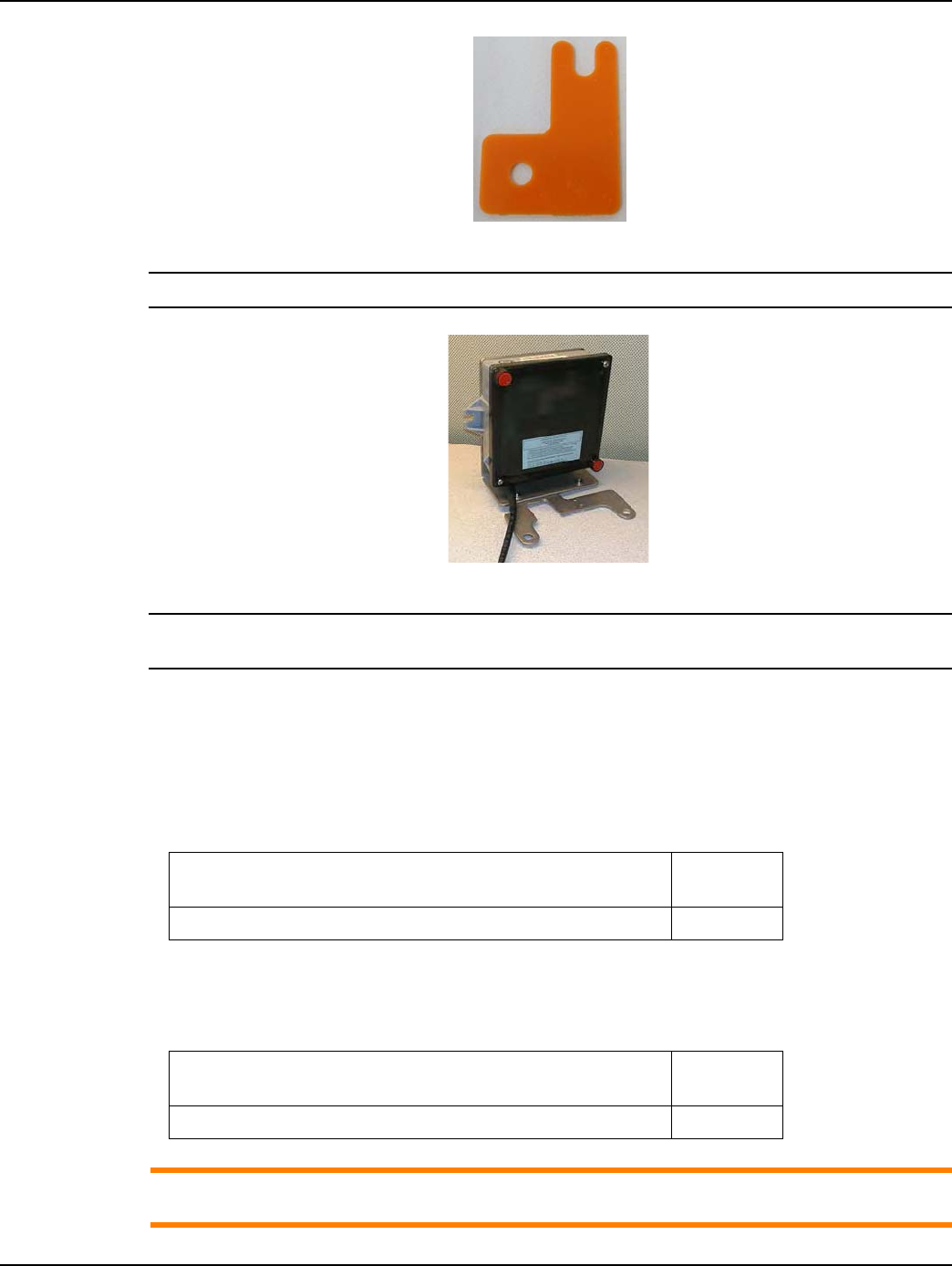
Figure 1 - 7. Rockwell GPR Index Cover and Magnet Wheel
NOTE: GPR switch cable color may vary from that shown in photos.
GPR + Brackets Kit
As part of the Required Materials, part number 45-1186, Kit, Rockwell Large Diaphragm, GPR,
includes the following components:
•45-1185, GPR Assembly w/ Universal Bracket
•45-1169, Rockwell Large Diaphragm Index Cover Hardware Kit
Table 1-11. Rockwell Large Diaphragm Meter GPR Index Cover Kit
Description Part
Number
Index Cover Assy, Rock R750, 2-Way SSP 40-2470
Table 1-12. Rockwell Large Diaphragm Meter GPR Dial Wheel
Description Part
Number
Dial Wheel, Index Back Mount, Epoxy 40-1743
Table 1-13. GPR Installation Kit for Rockwell 750 Large Diaphragm Meter #45-1186
Description Part
Number
Bracket, MM MTG, C&I Gas, Rockwell 28-1161
Chapter 1 - Pre-Installation Landis+Gyr
16 98-1135 Rev AB Installation Guide
Figure 1 - 8. Rockwell Large Diaphragm Hardware Kit # 45-1169
Kit, Rockwell Large Diaphragm Index Cover Hardware 45-1169
GPR Assembly w/ Universal Bracket 45-1185
Table 1-14. Kit, Rockwell Large Diaphragm Index Cover Hardware #45-1169
Description Part
Number
Cup, Security, Wedge LOC 22-0281
Screw, 5/16 - 18x1.25 LG, SS, FH 22-1358
Seal, Tamper, MM, RKWL, Cover 22-0275
Tie Wrap, 3.9 inch, UV, Nylon, Black 30-0502
Table 1-15. GPR Assembly w/ Universal Bracket #45-1185
Description Part
Number
Assy, 2-Way C&I Gas Module 40-1672
GPR, Bracket, Universal, C&I 28-1308
Screw, #6x1/2in, Flat Head, Pin-In-Torx, Self-tap, SS 22-1057
Screw, 10-32x3/8 inch, Pan Head, SS 22-1468
Washer, #10, EXT LK, SS 22-0119
Kit, Hardware, Wall Mount Cover (GPR Cover Mounting Kit) 45-1042
Table 1-13. GPR Installation Kit for Rockwell 750 Large Diaphragm Meter #45-1186
Landis+Gyr Chapter 1 - Pre-Installation
Installation Guide 98-1135 Rev AB 17
Figure 1 - 9. Part No. 29-1300 0.030” thick Shim for front or back mount Dial Wheel Installation
NOTE: GPR Cover should not be attached until GPR is fully mounted.
Figure 1 - 10. GPR with Rockwell Large Diaphragm Universal Hardware
NOTE: Individual components and kits may be ordered for installing the GPR with Rockwell large
diaphragm meters.
Schlumberger Meters Required Materials
Index Cover Kit
Dial Wheel
ACAUTION: Part Numbers Are Subject to Change. Contact the Landis+Gyr Supply Chain for
the Latest Part Numbers.
Table 1-16. Schlumberger Large Diaphragm Meter GPR Index Cover Kit
Description Part
Number
Index Cover Assy, Schl 675, 2-Way SSP 40-2471
Table 1-17. Schlumberger Large Diaphragm Meter GPR Back Mount Wheel
Description Part
Number
Dial Wheel, Index Back Mount, Epoxy 40-1743
Chapter 1 - Pre-Installation Landis+Gyr
18 98-1135 Rev AB Installation Guide
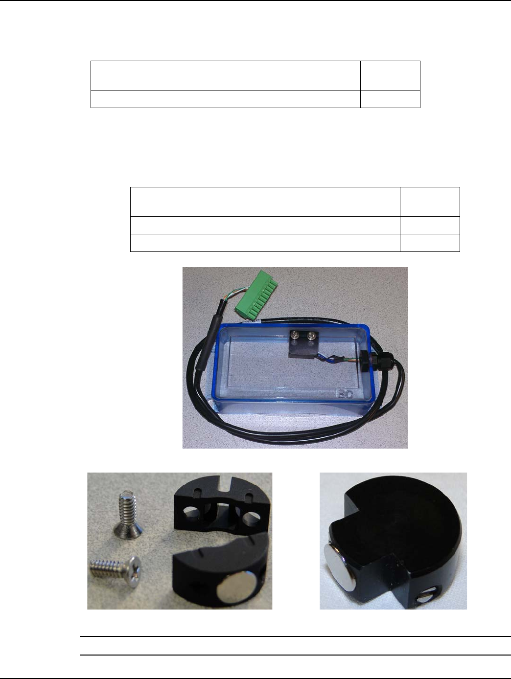
Figure 1 - 11. Schlumberger GPR Index Cover
NOTE: GPR switch cable color may vary from that shown in photos.
GPR + Brackets Kit
As part of the Required Materials, part number 45-1187, the Schlumberger Large Diaphragm GPR
Kit, includes the following components:
•45-1185, GPR Assembly w/ Universal Bracket
•45-1171 Schlumberger Large Diaphragm Index Cover Hardware Kit.
Table 1-18. Schlumberger Large Diaphragm GPR Kit #45-1187
Description Part
Number
Bracket, MM MTG, C&I Gas, Schlumberger 28-1162
GPR Assembly w/ Universal Bracket 45-1185
Kit, Schlumberger Large Diaphragm Index Cover Hardware 45-1171
Table 1-19. Kit, Schlumberger Large Diaphragm Index Cover Hardware # 45-1171
Description Part
Number
SEAL,TAMPER,C&I GAS 22-1289
SCREW,1/4x20x5/8-inch, FILH, SS 22-0312
TIE WRAP, 3.9inch, UV, NYLON, BLACK 30-0502
Table 1-20. GPR Assembly w/ Universal Bracket #45-1185
Description Part
Number
Assy, 2-Way C&I Gas Module 40-1672
GPR, Bracket, Universal, C&I 28-1308
Screw, #6x1/2in, Flat Head, Pin-In-Torx, Self-tap, SS 22-1057
Screw, 10-32x3/8 inch, Pan Head, SS 22-1468
Landis+Gyr Chapter 1 - Pre-Installation
Installation Guide 98-1135 Rev AB 19
NOTE: Individual components and kits may be ordered for installing the GPR with Schlumberger
large diaphragm meters.
Figure 1 - 12. Schlumberger Large Diaphragm Index Cover Hardware (Part# 45-1171)
NOTE: GPR Cover should not be attached until GPR is fully mounted.
Figure 1 - 13. GPR with Brackets and Hardware.
Sprague Meters Required Materials
ACAUTION: Part numbers are subject to change. Contact the Landis+Gyr Supply Chain for the
latest part numbers.
Washer, #10, EXT LK, SS 22-0119
Kit, Hardware, Wall Mount Cover (GPR Cover Mounting Kit) 45-1042
Table 1-20. GPR Assembly w/ Universal Bracket #45-1185
Description Part
Number
Chapter 1 - Pre-Installation Landis+Gyr
20 98-1135 Rev AB Installation Guide
Index Cover Kit
Dial Wheel
Select one based on index type.
Figure 1 - 14. Sprague 1000 GPR Index Cover Assembly
Figure 1 - 15. Front or Back Mount and Balanced Dial Wheels
NOTE: GPR switch cable color may vary from that shown in photos.
Table 1-21. Sprague Large Diaphragm Meter GPR Kit
Description Part
Number
Index Cover Assy, Sp 1000, 2-Way SSP 40-2472
Table 1-22. GPR Dial Wheels
Description Part
Number
Dial Wheel, Balanced, C+I, Epoxy 40-1538
Dial Wheel, Index Face Mount, Epoxy 40-1742
Landis+Gyr Chapter 1 - Pre-Installation
Installation Guide 98-1135 Rev AB 21
GPR + Brackets Kit
As part of the Required Materials, part number 45-1188, Sprague Large Diaphragm GPR Kit,
includes the following components:
•45-1185, GPR Assembly w/ Universal Bracket
•45-1114, Sprague Large Diaphragm Index Cover Hardware Kit
Figure 1 - 16. 0.030 Shim for Magnetic Dial Wheel Installation, Part # 29-1300
Table 1-23. GPR Installation Kit for Sprague Large Diaphragm Meters #45-1188
Description Part
Number
Sprague Large Diaphragm Index Cover Hardware Kit 45-1114
GPR Assembly w/ Universal Bracket 45-1185
Bracket, MM MTG, C&I Gas, Sprague 28-1163
Table 1-24. Sprague Large Diaphragm Index Cover Hardware Kit #45-1114
Description Part
Number
Washer, Flat, M5, SS 22-0178
Cup, Tamper Seal, C&I Gas, Sprague 22-0277
Seal, Tamper C&I Gas, Sprague 22-0278
Screw, 10-24 x 3/4 inch, FILH, SS 22-1376
Screw, 10-24 x 7/8 inch, FILH, Slotted, SS 22-1355
Tie Wrap, 3.9 inch, UV, Nylon, Black 30-0502
Chapter 1 - Pre-Installation Landis+Gyr
22 98-1135 Rev AB Installation Guide
Figure 1 - 17. Sprague Large Diaphragm Hardware Kit #45-1114 for Index Cover
NOTE: GPR Cover should not be attached until GPR is fully mounted.
Figure 1 - 18. GPR with Sprague Large Diaphragm Brackets and Hardware
NOTE: Individual components and kits may be ordered for installing the GPR with Sprague large
diaphragm meters.
Table 1-25. GPR Assembly w/ Universal Bracket #45-1185
Description Part
Number
Assy, 2-Way C&I Gas Module 40-1672
GPR, Bracket, Universal, C&I 28-1308
Screw, #6x1/2in, Flat Head, Pin-In-Torx, Self-tap, SS 22-1057
Screw, 10-32x3/8 inch, Pan Head, SS 22-1468
Washer, #10, EXT LK, SS 22-0119
Kit, Hardware, Wall Mount Cover (GPR Cover Mounting Kit) 45-1042
Landis+Gyr Chapter 1 - Pre-Installation
Installation Guide 98-1135 Rev AB 23
Rotary Required Materials
For rotary meters a cable, GPR, and bracket kit are needed.
Cable
Select one based on meter type and its interface.
GPR+ Brackets Kit
NOTE: Tie wrap 22-1417 is needed to tie the cables and is not included in kit.
Table 1-26. Rotary Gas Meter Module Installation Tool List
Torx Pin Head Driver, T10 Flat-tip Screwdriver, 1/4 inch x 5 inch
Torx Pin Head Driver, T15 Wire Cutter\Stripper for 19-26-AWG solid
conductor wire
Flat-tip Screwdriver, 3/16 inch x 4 inch Badger Field Splice Kit 62084-001
Torque Driver \ Wrench, 0.5 inch-pounds to 20 foot-
pounds 3M Scotchlok E-9Y Crimping Tool or Equivalent
Phillips Screwdriver, #2 3M Scotchlok, Model UY2 or Equivalent
Table 1-27. GPR Rotary Meter Cables
Part # Description
19-2330 Cable Assembly, Flying Leads, Single Output, Gas C&I 2-Way
19-2331 Cable Assy, Rotary, Flying Leads, Double Output, Gas C&I 2-Way
19-2332 Cable Assy, Rotary, Gas C&I 2-Way
Table 1-28. GPR Installation Components for Rotary Gas Meters
Part # Description
40-1672 Assy, 2-Way C&I Gas Module
45-0080 GPR Pipe Mount Kit, 2-3 Inch
22-1417 TIE WRAP, 10 inch, UV, NYLON, BLACK

Chapter 1 - Pre-Installation Landis+Gyr
24 98-1135 Rev AB Installation Guide
Dresser Roots Required Materials
Meter Adapter Kit (Ordered from GE)
Gridstream Module
Index
Table 1-29. GE AMR Adapter Kit
Part Number
(GE) Description
45-2476 Adapter Kit, Dresser Roots, GE AMR
Table 1-30. Gridstream American Residential Module
Part
Number Description
26-1307 ResGas, Endpoint, American Long Pin
Table 1-31. Index with Consumption Pointers Removed
Part
Number Description
45-2400 American Index, Pointers Removed, GE AMR
2
Installation Guide 98-1135 Rev AB 25
Index Cover Pulser Install
and Operation Start Up
Introduction
The index cover pulser has a single channel. The channel is for measuring gas volume pulses. The
pulser is type Form-C. Before starting a module in for the first time, double check the following:
•The index cover is properly installed to the meter index.
•The GPR module is properly mounted to the meter.
NOTE: The output of the pulser is to be connected to Channel B on the GPR.
NOTE: It is the responsibility of the user to make sure the output pulse meets the minimum pulse
ON/OFF time of 50ms/50ms.
NOTE: If the battery is unplugged, do not connect the battery until the module is ready for operation
to start.
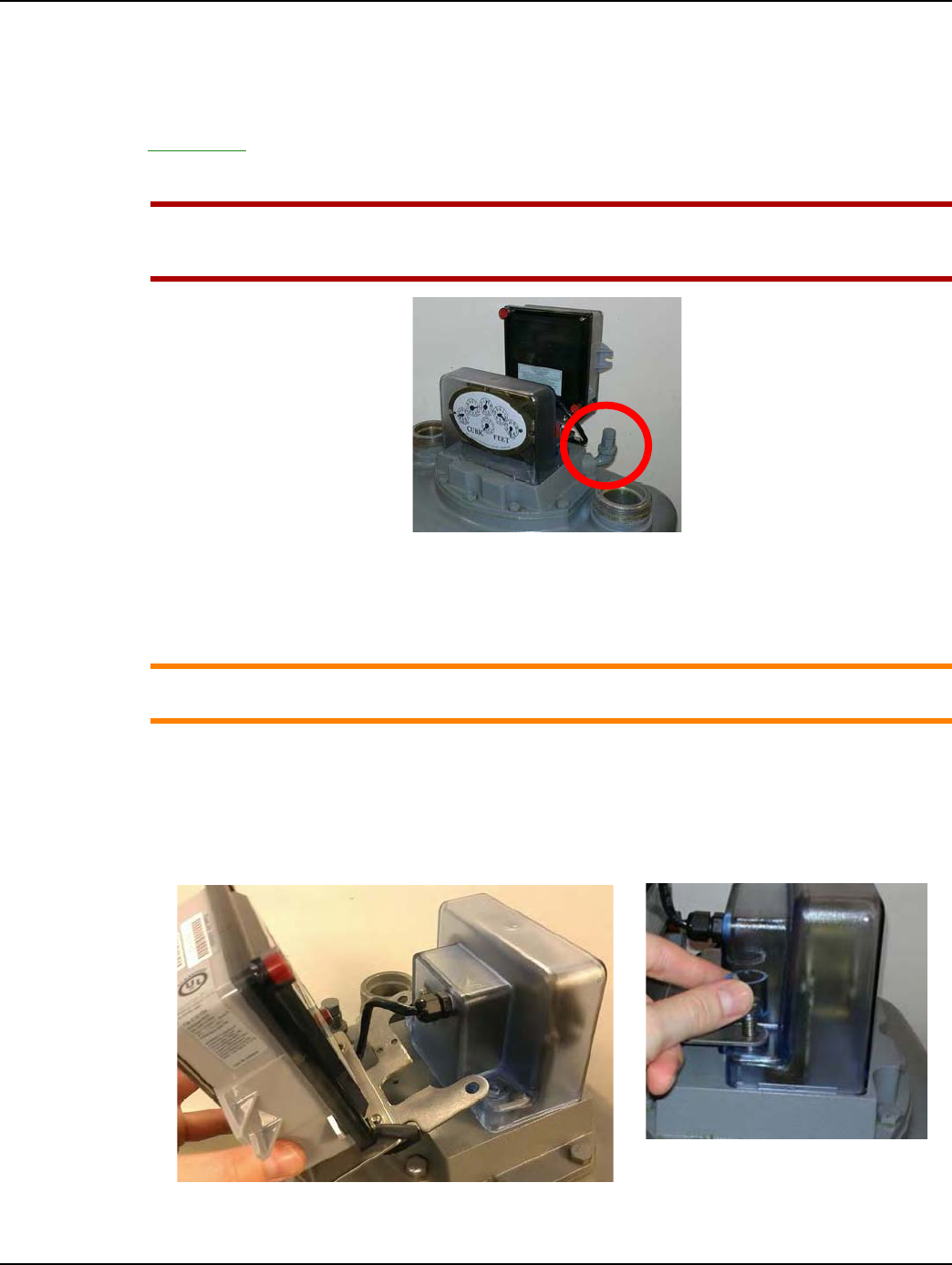
Figure 2 - 1. Sensor Channels
Chapter 2 - Index Cover Pulser Install and Operation Start Up Landis+Gyr
26 98-1135 Rev AB Installation Guide
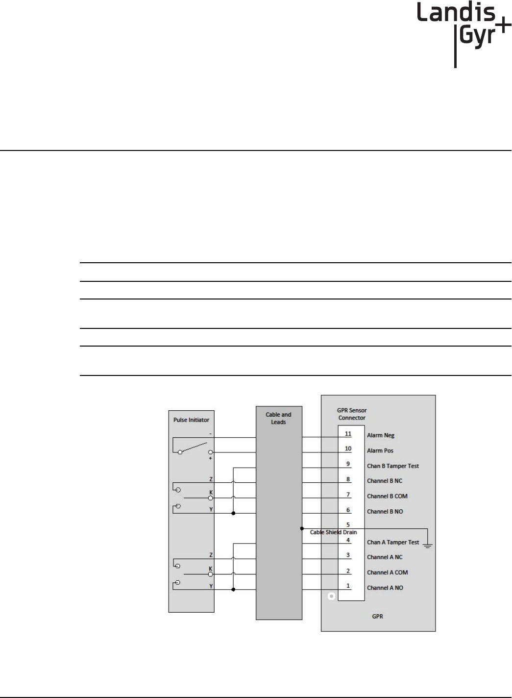
Interface to a Single Form-C Volume Output
The interface to a single Form-C volume pulse output from the index cover is shown in the figure
and table below.
Figure 2 - 2. Wiring for a Single Form-C Volume Input
Landis+Gyr Chapter 2 - Index Cover Pulser Install and Operation Start Up
Installation Guide 98-1135 Rev AB 27
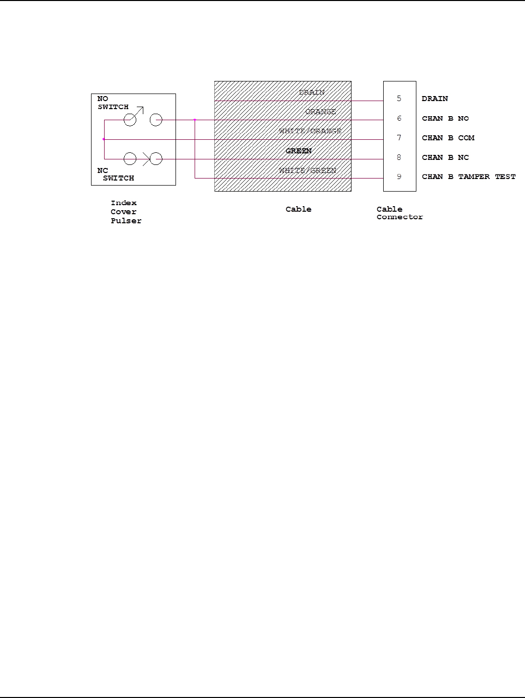
NOTE: The cable connector is shown downside up.
Figure 2 - 3. Cable to GPR Connection for a Single Form-C Volume Input
The connector on the cable is mated to the channel B on the GPR Sensor Connector as shown in the
figure below.
NOTE: Battery should not be connected until GPR is fully mounted.
Table 2 - 1. Single Form-C Volume Wiring Definitions
GPR Sensor Index Cover
GPR Sensor
Connector Pin # Signal and Description Lead Color Terminal Description
and notes
1 N/C N/A N/A Not Applicable
2 N/C N/A N/A Not Applicable
3 N/C N/A N/A Not Applicable
4 N/C N/A N/A Not Applicable
5 Ground Drain N/A Not Applicable
6CHAN B NO, Channel B
normally open Orange NO Normally Open
7CHAN B COM, Channel
B common WHITE/ORANGE COM Common
8 CHAN B NC Green NC Normally Closed
9CHAN B TAMPER TEST,
channel B tamper test WHITE/GREEN NO Tamper Test
10 N/C N/A N/A Not Applicable
11 N/C N/A N/A Not Applicable
Chapter 2 - Index Cover Pulser Install and Operation Start Up Landis+Gyr
28 98-1135 Rev AB Installation Guide
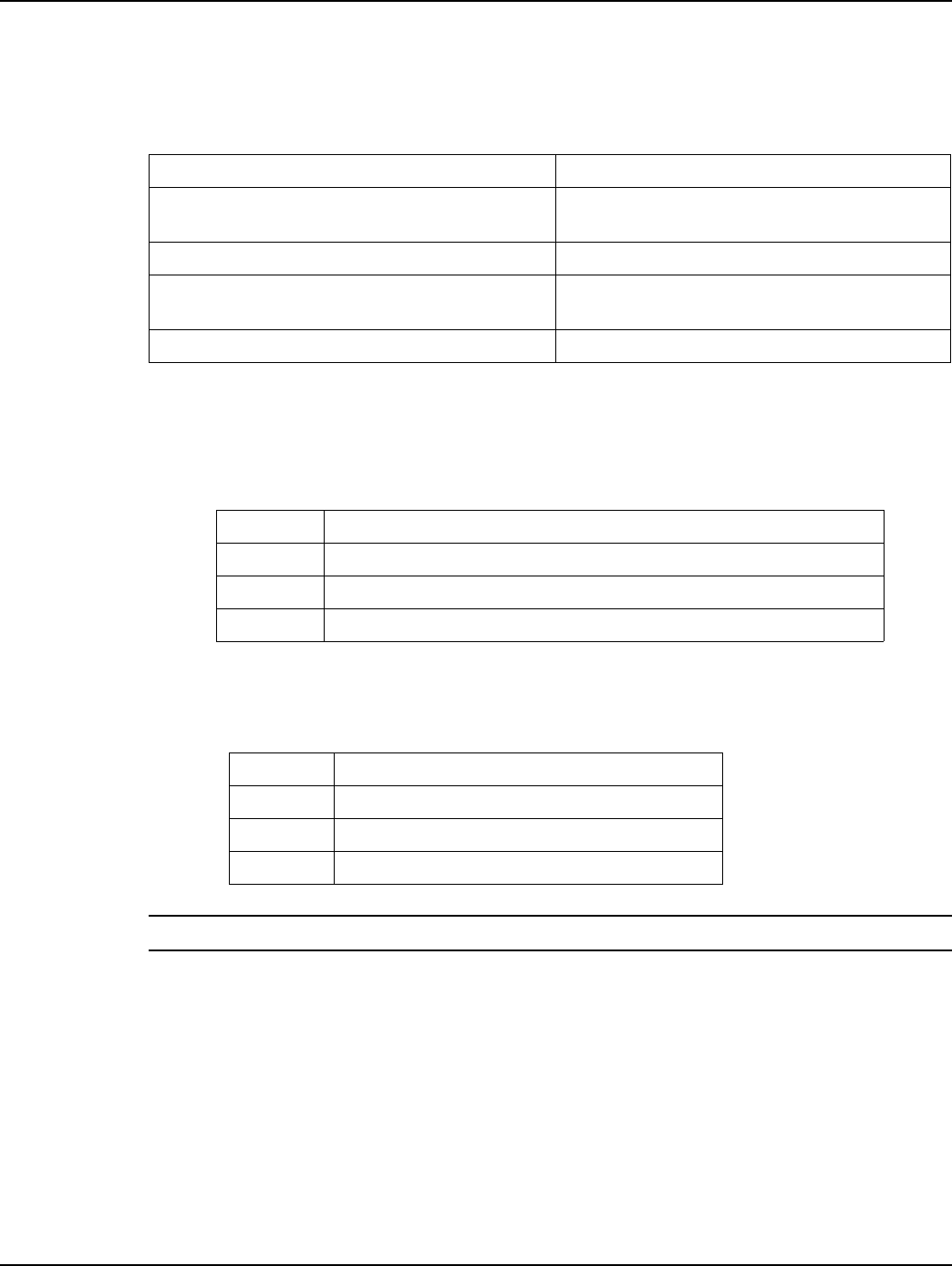
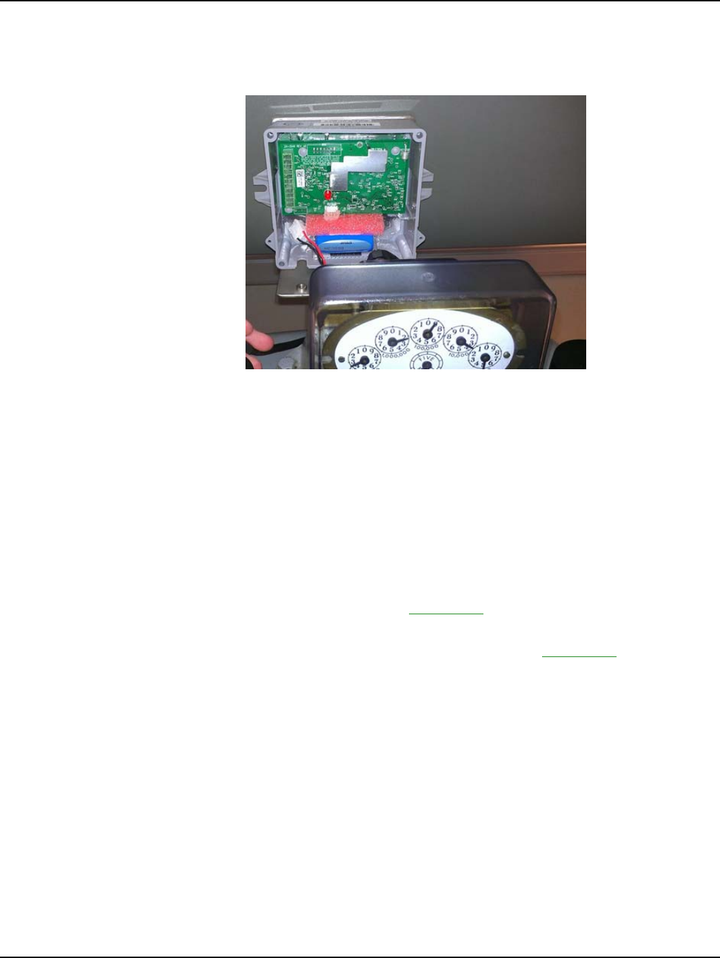
Start the GPR Operation In Install Mode
By now, the GPR should be fully mounted without it's cover (Rockwell meter shown for reference):
Figure 2 - 4. Mounted GPR
The GPR module, as received from the contract manufacturer, should have the correct Network
LAN ID and CRC numbers already configured. The GPR, when installed for the first time, will start
operation in Install Mode. Install Mode is a temporary operation mode during which the GPR
initiates the first network synchronization, and performs auto-registration to Command Center. To be
able to sync to a network the GPR must have the same CRC number as that of the Network. During
auto-registration the GPR requests for operation and meter specific configurations from Command
Center. When the new configuration data is obtained, the GPR reconfigures itself, reboots, and then
changes operation to Normal Mode.
To start the GPR in Install Mode follow the procedure below.
1. Apply dielectric Grease Compound to the sensor cable connector and make the connection as
described in the interface section above. See Appendix A, GPR Waterproofing for more
information.
2. Apply Di-Electric Grease Compound to the battery connector. See Appendix A, GPR
Waterproofing for more information.
3. Install the sensor cable connector before the battery connector to avoid creating false counts.
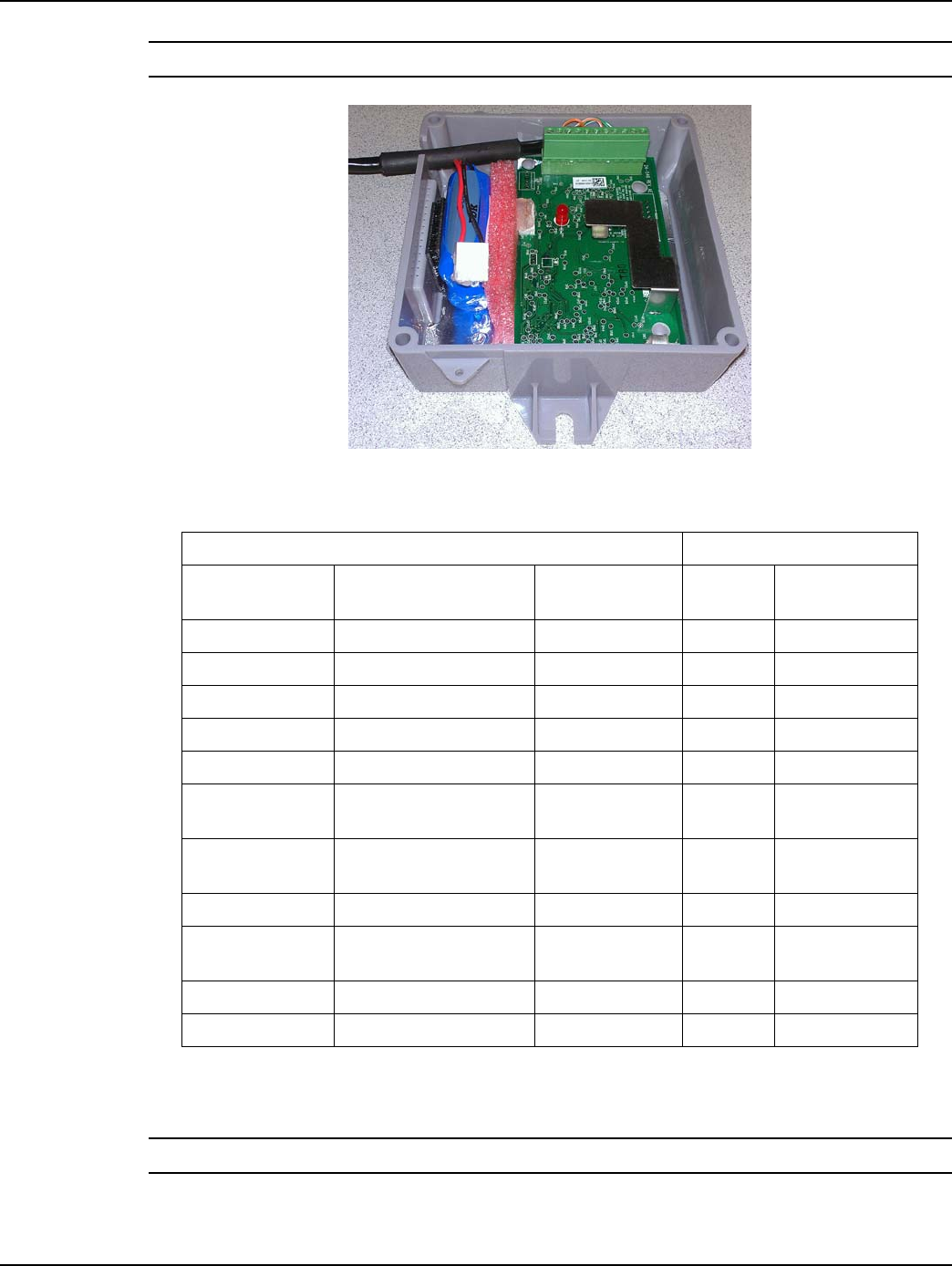
4. Apply power to the module by making the battery connection.
5. Remove and discard the foam between battery and PCBA.
6. Observe the LED on the module for proper start up. Shortly after power is applied, the LED will
flash once every 5 seconds for 60 seconds to indicate to the installer that the module is in
Installation Mode and is operating normally. If an error is encountered, the LED will flash twice
per second to indicate there is error and continue flashing until power is disconnected.
7. If the module started operation correctly, mount the cover using the next 3 steps.
8. Arrange the GPR Pulse Input and Battery Interface cables as shown in Figure 2 - 5. The cables
must not interfere with or block the GPR antenna.
Landis+Gyr Chapter 2 - Index Cover Pulser Install and Operation Start Up
Installation Guide 98-1135 Rev AB 29
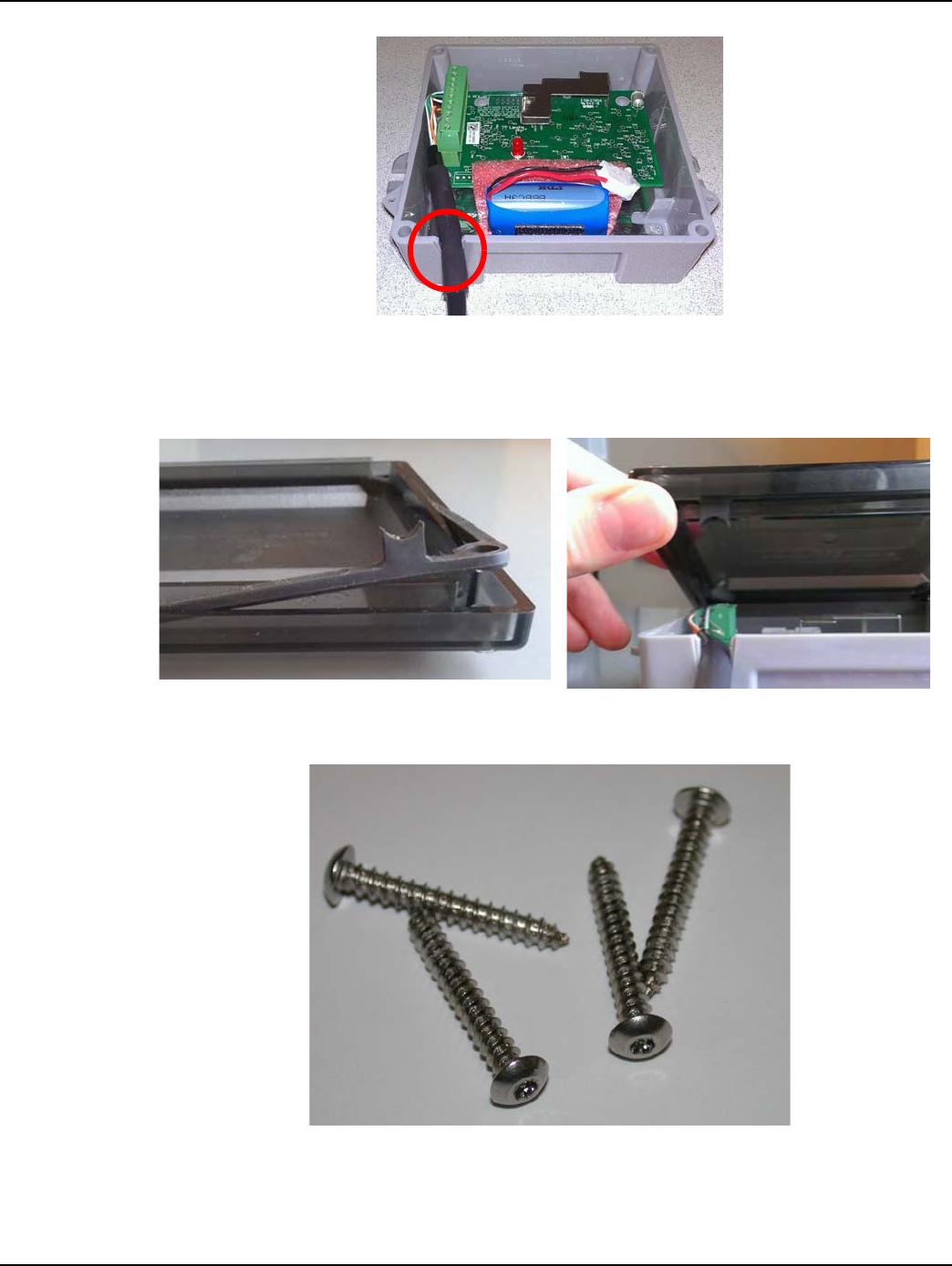
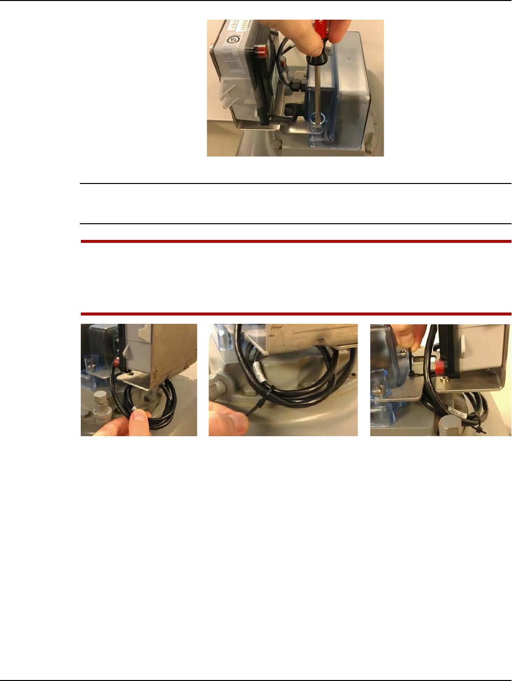
Figure 2 - 5. Pulse Interface Cable's Shrink Tubing Must Route Through GPR Strain Relief Slot
9. Install the GPR cover using the four security Torx screws included with the GPR. The cover
must be installed with the gasket tab inserted into the strain relief slot located at the bottom left
corner of the GPR enclosure as shown in the following photos.
Figure 2 - 6. GPR Cover Gasket Tab and Cover Strain Relief Slot
10. Tighten the screws to 13 inch-pounds (± 1 inch-pound).
Figure 2 - 7. GPR Cover Screws
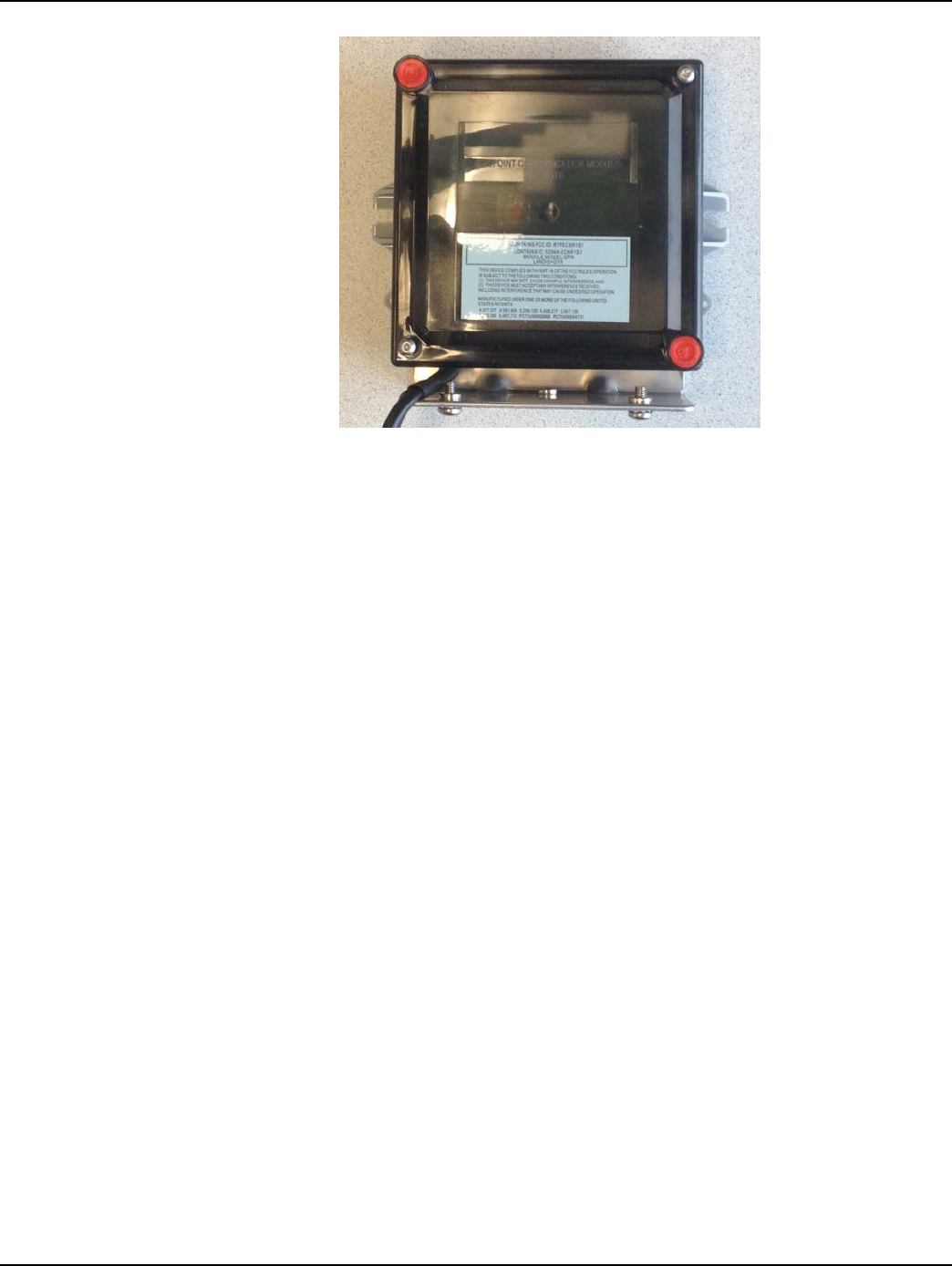
11. Install tamper seals into the tamper cups that are part of the GPR cover.
12. Installation is now complete.
Chapter 2 - Index Cover Pulser Install and Operation Start Up Landis+Gyr
30 98-1135 Rev AB Installation Guide
Figure 2 - 8. GPR Installation Complete
3
Installation Guide 98-1135 Rev AB 31
American GPR Index Cover
& GPR Install
American Index Cover & and Gas Module Removal
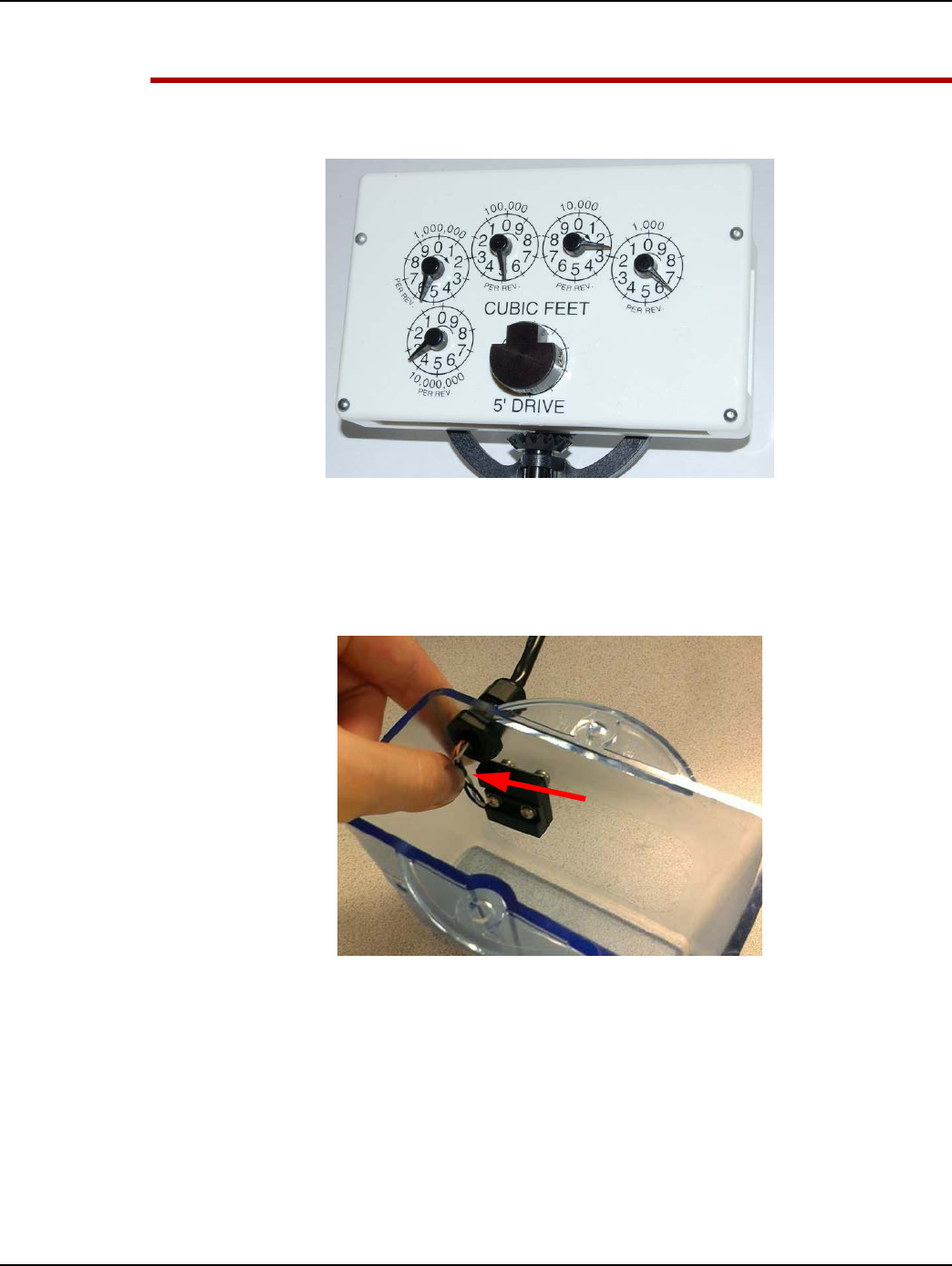
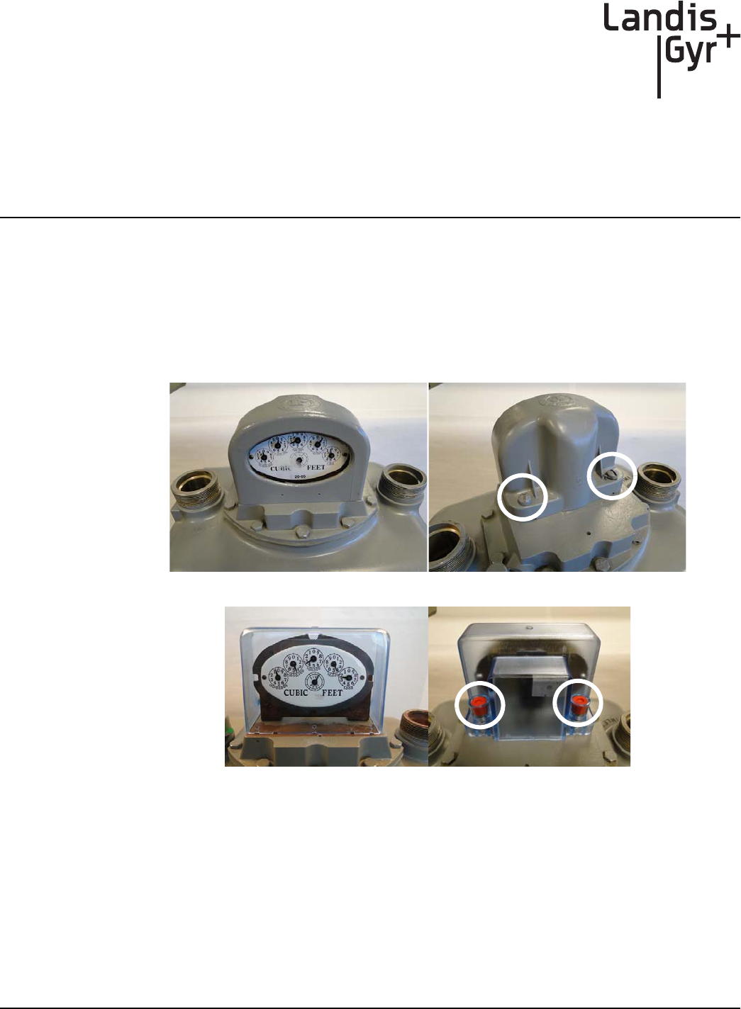
Figure 3 - 1. American Large Diaphragm Meter
Meter Preparation
1. Remove the tamper seals, screws, and index cover assembly from the meter.
2. If the meter has an existing Commercial Gas Module, perform the following steps.
A. Remove the index cover tamper seals.
B. Remove the module bracket tamper seals.
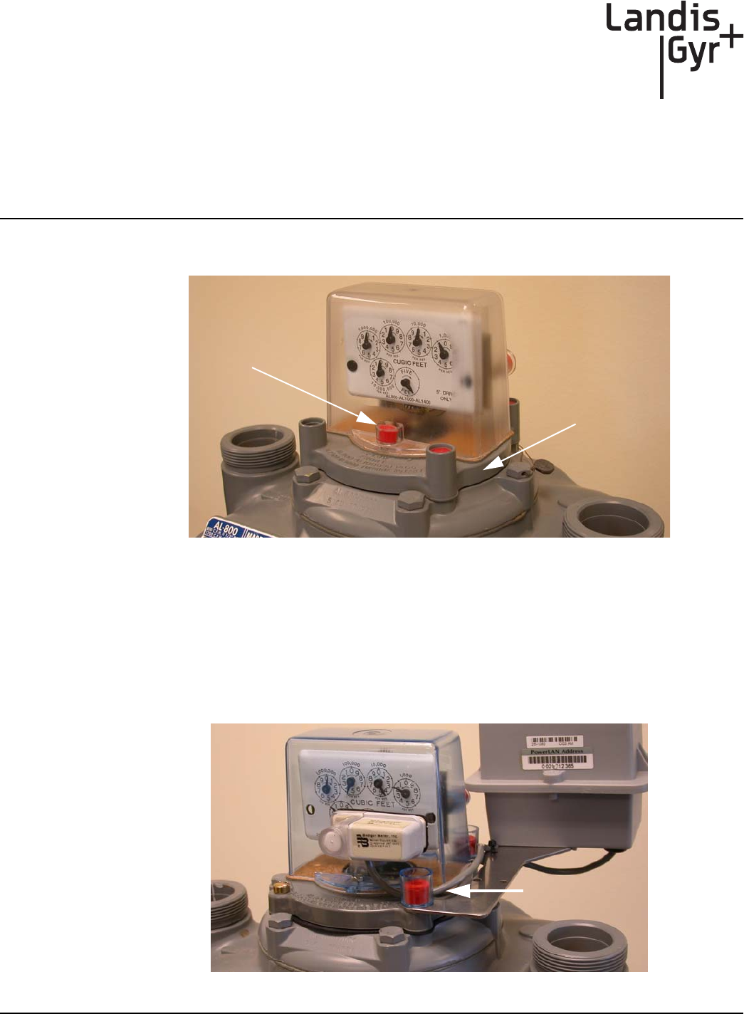
Figure 3 - 2. American Large Diaphragm Meter with Commercial Gas Module
Index Cover
Tamper Seal
Base Plate with
Tamper Seal
Towers
Remove Bracket
Tamper Seals
Chapter 3 - American GPR Index Cover & GPR Install Landis+Gyr
32 98-1135 Rev AB Installation Guide
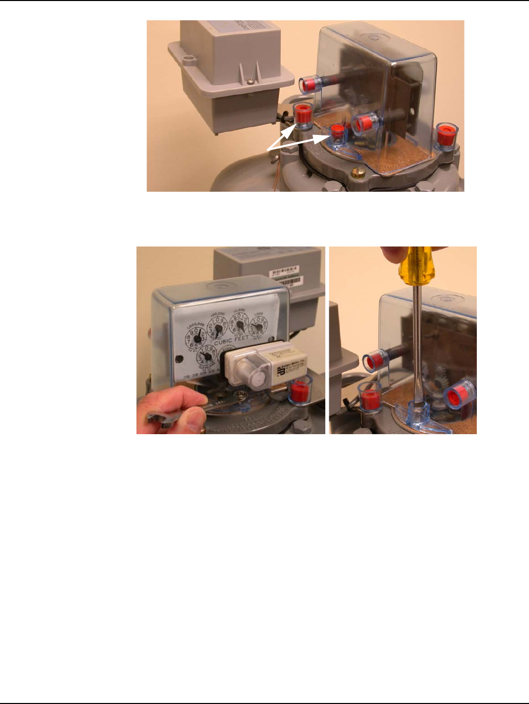
Figure 3 - 3. Remove Index Cover and Module Bracket Tamper Seals
C. Remove the index cover fasteners. If needed, use a 5/16 inch combination wrench to loosen
the index cover front bolt.
Figure 3 - 4. Remove Index Cover Fasteners
D. Remove the module bracket fasteners and carefully disconnect the module and index cover
assembly from the meter.
E. If the original gasket is damaged or cannot be reused, replace the index cover gasket. A
scraper and wire brush may be required to remove leftover gasket material.
3. Meter base plates without built-in tamper seal cups/towers, must use tamper seals and cups as
shown in Figure 3 - 5.
Remove Tamper Seals
Landis+Gyr Chapter 3 - American GPR Index Cover & GPR Install
Installation Guide 98-1135 Rev AB 33
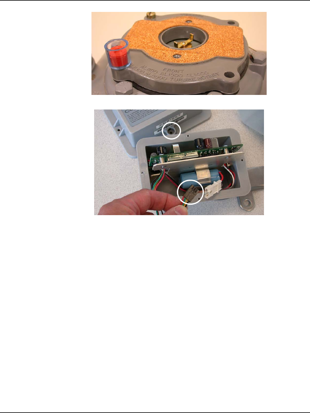
Figure 3 - 5. Cover Gasket and Base Plate with Optional Tamper Cup & Seal
Figure 3 - 6. Commercial Module Cover Removed
4. Swipe each end of the module with an RF Buster or magnet to force the module to save meter
data to non-volatile memory. Remove the Commercial Gas Module tamper seals, screws, and
cover. Disconnect the battery.
5. The Commercial Gas Module must be disassociated from the meter.
6. Disconnect the module from the programming device. Leave the battery disconnected, replace
the module cover, and return the module to the Landis+Gyr cross-dock.
American Mini Switch Kit Installation
Meter Preparation
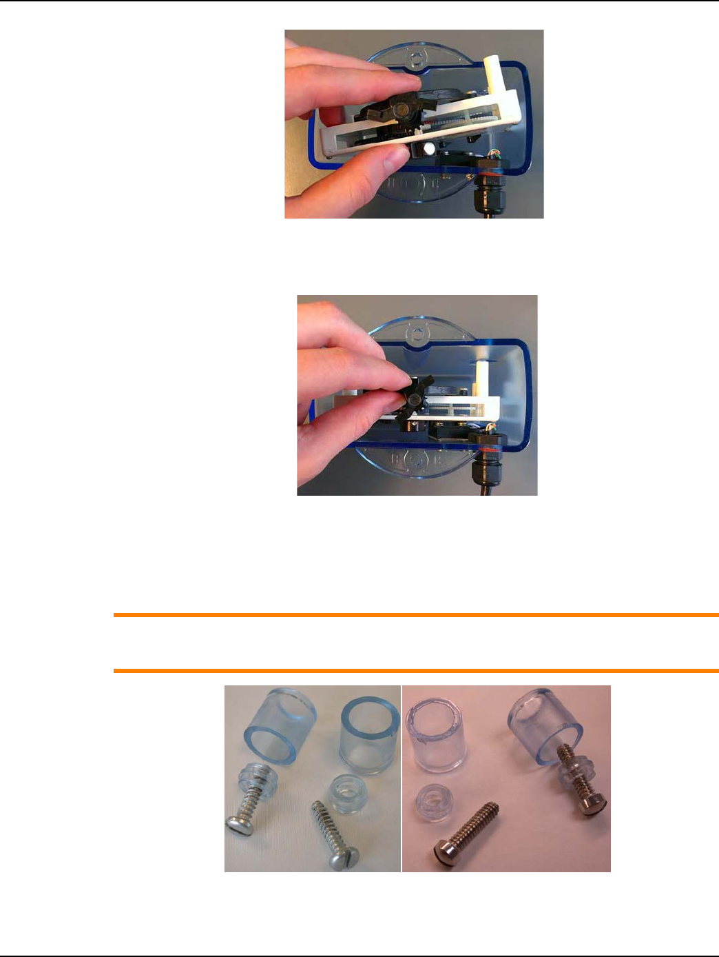
1. Remove the tamper seals and screws from the index cover as shown in the following photos.
Cover Tamper Seal
Location
Serial/Power
Connector
Chapter 3 - American GPR Index Cover & GPR Install Landis+Gyr
34 98-1135 Rev AB Installation Guide
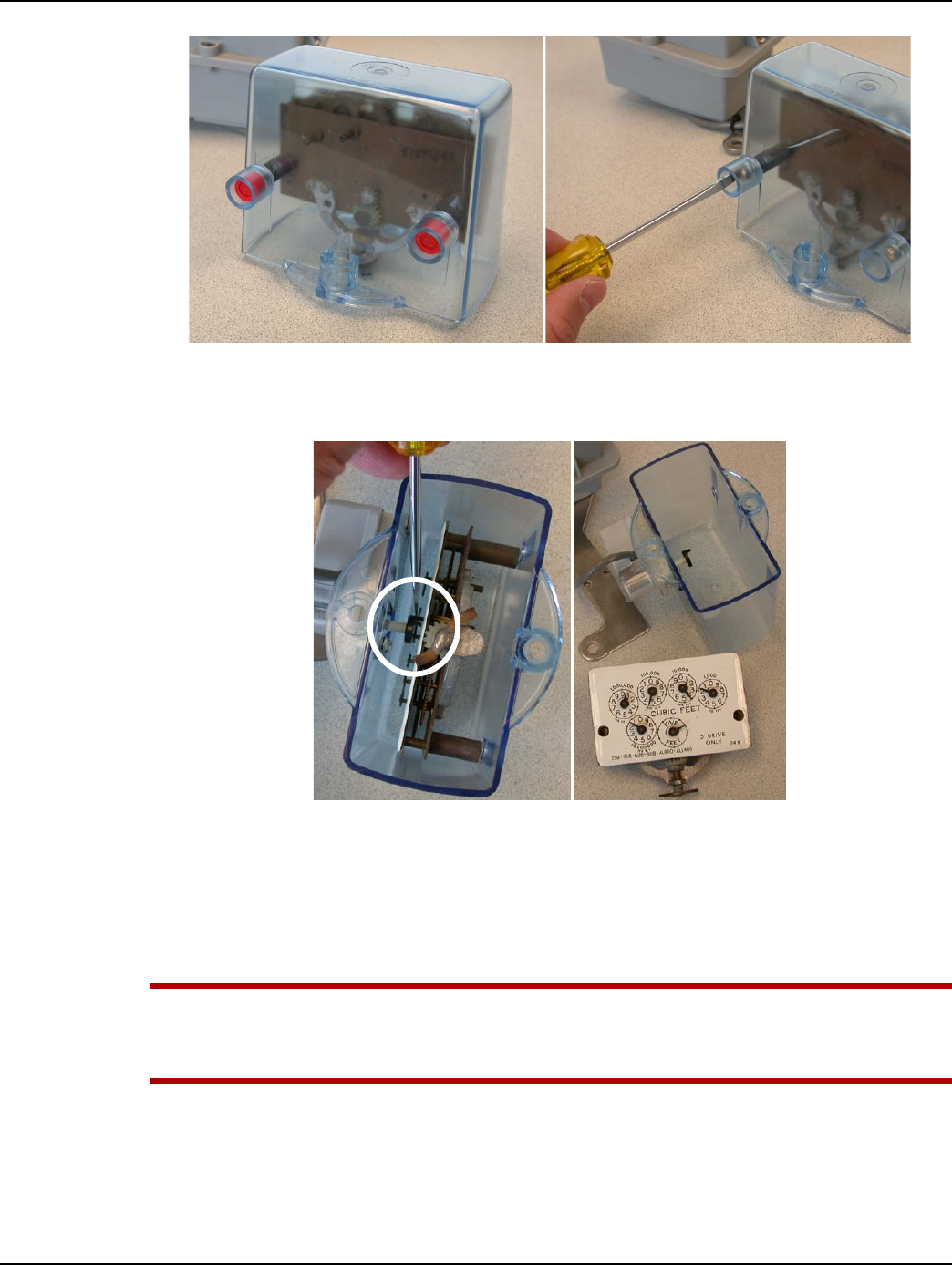
Figure 3 - 7. Remove Index Cover Tamper Seals and Screws
2. Gently push the Badger dial wheel toward the front of the index cover and away from the index
dial pointer. Lift the index out of the cover.
Figure 3 - 8. Disengage Badger Dial Wheel from Index; Remove Index from Cover
3. Inspect the index and replace it if any of the following conditions exists:
•Pointers are loose on their shafts.
•Index face contains cracked or peeling enamel.
•Index drive mechanism does not rotate easily.
UWARNING:
The Index Face Mount Dial Wheel (40-1742) must be used with metal pointer indexes.
The Balanced dial wheel (40-1538) must be used on plastic pointer indexes.
Landis+Gyr Chapter 3 - American GPR Index Cover & GPR Install
Installation Guide 98-1135 Rev AB 35
Installing Index Face Mount Dial Wheels on Metal Pointer Indexes
UWARNING: For Index Face Mount Dial wheels with alignment slots, the wheels must be
installed so that the alignment slots on each wheel half are on top as shown in the next
figure.
Figure 3 - 9. Where Alignment Slots Are Present On Index Face Mount Dial Wheels, The Slots Must
Be Installed On Top
NOTE: For wheels WITHOUT alignment slots, there is no top or bottom, and there is no special
consideration regards dial wheel assembly.
1. Insert screws into the notched dial wheel half.
Figure 3 - 10. Magnetic Dial Wheel Half with Screws Inserted
2. Rotate the index drive mechanism so that the metal proving/test pointer is in an upward
direction.
NOTE: For wheels WITHOUT alignment slots, there is no top or bottom, and there is no special
consideration regards dial wheel assembly.
3. Position the screw-bearing notched wheel half for installation by sliding it downward over the
index proving/test pointer tip as shown in Figure 3 - 11. The two alignment slots and pointer
notch must be visible on top of the wheel half.
Chapter 3 - American GPR Index Cover & GPR Install Landis+Gyr
36 98-1135 Rev AB Installation Guide
Figure 3 - 11. Slide Screw-bearing Wheel Half Over Index Proving/Test Pointer Tip
4. Position the bottom wheel half against the back of the index pointer. Use a small Phillips-type
screwdriver and turn each screw a few turns until they begin to thread into the bottom wheel
half. Do not tighten the screws.
Figure 3 - 12. Thread Screws into Bottom Wheel Half
5. Insert the 0.030 inch thick spacer shim beneath the dial wheel as shown in Figure 3 - 13. Hold
the dial wheel as shown. Tighten each screw a few turns at a time so that the two wheel halves
remain parallel with each other. Tighten the screws to 3.5 inch-pounds (± 0.50 inch-pounds).
Remove the spacer shim.
UWARNING: The main index drive shaft must remain free to rotate while the wheel screws are
tightened to prevent damage to the index pointer and pointer shaft.
Landis+Gyr Chapter 3 - American GPR Index Cover & GPR Install
Installation Guide 98-1135 Rev AB 37
Figure 3 - 13. Insert 0.030 inch thick Shim and alternately tighten the Dial Wheel Screws to 3.5
inch-pounds (± 0.50 inch-pounds).
UWARNING: To avoid damaging the index pointer and dial wheel, take care not to over-tighten
the set screws.
Figure 3 - 14. Index Face Mount Dial Wheel Installed
6. Verify that the dial wheel rotates freely without rubbing the index surface.
ACAUTION: The installed dial wheel shall not move from the installed position, and cannot
physically contact the index face or other pointers on the index. If contact occurs, the index
should be replaced with an approved index. If the replacement index has plastic pointers,
make sure you follow the applicable Dial Wheel installation instructions for plastic pointers
instead (use the Balanced Dial Wheel).
Installing Balanced Dial Wheels on Plastic Pointer Indexes
1. Using a small flat blade screw driver, turn each screw counter-clockwise until the tip of each
screw is flush with the inner surface of the wheel.
Chapter 3 - American GPR Index Cover & GPR Install Landis+Gyr
38 98-1135 Rev AB Installation Guide
Figure 3 - 15. Top View - Balanced Wheel With Screws Backed Out
Figure 3 - 16. Bottom View - Balanced Wheel
2. Position the Balanced dial wheel over the plastic index proving/test pointer as shown in the
following figures. The bottom of the dial wheel is slotted so that it may only be installed with the
slot in the same direction as the index pointer.
3. Insert the 0.030” thick shim beneath the dial wheel. (An orange colored shim is shown for
illustrative purposes to stand out clearly against the index surface)
4. Position the index facing upward on a work surface or in the palm of your hand so that the main
drive shaft points away from contact with all surfaces as shown in the following figures.
5. Gently press the wheel against the shim with your index finger or thumb. The dial wheel must be
level with the surface of the index.
6. Evenly tighten each screw to 1.20 ± 0.10 in-lb.
UWARNING: The main index drive shaft must remain free to rotate as the wheel screws are
tightened to prevent damage to the index pointer and pointer shaft
Figure 3 - 17. Tighten Dial Wheel Screws to 1.20 inch-pounds (± 0.10 inch-pound)
UWARNING: Take care not to over-tighten the set screws to avoid damaging the index pointer
and dial wheel. The installed dial wheel shall not move from the installed position, and cannot
Landis+Gyr Chapter 3 - American GPR Index Cover & GPR Install
Installation Guide 98-1135 Rev AB 39
physically contact the index face or other pointers on the index. If contact occurs, the index
should be replaced with an approved index.
7. Remove the shim and verify that the wheel rotates freely while remaining level with the index
surface.
Figure 3 - 18. Balanced Dial Wheel Installed
Installing Index Into Index Cover
1. Gently press the cable toward the front of the cover to provide clearance for installation of the
index and to prevent stress or damage to the wires.
Figure 3 - 19. Gently Move Cable To Provide Clearance For Index
2. Hold the index at an angle to initially clear the wires and gently slide it into the cover while
holding the wires out of the way as shown.
Chapter 3 - American GPR Index Cover & GPR Install Landis+Gyr
40 98-1135 Rev AB Installation Guide
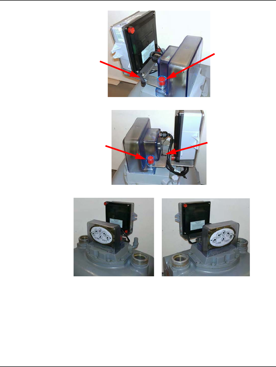
Figure 3 - 20. Insert the Index At an Angle To Clear Wires and Switch During Installation
3. As the index passes by the wires toward the switch, gently rotate the index into its normal
mounting position.
Figure 3 - 21. Position Index In Normal Mounting Location
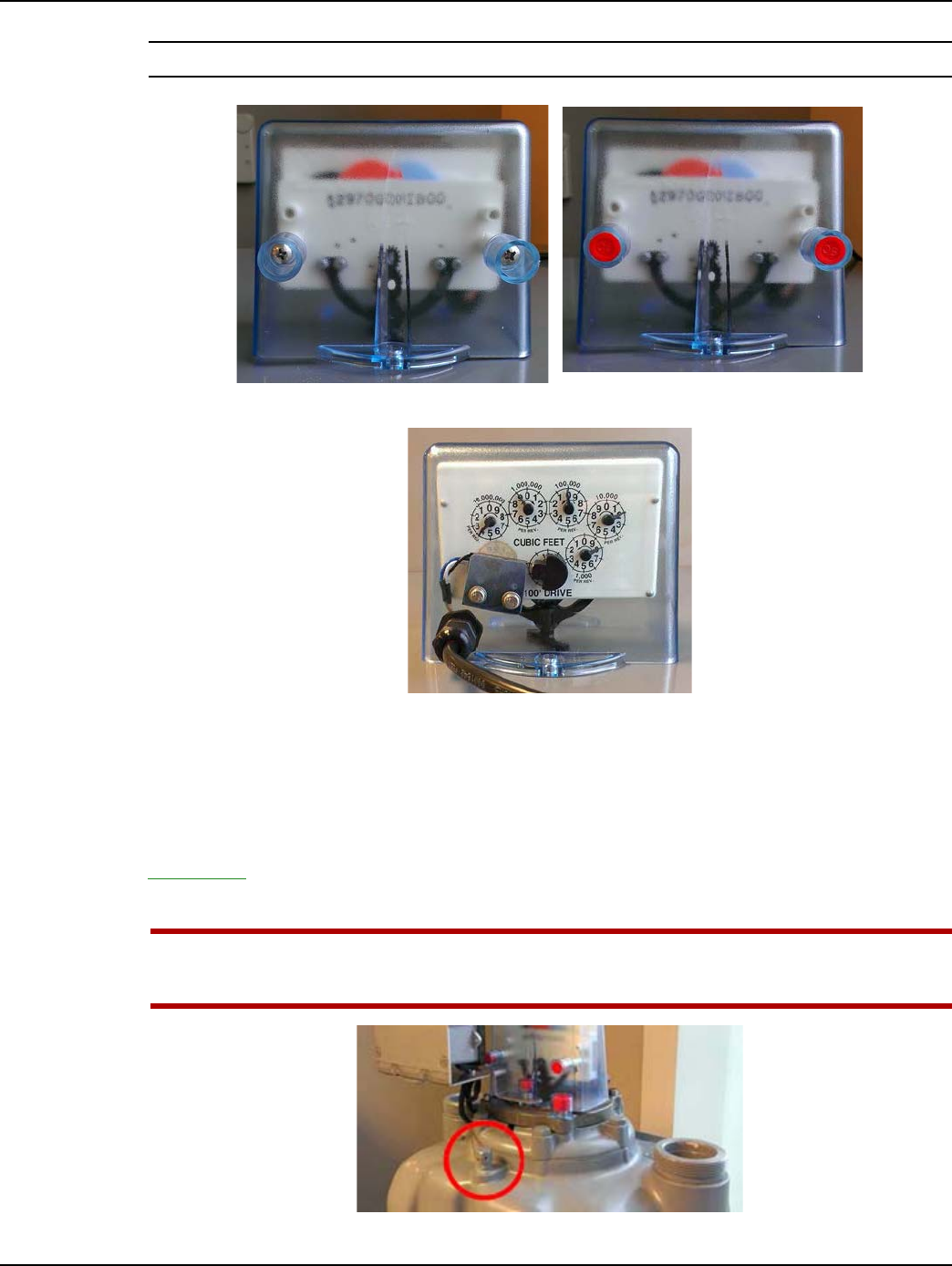
4. From the hardware kit, install the two smaller tamper cups, washers, and screws as shown in the
following photos. Use the Type 25 8-18 x 3/4 inch, self-threading screws (part# 22-1174) with
plastic indexes. Use the 8-32 x 5/8 inch machine screws (part# 22-0310) with metal indexes.
Torque the screws to 9 inch-pounds (+/- one inch-pound).
ACAUTION: New plastic indexes may require the mounting holes to be pre-threaded prior to
installation into the cover. Pre-threading the plastic index’s mounting holes will help prevent
damage to the index during installation.
Figure 3 - 22. Left: Self-Threading Screws / Right: Machine Screws
5. Install the tamper seals.
Landis+Gyr Chapter 3 - American GPR Index Cover & GPR Install
Installation Guide 98-1135 Rev AB 41
NOTE: Cable color may vary from that shown in photos.
Figure 3 - 23. Install Index Screws and Tamper Seals
Figure 3 - 24. Balanced Dial Wheel on Plastic Pointer Index
GPR Direction
The GPR must face away from nearby walls and should be installed in a location unobstructed by
gas pipes. Refer to "American Changing GPR Orientation" on page -43 for instructions. Refer to
Appendix A, GPR Waterproofing for waterproofing guidelines before attaching connectors. Photos
are for reference only: GPR cover and battery should not be connected until Chapter 2.
UWARNING: The GPR and bracket must not interfere with access to the meter pressure tap.
There must be adequate room for connections to the pressure tap (refer to the following
photo).
Figure 3 - 25. Meter Pressure Tap
Chapter 3 - American GPR Index Cover & GPR Install Landis+Gyr
42 98-1135 Rev AB Installation Guide
GPR Mounting
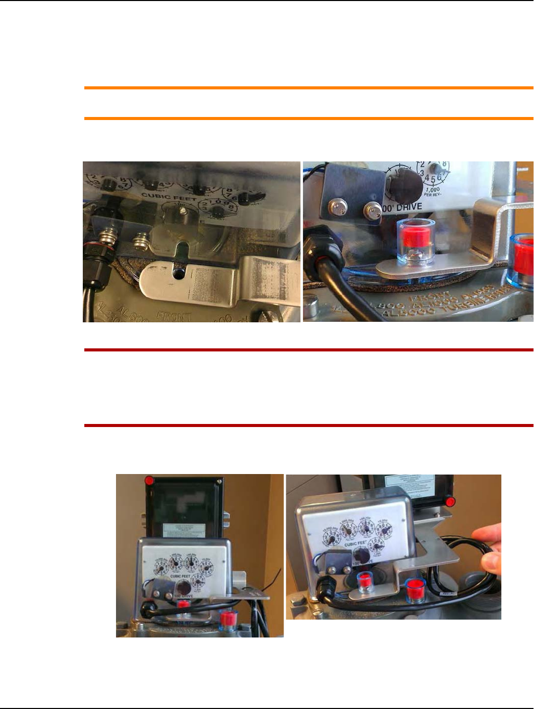
1. Using two #12-24 x 1/2 inch screws (part# 22-0185), install the GPR Mini Switch cover
assembly as shown in the following photographs.
ACAUTION: Check the index cover switch cable assembly for nicks, abrasions, or any damage
prior to installing the assembly onto the meter.
2. Install a new index cover gasket as required. Tighten the screws to 20 inch-pounds (± 5 inch-
pounds.
Figure 3 - 26. Tighten Front and Rear Cover Screws to 20 in-lbs (± 5 in-lbs)
UWARNING: Take care not to pinch the index cover switch cable assembly in any way,
especially during the following installation steps:
During index cover and cable assembly installation onto the meter.
During GPR enclosure cover installation.
Between the GPR and meter brackets and meter.
3. Install front and rear index cover tamper seals.
4. Coil the excess cable. Route it behind the index cover and dress it beneath the GPR bracket.
Figure 3 - 27. GPR at C enter Rear - Using 28-1441Bracket
5. Secure the cable to the bracket immediately below the GPR housing with a black nylon zip tie as
shown in Figure 3 - 28.
Landis+Gyr Chapter 3 - American GPR Index Cover & GPR Install
Installation Guide 98-1135 Rev AB 43
Figure 3 - 28. GPR at C enter Rear - Using 28-1441Bracket
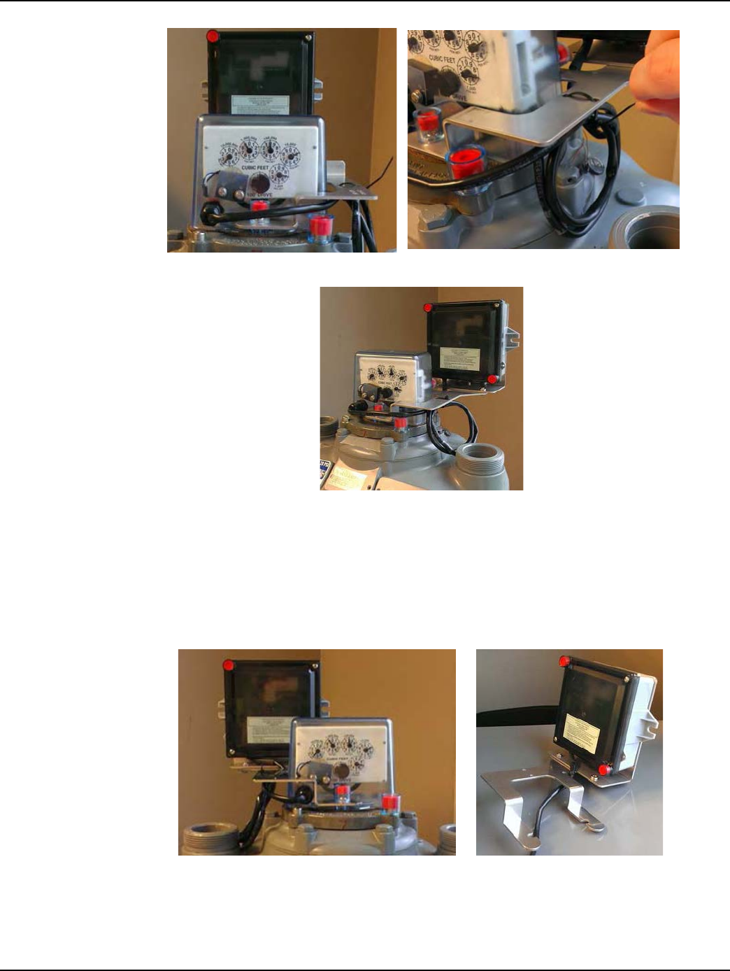
Figure 3 - 29. Final Installation
American Changing GPR Orientation
The GPR must face away from nearby walls. The GPR should be installed in a location unobstructed
by gas pipes. Different mounting options are shown in the following photographs. Choose a
mounting option before attaching battery and GPR cover.
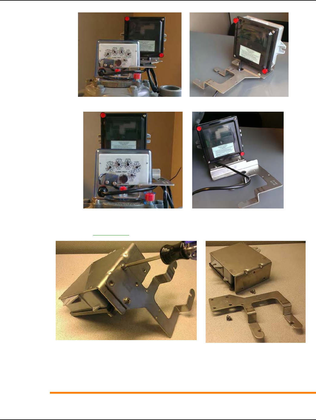
Figure 3 - 30. GPR at Left Rear - Using 28-1443 Bracket
Chapter 3 - American GPR Index Cover & GPR Install Landis+Gyr
44 98-1135 Rev AB Installation Guide
Figure 3 - 31. GPR at Right Rear - Using 28-1440 Bracket
Figure 3 - 32. GPR at C enter Rear - Using 28-1441Bracket
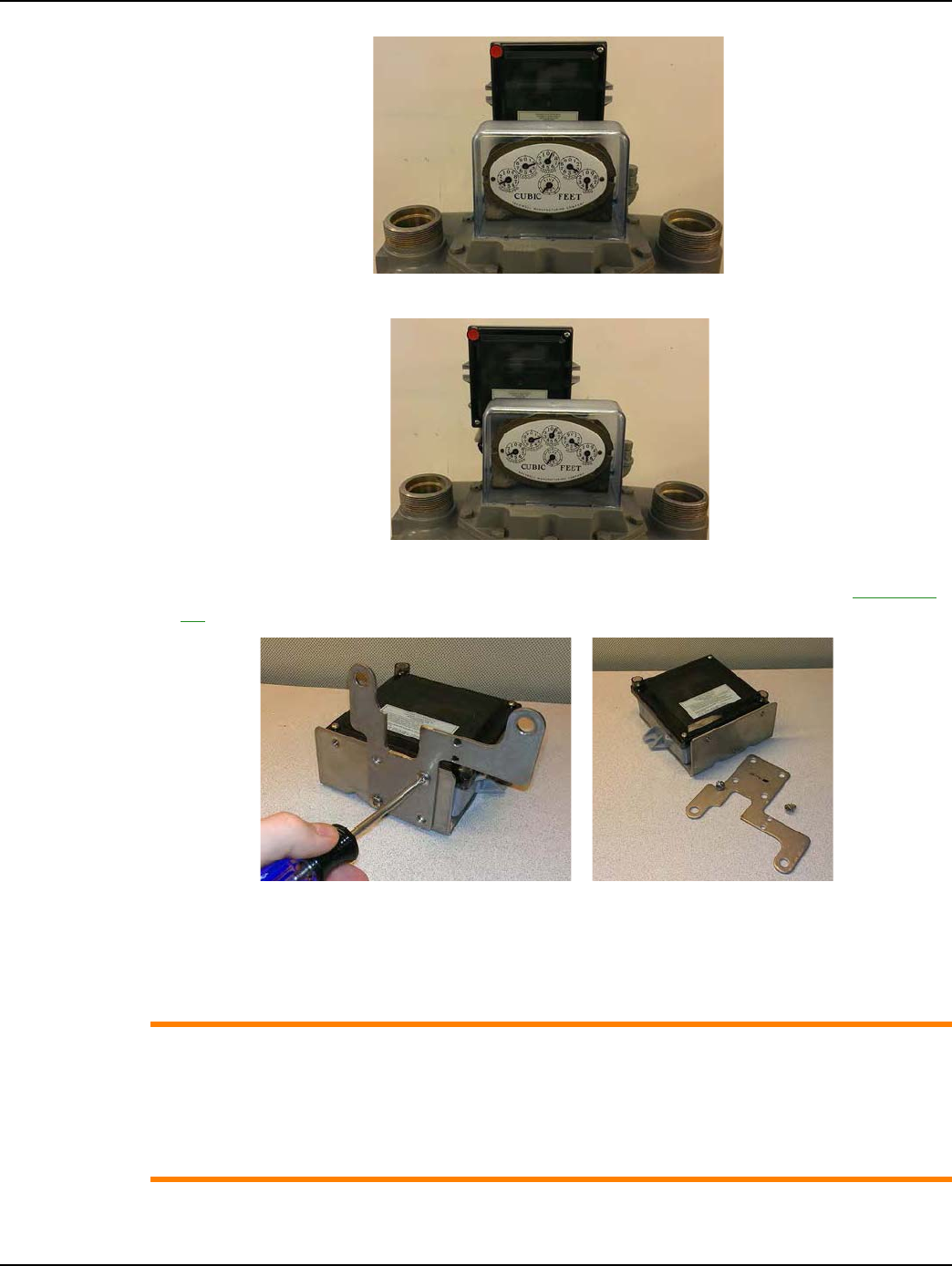
1. Lay the GPR face down. Remove the two screws and washers holding the two brackets together
as shown in Figure 3 - 33.
Figure 3 - 33. GPR Bracket Disassembly
2. Determine the appropriate GPR direction.
3. Install the two screws and lock washers. Tighten the screws to 30 inch-pounds (+/- 2 inch-
pounds).
ACAUTION: If the meter’s pipe route prevents installing the GPR as described in this manual,
the GPR may be mounted in a remote location away from the meter, such as on a wall or a

Landis+Gyr Chapter 3 - American GPR Index Cover & GPR Install
Installation Guide 98-1135 Rev AB 45
gas pipe. The maximum cable length between the Mini Switch and GPR must not exceed 200
feet.
ACAUTION: In a remote GPR Mounting environment, Pipe Bracket Kit 45-0080 may be used to
install the GPR on suitable plumbing pipes.

Chapter 3 - American GPR Index Cover & GPR Install Landis+Gyr
46 98-1135 Rev AB Installation Guide
4
Installation Guide 98-1135 Rev AB 47
Rockwell GPR Index Cover &
GPR Install
Rockwell Index Cover & Gas Module Removal
Meter Preparation
1. Remove the tamper seals, screws, and index cover assembly from the meter.
If there is no Commercial Gas Module connected to the meter, it will appear as below.
Figure 4 - 1. Rockwell Large Diaphragm Meter Index Cover Front And Rear Views
Figure 4 - 2. Remove Index Cover Tamper Seals, Screws. and Index Cover
2. If the meter has a Commercial Gas Module, perform the following steps.
A. Remove the index cover tamper seals.
B. Remove the module bracket fasteners and carefully disconnect the module and index cover
assembly from the meter.
Index Cover
Screws
Index Cover
Tamper Seals
Chapter 4 - Rockwell GPR Index Cover & GPR Install Landis+Gyr
48 98-1135 Rev AB Installation Guide
Figure 4 - 3. Center Dial and Offset Dial Mount Rockwell Commercial Index Covers
NOTE: There are two types of Rockwell Commercial index covers. Shown at left in Figure 4 - 3 is
the Center Dial Mount and at right is the Offset Dial Mount. Both types may be removed from the
meter in the same manner as shown in the next illustration.
Figure 4 - 4. Remove Module Bracket Tamper Seals, Screws, and Gas Module Assembly
3. Remove the 5/16-18 x 3/8-inch index frame screws and index mounting frame assembly from
the meter. Set the screws aside for later use.
ACAUTION: DO NOT remove the index from the mounting frame unless the frame or index is
damaged.
For proper meter operation, the frame screw tabs should be approximately 90 degrees
(perpendicular) to the upper portion of the frame containing the index.
Figure 4 - 5. Index Frame Screws and Frame Tabs
Landis+Gyr Chapter 4 - Rockwell GPR Index Cover & GPR Install
Installation Guide 98-1135 Rev AB 49
Figure 4 - 6. Commercial Module Cover Removed
4. Swipe each end of the module with an RF Buster or magnet to force the module to save meter
data to non-volatile memory. Remove the Commercial Gas Module tamper seals, screws, and
cover. Disconnect the battery.
5. The Commercial Gas Module must be disassociated from the meter.
A. If RIMS is used to manage gas module installations, leave the battery disconnected, replace
the module cover, and return the module to the Landis+Gyr cross-dock.
B. If GPrep is used to install the gas modules, connect the laptop PC and Shooter Box or USB
Shooter programming cable to the module Serial/Power connector. Follow the procedures
on using GPrep “MRB Mode” outlined in the “GPrep User Guide,” Landis+Gyr publication
98-1119.
6. Disconnect the module from the programming device. Leave the battery disconnected, replace
the module cover, and return the module to the Landis+Gyr cross-dock.
Rockwell Mini Switch Kit Installation
Meter Preparation
1. Inspect the index and replace it if any of the following conditions exists:
•Pointers are loose on their shafts.
•Index face contains cracked or peeling enamel.
•Index drive mechanism does not rotate easily.
NOTE: The GPR module gets readings from a dial wheel mounted on the vertical drive shaft behind
the index. The cover is installed on the meter with the sensor in the cover positioned on the BACK
side of the index.
Module Cover Tamper Seal
Location
Serial/Power
Connector
Chapter 4 - Rockwell GPR Index Cover & GPR Install Landis+Gyr
50 98-1135 Rev AB Installation Guide
Installing Back Mount Dial Wheels
Figure 4 - 7. Alignment Slots Top of Each Wheel Half
1. Insert one screw into the notched dial wheel half.
2. If the dial wheel halves have alignment slots, position them so that the slots on each half are
aligned. Turn the screw until it begins to thread into the threaded bottom wheel half as shown in
the following figures.
Figure 4 - 8. Notched Wheel Half with Screw Inserted
NOTE: For wheels WITHOUT alignment slots, there is no top or bottom, and there is no special
consideration regarding dial wheel assembly.
3. Slide threaded wheel half behind the rear vertical index drive shaft.
Figure 4 - 9. Place the Screw-bearing Notched Wheel Around the Index Drive Shaft
4. Rotate the notched wheel half in front of the shaft and insert the second screw.
5. Use a small Phillips-type screwdriver and turn each screw a few turns until they begin to thread
into the threaded wheel half.
6. Insert the 0.030 inch thick spacer shim between the dial wheel and the index top shaft support as
shown in the next figure.
Landis+Gyr Chapter 4 - Rockwell GPR Index Cover & GPR Install
Installation Guide 98-1135 Rev AB 51
Figure 4 - 10. Shim insertion
7. Press the dial wheel upward against the shim. The wheel must be held flush with the shim while
tightening the screws.
8. Tighten each screw a few turns at a time so that the two wheel halves remain parallel with each
other, keeping the dial wheel hole centered on the shaft. Tighten the screws to 3.5 inch-pounds ±
0.5 inch-pound).
UWARNING: To avoid damaging the dial wheel, take care not to overtighten the set screws.
9. Remove the shim. Verify that:
•the index shaft rotates freely
•the wheel does not wobble on the shaft or rub against the frame
Installing the Index
1. Install the index and frame assembly onto the meter.
2. Align the index drive shaft arm with the meter as shown in the next figure.
3. Using the 5/16-18 x 3/8” index frame screws that were set aside at the beginning of this
procedure, tighten the screws to 18 foot-pounds. ± 2 foot-pounds.
NOTE: For proper meter operation, the index frame screw tabs should be about 90 degrees
(perpendicular) to the upper portion of the frame containing the index.
Chapter 4 - Rockwell GPR Index Cover & GPR Install Landis+Gyr
52 98-1135 Rev AB Installation Guide
Figure 4 - 11. Index Drive Shaft Arm Alignment
If the index must be replaced or if the index has been removed from the frame, install the index
to the frame and tighten the 8-32 x 3/16 inch screws to 10.5 inch-pounds (± 1.5 inch-pound).
ACAUTION: The index MUST be installed with the mounting bracket inside the index back
plate, as shown in the following photograph.
Figure 4 - 12. Index Frame to Meter Head; Index to Index Frame Screws
4. Tighten the index frame to meter head screws to 18 foot-pounds (+/- 2 ft-lbs). Tighten the index
to index frame screws to 10.5 inch-pounds (± 1.5 inch-pounds).
Index Frame to Meter
Head Screws: 18 foot-
pounds
Index to Index
Frame Screws:
10.5 inch-pounds
Index
Mounting
Bracket
Index Back
Plate
Landis+Gyr Chapter 4 - Rockwell GPR Index Cover & GPR Install
Installation Guide 98-1135 Rev AB 53
GPR Direction
The GPR must face away from nearby walls and should be installed in a location unobstructed by
gas pipes. Refer to "Rockwell Changing GPR Orientation" on page -55 for instructions. Refer to
Appendix A, GPR Waterproofing for waterproofing guidelines before attaching connectors. Photos
are for reference only: GPR cover and battery should not be connected until Chapter 2.
UWARNING: The GPR and bracket must not interfere with access to the meter pressure tap.
There must be adequate room for connections to the pressure tap (refer to the following
photo).
Figure 4 - 13. Meter Pressure Tap
GPR Mounting
ACAUTION: Check the index cover switch cable assembly for nicks, abrasions, or any damage
prior to installing the assembly onto the meter.
1. Install the GPR bracket onto the index cover so that the bracket slot straddles the cable strain
relief as shown in Figure 4 - 14.
2. Use the two 5/16-18 x 1.25" screws and tamper cups provided in the parts kit to attach the GPR
bracket onto the index cover as shown in Figure 4 - 14. Tighten the screws to between 15 and 20
inch-pounds, as shown in Figure 4 - 15.
Figure 4 - 14. Install GPR Bracket, Screws and Tamper Cups
3. Install tamper seals into the tamper cups as shown in Figure 4 - 17 and Figure 4 - 16.
Chapter 4 - Rockwell GPR Index Cover & GPR Install Landis+Gyr
54 98-1135 Rev AB Installation Guide
Figure 4 - 15. Tighten Bracket Screws 15 to 20 inch-pounds
NOTE: Sensus (Rockwell/Equimeter) does not specify nor recommend a gasket between the index
cover and meter head. The meter parts list and assembly diagram do not include an index cover
gasket.
UWARNING: Take care not to pinch the index cover switch cable assembly in any way,
especially during the following installation steps:
during index cover and cable assembly installation onto the meter.
during GPR enclosure cover installation.
between the GPR and meter brackets and meter.
Figure 4 - 16. Coil Excess Cable
4. Coil the excess cable as shown in the photographs above.
5. Route the cable behind the index cover and dress it beneath the GPR bracket as shown in the
previous photo. Take care not to crimp the cable or pull the cable tight.
6. Secure the coiled cable to the GPR bracket with a black nylon zip tie.
Landis+Gyr Chapter 4 - Rockwell GPR Index Cover & GPR Install
Installation Guide 98-1135 Rev AB 55
Figure 4 - 17. Install a Seal In Each Tamper Cup
Figure 4 - 18. Attach Cable to Bracket with Black Zip Tie
Figure 4 - 19. GPR and Index Cover Installed in Both Orientations
Rockwell Changing GPR Orientation
The GPR must face away from nearby walls and toward the nearest MCC or Concentrator. The GPR
should be installed in a location unobstructed by gas pipes. Different mounting options are shown in
the following photographs. Choose mounting option before attaching battery and GPR cover.
Tamper Cup and
Seal
GPR Cable
Routed Beneath
GPR Bracket
Tamper Seal
Cable attached to
bracket with zip
tie
Chapter 4 - Rockwell GPR Index Cover & GPR Install Landis+Gyr
56 98-1135 Rev AB Installation Guide
Figure 4 - 20. GPR Facing Forward-Center
Figure 4 - 21. GPR Facing Forward-Left
1. Remove the two screws and washers holding the two brackets together as shown in Figure 4 -
22.
Figure 4 - 22. GPR Bracket Disassembly
2. Determine the appropriate GPR direction.
3. Install the two screws and lock washers. Tighten the screws to 30 inch-pounds (+0 / -2 inch-
pound).
ACAUTION: If the meter’s pipe route prevents installing the GPR as described in this manual,
the GPR may be mounted in a remote location away from the meter, such as on a wall or a
gas pipe. The maximum cable length between the Index Cover Assembly and GPR must not
exceed 200 feet.
In a remote GPR Mounting environment, Pipe Bracket Kit 45-0080 may be used to install the
GPR on suitable plumbing pipes. Remote GPR mounting is beyond the scope of this manual.
5
Installation Guide 98-1135 Rev AB 57
Schlumberger GPR Index
Cover & GPR Install
Schlumberger Index Cover & Gas Module Removal
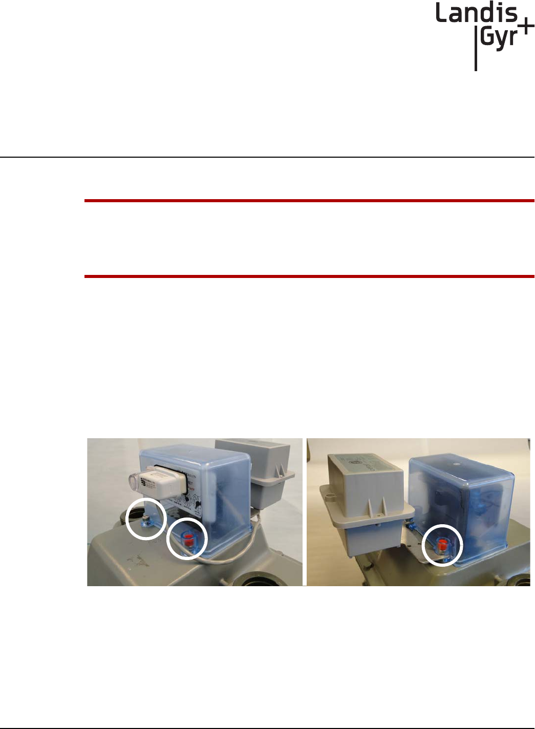
UWARNING: The Schlumberger/Actaris 675-1000 meter is designed so that the index may face
the front or rear of the meter. Landis+Gyr only supports GPR cover use when installed:
with the index facing the front of the meter
where the meter inlet pipe is located at the left side of the meter.
Meter Preparation
1. Remove the tamper seals, screws, and index cover assembly from the meter.
2. If the meter has a Landis+Gyr Commercial Gas Module, perform the following steps.
A. Remove the index cover tamper seals.
B. Remove the module bracket tamper seals.
C. Remove the module bracket fasteners and index cover screws.
D. Carefully disconnect the module and index cover assembly from the meter.
Figure 5 - 1. Front and Rear Views: Index Cover with Commercial Gas Module and Bracket
3. Two types of Schlumberger/Actaris 675 index mounting brackets may be encountered during
GPR Index Cover installations.
Tamper Seal
and Screw
Tamper Seal
and Screws
Chapter 5 - Schlumberger GPR Index Cover & GPR Install Landis+Gyr
58 98-1135 Rev AB Installation Guide
Index Mounting Bracket Types
Unsupported Mounting Bracket Assembly
The next three figures illustrate an example of an index mounting bracket assembly NOT supported
by the Schlumberger/Actaris GPR Index cover. This bracket assembly must be replaced with Itron
(Schlumberger/Actaris) part number 55045404.
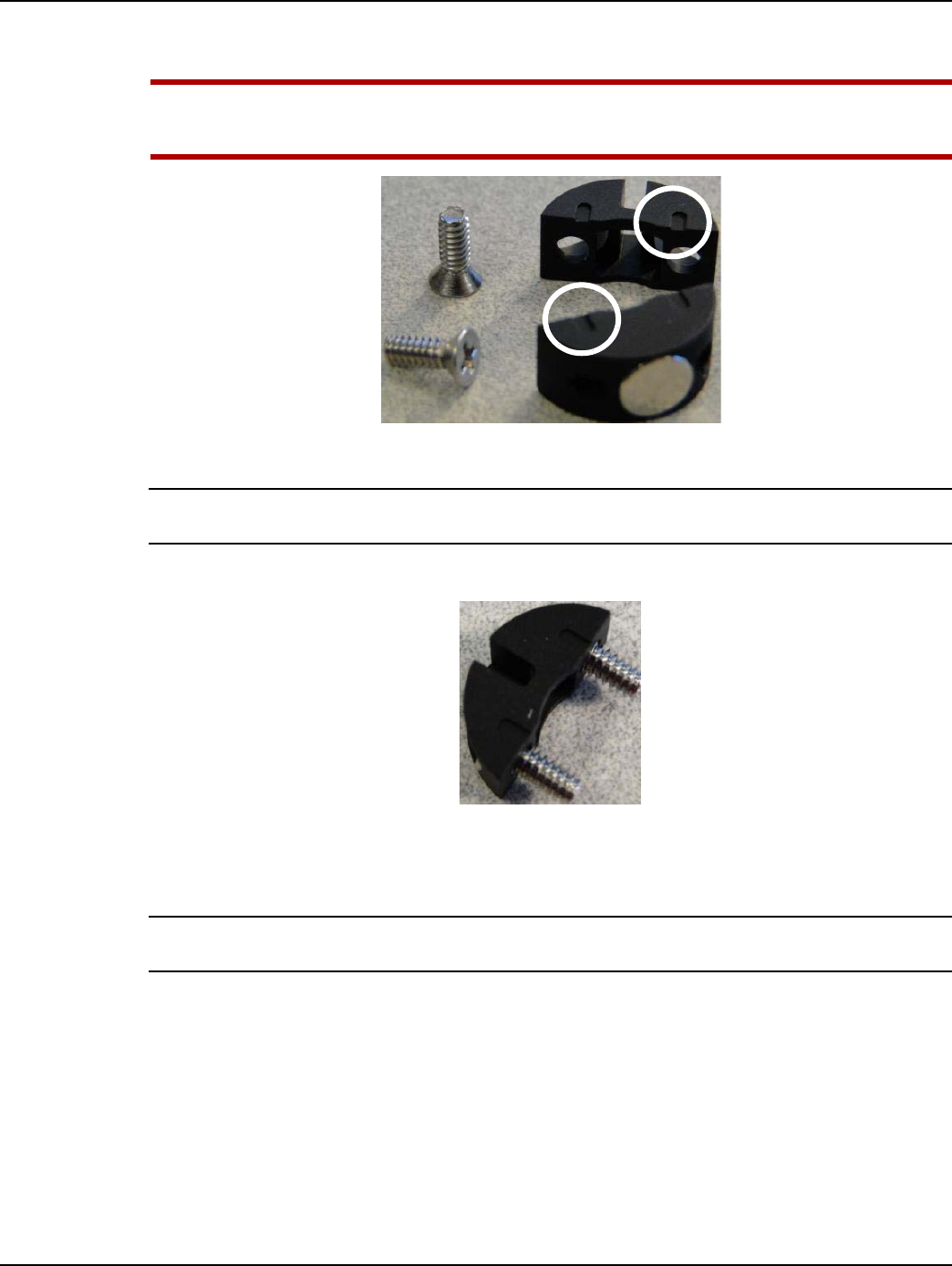
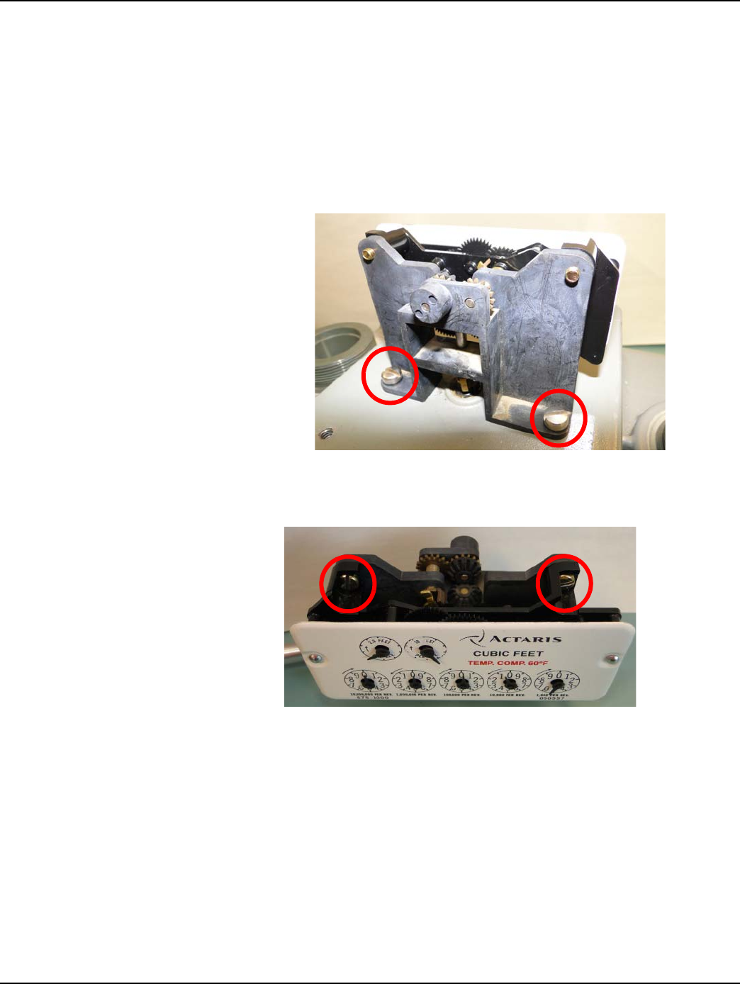
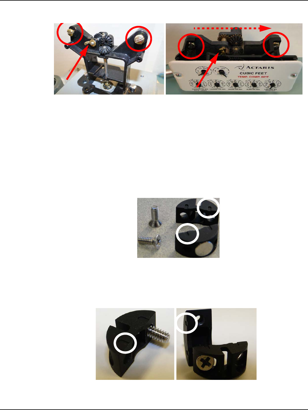
A. Remove the index mounting bracket assembly screws as shown in the following Figure (red
circles). Save the screws. They will be used again later.
Figure 5 - 2. Unsupported Index Mounting Bracket Assembly
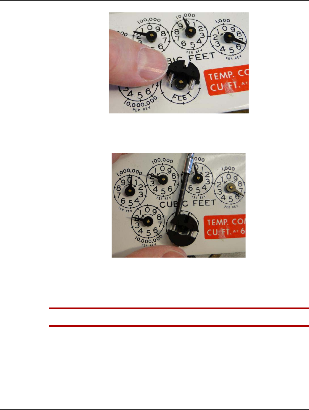
B. Remove the index screws and index from the mounting bracket as shown in the next two
figures. Save the screws. They will be used again later.
Figure 5 - 3. Remove Index and Screws; Discard the Unsupported Bracket Assembly
C. Indexes with part numbers 050556 and 050557, in good condition, should be set aside. They
may be used again later.
D. Discard the index mounting bracket assembly shown in Figure 5 - 4 and replace it with Itron
(Schlumberger/Actaris) part number 55045404 shown in Figure 5 - 5.
Remove and save
these screws
Remove the index and
screws; set the screws
aside for later use
Landis+Gyr Chapter 5 - Schlumberger GPR Index Cover & GPR Install
Installation Guide 98-1135 Rev AB 59
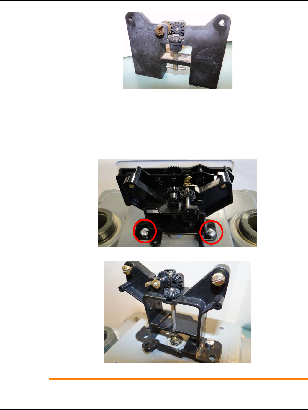
Figure 5 - 4. Index Removed from Unsupported Bracket Assembly
Supported Mounting Bracket Assembly
The index mounting bracket assembly shown in the next two figures, Itron (Schlumberger/Actaris)
part# 55045404, is supported with the GPR index cover.
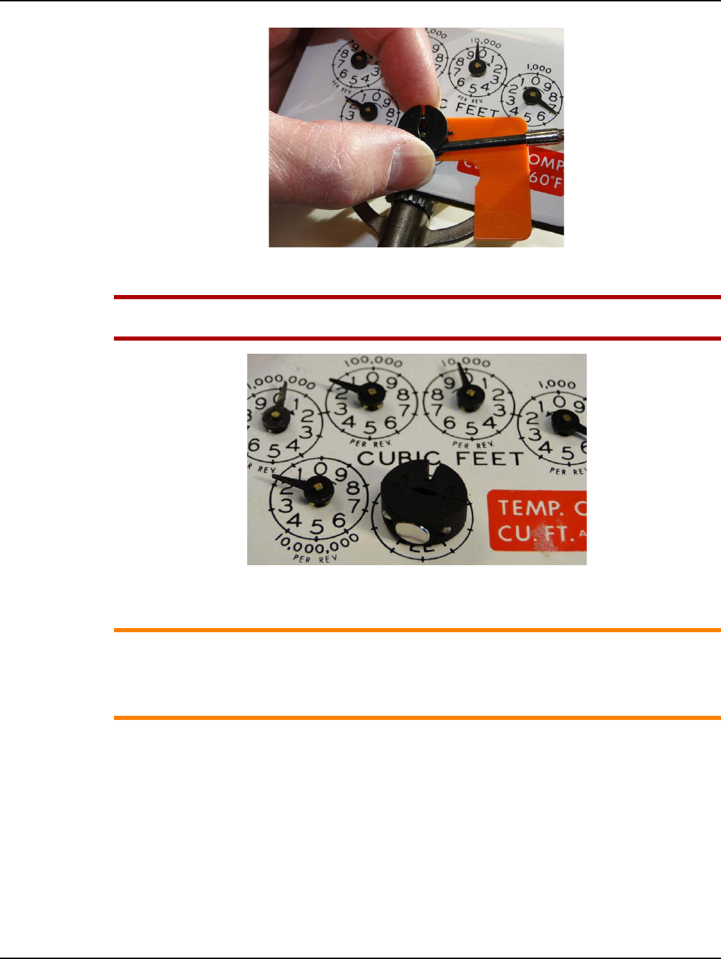
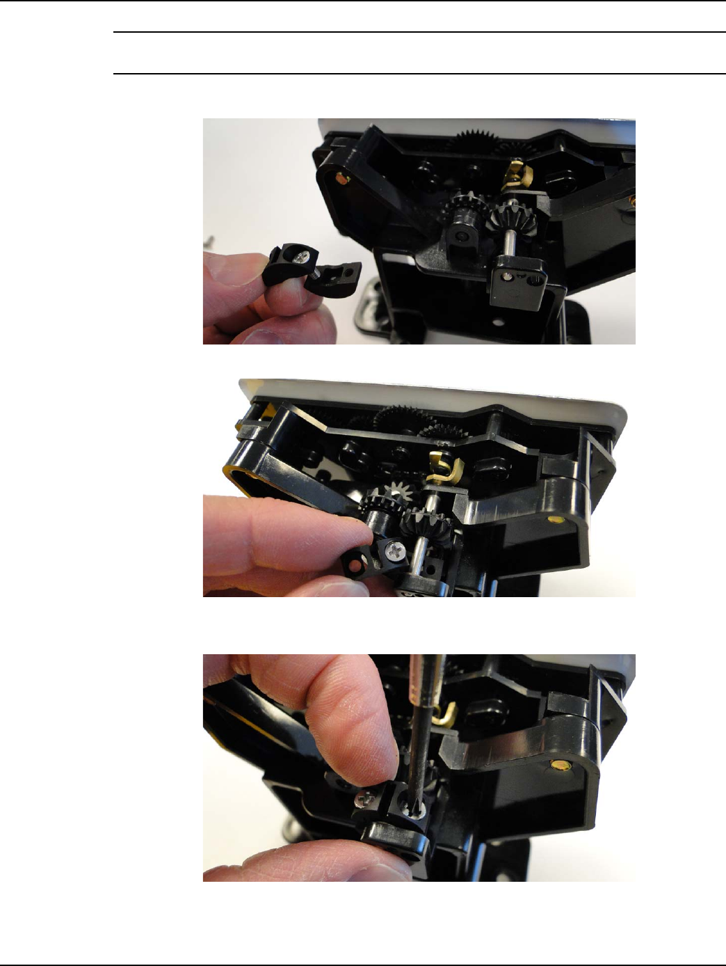
A. Remove the index mounting bracket assembly screws as shown in the following figure (red
circles). Save the index screws. They will be used during reassembly.
Figure 5 - 5. Rear View of Supported Index Mounting Bracket Assembly
Figure 5 - 6. Front View of Supported Index Bracket with Index Removed
ACAUTION: For illustrative purposes, the index has been removed from the mounting bracket
assembly in Figure 5 - 6. During on-site installations, DO NOT remove the index from this type
Chapter 5 - Schlumberger GPR Index Cover & GPR Install Landis+Gyr
60 98-1135 Rev AB Installation Guide
of mounting bracket unless the index is defective or damaged. See “Meter Preparation” on
page 57 for index approval criteria.
1. Remove the original gasket material from the meter. A scraper and wire brush may be required
to remove gasket material still adhering to meter mounting surfaces.
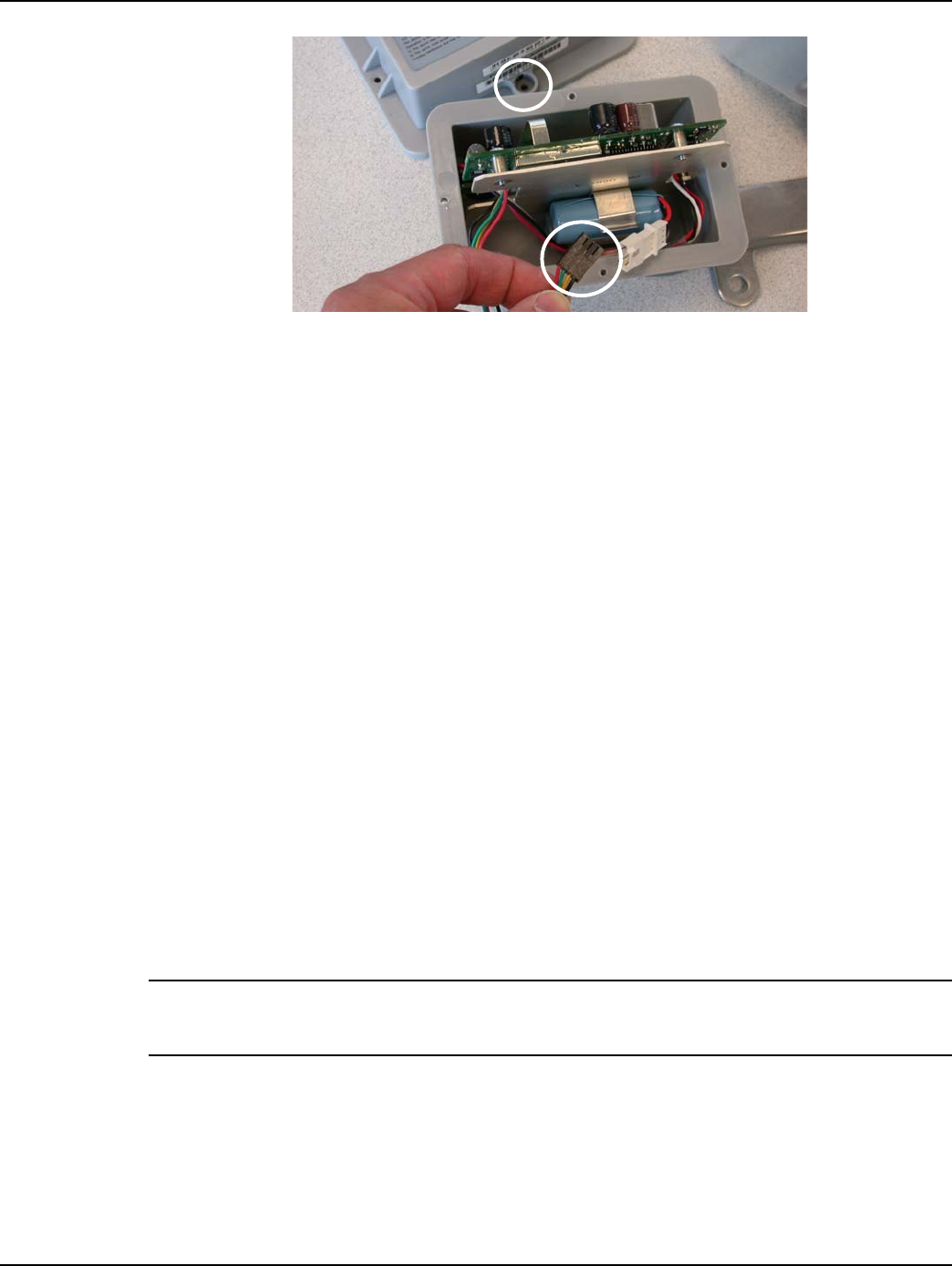
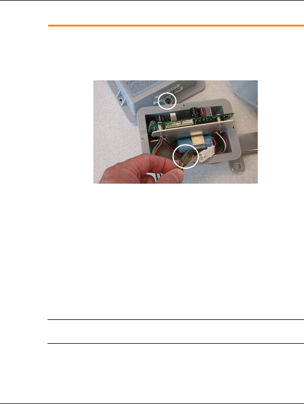
2. Swipe each end of the module with an RF Buster or magnet to force the module to save meter
data to non-volatile memory. Disconnect the battery.
3. Remove the Commercial Gas Module tamper seals, screws, and cover. Disconnect the battery
Figure 5 - 7. Disconnect Commercial Module Battery
4. The Commercial Gas Module must be disassociated from the meter.
A. If RIMS is used to manage gas module installations, leave the battery disconnected, replace
the module cover, and return the module to the Landis+Gyr cross-dock.
B. If GPREP is used to install the gas modules, connect the laptop PC and Shooter Box or USB
Shooter programming cable to the module Serial/Power connector. Follow the procedures
on using GPREP “MRB Mode” outlined in L+G document, “GPREP User Guide 98-1119.”
5. Disconnect the module from the programming device. Leave the battery disconnected, replace
the module cover, and return the module to the Landis+Gyr cross-dock.
Schlumberger Mini Switch Kit Installation
Meter Preparation
NOTE: The GPR assembly gets readings from a dial wheel mounted on the horizontal shaft behind
the index. The cover is installed on the meter with the sensor in the cover positioned on the back
side of the index.
Inspect the index and replace it if any of the following conditions exists:
•Pointers are loose on their shafts.
•Index face contains cracked or peeling enamel.
•Index drive mechanism does not rotate easily.
Cover Tamper Seal
Location
Serial/Power
Connector
Landis+Gyr Chapter 5 - Schlumberger GPR Index Cover & GPR Install
Installation Guide 98-1135 Rev AB 61
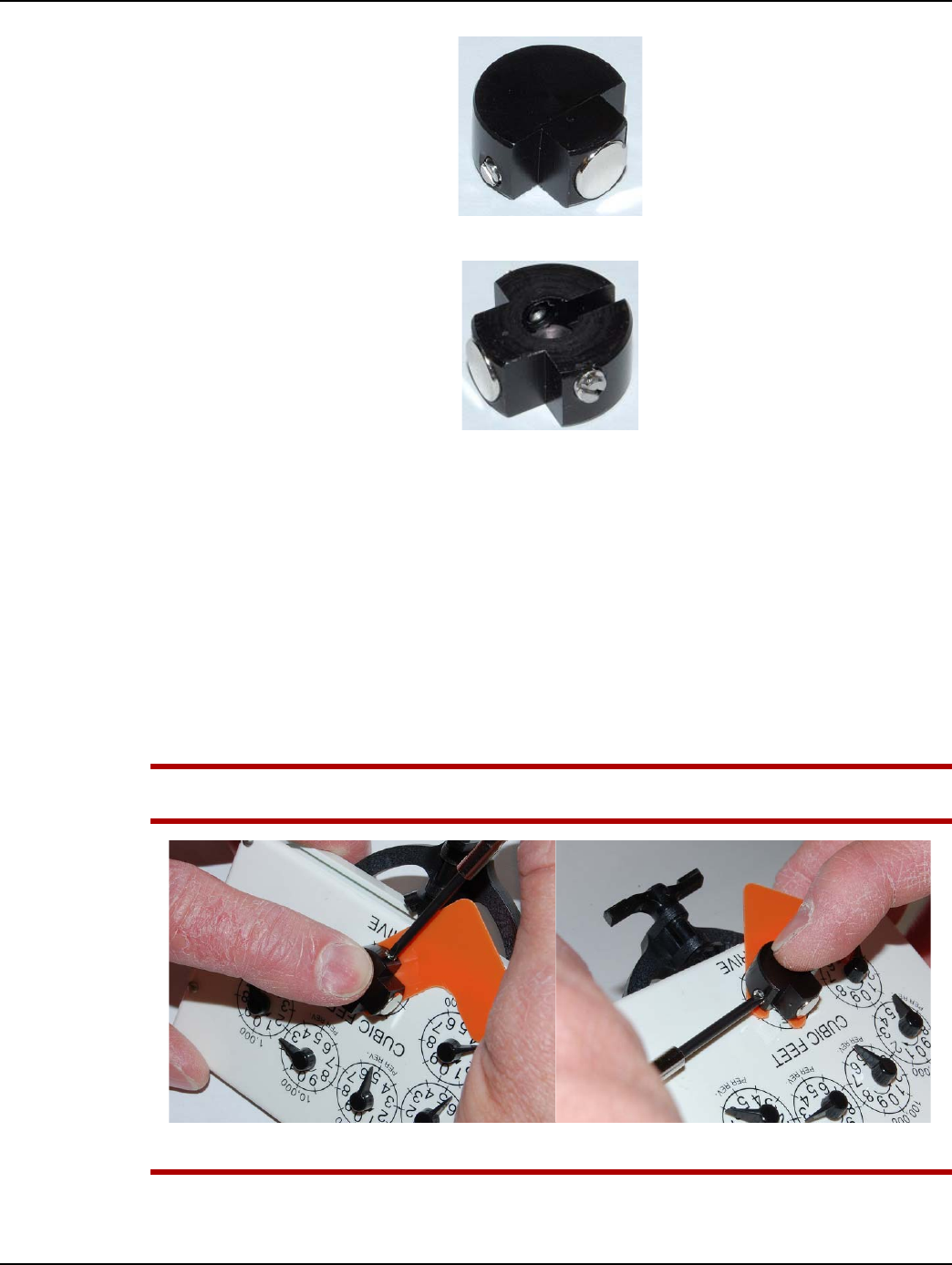
Perform the following steps if the index must be replaced:
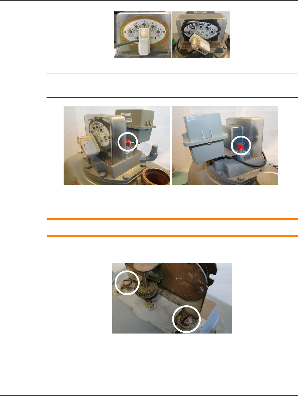
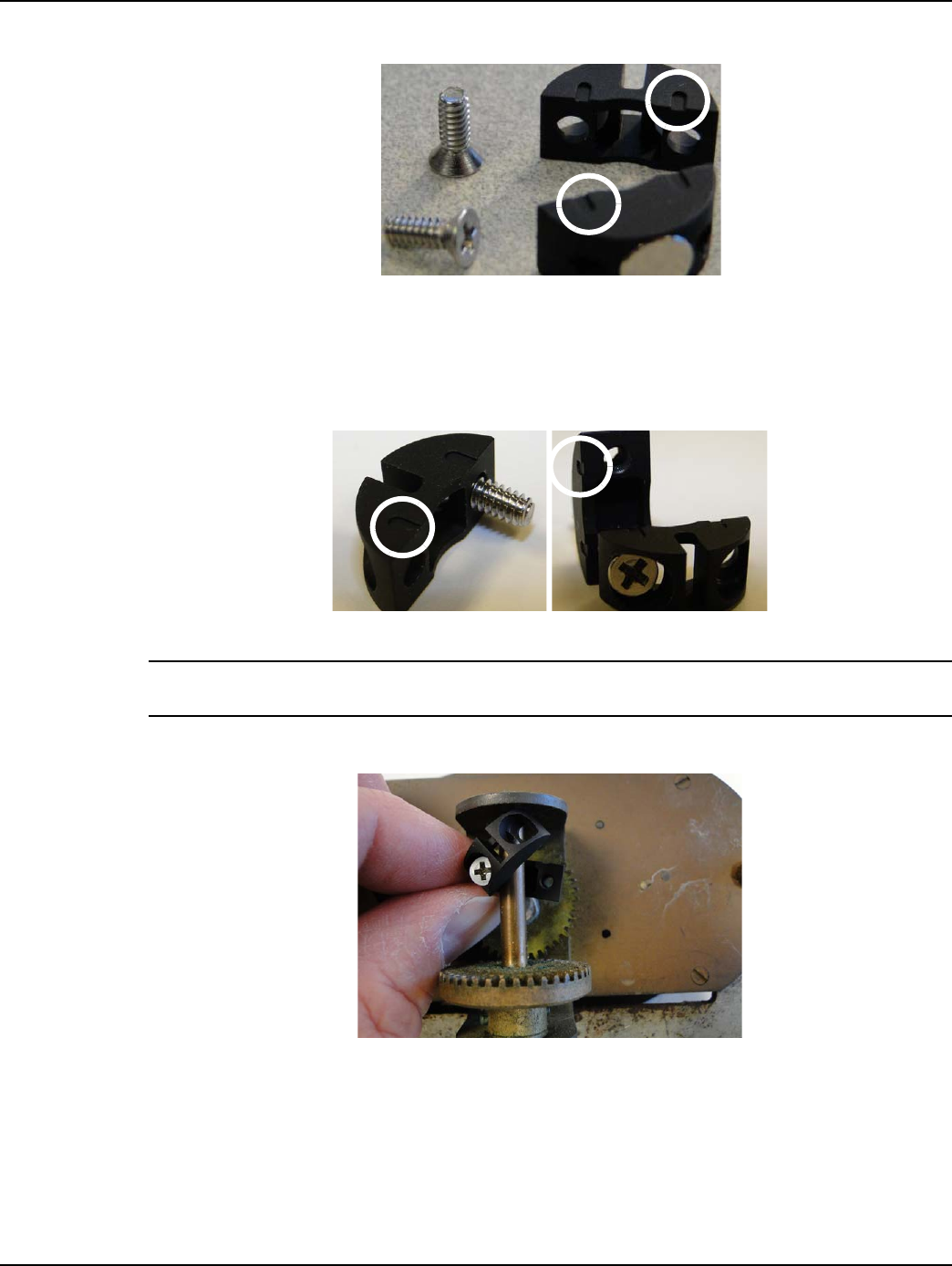
Figure 5 - 8. Index Screw and Drive Details
1. Turn index screws (shown by red circles) counter clockwise enough to loosen and gently slide
the old index screw tabs from beneath the screws using a right-to-left motion.
2. Slide the replacement index screw tabs beneath the screws using a left-to-right motion as shown
in the photo at right in Figure 5 - 8.
3. Verify that the index drive mechanisms of both the bracket and index (red arrows) are aligned
and free to rotate without binding.
4. Itron recommends tightening the screws “hand-tight” or 6 to 12 inch-pounds. The Itron
specification is listed as “3 to 6 inch-pounds (after relaxation)” in their published documents.
Installing Back Mount Dial Wheels
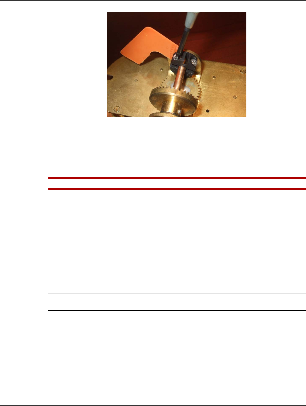
Figure 5 - 9. Alignment Slots On Top of Each Wheel Half
1. Insert one screw into the notched dial wheel half.
2. If the dial wheel halves have alignment slots, position them so that the slots on each half are
aligned. Turn the screw until it begins to thread into the threaded bottom wheel half as shown in
the following figures.
Figure 5 - 10. Alignment Slots Top of Each Wheel Half
Chapter 5 - Schlumberger GPR Index Cover & GPR Install Landis+Gyr
62 98-1135 Rev AB Installation Guide
NOTE: For wheels WITHOUT alignment slots, there is no top or bottom, and there is no special
consideration regarding dial wheel assembly.
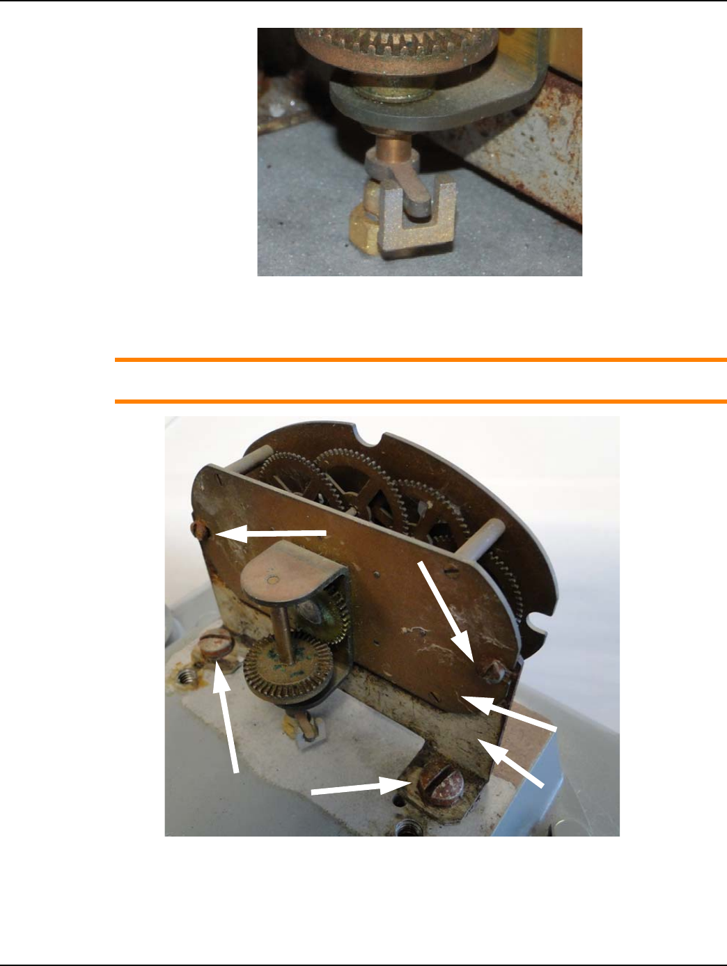
3. Slide threaded wheel half beneath the rear horizontal index drive shaft.
Figure 5 - 11. Slide Threaded Wheel Half Beneath the Index Drive Shaft
Figure 5 - 12. Slide Threaded Wheel Half Beneath Shaft
4. Rotate the notched wheel half over the top of the shaft and insert the second screw.
Figure 5 - 13. Turn Each Screw a Few Turns
5. Use a small Phillips-type screwdriver and turn each screw a few turns until they begin to thread
into the lower wheel half.
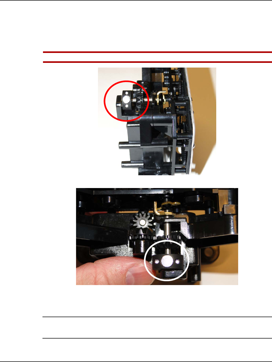
Landis+Gyr Chapter 5 - Schlumberger GPR Index Cover & GPR Install
Installation Guide 98-1135 Rev AB 63
6. Press wheel lightly but evenly against the shaft snap ring located at the rear of the shaft. The dial
wheel must not touch the gears on the shaft.
7. Tighten each screw a few turns at a time so that the two wheel halves remain parallel with each
other, and the dial wheel hole is centered on the shaft. Tighten the screws to 3.5 inch-pounds
± 0.50 inch-pounds.
UWARNING: Avoid damaging the dial wheel. Take care not to overtighten the set screws.
Figure 5 - 14. Dial Wheel on Shaft
Figure 5 - 15. Top View of Installed Dial Wheel
8. Install the index mounting bracket assembly onto the meter using the original screws. Tighten
the screws to 6 - 12 in-lb.
NOTE: The Schlumberger/Actaris 1000 meter is designed so that the index may face the front or
rear of the meter. Landis+Gyr only supports use of the GPR cover when installed with the index
facing the front of the meter where the meter inlet pipe is located at the left side of the meter.
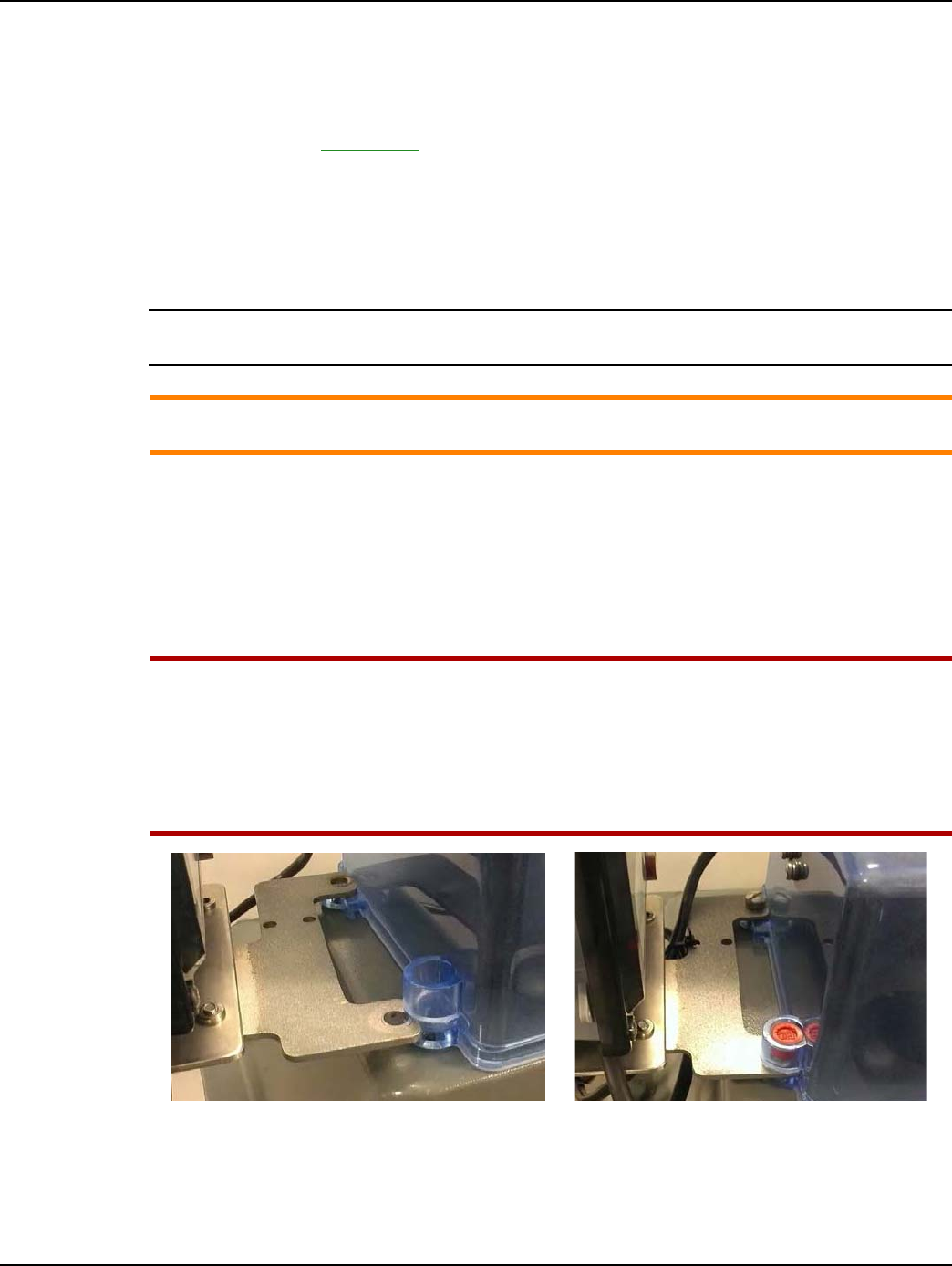
Chapter 5 - Schlumberger GPR Index Cover & GPR Install Landis+Gyr
64 98-1135 Rev AB Installation Guide
GPR Direction
If at all possible, the GPR must face away from nearby walls and should be installed in a location
unobstructed by gas pipes. Refer to "Schlumberger Changing GPR Orientation" on page -66 for
instructions. Refer to Appendix A, GPR Waterproofing for waterproofing guidelines before
attaching connectors. Photos are for reference only: GPR cover and battery should not be connected
until Chapter 2.
GPR Mounting
NOTE: The Schlumberger/Actaris GPR index cover comes with a silicone gasket. The installer is not
required to install a separate gasket.
ACAUTION: Check the index cover switch cable assembly for nicks, abrasions, or any damage
prior to installing the assembly onto the meter.
1. Install the GPR cover assembly as shown in the following photographs. The Solid State Switch
must be located at the rear of the index.
2. Insert two 1/4x20x5/8 inch screws provided in the parts kit into the index cover front screw
holes. Turn the screws clockwise until they begin to thread into the index cover mounting holes.
Do not tighten the screws.
3. Insert the GPR Bracket into the index cover rear tamper cup slot as shown below.
UWARNING: Take care not to pinch the index cover switch cable assembly in any way,
especially during the following installation steps:
During index cover and cable assembly installation onto the meter.
During GPR enclosure cover installation.
Between the GPR and meter brackets and meter.
Figure 5 - 16. Slide Bracket into Index Cover Tamper Cup Slot
4. Insert two 1/4x20x5/8 inch screws into the index cover rear screw holes. Tighten all index cover
screws to between 15 to 20 inch-pounds.
5. The cable may be routed above or below the mounting bracket as shown in the following photos.
Use the routing method that provides the best security and protection to the cable.
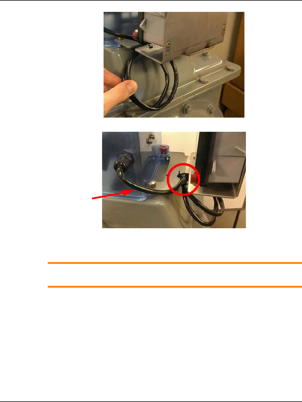
Landis+Gyr Chapter 5 - Schlumberger GPR Index Cover & GPR Install
Installation Guide 98-1135 Rev AB 65
Figure 5 - 17. Coil the Excess Cable
Figure 5 - 18. Route and Attach the Excess Cable
6. Attach the excess coiled cable to the GPR bracket with a black nylon zip tie as shown in the
previous figures.
ACAUTION: The cable should slope downward and away from the index cover to aid the water
tight strain relief in preventing water from entering the cover. Do NOT crimp or pull the cable
tight.
7. Insert tamper seals into the tamper cups.
Cable must slope
down and away
from cover
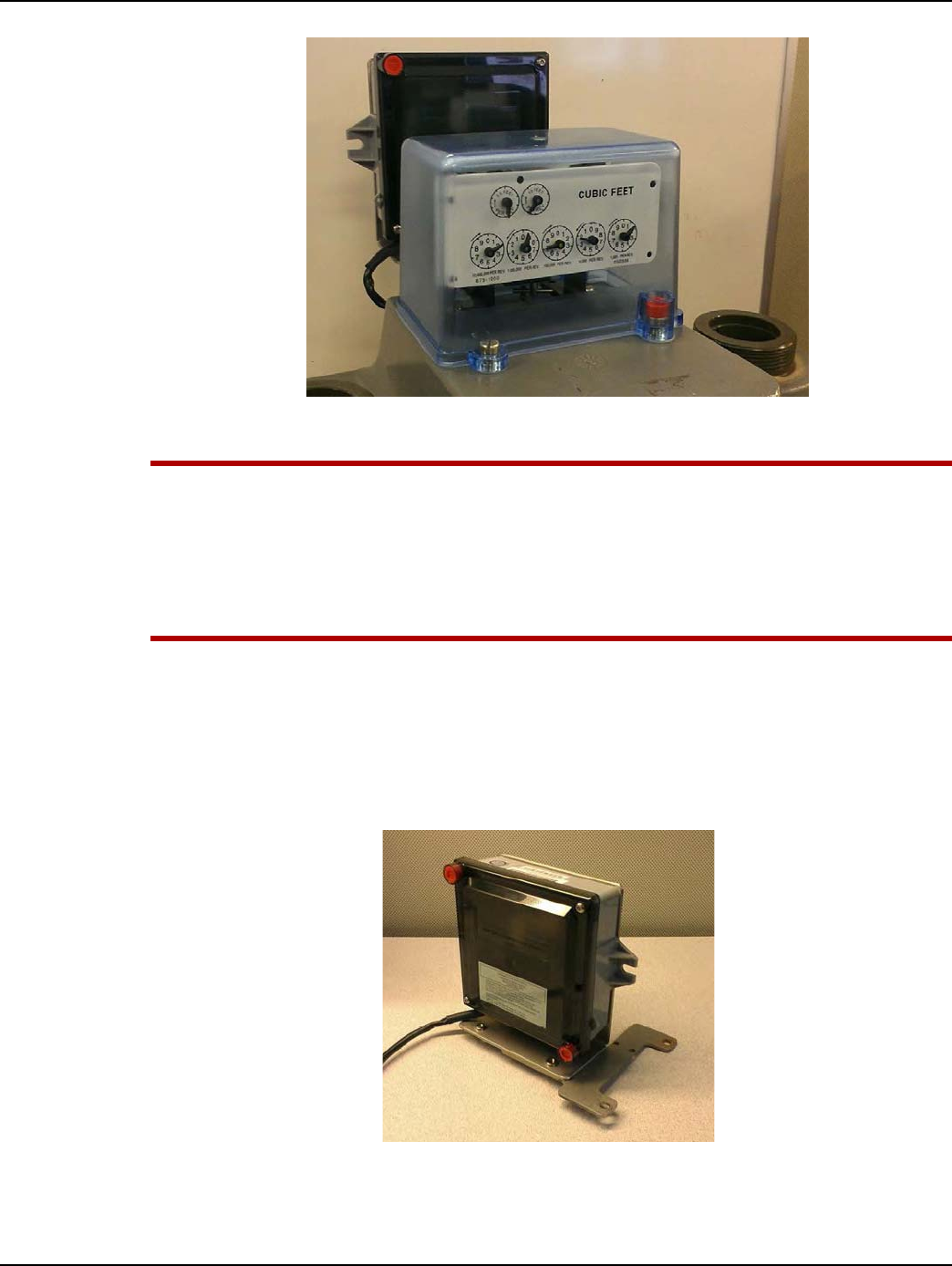
Chapter 5 - Schlumberger GPR Index Cover & GPR Install Landis+Gyr
66 98-1135 Rev AB Installation Guide
Figure 5 - 19. GPR and Index Cover Assembly Installed On a Schlumberger Large Diaphragm
Meter
UWARNING: The index cover switch cable assembly must not be pinched in any way,
especially under the following circumstances:
During index cover and cable assembly installation onto the meter.
During GPR enclosure cover installation.
Between the GPR and meter brackets and meter.
Schlumberger Changing GPR Orientation
The GPR must face away from nearby walls and toward the nearest MCC or Concentrator. The GPR
should be installed in a location unobstructed by gas pipes. Different mounting options are shown in
the following photographs. Choose mounting option before attaching battery and GPR cover.
Figure 5 - 20. GPR Facing Left
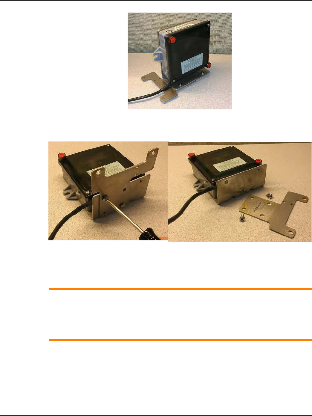
Landis+Gyr Chapter 5 - Schlumberger GPR Index Cover & GPR Install
Installation Guide 98-1135 Rev AB 67
Figure 5 - 21. GPR Facing Right
1. Lay the GPR on its back. Remove the two screws and washers holding the two brackets together
as shown in the next figure.
Figure 5 - 22. GPR Bracket Disassembly
2. Determine the appropriate GPR direction.
3. Install the two screws and lock washers. Tighten the screws to 30 inch-pounds (+ / - 2 inch-
pounds).
ACAUTION: If the meter’s pipe route prevents installing the GPR as described in this manual,
the GPR may be mounted in a remote location away from the meter, such as on a wall or a
gas pipe. The maximum cable length between the Index Cover Assembly and GPR must not
exceed 200 feet.
In a remote GPR Mounting environment, Pipe Bracket Kit 45-0080 may be used to install the
GPR on suitable plumbing pipes. Remote GPR mounting is beyond the scope of this manual.

Chapter 5 - Schlumberger GPR Index Cover & GPR Install Landis+Gyr
68 98-1135 Rev AB Installation Guide
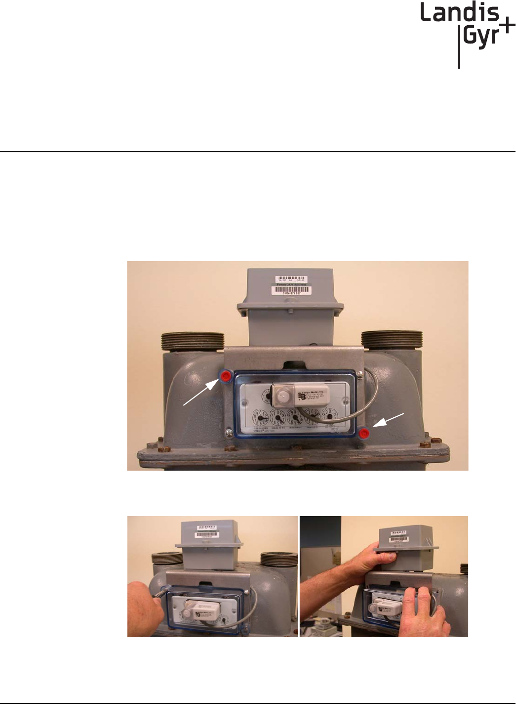
6
Installation Guide 98-1135 Rev AB 69
Sprague GPR Index Cover &
GPR Install
Sprague Index Cover & Gas Module Removal
Meter Preparation
1. Remove the tamper seals, screws, and index cover assembly from the meter.
2. If a Commercial Gas Module is present, remove the tamper seals and screws.
Figure 6 - 1. Sprague Large Diaphragm Meter with Commercial Gas Module
3. Remove the bracket and Index Cover assembly. Take care not to damage the meter index.
Figure 6 - 2. Remove Tamper Seals and Screws – Carefully Remove Module & Bracket Assembly
Tamper Seal
Tamper Seal
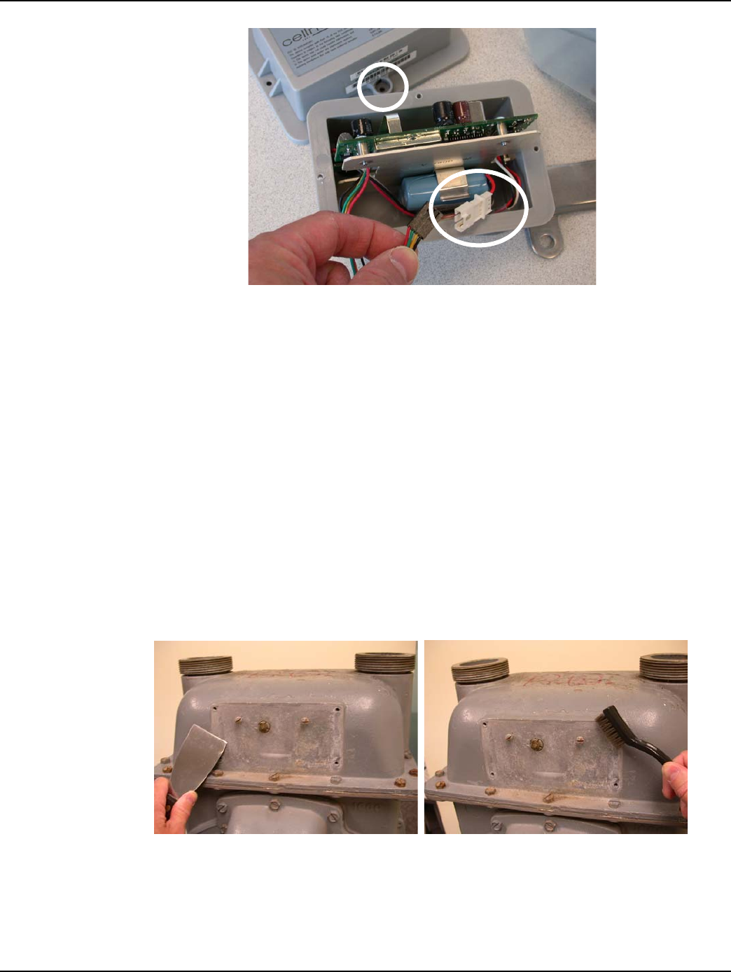
Chapter 6 - Sprague GPR Index Cover & GPR Install Landis+Gyr
70 98-1135 Rev AB Installation Guide
Figure 6 - 3. Commercial Module Cover Removed
4. Swipe each end of the module with an RF Buster or magnet to force the module to save meter
data to non-volatile memory. Remove the Commercial Gas Module tamper seals, screws, and
cover. Disconnect the battery.
5. The Commercial Gas Module must be disassociated from the meter.
A. If RIMS is used to manage gas module installations, leave the battery disconnected, replace
the module cover, and return module to the Landis+Gyr cross-dock.
B. If GPrep is used to install gas modules, connect the laptop PC and Shooter Box or USB
Shooter programming cable to the module Serial/Power connector.
Follow the procedures on using GPrep “MRB Mode” outlined in Landis+Gyr document
“GPrep User Guide 98-1119.”
6. Disconnect the module from the programming device. Leave the battery disconnected, replace
the module cover, and return the module to the Landis+Gyr cross-dock.
7. Remove all of the original gasket material from the meter. Clean the gasket surface of the meter
with a wire brush and a gasket scraper. The index may need to be removed during gasket
removal to prevent damage and avoid gasket material entering the index gears.
Figure 6 - 4. Removing Old Gasket Material with a Scraper and a Wire Brush
8. Inspect the index. Replace it if:
•index pointers are loose on their shafts
•the index face contains cracked or peeling enamel
•Index drive mechanism does not rotate easily
Cover Tamper Seal Location
Serial/Power Connector
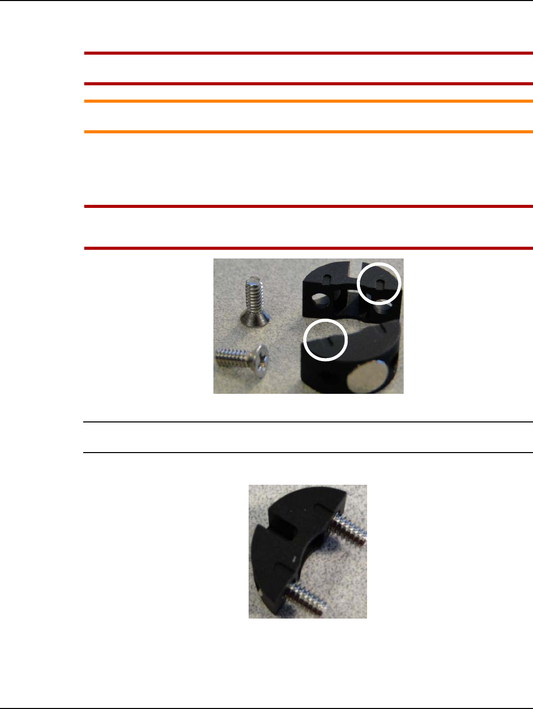
Landis+Gyr Chapter 6 - Sprague GPR Index Cover & GPR Install
Installation Guide 98-1135 Rev AB 71
Sprague Mini Switch Kit Installation
UWARNING: The Front mount dial wheel must be used with metal pointer indexes.
The Balanced Dial wheel must be used on plastic pointer indexes.
ACAUTION: Take care not to over-tighten the set screws to avoid damaging the index pointer
and dial wheel.
Installing Front Mount Dial Wheels on Metal Pointer Indexes
1. Remove the index from the meter. Place the screws aside for re-use at the end of this process.
UWARNING: To maintain proper clearance, the Front mount dial wheel must be installed so
that, if alignment slots are present, the alignment slots on each wheel half are on top as
shown in Figure 6 - 5.
Figure 6 - 5. Alignment Slots Top of Each Wheel Half
NOTE: For wheels WITHOUT alignment slots, the dial wheel has no top or bottom, and there is no
special consideration regarding dial wheel assembly.
2. Insert screws into the notched dial wheel half.
Figure 6 - 6. Notched Wheel Half with Screws Inserted
3. Rotate the index drive mechanism so that the metal proving/test pointer is in an upward
direction.
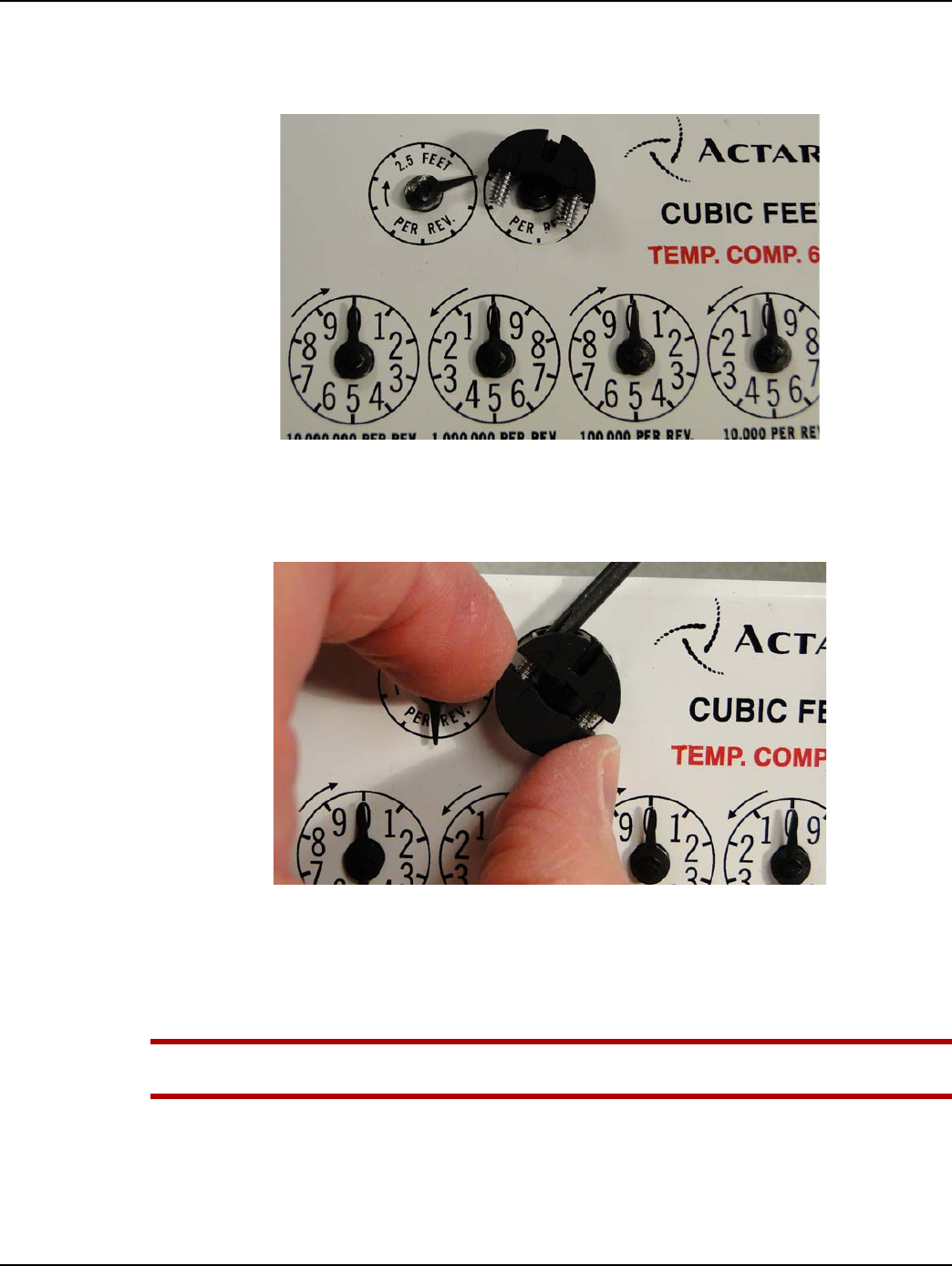
Chapter 6 - Sprague GPR Index Cover & GPR Install Landis+Gyr
72 98-1135 Rev AB Installation Guide
4. Position the screw-bearing notched wheel half for installation by sliding it downward over the
index proving/test pointer tip as shown in Figure 6 - 7. If present, the two alignment slots and
pointer notch must be visible on top of the wheel half.
Figure 6 - 7. Slide Screw-bearing Notched Wheel Half over Index Proving/Test Pointer Tip
5. Position the threaded wheel half against the rounded end of the index pointer. Use a small
Phillips-type screwdriver and turn each screw a few turns until they begin to thread into the
threaded wheel half. Do not tighten the screws.
Figure 6 - 8. Thread Screws Into threaded Wheel Half
6. Insert the 0.030 inch thick spacer shim beneath the Front mount dial wheel as shown in Figure 6
- 9. Hold the dial wheel as shown. Tighten each screw a few turns at a time so that the two wheel
halves remain parallel with each other. Tighten the screws to 1.2 ± 0.1 inch-lbs. Remove the
spacer shim.
UWARNING: The main index drive shaft must remain free to rotate while the wheel screws are
tightened to prevent damage to the index pointer and pointer shaft.
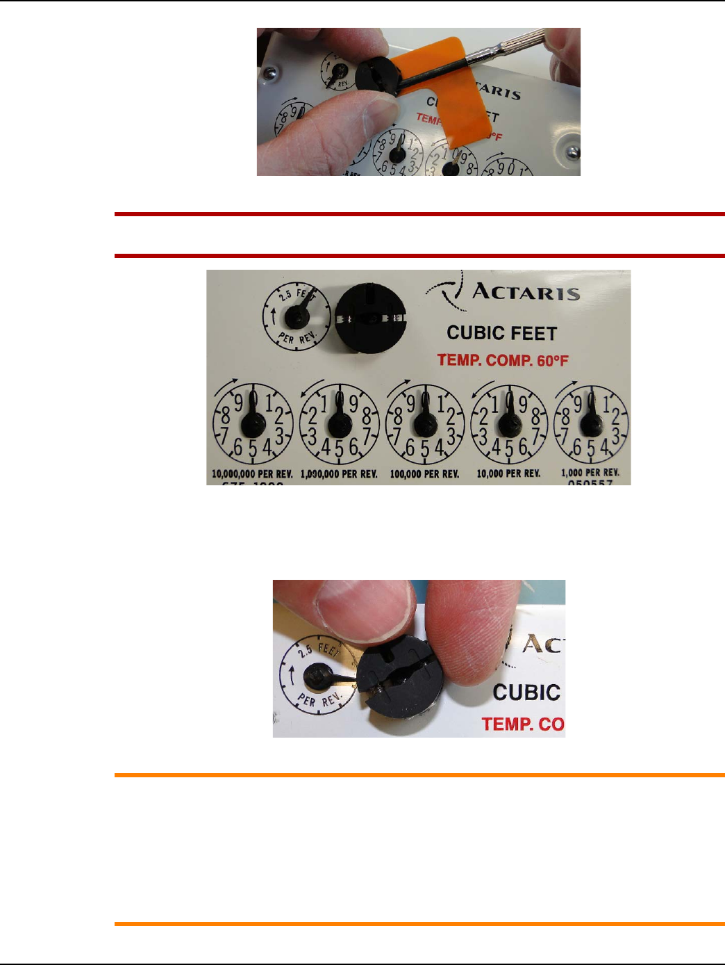
Landis+Gyr Chapter 6 - Sprague GPR Index Cover & GPR Install
Installation Guide 98-1135 Rev AB 73
Figure 6 - 9. Insert Shim and Alternately Tighten Screws To 1.2 inch-lbs. (±0.10 inch-lbs.)
UWARNING: To avoid damaging the index pointer and dial wheels, take care not to over-
tighten the set screws.
Figure 6 - 10. Front Mount Dial Wheel Installed
7. Verify that the dial wheel rotates freely without rubbing the index surface. Rotate the wheel
several times as shown in the next figure to verify that the wheel does NOT contact adjacent
index pointers.
Figure 6 - 11. Dial Wheel Must Not Contact Adjacent Pointers As It Rotates
ACAUTION: The installed dial wheel shall not move from the installed position, and cannot
physically contact the index face or other pointers on the index.
If contact occurs, Landis+Gyr recommends replacing the metal pointer index with an index
using plastic pointers so that the Balanced Dial Wheel can be used.
If dial wheel contact with the adjacent proving pointer tip is unavoidable, 1/4 of the adjacent
proving pointer tip may be removed with diagonal cutters, but only with permission from the
utility customer.
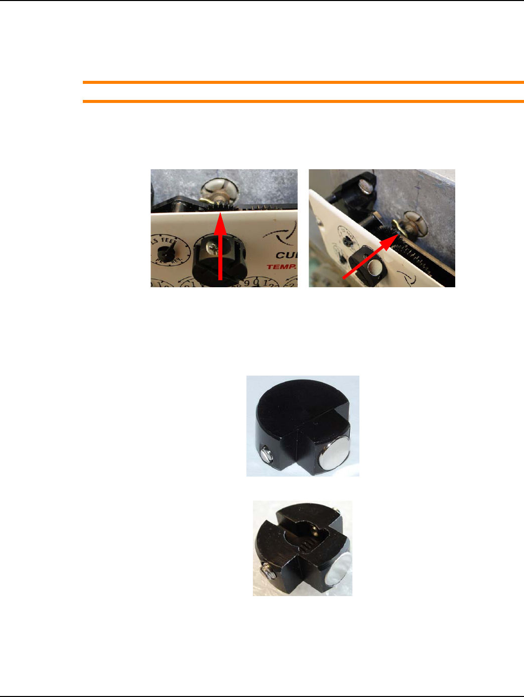
Chapter 6 - Sprague GPR Index Cover & GPR Install Landis+Gyr
74 98-1135 Rev AB Installation Guide
8. Install the index onto the meter using the original screws that were placed aside in the first step
of this process. If the index has a brass mounting bracket, tighten the index screws to a torque
value of 6 - 12 inch-pounds. If the index uses a plastic mounting bracket, tighten the index
screws to a torque value of 15 - 20 inch-pounds.
ACAUTION: Use caution when tightening the index screws to prevent damage to the index.
9. Confirm that the index’s center of rotation is aligned with the meter dog’s center of rotation.
Adjust the index alignment as needed. The magnet wheel center of rotation must be aligned
with the meter index drive mechanism center of rotation, shown by RED ARROWS in the
following photos.
Figure 6 - 12. Wheel Center Of Rotation Must Align With Meter Drive Center Of Rotation
Installing Balanced Dial Wheels on Plastic Pointer Indexes
1. Using a small flat blade screw driver, turn each screw counter-clockwise until the tip of each
screw is flush with the inner surface of the wheel.
Figure 6 - 13. Top View - Balanced Dial Wheel
Figure 6 - 14. Bottom View - Balanced Dial Wheel
2. Position the Balanced dial wheel over the plastic index proving/test pointer as shown in the
following figures. The bottom of the dial wheel is slotted so that it may only be installed with the
slot in the same direction as the index pointer.
3. Insert the 0.030 inch thick shim beneath the dial wheel.
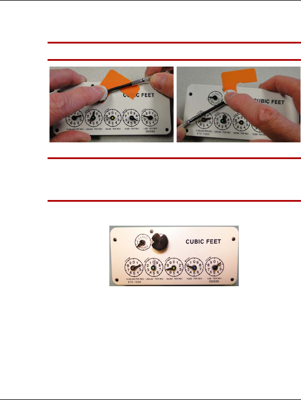
Landis+Gyr Chapter 6 - Sprague GPR Index Cover & GPR Install
Installation Guide 98-1135 Rev AB 75
4. Gently press the wheel against the shim with your index finger or thumb. The dial wheel must be
level with the surface of the index.
5. Evenly tighten each screw to 1.2 ± 0.10 inch-pounds.
UWARNING: The main index drive shaft must remain free to rotate as the wheel screws are
tightened to prevent damage to the index pointer and pointer shaft
Figure 6 - 15. Tighten Dial Wheel Screws to 1.2 ± 0.10 Inch-Pounds
UWARNING: Take care not to over-tighten the set screws to avoid damaging the index pointer
and dial wheel.
The installed dial wheel shall not move from the installed position, and cannot physically
contact the index face or other pointers on the index. If contact occurs, the index should be
replaced with an approved index.
6. Remove the shim and verify that the wheel rotates freely while remaining level with the index
surface.
Figure 6 - 16. Balanced Dial Wheel Installed
7. Install the index onto the meter using the original screws. The meter's drive dog must be inserted
into a groove on the index drive mechanism as shown in Figure 6 - 17.
8. Confirm that the index’s center of rotation is aligned with the meter dog’s center of rotation.
Adjust the index alignment as needed. The magnet wheel center of rotation must be aligned
with the meter index drive mechanism center of rotation, shown by RED ARROWS in the
following photos. Tighten the index screws to a torque of 15 - 20 inch-pounds.
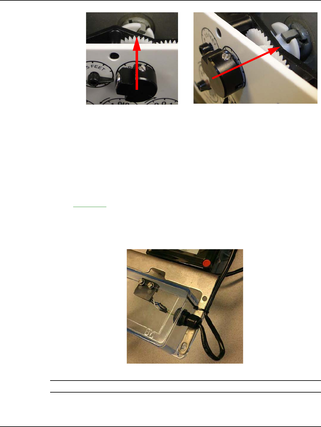
Chapter 6 - Sprague GPR Index Cover & GPR Install Landis+Gyr
76 98-1135 Rev AB Installation Guide
Figure 6 - 17. Wheel Center Of Rotation Must Align With Meter Drive Center Of Rotation
GPR Direction
Before performing the following steps, determine the direction that the GPR will face. The GPR
must face away from nearby walls and should be installed in a location unobstructed by gas pipes.
Refer to "Sprague Changing GPR Orientation" on page -80 for instructions.
GPR Mounting
Refer to Appendix A, GPR Waterproofing for waterproofing guidelines before attaching connectors.
Photos are for reference only: GPR cover and battery should not be connected until Chapter 2.
1. Bend about three inches of cable into a loop and attach the cable to the bracket with a nylon zip
tie as shown in the following figure. Do not bend the cable so much as to crimp it. This provides
additional security for the cable and serves as a drip loop.
Figure 6 - 18. Switch Cover and GPR Assembly, with drip loop
NOTE: The cable strain relief is water tight and does not require a drip loop
2. Position the GPR bracket assembly over the cover edges as shown in Figure 6 - 18.
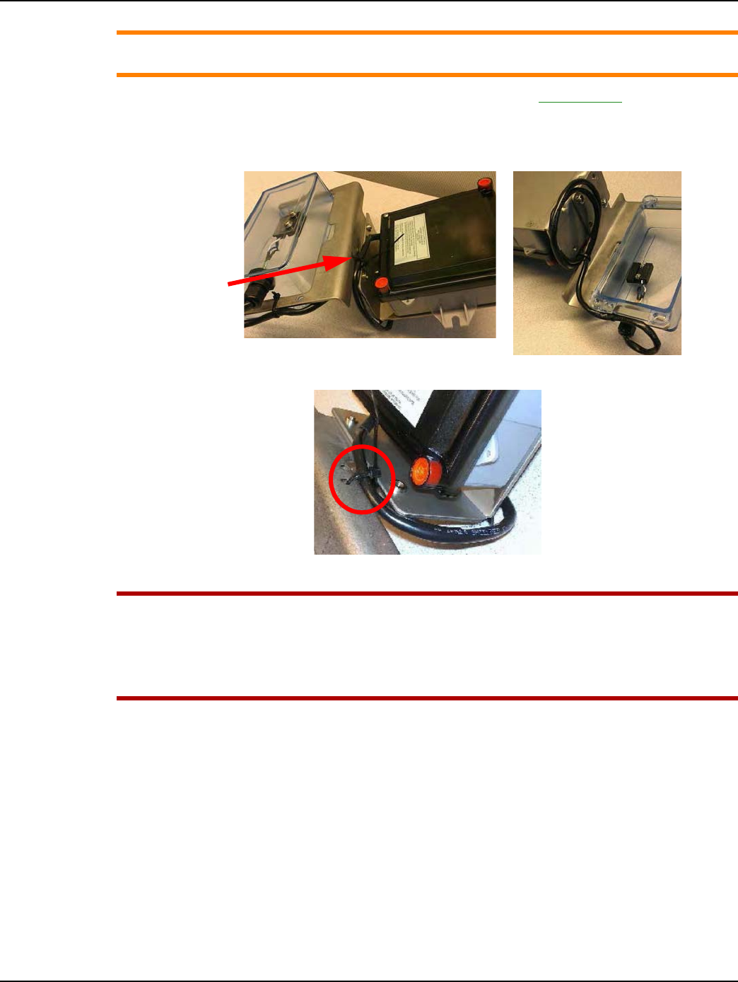
Landis+Gyr Chapter 6 - Sprague GPR Index Cover & GPR Install
Installation Guide 98-1135 Rev AB 77
ACAUTION: Check the index cover switch cable assembly for nicks, abrasions, or any damage
prior to installing the assembly onto the meter.
3. Coil the excess cable and route it behind the bracket as shown in Figure 6 - 19. Position the cable
behind the bracket and secure the cable to the bracket immediately below the GPR housing with
a black nylon zip tie. Do not completely tighten the zip tie. The cable must remain free to move
until the GPR has been installed on the meter.
Figure 6 - 19. Excess Coiled Cable Attached Beneath GPR Bracket
Figure 6 - 20. Excess Coiled Cable Attached Beneath GPR Bracket
UWARNING: Take care not to pinch the index cover switch cable assembly in any way,
especially during the following installation steps:
During index cover and cable assembly installation onto the meter.
During GPR enclosure cover installation.
Between the GPR and meter brackets and meter.
4. Install the GPR index cover and GPR assembly over the meter dial index as shown in the next
figure. The cover must be installed with the 1/8 inch thick cork gasket provided with the GPR
index kit.
Loosely
secure the
excess cable
to the bracket
with a black
zip tie
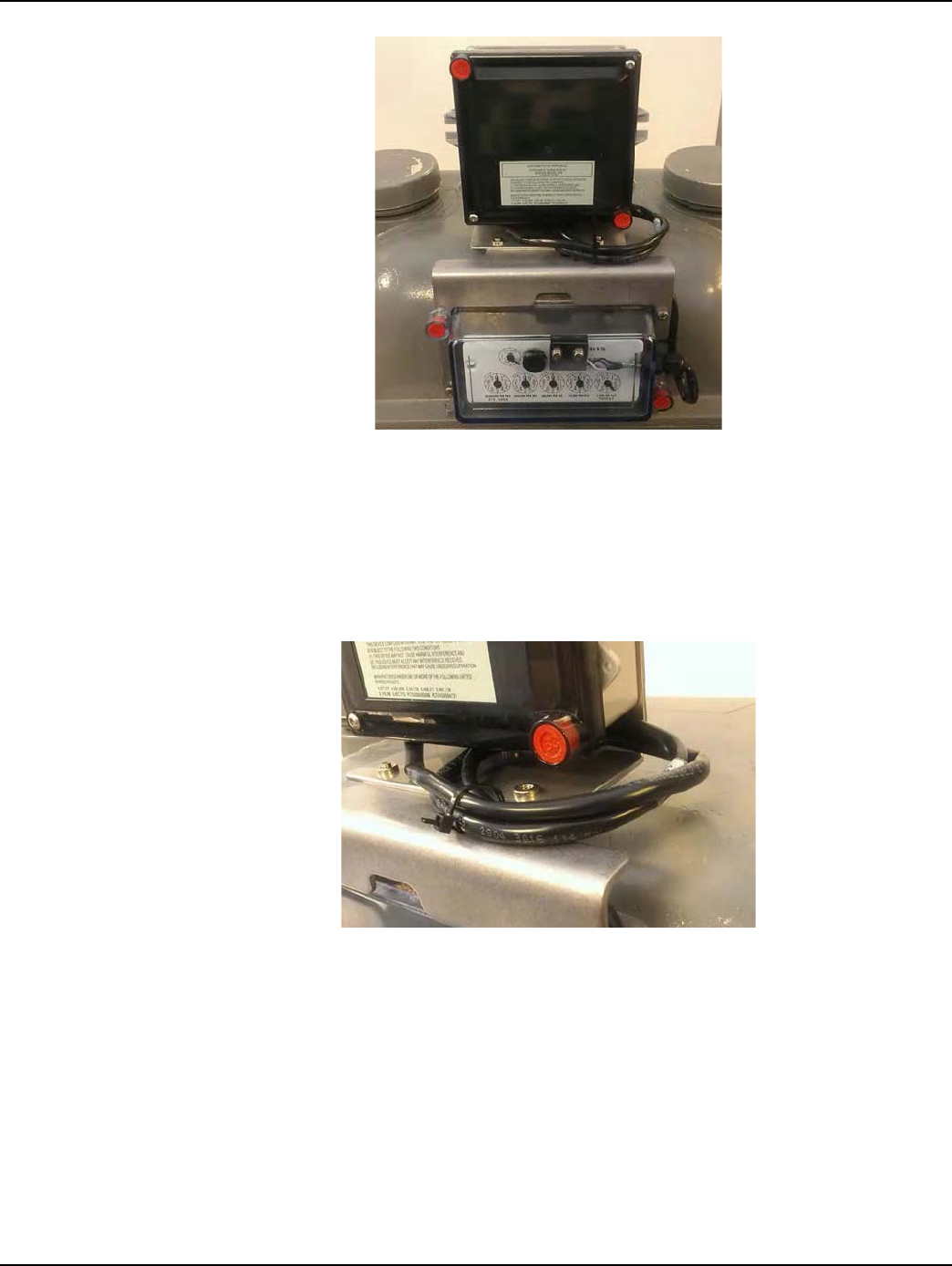
Chapter 6 - Sprague GPR Index Cover & GPR Install Landis+Gyr
78 98-1135 Rev AB Installation Guide
Figure 6 - 21. Switch Wires Must Not Interfere With Index Pointers
5. Route the cable between the GPR bracket and top of the meter so that the cable has minimal
slack protruding from behind the bracket. Verify that the cable is not pinched between the
bracket and meter.
If the cable will not fit beneath the GPR bracket, or if the cable is subject to pinching or abrasion
between bracket and meter, attach the excess coiled cable to the top of the index cover bracket,
immediately below the GPR as shown in the next figure.
Figure 6 - 22. Cable Optionally Routed Above Index Cover Bracket
6. Tighten the nylon zip tie so that the cable is snug against the bracket. Cut away excess tie length.
7. Install the two 10-24 x 3/4 inch index cover screws with flat washers. Install one at lower left
and the other at upper right. Do not tighten these screws.
8. Install two tamper cups, plastic washers, and 10-24 x 7/8 inch screws in the remaining cover
holes. Tighten all four cover screws to a torque value of 20 inch-pounds.
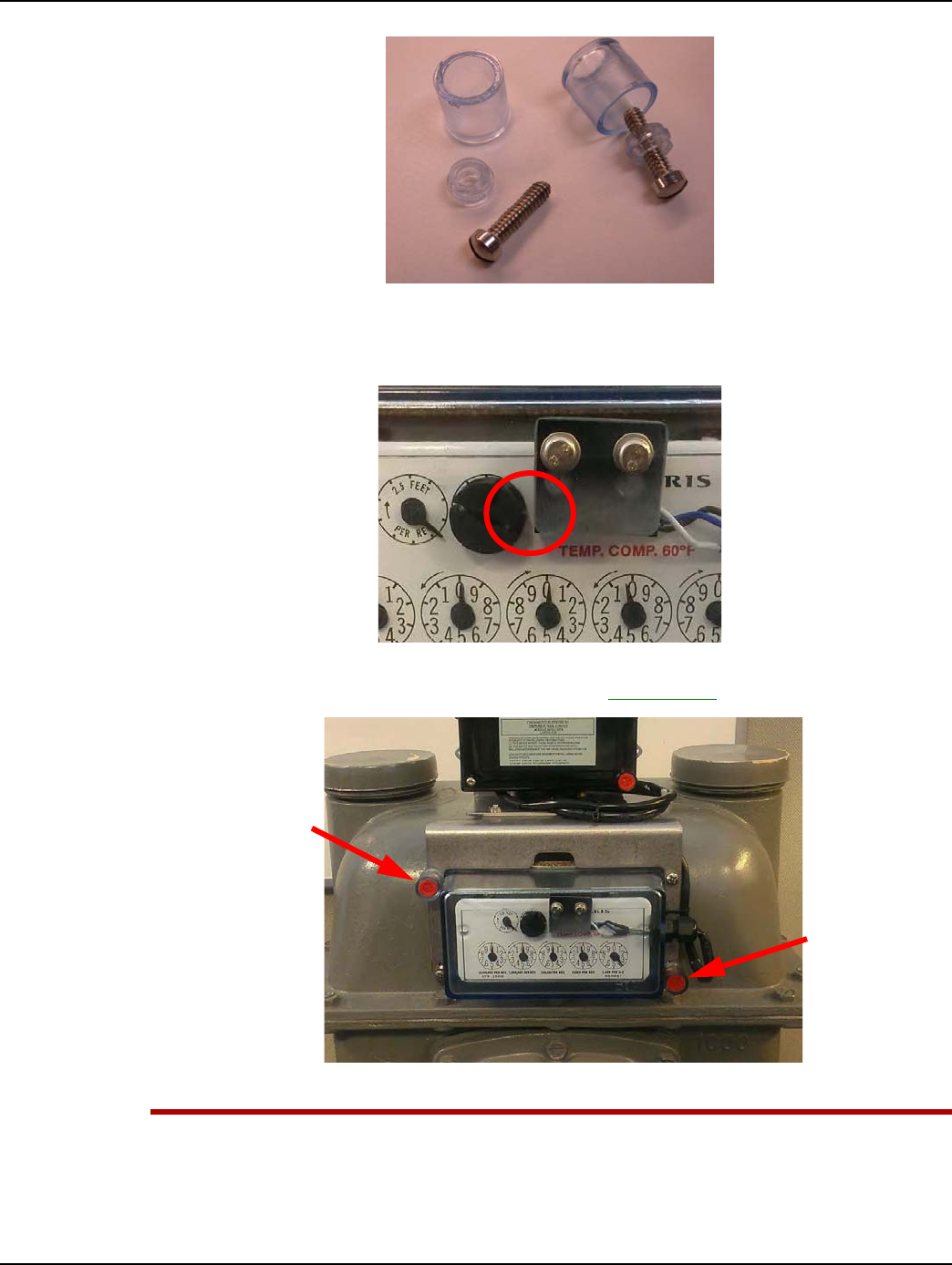
Landis+Gyr Chapter 6 - Sprague GPR Index Cover & GPR Install
Installation Guide 98-1135 Rev AB 79
Figure 6 - 23. Tamper Cups and Screws
9. Verify that the magnet wheel does not contact the switch. A visible gap must exist between the
wheel and switch as shown in the following photograph.
Figure 6 - 24. Gap Must Be Visible Between Wheel and Switch
10. Install tamper seals into the tamper cups as shown in Figure 6 - 25.
Figure 6 - 25. GPR Assembly installed on a Sprague Large Diaphragm Meter
UWARNING: Take care not to pinch the index cover switch cable assembly in any way,
especially during the following installation steps:
During index cover and cable assembly installation onto the meter.
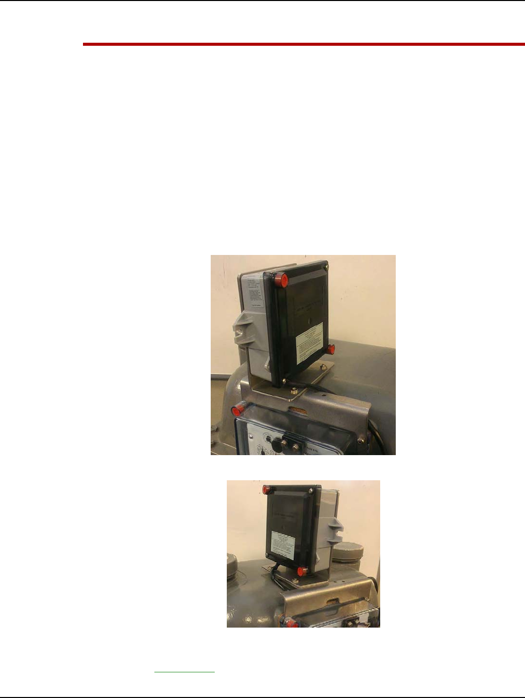
Chapter 6 - Sprague GPR Index Cover & GPR Install Landis+Gyr
80 98-1135 Rev AB Installation Guide
During GPR enclosure cover installation.
Between the GPR and meter brackets and meter.
Sprague Changing GPR Orientation
The GPR must face away from nearby walls and toward the nearest MCC or Concentrator. The GPR
may be oriented in three different directions:
•Forward toward the front of the meter
•90 degrees toward the left side of the meter
•90 degrees toward the right side of the meter
The previous instructions show the GPR facing towards the front of the meter.
The following figures show the other two possible orientations.
Choose mounting option before attaching battery and GPR cover.
Figure 6 - 26. GPR Facing Right Side of Meter
Figure 6 - 27. GPR Facing Left Side of Meter
1. Lay the GPR face down. Remove the two screws and washers holding the two brackets together
as shown in Figure 6 - 28.
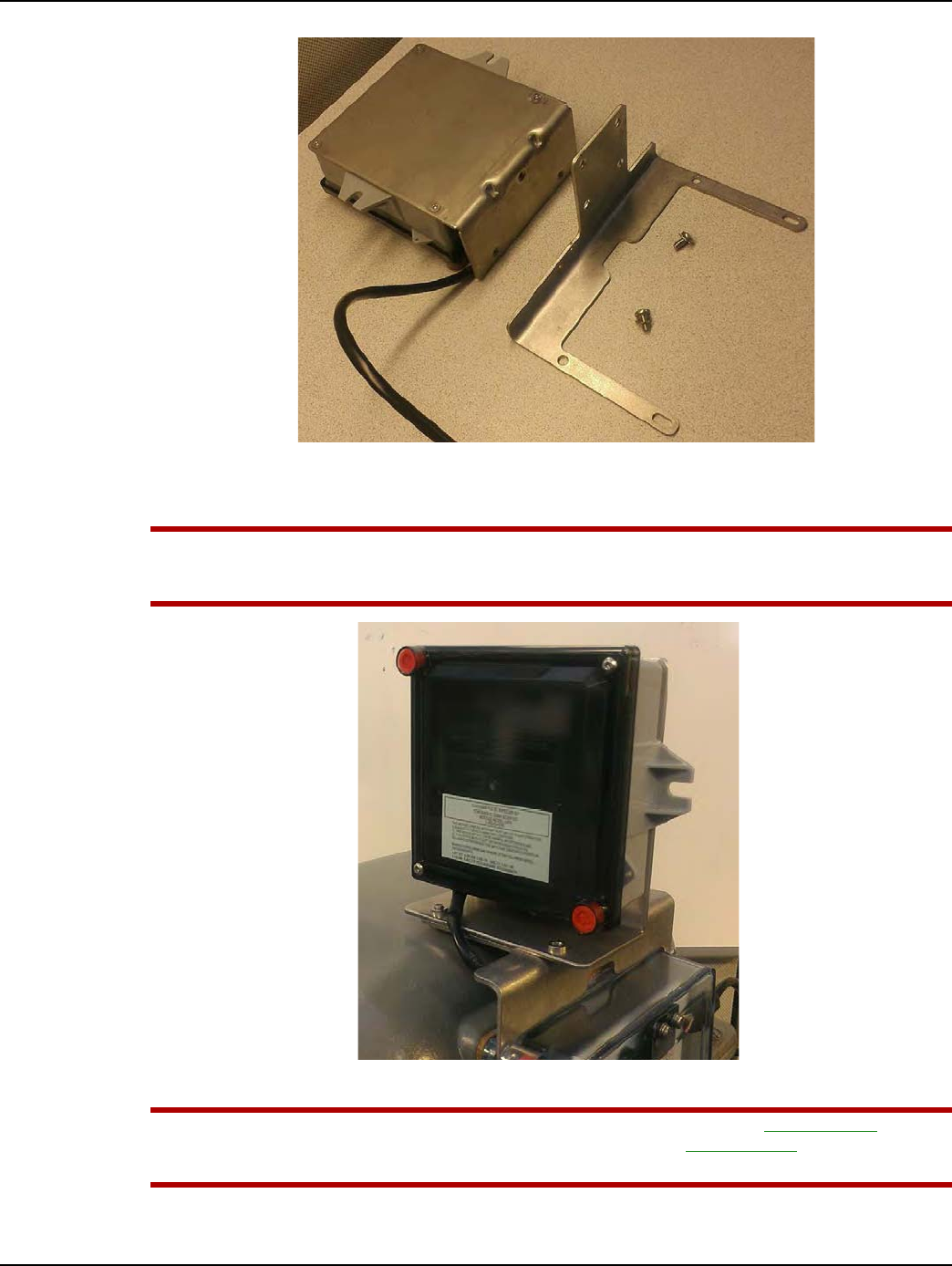
Landis+Gyr Chapter 6 - Sprague GPR Index Cover & GPR Install
Installation Guide 98-1135 Rev AB 81
Figure 6 - 28. GPR bracket disassembly
2. Determine the appropriate GPR direction.
UWARNING: The GPR must be mounted in the forward-most position on the lower bracket so
that the gas pipes do not interfere with data transmissions. Refer to the following figures for
additional detail.
Figure 6 - 29. Left-Facing GPR Shown Extended Forward to Avoid Gas Pipe Interference
UWARNING: A right-facing GPR must have the cable routed as shown in Figure 6 - 30. The
cable must not be routed around the edge of the GPR bracket (Figure 6 - 31.), where it may be
exposed to unknown hazards.
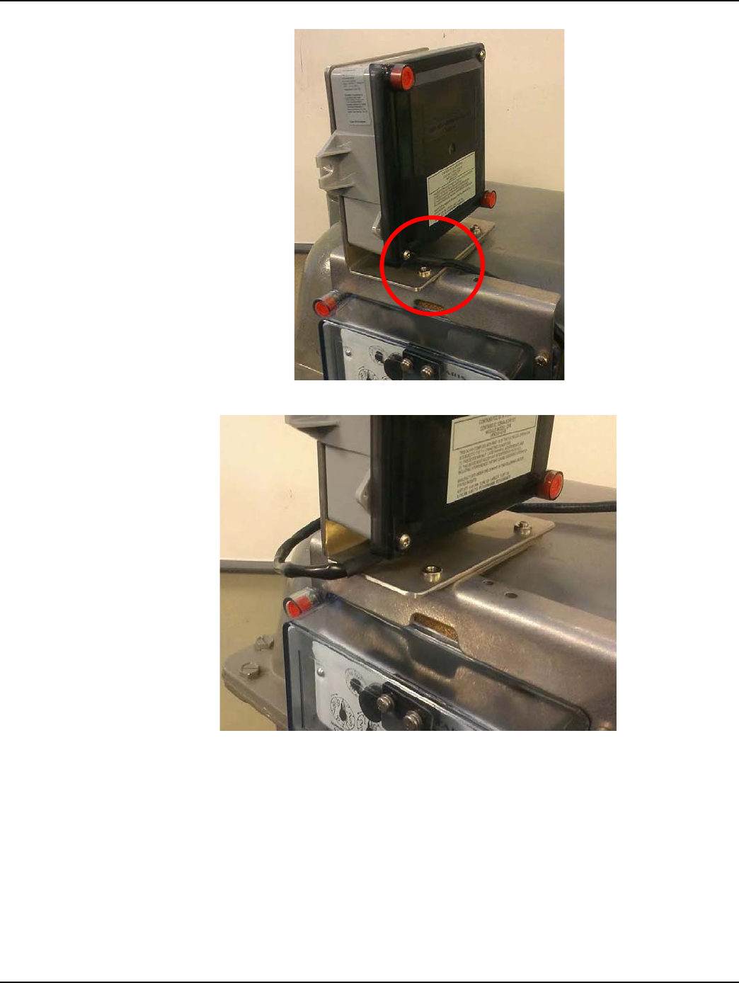
Chapter 6 - Sprague GPR Index Cover & GPR Install Landis+Gyr
82 98-1135 Rev AB Installation Guide
Figure 6 - 30. For Right-facing GPR Installs, Route Cable As Shown
Figure 6 - 31. Do Not Route the Cable In Front of the GPR Bracket - Route the Cable As Shown in
Figure D - 5
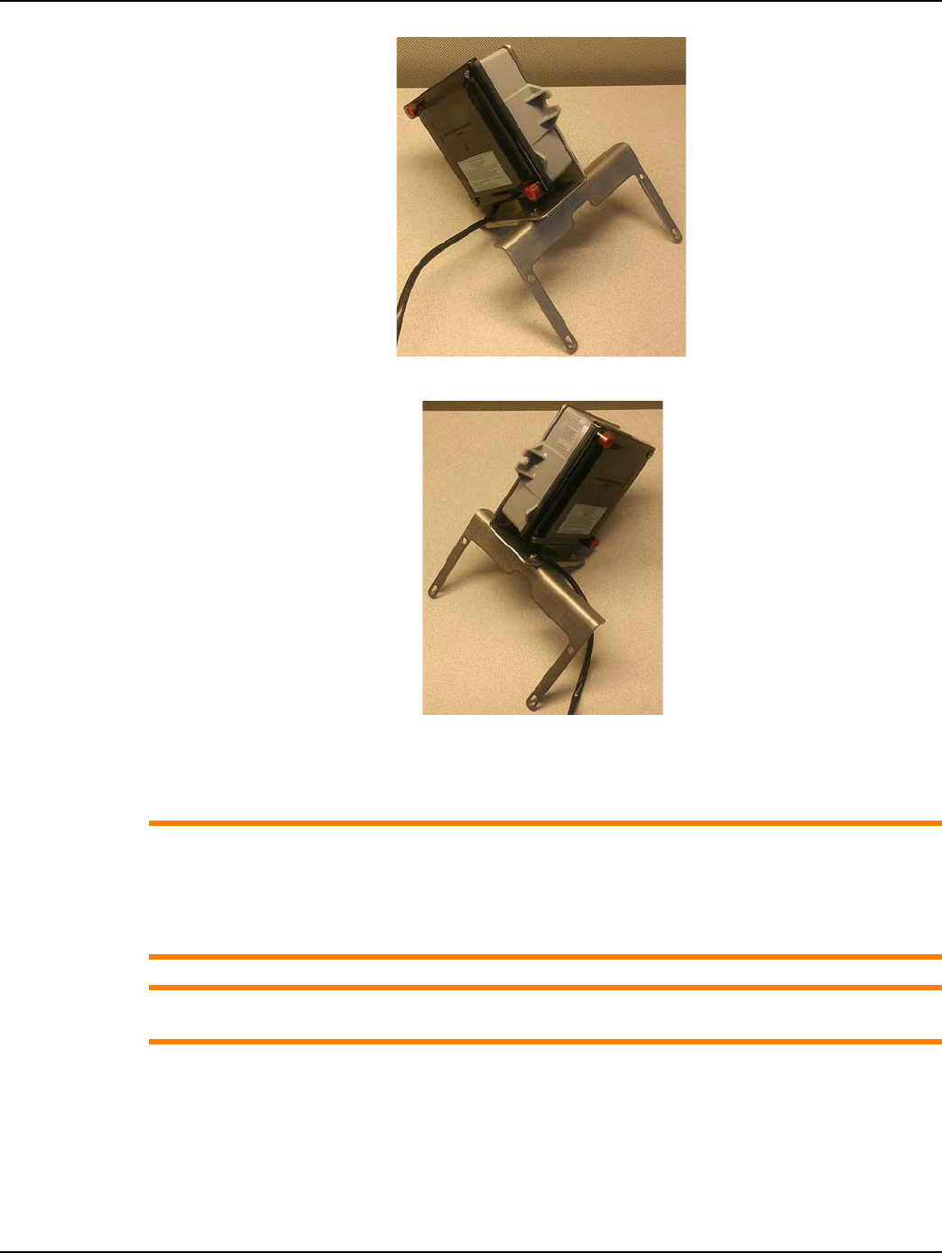
Landis+Gyr Chapter 6 - Sprague GPR Index Cover & GPR Install
Installation Guide 98-1135 Rev AB 83
Figure 6 - 32. GPR Facing Left Side of Meter
Figure 6 - 33. GPR Facing Right Side of Meter
3. Install the two screws and lock washers. Tighten the screws to 30 inch-pounds (+0 / -2 inch-
pounds).
ACAUTION: If the gas meter’s pipe route prevents installing the GPR as described in this
manual, the GPR may be mounted in a remote location away from the meter such as on a wall
or a gas pipe. The maximum cable length between the Index Cover Assembly and GPR must
not exceed 200 feet.
Remote GPR mounting is beyond the scope of this manual.
ACAUTION: In a Remote GPR Mounting environment, Pipe Bracket Kit 45-0080 may be used to
install the GPR on suitable plumbing pipes.

Chapter 6 - Sprague GPR Index Cover & GPR Install Landis+Gyr
84 98-1135 Rev AB Installation Guide
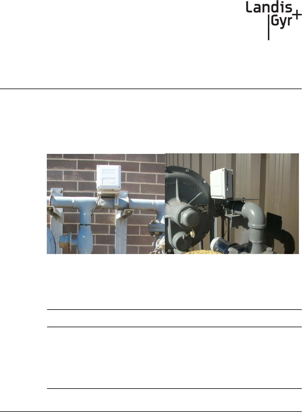
7
Installation Guide 98-1135 Rev AB 85
Electronic Pulser Installation
GPR Mounting
The GPR module will be mounted vertically and upright, on a pipe-mounting bracket in proximity to
the pulse output of the gas meter, to minimize the cable length. This bracket can accommodate pipe
diameters in the range of 2" to 3". Optionally, the GPR can be mounted on a nearby vertical surface.
The cable will be routed in order to minimize its exposure to possible damage. Figure 1 below shows
a typical installation.
Figure 7 - 1. GPR Mounting Examples
Installation Instructions for Outdoor Meters
1. Find a mounting location on a pipe near the pulse output of the meter. Attach the GPR enclosure
to the mounting bracket as shown in the following figures.
NOTE: The GPR must face away from nearby walls and should be installed in a location
unobstructed by gas pipes.
A. Determine whether the GPR is to be installed on a horizontal or vertical pipe.
•Figure 7 - 4 shows an example bracket orientation for horizontal pipe installations.
•Figure 7 - 5 shows an example bracket orientation for vertical pipe installations.
B. Attach the GPR enclosure to the L-shaped bracket through the smaller holes with four 6-20
x ½ inch security Torx screws from the GPR Pipe Mounting Kit (45-0080).
NOTE: The GPR must be installed on the bracket with the cable entry notch located at the
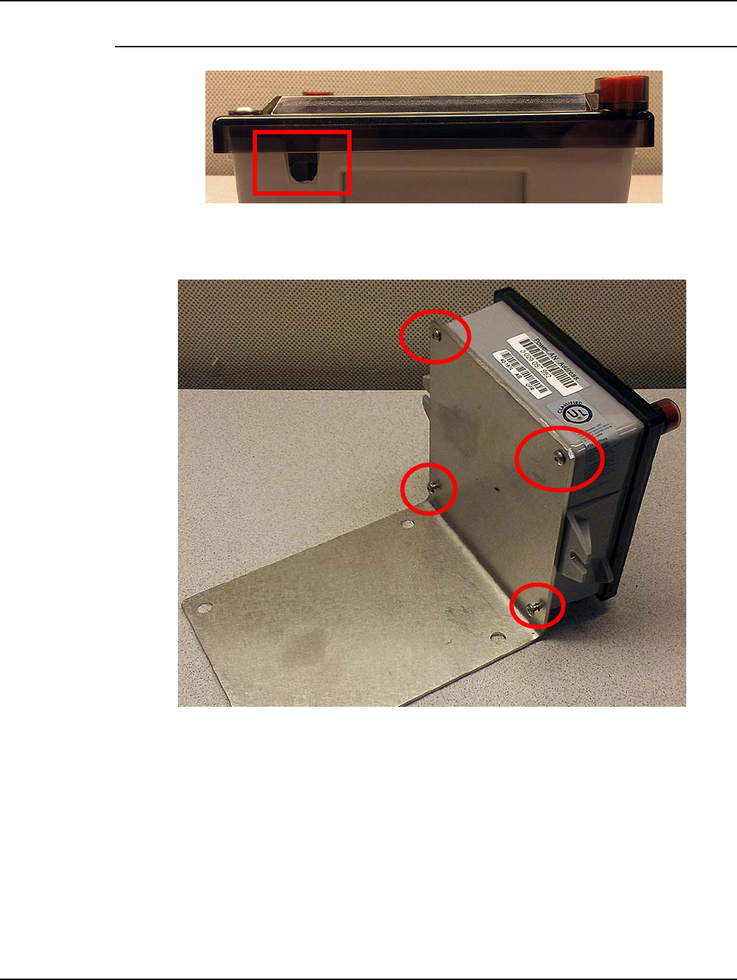
Chapter 7 - Electronic Pulser Installation Landis+Gyr
86 98-1135 Rev AB Installation Guide
BOTTOM of the enclosure to prevent dirt and moisture from collecting inside the enclosure.
Figure 7 - 2. Enclosure Cable Entry Notch
C. Using a T-10 security Torx driver, tighten the screws to 10 in-lbs (+/- 2 in-lbs). Tighten the
screws using a crisscross pattern to secure the enclosure to the bracket.
Figure 7 - 3. Attach GPR to Mounting Bracket
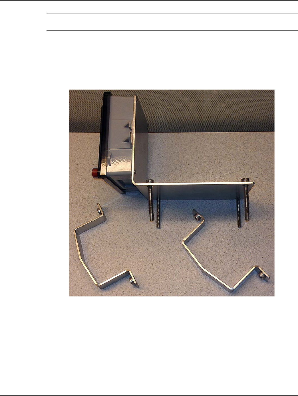
Landis+Gyr Chapter 7 - Electronic Pulser Installation
Installation Guide 98-1135 Rev AB 87
NOTE: The four longer security Torx screws are GPR enclosure cover screws. Cover screws are
included in the 40-1672 GPR kit.
2. Secure the mounting bracket with GPR to the pipe.
A. Hold the GPR bracket assembly against the pipe so that the GPR is vertical and upright.
B. Use the four 1/4-20 x 2 inch screws included with the bracket kit to install the two U-shaped
clamps around the pipe to secure the GPR bracket to the pipe.
C. Tighten the screws to 10 in-lbs (+/- 2 in-lb).
Figure 7 - 4. GPR/Bracket Assembly for Horizontal Pipe Installation
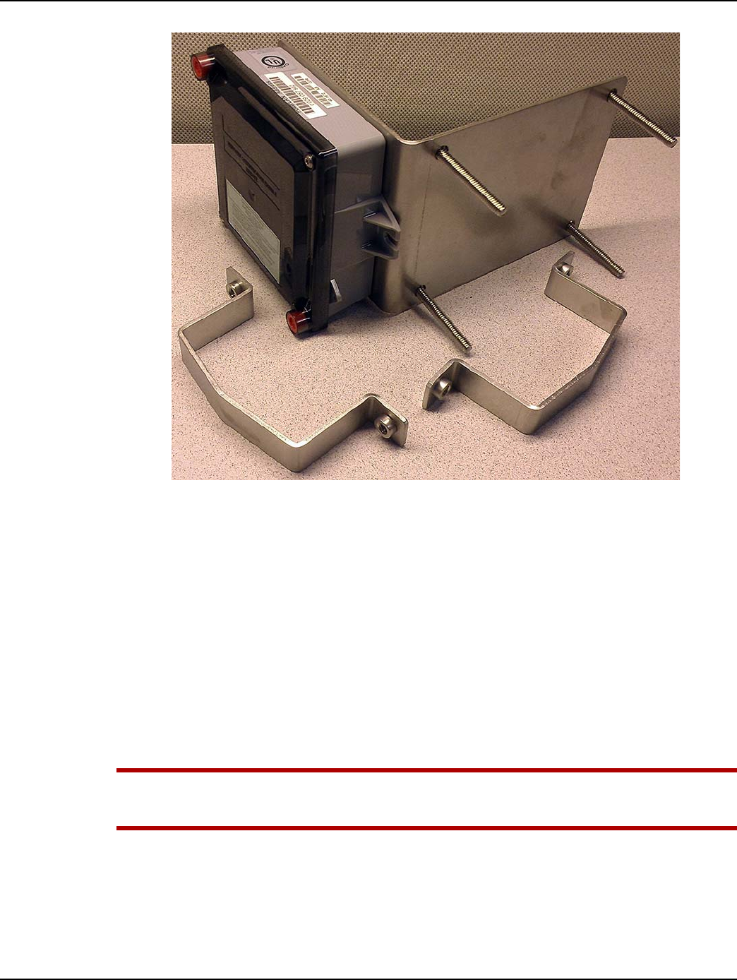
Chapter 7 - Electronic Pulser Installation Landis+Gyr
88 98-1135 Rev AB Installation Guide
Figure 7 - 5. GPR/Bracket Assembly for Vertical Pipe Installation
3. Select the appropriate cable for the meter model and pulser type onto which the GPR is to be
installed.
• Refer to the individual meter model and pulser type sections below for information on
cable selection.
4. Route the signal transmission cable along the most direct and convenient route between the
Meter and the GPR (preferably along the pipe). Secure the transmission cable to the pipe with
black nylon UV-rated tie wraps in locations along the pipe 12" apart.
5. Connect the cable to meter\pulser.
•Refer to the individual meter model and pulser type sections that follow.
•Refer to the instructions in the following sections on circular Military Style (MS) connectors
and cable splicing and crimping.
UWARNING: Refer to the meter and pulser manufacturers' instructions and warnings on
electrical wiring and electrostatic discharge. Local electrical codes must be followed when
wiring AMR devices in a gas metering environment.
Electronic Pulser Installation
Electronic pulsers include electronic rotary meters and electronic volume correctors (EVC). Typical
electronic pulsers have configurable pulse output channels. An output channel may be configured for

Landis+Gyr Chapter 7 - Electronic Pulser Installation
Installation Guide 98-1135 Rev AB 89
corrected, uncorrected, alarm, or not used. The installation information provided in this section is to
help guide the user with installing a GPR module to an electronic pulser
GPR Telemetry Specifications
•The GPR can support two volume pulse inputs and one alarm input. The pulse inputs are
organized into three channels referenced to the sensor PCB connector on the GPR circuit
board:
•By design the hardware counting channels are labeled A and B. In Command Center,
channels 1 and 2 are used.
•Channel A = Command Center channel 2
•Channel B = Command Center channel 1
•Channel A. Optional volume input.
•Channel B. Primary volume input.
•Alarm. Alarm input.
•Both channel A and B can support Form-A or Form-C type pulsers.
•The alarm channel can support Form-A or Form-B type pulsers.
•Minimum ON/OFF input pulse width is 50 mSec / 50 mSec.
•Nominal switch bias voltage is 3.0V.
•Nominal switch bias current is 30 uA.
NOTE: The billing or primary output on the pulser is to be connected to Channel B on the GPR.
NOTE: It is the responsibility of the user to make sure the output pulse meets the minimum pulse
ON/OFF time. This is usually a configurable parameter for electronic volume correctors.
NOTE: When both channels, A and B, are connected and used as volume inputs in an installation, it
is highly recommended that both channels are connected and configured for type Form-A at the
pulser side as well as the GPR side. If Form-C is used in a dual volume input configuration, the
battery life of the GPR is not guaranteed.
NOTE: The GPR should not be connected to any output that has power. It is a good practice to
measure the output of the pulser before installing to the GPR. Voltage above 6.0V can cause
damage to the GPR and will violate the intrinsic safety rating.
NOTE: If the battery is unplugged, do not connect the battery until the module is ready for operation
to start.
Table 7 - 1. Definitions
Term Definition
NO Normally Open
NC Normally Closed
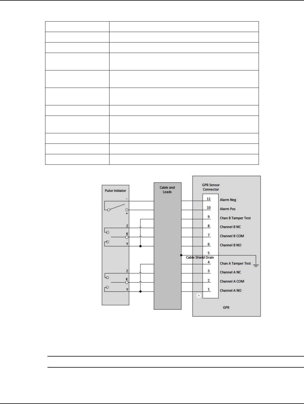
Chapter 7 - Electronic Pulser Installation Landis+Gyr
90 98-1135 Rev AB Installation Guide
Figure 7 - 6. Sensor Channels
The figure below shows location of the Pin #1 on the GPR sensor connector and where the battery
connection is.
NOTE: Battery should not be connected until GPR is fully mounted.
COM Common
N/C No Connection
Pulser The pulse generating device on the meter, such as an
electronic volume corrector or electronic rotary meter
Form-A SPST, normally open switch, requires the COM and NO
terminals
Form-B SPST, normally closed switch, requires the COM and NC
terminals
Form-C SPDT switch, requires the COM, NO, and NC terminals
GPR Sensor Connector This is the connector on the GPR's circuit board, not the one
on the cable
K Common terminal, COM
Y Normally open terminal, NO
Z Normally closed terminal, NC
Table 7 - 1. Definitions
Te r m D e f i n i t i o n
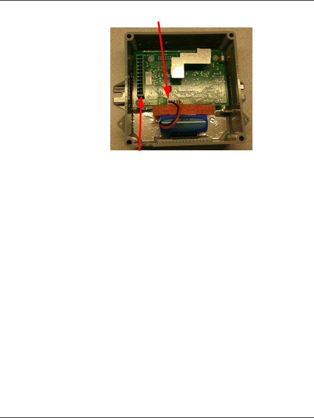
Landis+Gyr Chapter 7 - Electronic Pulser Installation
Installation Guide 98-1135 Rev AB 91
Figure 7 - 7. GPR Module Interior
Interface to a Single Form-A Volume Output
For a single Form-A volume pulse output, connect the pulser to Chan B of the GPR using the
recommended cable 19-2330. The installation procedure is as follows.
1. Refer to the user manual of the pulser for information on its pulse outputs interface. The pulse
output interface on the pulser may be a terminal block or flying leads. A terminal on the terminal
block is usually labeled K, Y, or Z.
2. Connect the DRAIN lead to the drain terminal on the pulser output connector. The drain
connection is optional.
3. Connect both the CHAN B NO and CHAN B TAMPER TEST leads to the Y terminal on the
pulser output connector.
4. Connect the CHAN B COM lead to the K terminal on the pulser output connector.
5. Apply Di-Electric Grease Compound to the sensor connector.
6. Connect the cable connector to the GPR sensor connector. Make sure the cable connector is
correctly mated to the pins on the GPR sensor connector, otherwise the GPR will not detect
pulses. See the figures and table below. Make sure pin #5 on the cable connector is mated to pin
#5 on the sensor connector.
Battery Connection
GPR Sensor Connector Pin #1
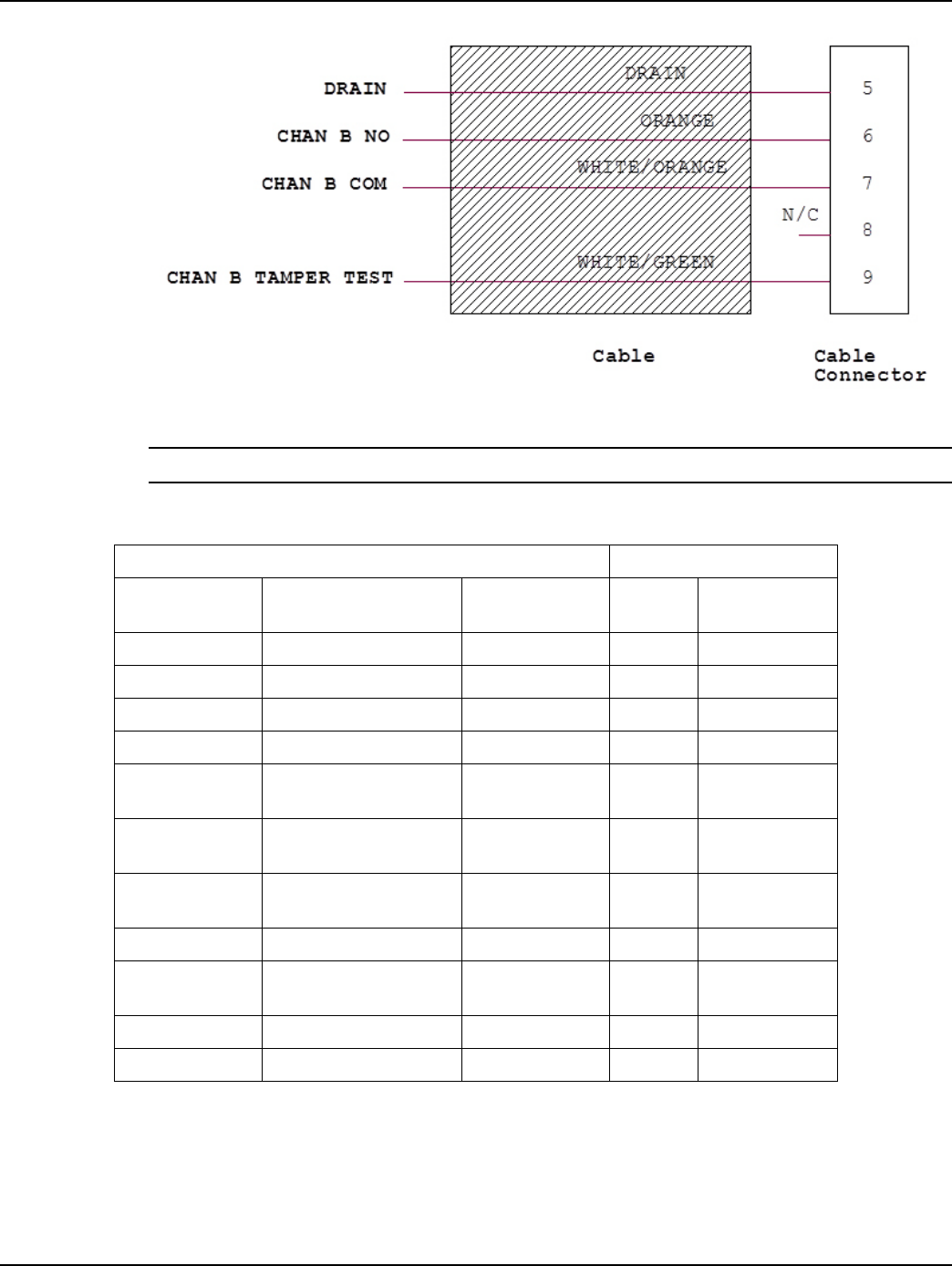
Chapter 7 - Electronic Pulser Installation Landis+Gyr
92 98-1135 Rev AB Installation Guide
Figure 7 - 8. Wiring for a Single Form-A Volume Input
NOTE: The cable connector is shown downside up.
Table 7 - 2. Single Form-A Volume Input Definitions
GPR 19-2330 Cable Pulser Output Connector
GPR Sensor
Connector Pin # Signal and Description Lead Color Terminal Description
and Notes
1 N/C N/A N/A Not Applicable
2 N/C N/A N/A Not Applicable
3 N/C N/A N/A Not Applicable
4 N/C N/A N/A Not Applicable
5Ground Drain Drain
Connection is
optional
6CHAN B NO, Channel B
normally open Orange Y Normally Open
7CHAN B COM, Channel
B common WHITE/ORANGE K Common
8 N/C N/A N/A Not Applicable
9CHAN B TAMPER TEST,
channel B tamper test WHITE/GREEN Y Tamper test
10 N/C N/A N/A Not Applicable
11 N/C N/A N/A Not Applicable
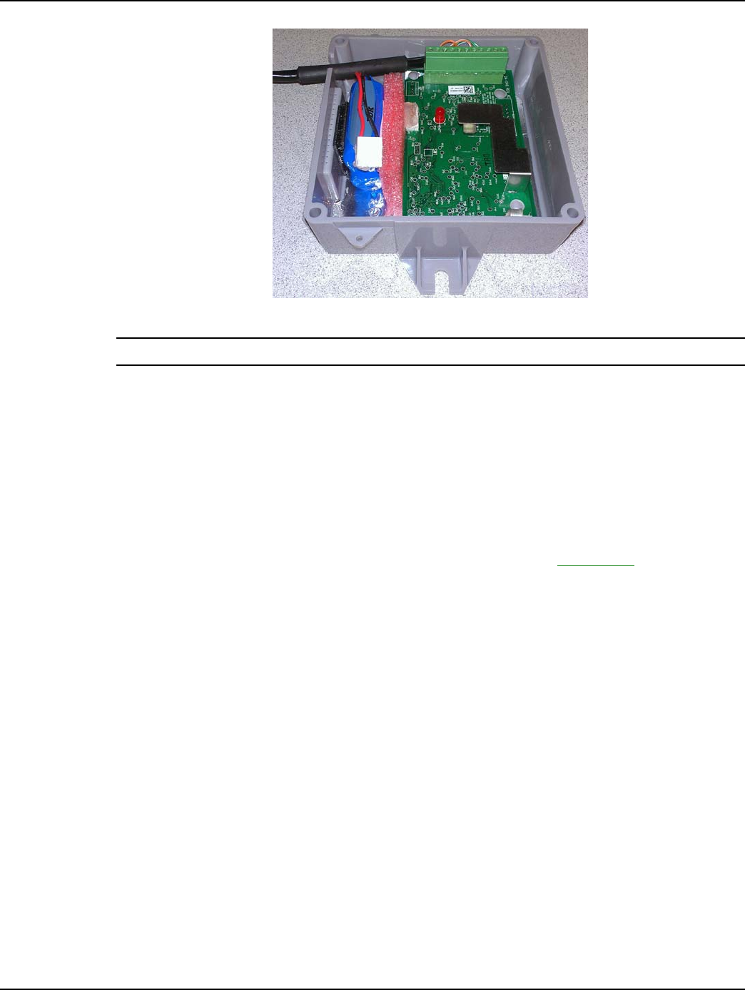
Landis+Gyr Chapter 7 - Electronic Pulser Installation
Installation Guide 98-1135 Rev AB 93
Figure 7 - 9. Cable to GPR Connection for a Single Form-A Volume Input
NOTE: Battery should not be connected until GPR is fully mounted.
Interface to Mil-Spec Circular Connector
For pulsers that have one or two Form-A outputs through a Mil-Spec circular connector, the
recommended cable for use is 19-2332. The installation procedure is as follows.
1. Refer to the pulse outputs section of the pulser's installation manual and check to make sure the
signal interface corresponds to the definitions shown in the table below.
2. Connect the male circular connector on the cable to the pulse output connector on the pulser.
3. Apply Di-Electric Grease Compound to the sensor connector. See Appendix A, GPR
Waterproofing for more information.
4. Connect the cable connector to the GPR sensor connector.
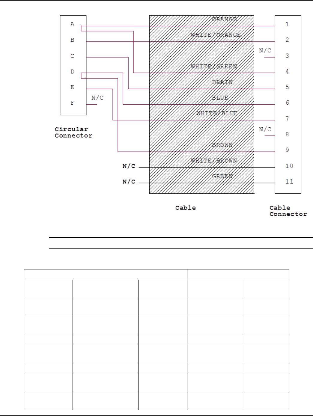
Chapter 7 - Electronic Pulser Installation Landis+Gyr
94 98-1135 Rev AB Installation Guide
Figure 7 - 10. Circular Connector Wiring for Two Form-A Volume Inputs
NOTE: The cable connector is shown downside up.
Table 7 - 3. Two Form-A Volume Inputs Wiring Definitions
GPR 19-2332 Cable Pulser Output Connector
GPR Sensor
Connector Pin # Signal and Description Lead Color Circular Connector
Pin Label Description
1CHAN A NO, channel A
normally open ORANGE A Normally Open
2CHAN A COM, Channel
A common WHITE/ORANGE B Common
3 N/C N/A N/A Not Applicable
4CHAN A TAMPER TEST,
Channel A tamper test WHITE/GREEN A Normally Open
5 Ground Drain C Drain
6CHAN B NO, Channel B
normally open BLUE D Normally Open
7CHAN B COM, Channel
B common WHITE/BLUE E Common

Landis+Gyr Chapter 7 - Electronic Pulser Installation
Installation Guide 98-1135 Rev AB 95
Interface to Multi-Outputs
The cable 19-2331 can be used for multi-output interfaces such as conduit, cable gland, or terminal
block. This cable supports only Form-A volume outputs.
The general installation procedure is as follows.
1. Refer to the pulse outputs section of the pulser's installation manual.
2. Connect the DRAIN lead to the drain terminal on the pulser output connector. The drain
connection is optional.
3. Make connection to the volume pulse output channels and alarm channel according to the table
below.
4. Apply Di-Electric Grease Compound to the sensor connector. See Appendix A, GPR
Waterproofing for more information.
5. Connect the cable connector to the GPR sensor connector.
8 N/C N/A N/A Not Applicable
9CHAN B TAMPER TEST,
channel B tamper test GREEN D Normally Open
10 N/C N/A N/A Not Applicable
11 N/C N/A N/A Not Applicable
Table 7 - 3. Two Form-A Volume Inputs Wiring Definitions
GPR 19-2332 Cable Pulser Output Connector
GPR Sensor
Connector Pin # Signal and Description Lead Color Circular Connector
Pin Label Description
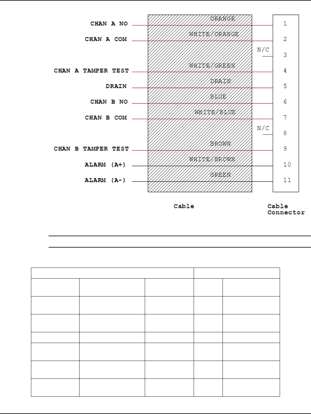
Chapter 7 - Electronic Pulser Installation Landis+Gyr
96 98-1135 Rev AB Installation Guide
Figure 7 - 11. Flying Leads Wiring for Two Form-A Volume Inputs and Alarm
NOTE: The cable connector is shown downside up.
Table 7 - 4. Two Form-A and Alarm Wiring Definitions
GPR 19-2331 Cable Pulser Output Connector
GPR Sensor
Connector Pin # Signal and Description Lead Color Terminal Description
1CHAN A NO, channel A
normally open ORANGE Y1 Normally Open
2CHAN A COM, Channel
A common WHITE/ORANGE K1 Common
3 N/C N/A N/A Not Applicable
4CHAN A TAMPER TEST,
Channel A tamper test WHITE/GREEN Y1 Tamper Test
5Ground DrainDrain
Connection is
Optional
6CHAN B NO, Channel B
normally open BLUE Y2 Normally Open

Landis+Gyr Chapter 7 - Electronic Pulser Installation
Installation Guide 98-1135 Rev AB 97
Start the GPR Operation In Install Mode
By now, the GPR should be fully mounted without it's cover.
The GPR module, as received from the contract manufacturer, should have the correct Network
LAN ID and CRC numbers already configured. The GPR, when installed for the first time, will start
operation in Install Mode. Install Mode is a temporary operation mode during which the GPR
initiates the first network synchronization, and performs auto-registration to Command Center. To be
able to sync to a network the GPR must have the same CRC number as that of the Network. During
auto-registration the GPR requests for operation and meter specific configurations from Command
Center. When the new configuration data is obtained, the GPR reconfigures itself, reboots, and then
changes operation to Normal Mode.
Once the GPR is properly mounted and connected to the pulser, it is ready for operation to start. To
start the GPR in Install Mode follow the procedure below.
1. The sensor cable should be installed before the battery connection to avoid false counts at
startup.
2. Apply dielectric grease compound to the battery connector. See Appendix A, GPR
Waterproofing for more information.
3. Apply power to the module by making the battery connection.
4. Remove the foam between the battery and the PCB and discard it.
5. Observe the LED on the module for proper start up. Shortly after power is applied the LED will
flash once every 5 seconds for 60 seconds to indicate to the installer that the module is in
Installation Mode, and is operating normally. If an error is encountered, the LED will flash twice
per second to indicate there is an error and continue flashing until power is disconnected.
6. If the module started operation correctly, mount the cover as shown in the next 3 steps.
7. Arrange the GPR Pulse Input and Battery Interface cables as shown in Figure 7 - 12. The cables
must not interfere with or block the GPR antenna.
7CHAN B COM, Channel
B common WHITE/BLUE K2 Common
8 N/C N/A N/A Not Applicable
9CHAN B TAMPER TEST,
channel B tamper test Brown Y2 Tamper Test
10 ALARM (A+), positive
alarm WHITE/BROWN A+ No Connection
11 ALARM (A-), negative
alarm GREEN A- No Connection
Table 7 - 4. Two Form-A and Alarm Wiring Definitions
GPR 19-2331 Cable Pulser Output Connector
GPR Sensor
Connector Pin # Signal and Description Lead Color Terminal Description
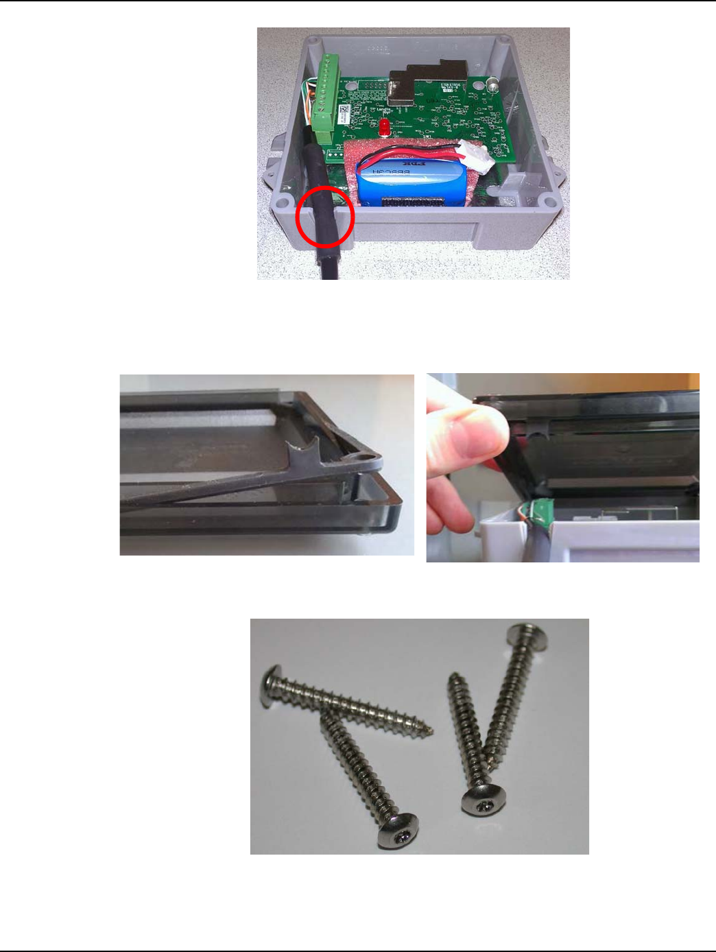
Chapter 7 - Electronic Pulser Installation Landis+Gyr
98 98-1135 Rev AB Installation Guide
Figure 7 - 12. Pulse Interface Cable's Shrink Tubing Must Route Through GPR Strain Relief Slot
8. Install the GPR cover using the four security Torx screws included with the GPR. The cover
must be installed with the gasket tab inserted into the strain relief slot located at the bottom left
corner of the GPR enclosure as shown in the following photos.
Figure 7 - 13. GPR Cover Gasket Tab and Cover Strain Relief Slot
9. Tighten the screws to 13 inch-pounds (± 1 inch-pound).
Figure 7 - 14. GPR Cover Screws
10. Install tamper seals into the tamper cups that are part of the GPR cover.
11. Installation is now complete.
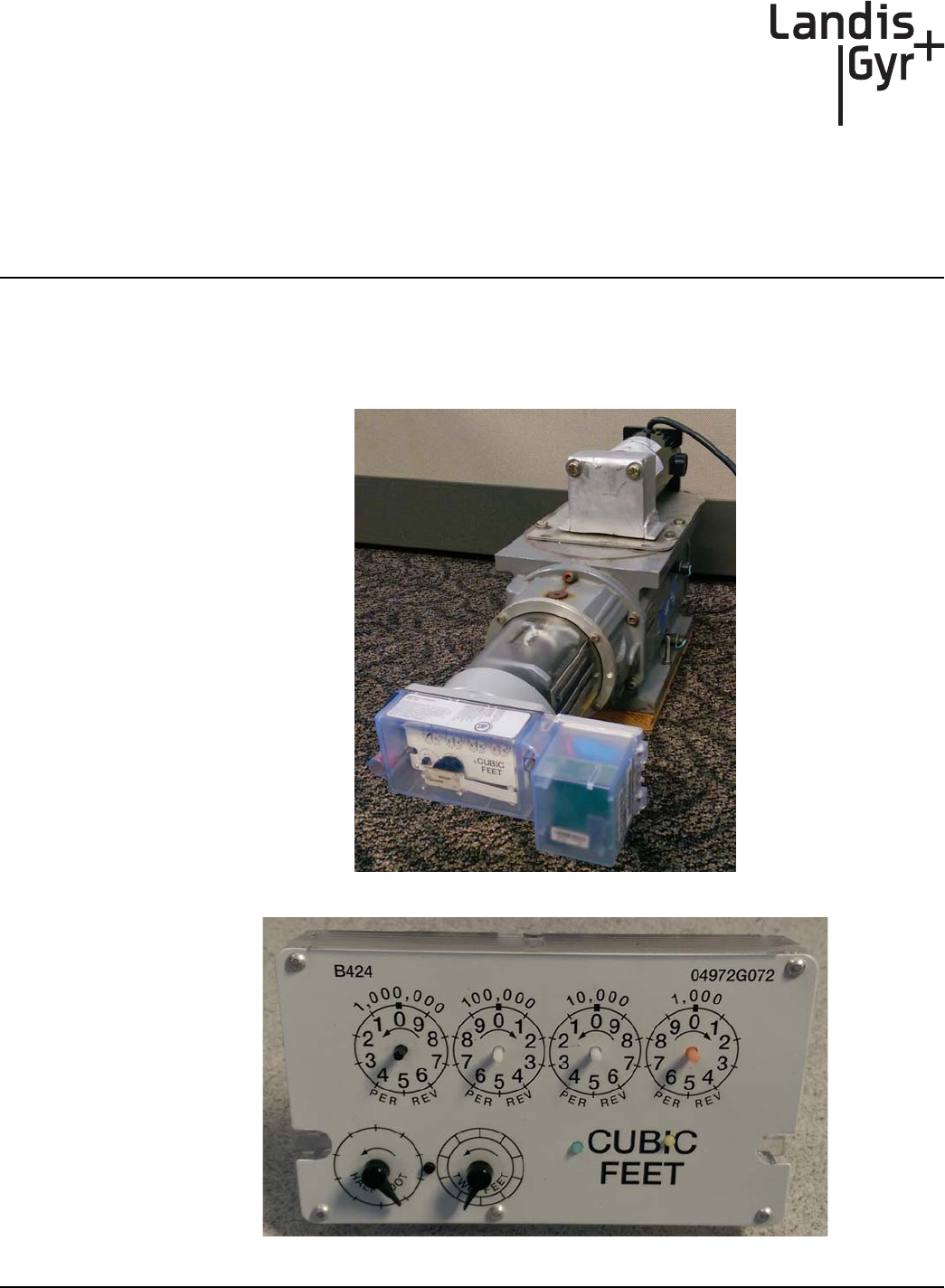
8
Installation Guide 98-1135 Rev AB 99
Dresser Roots Installation
Meter Module Retrofit
Prior to adding the M120-1 module, follow instructions provided in the GE AMR kit (45-2476) to
add the AMR adapter. This adapter is needed for attaching the proper index.
Figure 8 - 1. Dresser Roots Meter w/ M120 2-way Module
Figure 8 - 2. 01-1337 Index should only have the 2 lower pointers
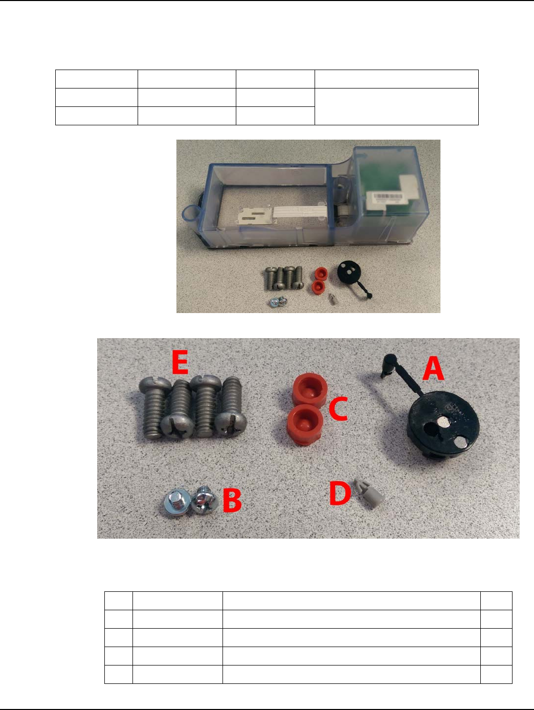
Chapter 8 - Dresser Roots Installation Landis+Gyr
100 98-1135 Rev AB Installation Guide
Validated Meter Index Part Numbers
Figure 8 - 3. M120-1 Meter Module Kit Before Installation
Figure 8 - 4. M120-1 Dial Wheel and Seals Hardware Kits #45-1219
Table 8 - 1. 01-1337 Index Parameters
Index Type American Part No. Dial or “B” No. Use Gridstream M120-1 Model No.
2 Ft. Pointer 04972G072 B424
26-1307
2 Ft. Pointer 04972G087 B683
Table 8 - 2. M120-1 Dial Wheel and Seals Hardware Kit #45-1219
Item Number Item Name Qty.
A 40-0417 Sub-Assy, GasLX, Dial Wheel 1
B 22-1176 Screw, 8-32 x 3/16", PNH, PHH & SLH, STL, ZN 2
C 22-0278 Seal, Tamper, C&I Gas, Sprague 2
D 29-1322 Dial Wheel, Pin, American, New Index Pointer 1
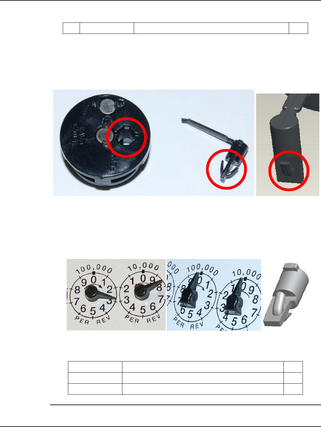
Landis+Gyr Chapter 8 - Dresser Roots Installation
Installation Guide 98-1135 Rev AB 101
Dial Wheel Installation
After the battery is installed, prepare to install the Dial Wheel onto the index. This step can be
accomplished with the index on the meter, or on a meter index that is not installed on a meter.
Figure 8 - 5. Dial Wheel Kit (note Dial Wheel Pin Tab Hole indentations); Black Dial Wheel Pin
Some American indexes have square-edge index pointers that require updated dial wheel pins.
Special dial wheel pins are molded with gray-colored material for differentiation. Examples of the
round-edge and square-edge index pointers and the modified pin for use with the square-edge
pointers appear below. The gray pin should only be used with square-edge index pointers. The black
pin can only be used with round-edge index pointers.
Figure 8 - 6. Round-edge vs. Square-edge American Index Pointers; Gray Dial Wheel Pin
NOTE: Kit 45-2400 includes two thread rolling screws. These should be used in place of the two
machine screws (22-1176) only to mount the index of 01-1337 and if there is no metal insert within
E 22-1177 Screw, 1/4-20 x 5/8", FILH, PHH & SLH, STL 4
Table 8 - 2. M120-1 Dial Wheel and Seals Hardware Kit #45-1219
Table 8 - 3. American Index, Pointers Removed, GE AMR (Kit #45-2400)
Item Number Item Name Qty.
01-1337 Index, Dial, American Res Gas, Pointers Removed 1
22-1426 Screw, M4-.7 x 8mm, Pan Philips, Thread Rolling, Steel, Zinc 2
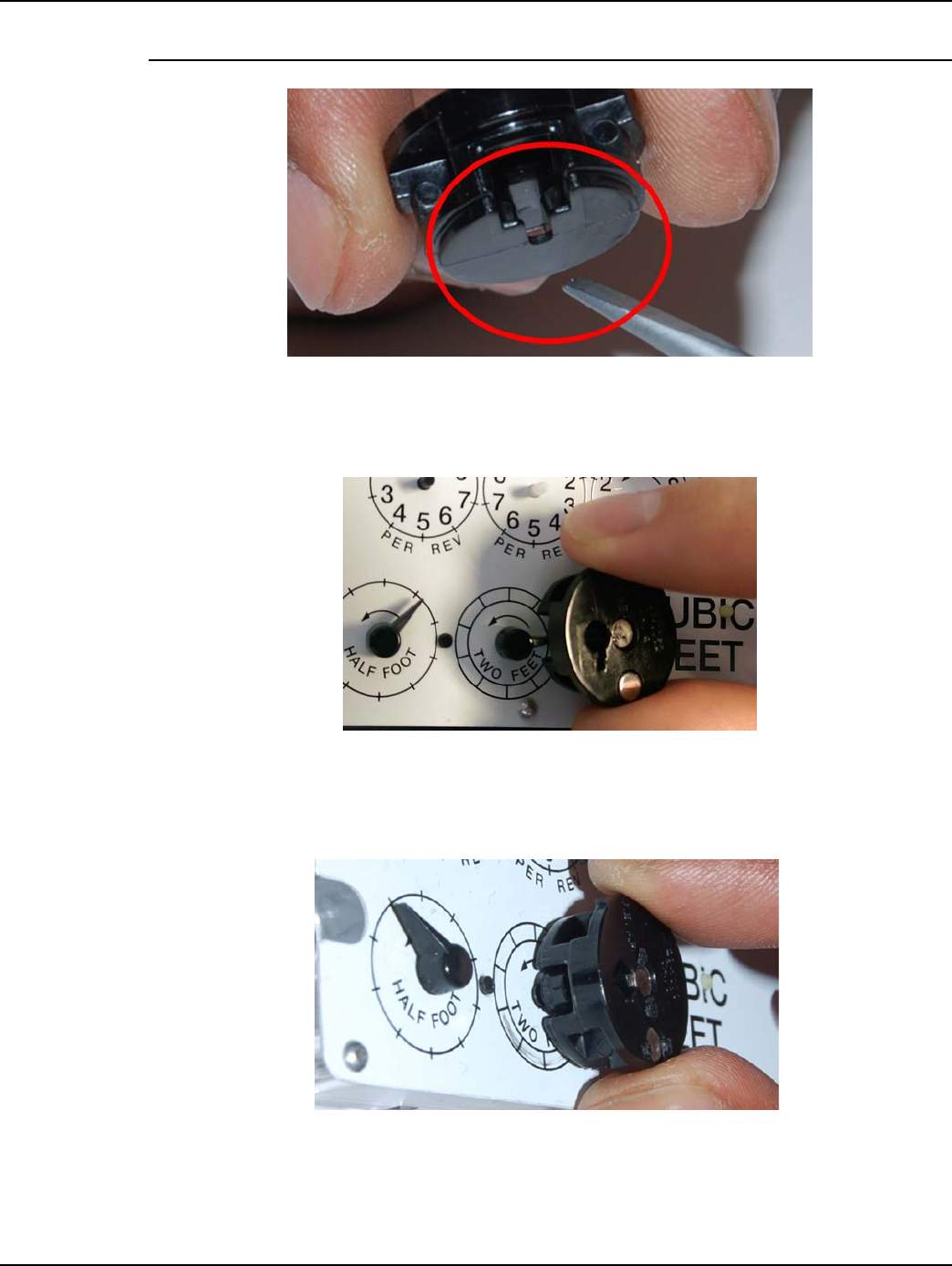
Chapter 8 - Dresser Roots Installation Landis+Gyr
102 98-1135 Rev AB Installation Guide
the index screw hole bosses.
Figure 8 - 7. Dial Wheel Pointer Slot
1. While holding the Dial Wheel, note the location of the Pointer Slot. With the index sitting on a
work surface, set the Dial Wheel on the index face with the pointer slot oriented towards the
pointer.
Figure 8 - 8. Dial Wheel with pointer slot positioned for pointer entrance
2. Slide the Dial Wheel toward the pointer on the test hand until the Dial Wheel center contacts the
pointer. The pointer center will gently impede the Dial Wheel. Do not force the Dial Wheel onto
the pointer center.
Figure 8 - 9. Dial Wheel placed on pointer
3. Take the Dial Wheel Pin and insert the pin into the Dial Wheel hole. Note the position of the
three tabs of the Dial Wheel pin. Use the plastic connecting strip to orient the Dial Wheel pin to
fit into the corresponding slot of the Dial Wheel Pin hole.
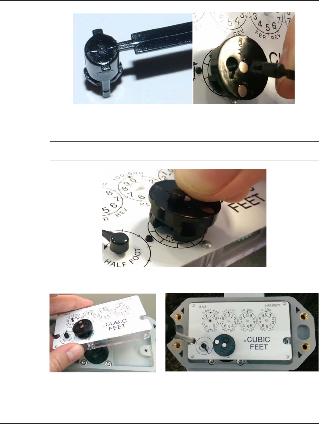
Landis+Gyr Chapter 8 - Dresser Roots Installation
Installation Guide 98-1135 Rev AB 103
Figure 8 - 10. Orienting the Dial Wheel Pin before installation
4. You will feel a gentle click as the pin seats into place. Snap off or cut away the plastic
connecting strip.
NOTE: When the index employs square-edge pointers and the gray pin is used, there will be no
connecting strip to cut away.
Figure 8 - 11. Installing the Dial Wheel Pin
Install the index onto the AMR adapter. Tighten screws (22-1176) to 15 +/- 2 inch-pounds.
Figure 8 - 12. Attaching the Index
If there are no metal inserts within the screw hole bosses for the index, use the thread rolling
screws (22-1426) instead of the machine screws (22-1176). Tighten to 5 +/- 0.5 inch-pounds.
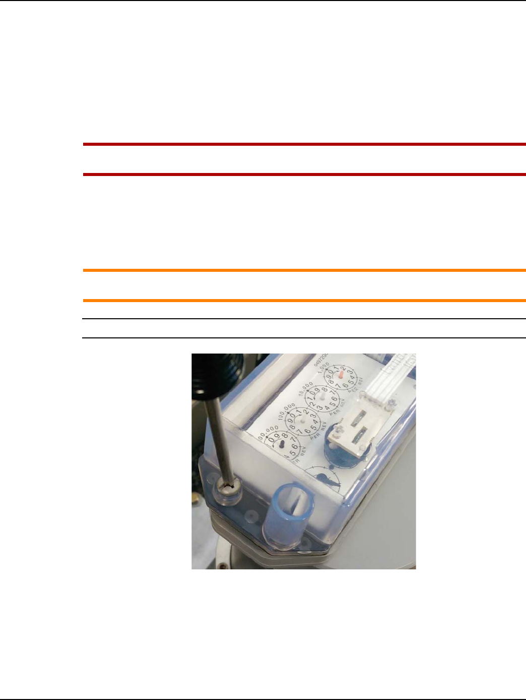
Chapter 8 - Dresser Roots Installation Landis+Gyr
104 98-1135 Rev AB Installation Guide
Dial Wheel Installation Cautions
When mounted dial wheels are not properly centered on index dial pointers, generally due to
incorrect clip seating, negative results may include:
1. index damage
2. drag during operation
3. data read inconsistency
UWARNING: Dial wheel mounting is a critical installation parameter that must be done
correctly to avoid negatively impacting read data actions.
Installing the Module
1. Using the four original mounting screws, prepare to install the meter module onto the meter.
Install, but do not tighten to mounting torque, the first of the module mounting screws.
ACAUTION: Discard the foam spacer in the Gridstream M120-1 index cover compartment
before mounting the index cover onto the meter.
NOTE: Use a torque screwdriver to tighten the screws to 15 +/- 2 inch-pounds.
Figure 8 - 13. Installing a Gridstream M120-1 Meter Module Cover Mounting Screw
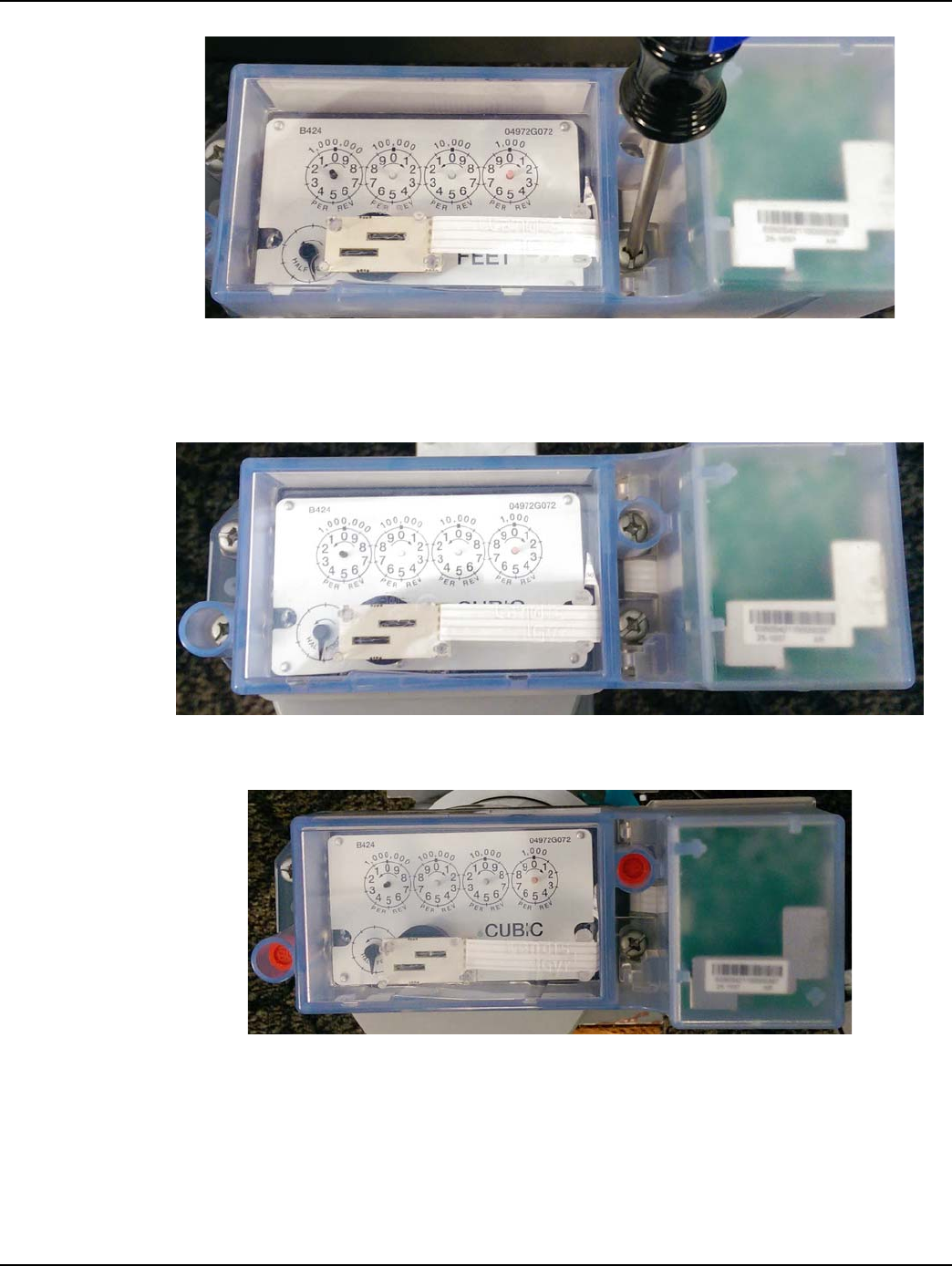
Landis+Gyr Chapter 8 - Dresser Roots Installation
Installation Guide 98-1135 Rev AB 105
Figure 8 - 14. A Screw-holding Screwdriver Will Simplify Installing This Mounting Screw
2. Install the remaining screws. If available, using a screw-holding screwdriver to install the lower
right-side module mounting screw will simplify this action. Tighten the screws to a torque rating
of 15 +/- 2 inch-pounds.
Figure 8 - 15. Index and Gridstream M120-1 Index Cover Installed
3. Install new tamper seals over the upper right and lower left mounting screws.
Figure 8 - 16. Meter module with security seals installed
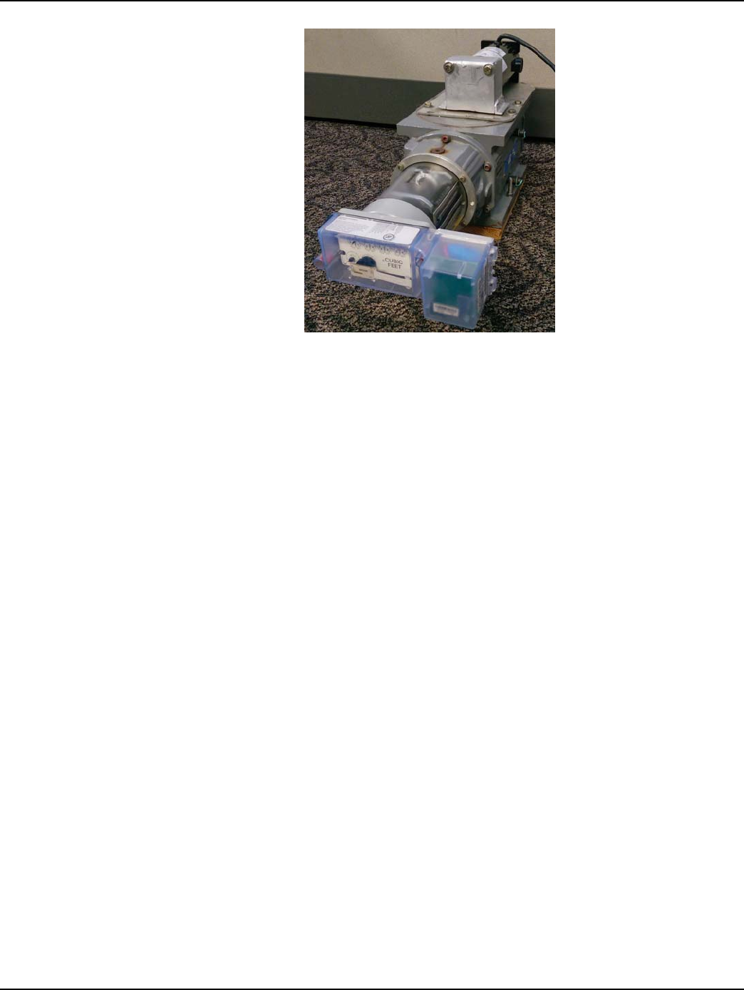
Chapter 8 - Dresser Roots Installation Landis+Gyr
106 98-1135 Rev AB Installation Guide
Figure 8 - 17. Dresser Roots meter after installation
4. Clean up debris from the retrofit and installation processes. If required by local practice, enter
the appropriate information on a door hanger tag.
5. At the end of the day, the installer returns to the Cross Dock for the check-in process. The
installer should also turn in inventory of unused, defective, or broken gas Meter Modules. The
installer is responsible for reconciling any discrepancies in changed data before the check-in
process can be completed.
Operation Startup
The M120 module, as received from the contract manufacturer, should have the correct Network
LAN ID and CRC numbers already configured. The operating mode of the module, as received from
the contract manufacturer, should be Deep Sleep or standby mode. Once the M120 is properly
mounted and connected to the meter, it is ready for operation to start in Install Mode. Install Mode is
a temporary operation mode during which the M120 initiates the first network synchronization, and
performs auto-registration to Command Center. To be able to sync to a network the M120 must have
the same CRC number as that of the Network. During auto-registration the M120 requests for
operation and meter specific configurations from Command Center. When the new configuration
data is obtained, the M120 reconfigures itself, reboots, and then changes operation to Normal Mode.
To start a fresh M120 in Install Mode use one of the following methods.
1. If the gas meter is active, meaning gas is flowing, the module will automatically switch to Install
Mode after a preset wakeup_rotations number of dial wheel revolutions. The wakeup_rotations
value is currently 25, and is subject to change. After the number of rotations is met, verify that
the LED on the module is flashing every 5 seconds to indicate that it is in Install Mode.
2. If the gas meter is inactive, meaning there is no gas flow, place a magnet by the module as shown
in the picture below. Hold the magnet until the LED lights up. This can take more than 10
seconds. When the LED lights up, hold the magnet for 10 more seconds and then remove. Verify
that the LED is now flashing every 5 seconds to indicate that it is in Install Mode.
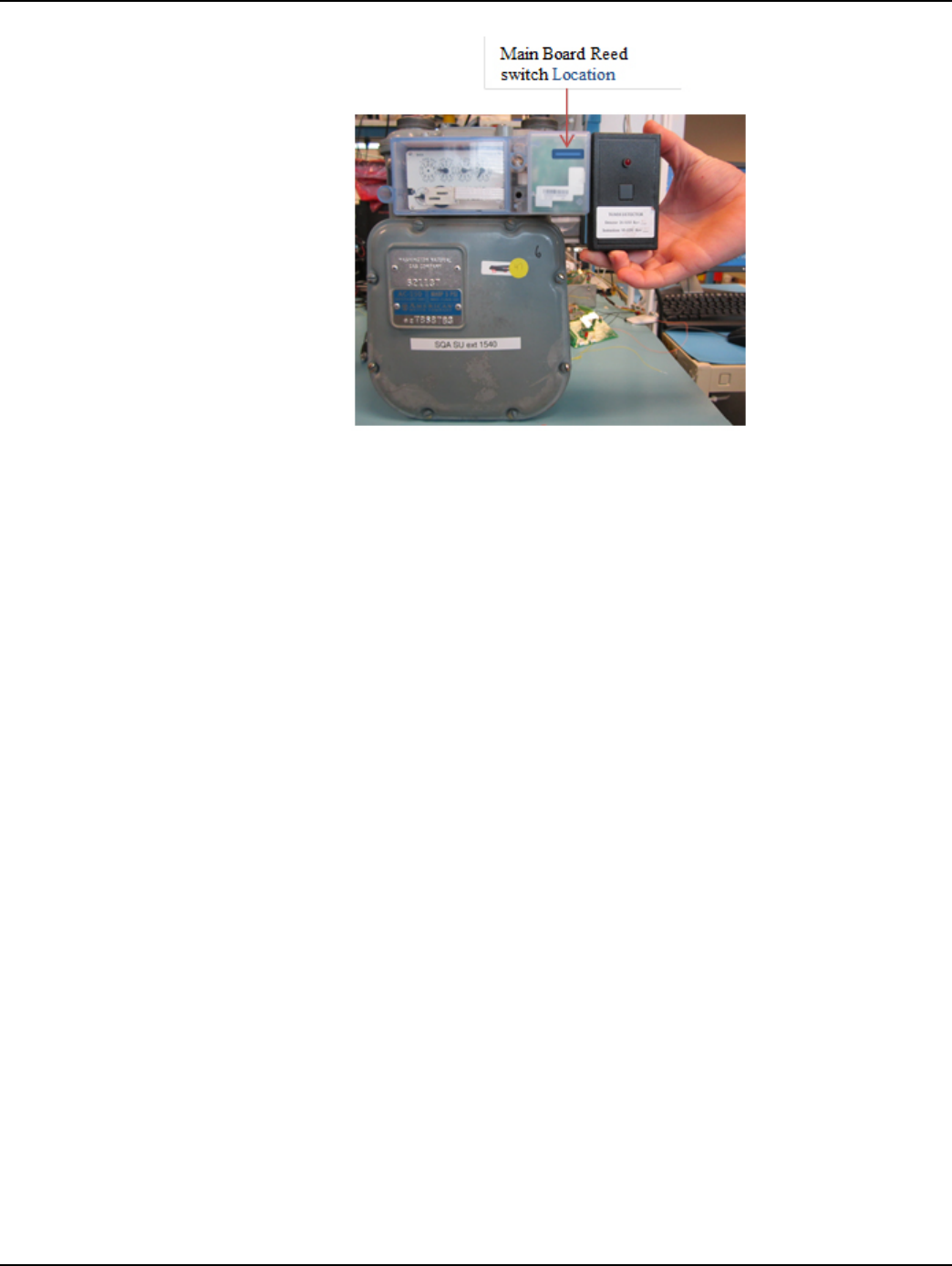
Landis+Gyr Chapter 8 - Dresser Roots Installation
Installation Guide 98-1135 Rev AB 107
Figure 8 - 18. Main Board Reed Switch Location
Field Programming and Data Collection
Field programming and data collection will be done with the Endpoint Testing Manager tool. Please
refer to the Endpoint Testing Manager User Guide, publication 98-1055.
Battery Change Out
When the battery flag (R) is set, it could be due to:
•A single end-point occurrence, where the end-point may require more current to operate. In
this case, a battery in a single endpoint needs to be replaced.
•Occurrence on several end-points, where a battery change out program needs to be
implemented within the following year.
•The flag being set during the coldest part of the day, where the battery may have less than
20% of energy left (2-4 years of service time remaining).
•Occurrence more often even during the daylight hours. In this case, the battery has even less
energy remaining (1-2 years of service time remaining).
To Change Out The Battery
1. Hold a magnet on the magnetic reed switch (about 20 seconds) until the LED flashes one time.
This indicates that the module has been put in sleep mode.
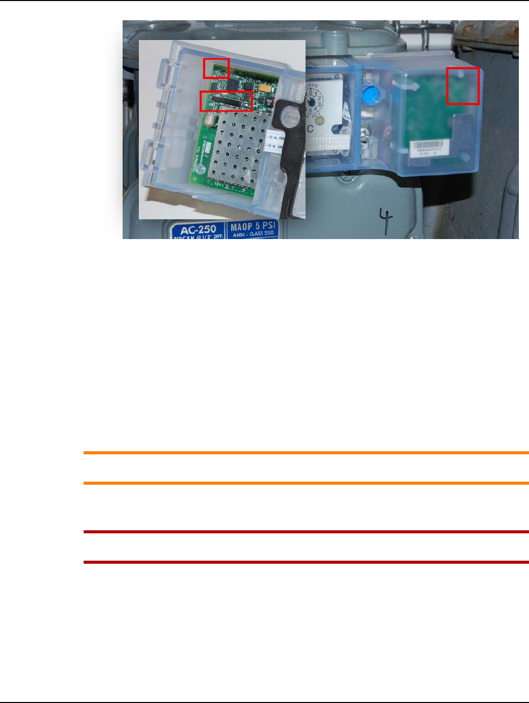
Chapter 8 - Dresser Roots Installation Landis+Gyr
108 98-1135 Rev AB Installation Guide
Figure 8 - 19. LED and Magnetic Reed Switch
2. Remove the meter module mounting screws.
3. Remove the meter module from the meter.
4. Press the snap tabs on the battery door of the module to disengage the door from the module.
5. Remove the suspect battery.
6. Apply electrical insulating compound to circuit board connections.
7. Replace the battery assembly with a new one (battery model #40-1235).
8. Engage the mounting tabs of the battery door with the slots on the battery door.
9. Rotate the battery door onto the module and snap the tab into the slot on the module cover.
10. Install the module onto the gas meter using the four mounting screws.
11. Insert new tamper seals into the housing’s tamper seal wells.
ACAUTION: Once the above steps are completed, it will require at least three hours for all flags
to be cleared (based on two transmissions per hour and Alarm Count = 10).
Connecting the Battery
UWARNING: Substitution of components may impair the suitability for Class I, Division 1
applications. Replace battery only with Landis+Gyr part number 40-1235.
1. Position the module’s battery door so that the battery connector is near the jack and oriented for
connection.
The unit is supplied from the manufacturer with a dab of insulating compound on the circuit
board connector.
2. Push the battery onto the circuit board connector, forcing the battery connector through the
compound, connecting the battery to the module.
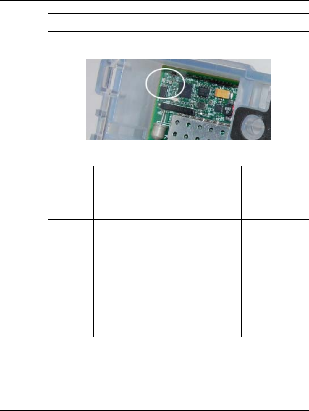
Landis+Gyr Chapter 8 - Dresser Roots Installation
Installation Guide 98-1135 Rev AB 109
NOTE: This module is powered by battery pack part number 40-1235. Battery pack appearance
may vary.
3. Confirm that the LED at the upper right corner (as viewed from outside-front) of the module is
flashing for proper operation. The LED should flash every 5 seconds for one minute.
Figure 8 - 20. Module LED
Applying Water Sealant to Circuit Board Connections
CRC Di-Electric Grease Compound is recommended as a sealant to prevent water intrusion into the
battery circuit board connections.
Table 8 - 4. LED Startup Patterns
Flash Pattern Duration Operational Mode Special Conditions Description
Every 5
seconds 1 minute Installation mode 10 seconds after
battery connection
The radio is operating
normally.
Twic e p er
second Infinite Any mode 1 to 5 minutes after
battery connection
Firmware validation
failed, the module is now
awaiting code download
Twic e p er
second 1 minute Any mode
10 to 20 seconds
after battery
connection
Bad EEPROM data. The
radio will continue to
operate and attempt to
notify the network if left
connected. The unit
should be removed and
returned.
“SOS” once per
minute Infinite Any mode 10 seconds after
battery connection.
The LAN address is
invalid. The radio cannot
operate. The unit must
be removed and
returned.
Every 5
seconds
During the
Config
mode
Configuration mode
10 seconds after
reboot into
configuration mode.
The RF configuration is
active.
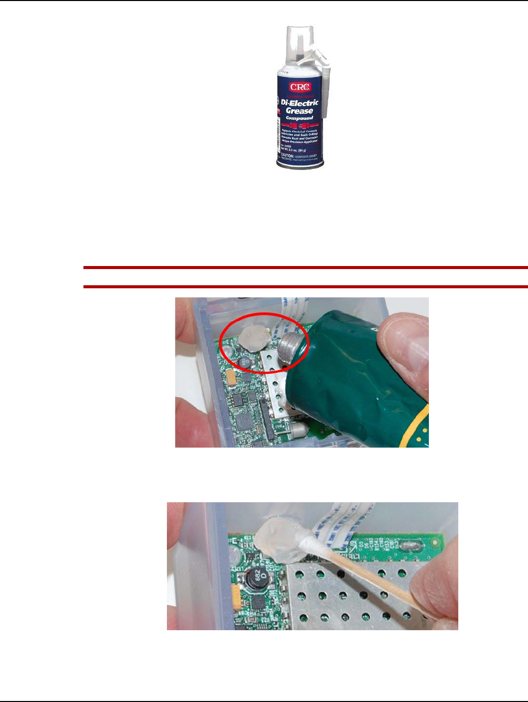
Chapter 8 - Dresser Roots Installation Landis+Gyr
110 98-1135 Rev AB Installation Guide
Figure 8 - 21. 02085 - CRC Di-Electric Grease, Silicone
Novagard® G661 and Dow 4 Insulating Sealant can be used as a sealant to prevent water intrusion
into the battery circuit board connections.
1. Liberally apply CRC Di-Electric Grease Compound, the compound, to the Battery Circuit Board
Connector.
UWARNING: Use of other sealants will void any warranty.
Figure 8 - 22. Apply the Compound to the Battery Connector
2. Force the compound between the connector pins with a cotton tipped swab or other suitable
applicator as shown in the next figure.
Figure 8 - 23. Force the Compound Between Connector Pins
3. Liberally apply the compound to the Battery Interface Cable connector. Use a cotton tipped
swab or other suitable applicator to force the compound into ALL holes and cover ALL
electrical contacts.

Landis+Gyr Chapter 8 - Dresser Roots Installation
Installation Guide 98-1135 Rev AB 111
Figure 8 - 24. Apply the Compound to the Battery Connector: Cover All Contacts
Ordering Information
CRC Di-Electric Grease Compound
Model: 02085
Description: Di-Electric Grease, Silicone, Net 3.3 oz.
Manufacturer:
CRC Industries Americas Group
885 Louis Drive
Warminster, PA 18974-2869
Phone: (215) 674-4300
Email: info@crcindustries.com
Website: http://www.crcindustries.com/
Novagard G661 is available in 5.3 ounce tubes and 1-gallon pails. It has a shelf-life of eighteen (18)
months from the date of manufacture, as indicated by the lot number, when stored in the original,
unopened container at, or below, 100ºF.
Novagard® G661 may be ordered from:
Novagard Solutions®
5109 Hamilton Avenue
Cleveland, OH 44114
Phone: (216) 881-3890 Facsimile: (216) 881-6977
www.Novagard.com
Blank Page
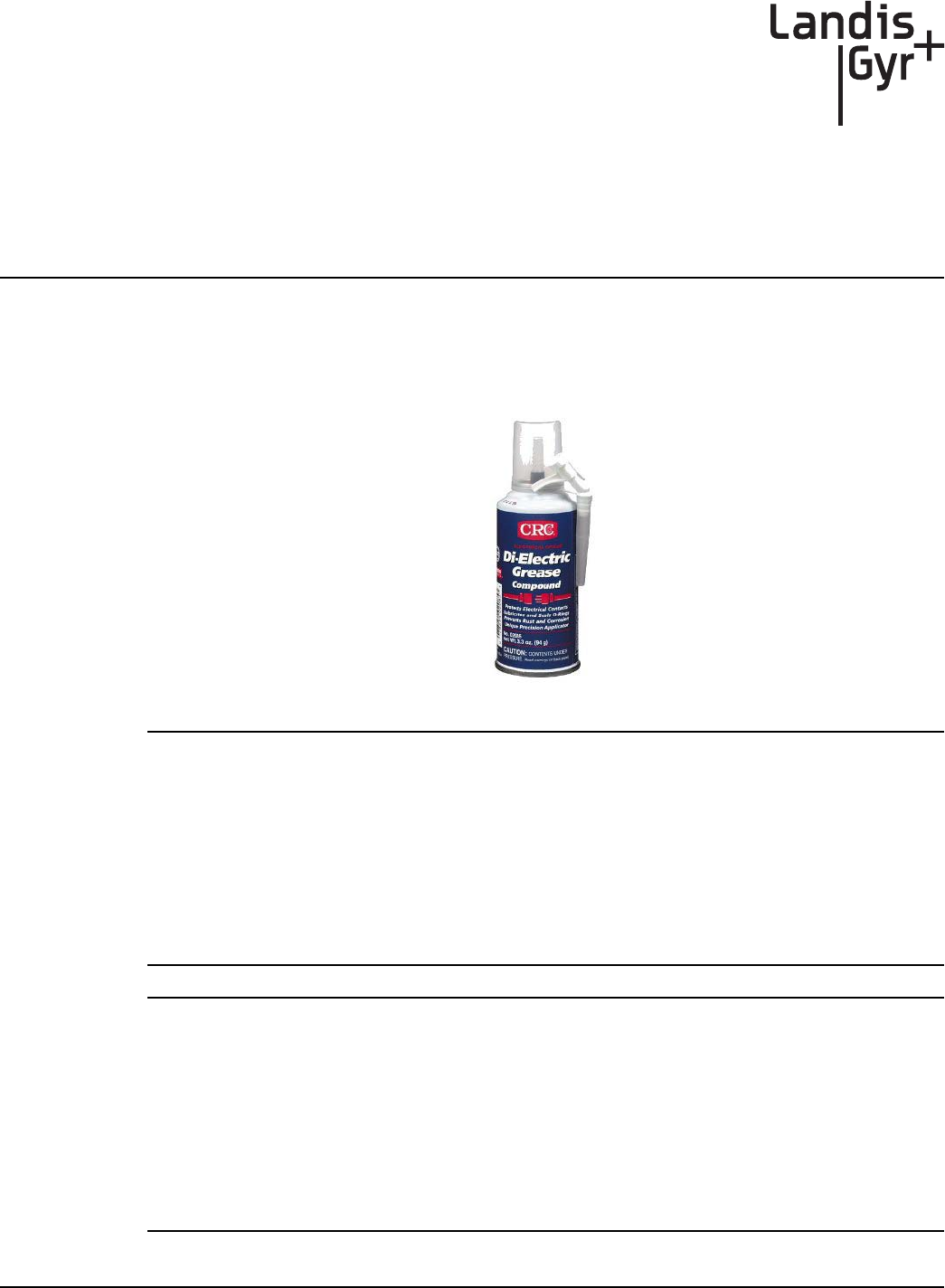
A
Installation Guide 98-1135 Rev AB 113
GPR Waterproofing
Applying Water Sealant to Circuit Board Connections
CRC Di-Electric Grease Compound is recommended as a sealant to prevent water intrusion into the
GPR Pulse Input and Battery circuit board connections.
Figure A - 1. CRC Di-Electric Grease Compound
NOTE: Novagard® G661 is also approved as an electrical sealant and is available in 5.3 ounce
tubes. It has a shelf-life of eighteen (18) months from the date of manufacture, as indicated by the
lot number, when stored in the original, unopened container at, or below, 100ºF.
Novagard® G661 may be ordered from:
Novagard Solutions®
5109 Hamilton Avenue
Cleveland, OH 44114
Phone: (216) 881-3890 Facsimile: (216) 881-6977
www.Novagard.com
NOTE: Dow Corning 4 Electrical Insulating Compound is approved as an electrical sealant and may
be ordered from:
Ellsworth Adhesives
Part #: 4 CMPD 150G TUBE
W129 N10825 Washington Dr.
Germantown, WI 53022
Phone: 1-877-454-9224
Website: http://www.ellsworth.com/Home.html
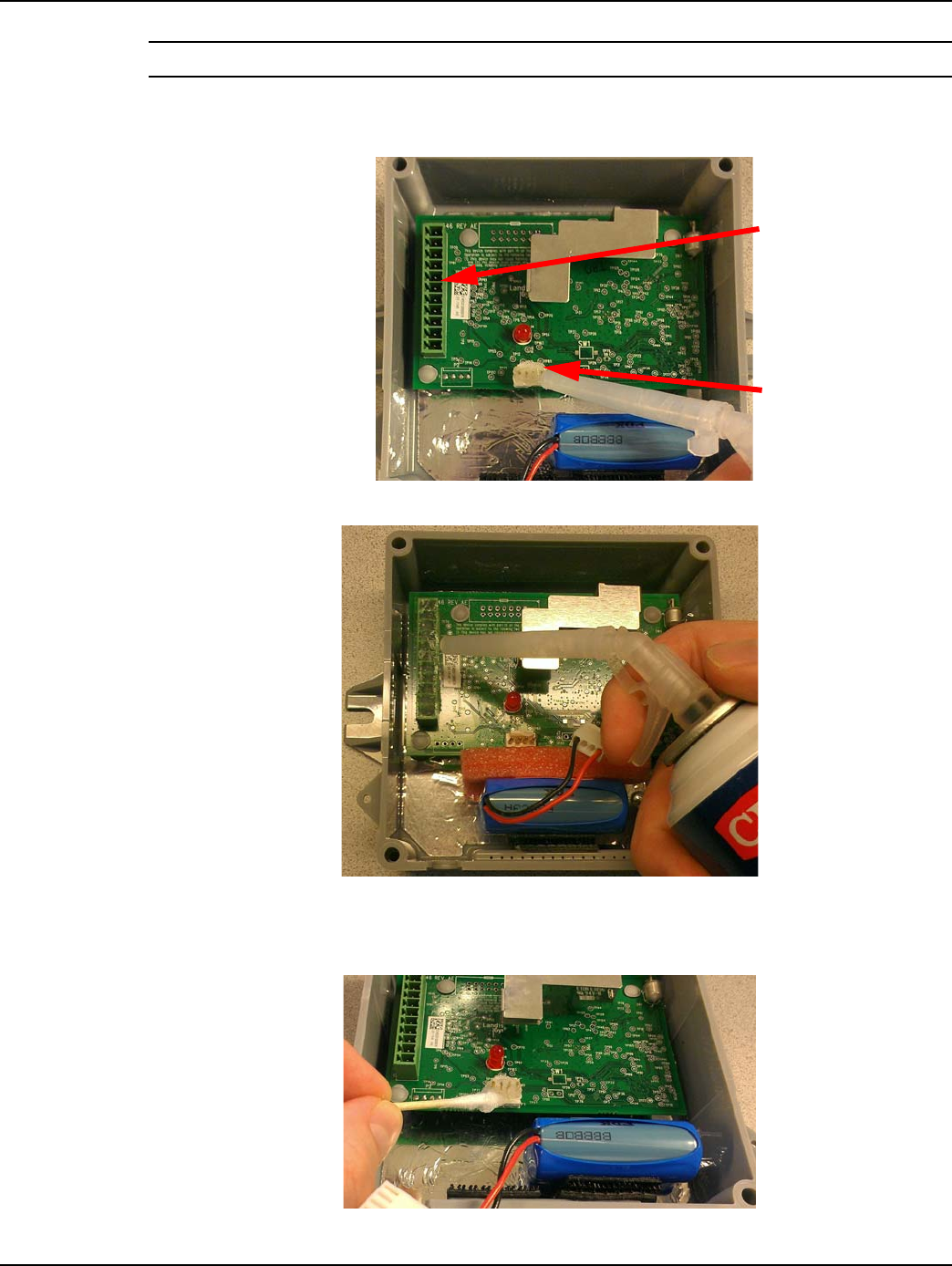
Appendix A - GPR Waterproofing Landis+Gyr
114 98-1135 Rev AB Installation Guide
NOTE: CRC Di-Electric Grease Compound is electrical grade.
1. Liberally apply CRC Di-Electric Grease Compound (“the compound”) to the Battery and GPR
Pulse Input circuit board connectors as shown in Figure A - 2 and Figure A - 3.
Figure A - 2. Apply the Compound to the Battery Connector
Figure A - 3. Apply the Compound to the GPR Pulse Input Connector
2. Force the compound between the connector pins with a cotton tipped swab or other suitable
applicator as shown in Figure A - 4.
Figure A - 4. Force the Compound between Connector Pins
GPR Pulse Input
Connector
Battery Connection
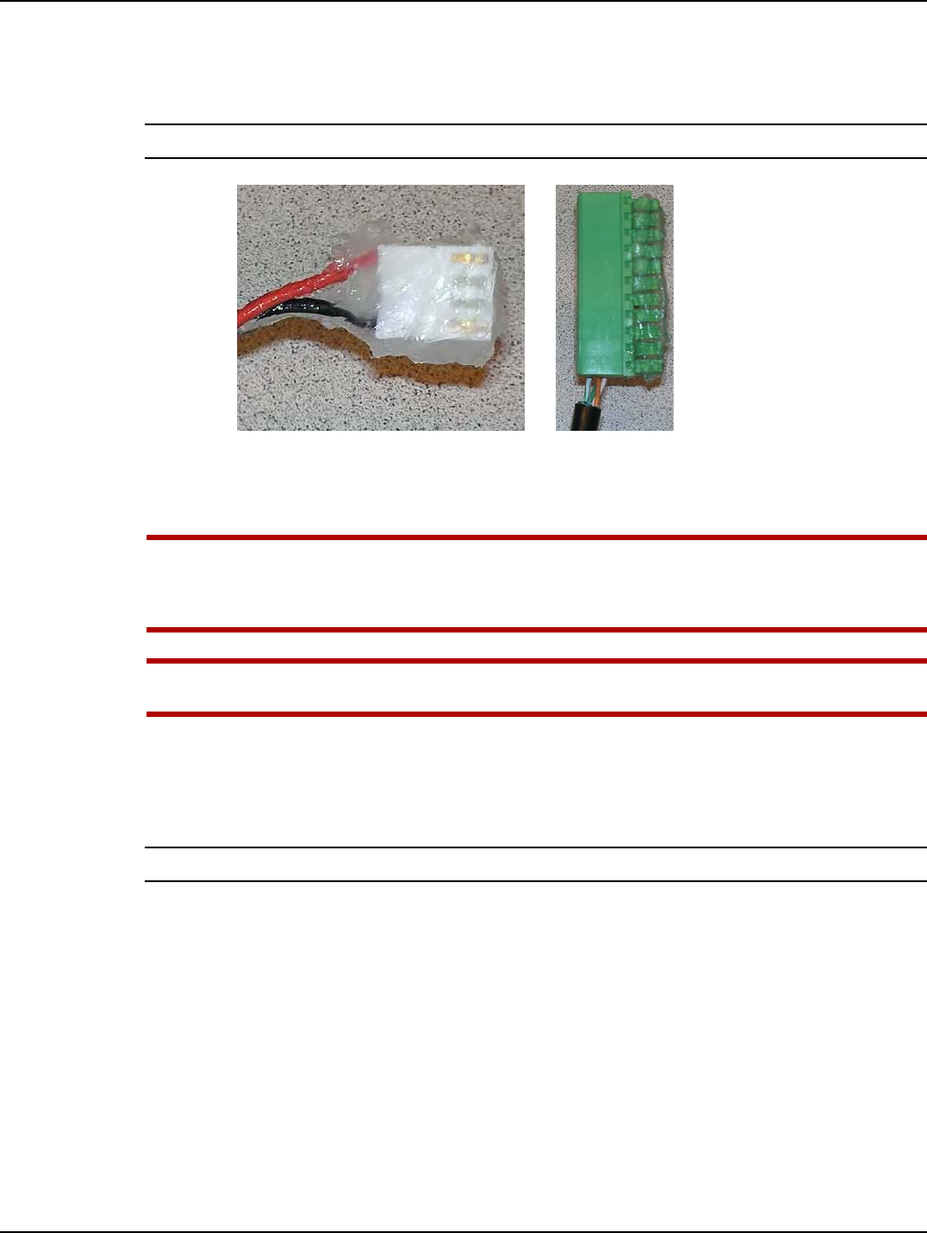
Landis+Gyr Appendix A - GPR Waterproofing
Installation Guide 98-1135 Rev AB 115
3. Liberally apply the compound to the connectors of the GPR Pulse Input and Battery Interface
cables. Force the compound into ALL holes and cover ALL electrical contacts, as shown in the
following photos.
NOTE: The following photos show representative cables to illustrate compound application.
Figure A - 5. Apply the Compound to GPR Cable Connectors: Cover All Contacts
4. First, install the GPR Pulse Input cable, and then the Battery Interface cable, onto the GPR
circuit board connectors as shown in Figure A - 6.
UWARNING: The GPR Pulse Input cable MUST be installed prior to installing the Battery cable.
Do NOT disconnect the Battery cable after it has been installed. Disconnecting the battery
may cause unwanted pulses to be counted by the GPR. If the battery is disconnected,
reprogram the GPR to clear any unwanted pulse counts, then reconnect the battery.
UWARNING: Substitution of components may impair the suitability for Class I, Division 1
applications. Replace battery only with Landis+Gyr part number 40-1235.
5. Liberally apply the compound to the back of each cable connector, forcing the compound into
each hole where the wires exit the connectors. The GPR circuit board and cable connectors must
be completely covered as shown in Figure A - 6. A cotton tipped swab may be used to force the
compound between each wire and into each connector hole.
NOTE: Battery should not be connected until GPR is fully mounted.
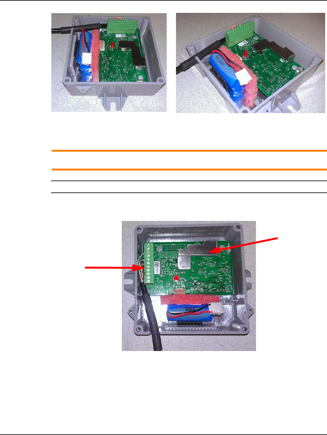
Appendix A - GPR Waterproofing Landis+Gyr
116 98-1135 Rev AB Installation Guide
Figure A - 6. The Compound Must Cover Wires and Connectors for Watertight Seal
6. Arrange the GPR Pulse Input and Battery Interface cables as shown in Figure A - 7. The cables
must not interfere with or block the GPR antenna.
ACAUTION: The GPR Pulse Input cable must be inserted into the GPR enclosure strain relief
slot as shown. The shrink tubing on the cable must be inserted into the strain relief slot.
NOTE: Battery should not be connected until GPR is fully mounted.
7. Gently press the cable downward into the strain relief slot at midpoint of the heat shrink tubing
as shown in the following figures.
Figure A - 7. Arrange Cables As Shown Before Installing the GPR Cover
GPR Pulse
Interface
Cable
GPR Antenna
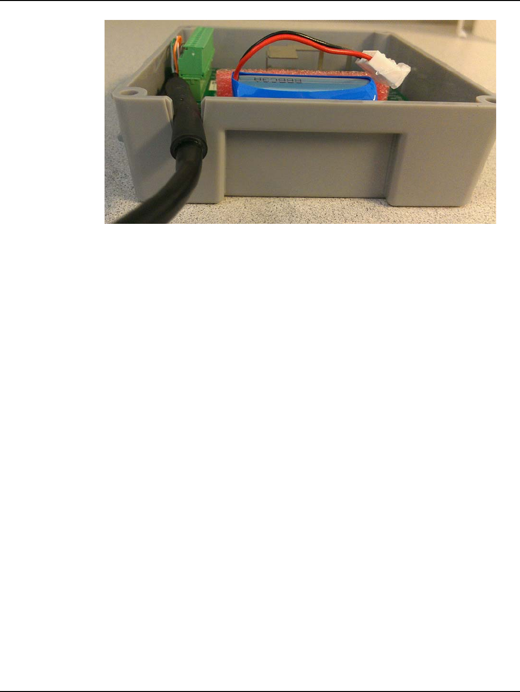
Landis+Gyr Appendix A - GPR Waterproofing
Installation Guide 98-1135 Rev AB 117
Figure A - 8. Heat Shrink Tubing Midpoint Pressed Into Strain Relief Slot

Appendix A - GPR Waterproofing Landis+Gyr
118 98-1135 Rev AB Installation Guide
Ordering Information
CRC Di-Electric Grease Compound
Model: 02085
Description: Di-Electric Grease, Silicone, Net 3.3 oz.
Manufacturer:
CRC Industries Americas Group
885 Louis Drive
Warminster, PA 18974-2869
Phone: (215) 674-4300
Email: info@crcindustries.com
Website: http://www.crcindustries.com/
Novagard® G661 may be ordered from:
Novagard Solutions®
5109 Hamilton Avenue
Cleveland, OH 44114
Phone: (216) 881-3890
Facsimile: (216) 881-6977
www.Novagard.com
Dow Corning 4 Electrical Insulating Compound may be ordered from:
Ellsworth Adhesives
Part #: 4 CMPD 150G TUBE
W129 N10825 Washington Dr.
Germantown, WI 53022
Phone: 1-877-454-9224
Website: http://www.ellsworth.com/Home.html
Cone-Shaped Adhesive Nozzles for Dow 4 Compound may be ordered from:
NOTE: Nozzles listed here have not been tested to verify compatibility with Dow 4 Compound tube
threads. Contact each supplier's customer support for additional information.
3M Collision Repair Solutions
3M™ Threaded Cartridge Nozzle Part Number: 08187
UPC: 00051135081877
Stock Number: 60455034698
http://3mcollision.com/products/tools/applicators-and-accessories/3m-threaded- cartridge-
nozzle-08187.html

Landis+Gyr Appendix A - GPR Waterproofing
Installation Guide 98-1135 Rev AB 119
3M Distributors
http://3mcollision.com/dealers/search?zip=30022&lat=34.029613&lng=- 84.23841700000003
DKHardware.com
Phone: 877-509-8040
CRL Screw-On Uncut Standard Urethane Nozzle
Item # UN0Z
http://www.dkhardware.com/product-11007-un0z-screw-on-uncut-standard-urethane- nozzle.html
Ellsworth Adhesives
W129 N10825 Washington Dr.
Germantown, WI 53022
Phone: 1-877-454-9224
Website: http://www.ellsworth.com/Home.html
•Sika Nozzle - Uncut
•Part #: A4006P - 189429
•Description: Uncut nozzle for adhesive dispensing
Sold as pack (6/pack)
http://www.ellsworth.com/display/productdetail.html?productid=1453&Tab=Vendors
•Sika Nozzle - Threaded Cone
•Part #: 883970 - 169853
•Description: Threaded cone nozzle for adhesive dispensing
Sold as pack (6/pack)
http://www.ellsworth.com/display/productdetail.html?productid=1443&Tab=Vendors
Blank Page

B
Installation Guide 98-1135 Rev AB 121
Installation in Hazardous
Locations
Information
The following information describes and limits what can be attached to the GPR in a Division 1
location per the UL certification.
1. GPR Entity Parameters:
•Uo (Voc) = 6.3 V dc
•Io (Isc) = 7.34 A
•Po = 5.91 W
•Co (Ca) = 207 uF
•Lo (La) = 43 uH
2. The output current of the GPR is limited by a resistor such that the output voltage-current plot is
a straight line drawn between open-circuit voltage and short-circuit current.
3. Selected intrinsically safe equipment must be third party listed as intrinsically safe for the
application, and have intrinsically safe entity parameters conforming to Table B - 1 below.
4. This associated apparatus may also be connected to simple apparatus as defined in Article 504.2
and installed and temperature classified in accordance with article 504.10(B) of the National
Electrical Code (ANSI/NFPA 70), or other local codes, as applicable. The GPRs described in
this guide qualify as simple apparatus for the purposes of intrinsic safety.
5. Capacitance and Inductance of the field wiring from the intrinsically safe equipment to the GPR
shall be calculated and must be included in the system calculation as shown in Table B - 1. Cable
capacitance, Ccable, plus intrinsically safe equipment capacitance, Ci must be less than the
marked capacitance, Ca (or Co), shown on any associated apparatus used. The same applies for
inductance (Lcable, Li and La or Lo, respectively). Where the cable capacitance and inductance
per foot are not known, the following values shall be used: Ccable=60pF/ft., Lcable= 0.2 uH/ft.
The total capacitance and inductance of each I.S. device and associated cable is to be added
together and cannot exceed the stated Co and Lo values.
Table B - 1.
I.S Equipment GPR
Ui (or V max)
or
6.3 V dc
Ii (or I max) 7.34 A
Pi (or P max) 5.91 W
Ci + Ccable 207 uF
Li + Lcable 43 uH

Appendix B - Installation in Hazardous Locations Landis+Gyr
122 98-1135 Rev AB Installation Guide
6. Where multiples circuits extend from the GPR, they must be installed in separate cables or in
one cable having suitable installation. Refer to Article 504.30(B) of the National Electrical Code
(ANSI/NFPA 70) and Instrument Society of American Recommended Practice ISA RP12.6 for
installing intrinsically safe equipment.
7. Intrinsically safe circuit must be wired and separated in accordance with Article 504.20 of the
National Electrical Code (ANSI/NFPA 70) or other local codes, as applicable.
8. The GPR has not been evaluated for use by UL in combination with another associated
apparatus.
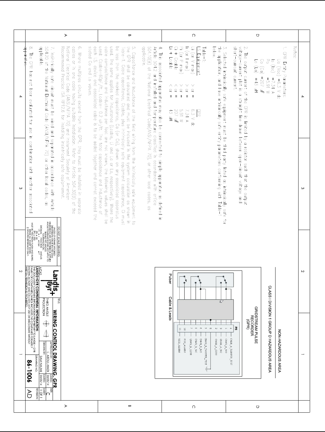
Landis+Gyr Appendix B - Installation in Hazardous Locations
Installation Guide 98-1135 Rev AB 123
Control Drawing 86-1006
Figure B - 1.