Landis Gyr Technology EC6R1S4 GPR2-PT 2-way Gas Module User Manual 15 0053 Exhibit Cover
Landis+Gyr Technology, Inc. GPR2-PT 2-way Gas Module 15 0053 Exhibit Cover
Manual

5015 B.U. Bowman Drive Buford, GA 30518 USA Voice: 770-831-8048 Fax: 770-831-8598
Certification Exhibit
FCC ID: R7PEC6R1S4
FCC Rule Part: 15.247, 15.249
ACS Project Number: 15-0053
Manufacturer: Landis+Gyr Technology, Inc.
Model: GPR2-PT

LANDIS+GYR CONFIDENTIAL INFORMATION
GPR2-PT Installation Guide
Publication: 98-1678 Rev AA

Limitation on Warranties and Liability
Information in this document is subject to change without notice. This manual or any part of it thereof may not be re-
produced in any form unless permitted by contract or by written permission of Landis+Gyr.
In no event will Landis+Gyr be liable for any incidental, indirect, special, or consequential damages (including lost prof-
its) arising out of or relating to this publication or the information contained in it, even if Landis+Gyr has been advised,
knew, or should have known of the possibility of such damages.
© 2015 Landis+Gyr, Inc. All Rights Reserved
GPR2-PT Installation Guide
Publication: 98-1678
Revision History
Modification Date Revision Description Author
03/25/2015 AA Pre-Release Draft Charlie Goerges
Landis+Gyr
Website: www.landisgyr.com
E-mail: solutionsupport.na@landisgyr.com
Technical Support: 1-888-390-5733
© 2015 Landis+Gyr
All rights reserved.

Installation Guide 98-1678 Rev AA 3
Table of Contents
Chapter 1: Pre-Installation . . . . . . . . . . . . . . . . . . . . . . . . . . . . . . . . . . . . . . . . . . . . . . . . . . . . . . . . . . . 5
Before You Begin . . . . . . . . . . . . . . . . . . . . . . . . . . . . . . . . . . . . . . . . . . . . . . . . . . . . . . . . . . . . . . . . . . . . . . . . 5
Safety Overview . . . . . . . . . . . . . . . . . . . . . . . . . . . . . . . . . . . . . . . . . . . . . . . . . . . . . . . . . . . . . . . . . . . . . . . . . 5
FCC Information to the User . . . . . . . . . . . . . . . . . . . . . . . . . . . . . . . . . . . . . . . . . . . . . . . . . . . . . . . . 6
FCC Class B. . . . . . . . . . . . . . . . . . . . . . . . . . . . . . . . . . . . . . . . . . . . . . . . . . . . . . . . . . . . . . . 6
RF Exposure . . . . . . . . . . . . . . . . . . . . . . . . . . . . . . . . . . . . . . . . . . . . . . . . . . . . . . . . . . . . . . 6
Compliance . . . . . . . . . . . . . . . . . . . . . . . . . . . . . . . . . . . . . . . . . . . . . . . . . . . . . . . . . . . . . . . . . . . . . . 6
Preliminary Checks . . . . . . . . . . . . . . . . . . . . . . . . . . . . . . . . . . . . . . . . . . . . . . . . . . . . . . . . . . . . . . . . 7
Site Requirements . . . . . . . . . . . . . . . . . . . . . . . . . . . . . . . . . . . . . . . . . . . . . . . . . . . . . . . . . . . . . . . . . 7
Required Installation Tools . . . . . . . . . . . . . . . . . . . . . . . . . . . . . . . . . . . . . . . . . . . . . . . . . . . . . . . . . . 7
Required Parts . . . . . . . . . . . . . . . . . . . . . . . . . . . . . . . . . . . . . . . . . . . . . . . . . . . . . . . . . . . . . . . . . . . . . . . . . . . 7
Chapter 2: GPR2-PT Mounting Instructions . . . . . . . . . . . . . . . . . . . . . . . . . . . . . . . . . . . . . . . . . . . . . . 9
GPR2-PT Mounting . . . . . . . . . . . . . . . . . . . . . . . . . . . . . . . . . . . . . . . . . . . . . . . . . . . . . . . . . . . . . . . . . . . . . . 9
Installation Instructions . . . . . . . . . . . . . . . . . . . . . . . . . . . . . . . . . . . . . . . . . . . . . . . . . . . . . . . . . . . . . 9
GPR2-PT Mounting Instructions . . . . . . . . . . . . . . . . . . . . . . . . . . . . . . . . . . . . . . . . . . . . . . . . . . . . . . . . . . . 13
Eagle Cable Entry . . . . . . . . . . . . . . . . . . . . . . . . . . . . . . . . . . . . . . . . . . . . . . . . . . . . . . . . . . . . . . . . 13
Serial Connection Wiring Diagram for Eagle Correctors . . . . . . . . . . . . . . . . . . . . . . . . . . . . . . . . . .14
Mercury Cable Entry . . . . . . . . . . . . . . . . . . . . . . . . . . . . . . . . . . . . . . . . . . . . . . . . . . . . . . . . . . . . . .15
Serial Connection Wiring Diagram for Mercury/Honeywell Correctors . . . . . . . . . . . . . . . . . . . . . . . 17
Battery Replacement Procedure . . . . . . . . . . . . . . . . . . . . . . . . . . . . . . . . . . . . . . . . . . . . . . . . . . . . . . 18
Corrector Connection . . . . . . . . . . . . . . . . . . . . . . . . . . . . . . . . . . . . . . . . . . . . . . . . . . . . . . . . . . . . . . . . . . . .19
Mercury Corrector (ERX) . . . . . . . . . . . . . . . . . . . . . . . . . . . . . . . . . . . . . . . . . . . . . . . . . . . . . . . . . . 19
Eagle Corrector (XARTU) . . . . . . . . . . . . . . . . . . . . . . . . . . . . . . . . . . . . . . . . . . . . . . . . . . . . . . . . . . 20
Initial Configuration . . . . . . . . . . . . . . . . . . . . . . . . . . . . . . . . . . . . . . . . . . . . . . . . . . . . . . . . . . . . . . . . . . . . .21
Appendix A: GPR2-PT Waterproofing . . . . . . . . . . . . . . . . . . . . . . . . . . . . . . . . . . . . . . . . . . . . . . . . . . 23
Applying Water Sealant to Circuit Board Connections . . . . . . . . . . . . . . . . . . . . . . . . . . . . . . . . . . . . . . . . . .23
Ordering Information . . . . . . . . . . . . . . . . . . . . . . . . . . . . . . . . . . . . . . . . . . . . . . . . . . . . . . . . . . . . . . . . . . . . 28
Appendix B: Installation in Hazardous
Locations . . . . . . . . . . . . . . . . . . . . . . . . . . . . . . . . . . . . . . . . . . . . . . . . . . . . . . . . . . . . . . . . . . . . . . . . 31
Information . . . . . . . . . . . . . . . . . . . . . . . . . . . . . . . . . . . . . . . . . . . . . . . . . . . . . . . . . . . . . . . . . . . . . . . . . . . . 31

1
Installation Guide 98-1678 Rev AA 5
Pre-Installation
Before You Begin
This text contains the symbols which are explained below.
NOTE: Notes provide important information about products and installation.
ACAUTION: Cautions provide information that you must read to avoid making relatively
moderate errors.
UWARNING: Warnings provide special, must-read information. If you ignore a warning you may
create a safety hazard, omit essential data, or make a critical error.
Safety Overview
NOTE: Proper planning and thorough preparation are critical for successful installation. This
chapter outlines basic requirements for the pre-installation phase.
Prior to starting the installation process, you must develop and launch an installer safety training
plan for initial, refresher, and ongoing safety training. Ensure that installers receive appropriate
initial and refresher training to meet their specific safety-related responsibilities. Installers should be
instructed in the following safety elements as well as any site-specific safety issues.
•New duties for which the installer has not previously received training.
•New processes and methodologies representing new risks that are introduced into the
installation environment.
•Situations where previously unidentified risks are reported.
•Hazard Communication (Employee Right to Know)
•Lifting
•Safe driving
•Use of hand tools
•Confined space
The installation supervisory team assumes responsibility for ensuring that installers are properly
trained, authorized, and continually qualified to perform their work. The team must also take
responsibility for the safety of their installers and to assure safe work methodologies. Installers must

Chapter 1 - Pre-Installation Landis+Gyr
6 98-1678 Rev AA Installation Guide
understand that their supervisor’s responsibility does not relieve them from their individual
responsibility to perform the work safely and to follow all safety rules and procedures applicable to
their work.
FCC Information to the User
Manufacturer: Landis+Gyr
Model Name: GPR2-PT
FCC ID: R7PEC6R1S4
Module Model: GPR2-PT
This device complies with Part 15 of the FCC rules. Operation is subject to the following two
conditions:
1. This device may not cause harmful interference, and
2. This device must accept any interference received, including interference that may cause
undesired operation.
FCC Class B
This equipment has been tested and found to comply with the limits for a Class B digital device,
pursuant to Part 15 of the FCC Rules. These limits are designed to provide reasonable protection
against harmful interference in a residential installation. This equipment generates, uses, and can
radiate radio frequency energy and, if not installed and used in accordance with the Instructions, may
cause harmful interference to radio communications. However, there is no guarantee that
interference will not occur in a particular installation. If this equipment does cause harmful
interference to radio or television reception, which can be determined by turning the equipment off
and on, the user is encouraged to try to correct the interference by one or more of the following
measures:
1. Reorient or relocate the receiving antenna.
2. Increase the separation between the equipment and receiver.
3. Consult Landis+Gyr or an experienced radio technician for help.
UWARNING: Changes or modifications to this device not expressly approved by Landis+Gyr
could void the user's authority to operate the equipment and the product warranty.
RF Exposure
This equipment complies with FCC radiation exposure limits set forth for an uncontrolled
environment. This equipment should be installed and operated with minimum distance 20 cm
between the radiator and your body. This transmitter must not be co-located or operating in
conjunction with any other antenna or transmitter.
Compliance
This apparatus is suitable for Class I, Division 2, Group D Hazardous Locations.

Landis+Gyr Chapter 1 - Pre-Installation
Installation Guide 98-1678 Rev AA 7
UWARNING: Substitution of components may impair the suitability for Class I, Division 2
applications. Replace battery only with Landis+Gyr part number 40-1235.
Substitution of components may impair intrinsic safety. Please refer to the notes in Appendix B for
connecting to this intrinsically safe device.
Preliminary Checks
1. The installer will verify correct site, as specified on work order.
2. The installer will verify that the site is safe for installer activity and equipment.
3. The installer will notify the customer of installer presence and activity, telling the customer that
meter access is required. If necessary, the installer will have the customer sign the work order.
4. When installing meters, the installer will follow guidelines issued by the utility in addition to
those given in this guide.
5. The installer will never perform an installation during a lightning storm or under excessively wet
conditions.
Site Requirements
The site must comply with the following criteria:
1. There is no chance that another object will be set over the antenna.
Required Installation Tools
Recommended Torque Driver Source:
Mountz
1080 N. 11th St. San Jose, CA 95112
Phone: 877-833-1704 or 408-292-2214
Fax: 408-292-2733
e-mail: sales@mountztorque.com
Required Parts
All installations will require the GPR2-PT module (40-2424), serial communication cable (19-2380),
and pipe-mount kit (45-2478).
Some installations might require an optional cable conduit.
Table 1-1. Typical Gas Meter Module Installation Tool List
Torx Pin Head Driver, T10 Phillips Driver, #2
Torque Driver, 0.5in-lbs to 20in-lbs Torque Wrench (Crowfoot), 20in-lbs
to 60in-lbs
Standard Flathead Driver Small Flathead for Screw Terminal
Slip Joint Pliers
2
Installation Guide 98-1678 Rev AA 9
GPR2-PT Mounting
Instructions
GPR2-PT Mounting
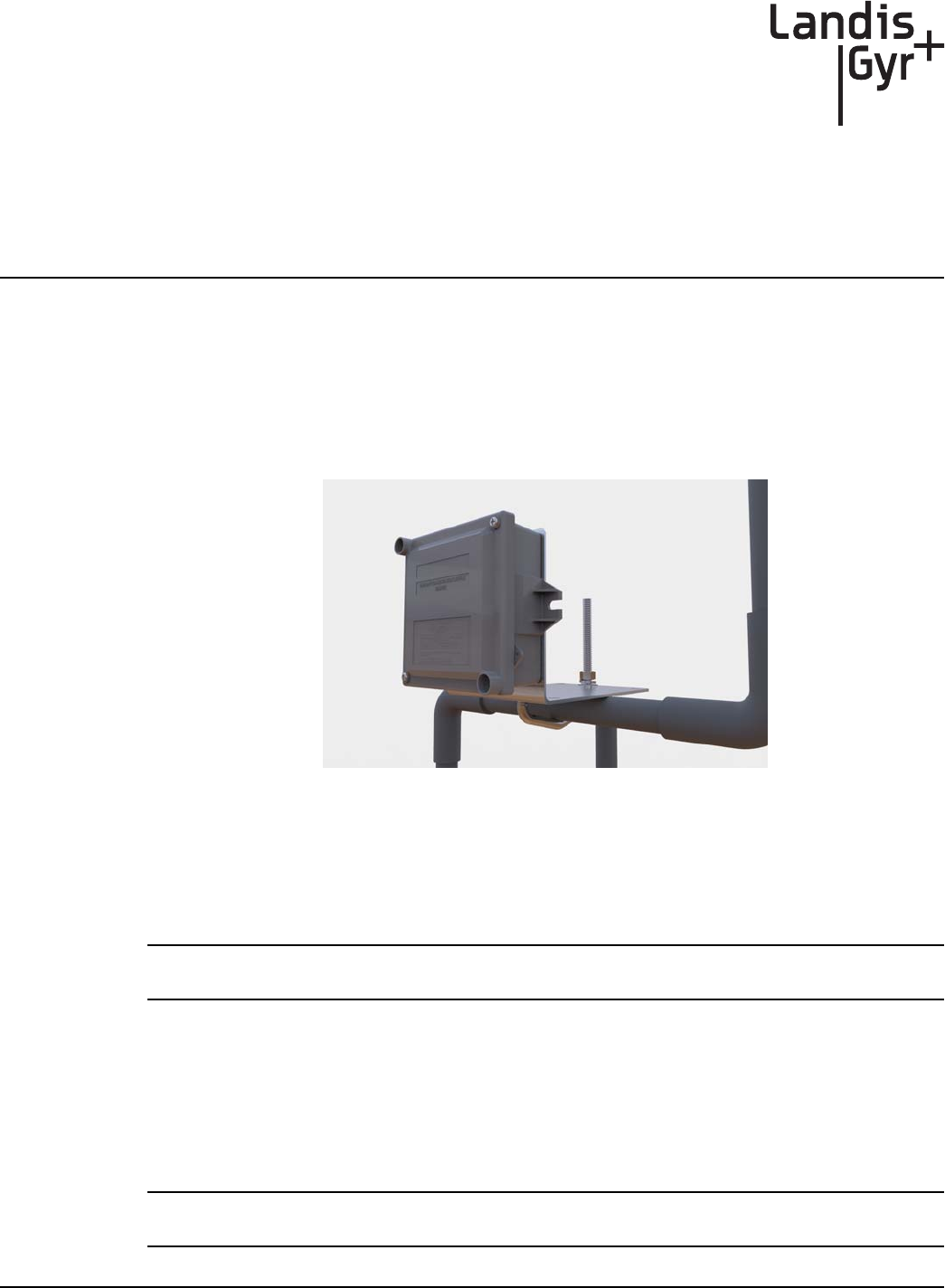
The GPR2-PT module will be mounted vertically and upright, on a pipe-mounting bracket in
proximity to the EVC, to minimize the cable length. This bracket can accommodate pipe diameters
in the range of 1" to 3.25". Optionally, the GPR2-PT can be mounted on a nearby vertical surface.
The cable will be routed in order to minimize its exposure to possible damage. Figure 1 below shows
a typical installation.
Figure 2 - 1. GPR2-PT Mounting Example
Installation Instructions
1. Find a mounting location on a pipe near the EVC. Attach the GPR2-PT enclosure to the
mounting bracket as shown in the following figures.
NOTE: The GPR2-PT must face away from nearby walls and should be installed in a location
unobstructed by gas pipes.
A. Determine whether the GPR2-PT is to be installed on a horizontal or vertical pipe.
•Figure 2 - 4 shows an example bracket orientation for horizontal pipe installations.
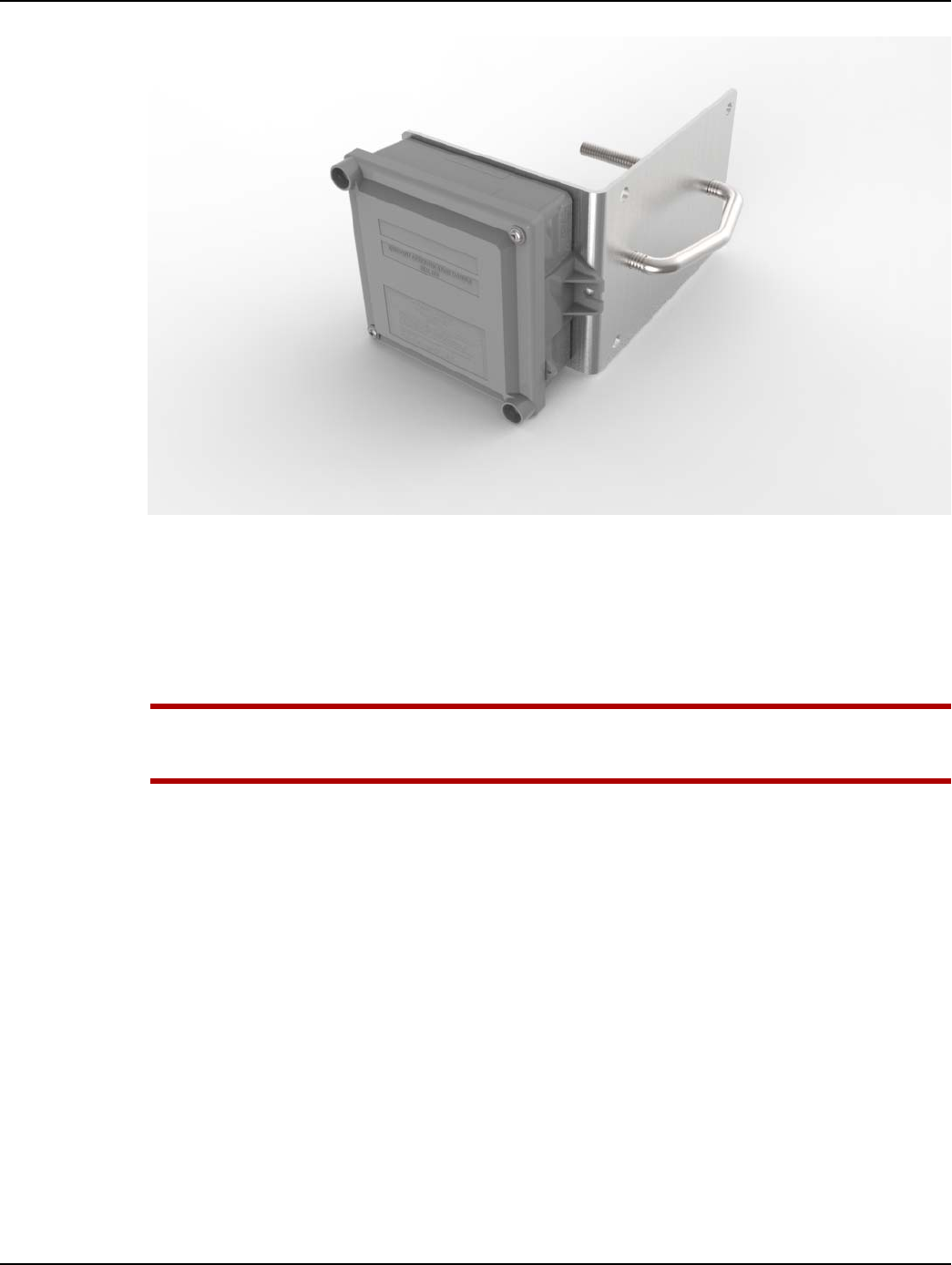
•Figure 2 - 5 shows an example bracket orientation for vertical pipe installations.
B. Attach the GPR2-PT enclosure to the L-shaped bracket through the smaller holes with four
6-20 x ½ inch security Torx screws from the GPR2-PT Pipe Mounting Kit (45-2478).
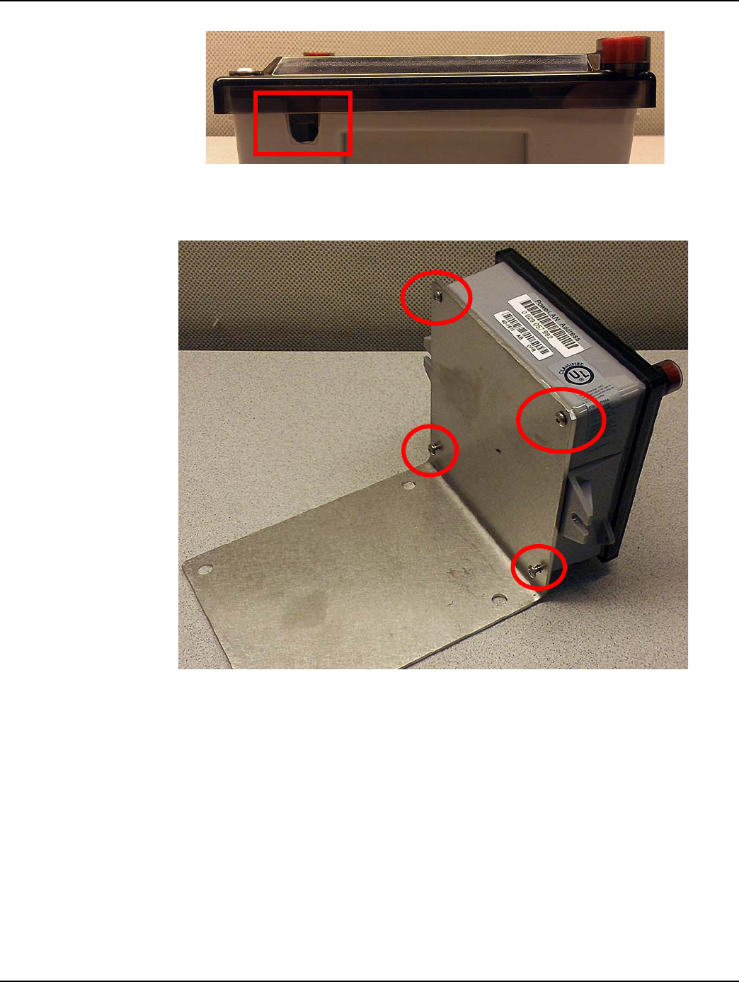
NOTE: The GPR2-PT must be installed on the bracket with the cable entry notch located at the
BOTTOM of the enclosure to prevent dirt and moisture from collecting inside the enclosure.
Chapter 2 - GPR2-PT Mounting Instructions Landis+Gyr
10 98-1678 Rev AA Installation Guide
Figure 2 - 2. Enclosure Cable Entry Notch
C. Using a T-10 security Torx driver, tighten the screws to 10 in-lbs (+/- 2 in-lbs). Tighten the
screws using a crisscross pattern to secure the enclosure to the bracket.
Figure 2 - 3. Attach GPR2-PT to Mounting Bracket
Landis+Gyr Chapter 2 - GPR2-PT Mounting Instructions
Installation Guide 98-1678 Rev AA 11
NOTE: The four longer security Torx screws are GPR2-PT enclosure cover screws. Cover screws
are included in the 40-2424 GPR2-PT kit.
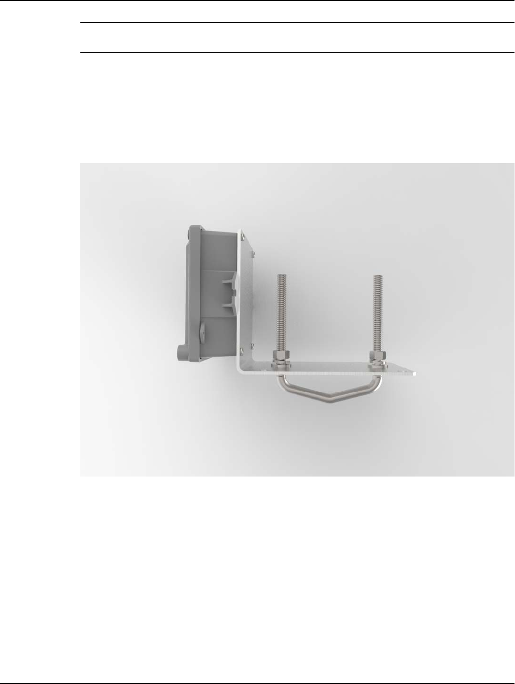
2. Secure the mounting bracket with GPR2-PT to the pipe.
A. Hold the GPR2-PT bracket assembly against the pipe so that the GPR2-PT is vertical and
upright.
B. Insert V-bolt (28-1319) through the 2 middle holes in the bracket (28-0396).
C. Add flat washers, then split-lock washers. Thread nuts over split-lock washers and tighten to
45 +/- 5.0 in-lbs.
Figure 2 - 4. GPR2-PT/Bracket Assembly for Horizontal Pipe Installation
Chapter 2 - GPR2-PT Mounting Instructions Landis+Gyr
12 98-1678 Rev AA Installation Guide
Figure 2 - 5. GPR2-PT/Bracket Assembly for Vertical Pipe Installation
3. Route the serial cable along the most direct and convenient route between the Meter and the
GPR2-PT (preferably along the pipe). Secure the serial cable to the pipe with black nylon UV-
rated tie wraps in locations along the pipe 12" apart.
4. Connect the cable to the EVC using the model-specific instructions below for Eagle or Mercury
EVCs.
UWARNING: Refer to the meter and EVC manufacturers' instructions and warnings on
electrical wiring and electrostatic discharge. Local electrical codes must be followed when
wiring AMR devices in a gas metering environment.
Landis+Gyr Chapter 2 - GPR2-PT Mounting Instructions
Installation Guide 98-1678 Rev AA 13
GPR2-PT Mounting Instructions
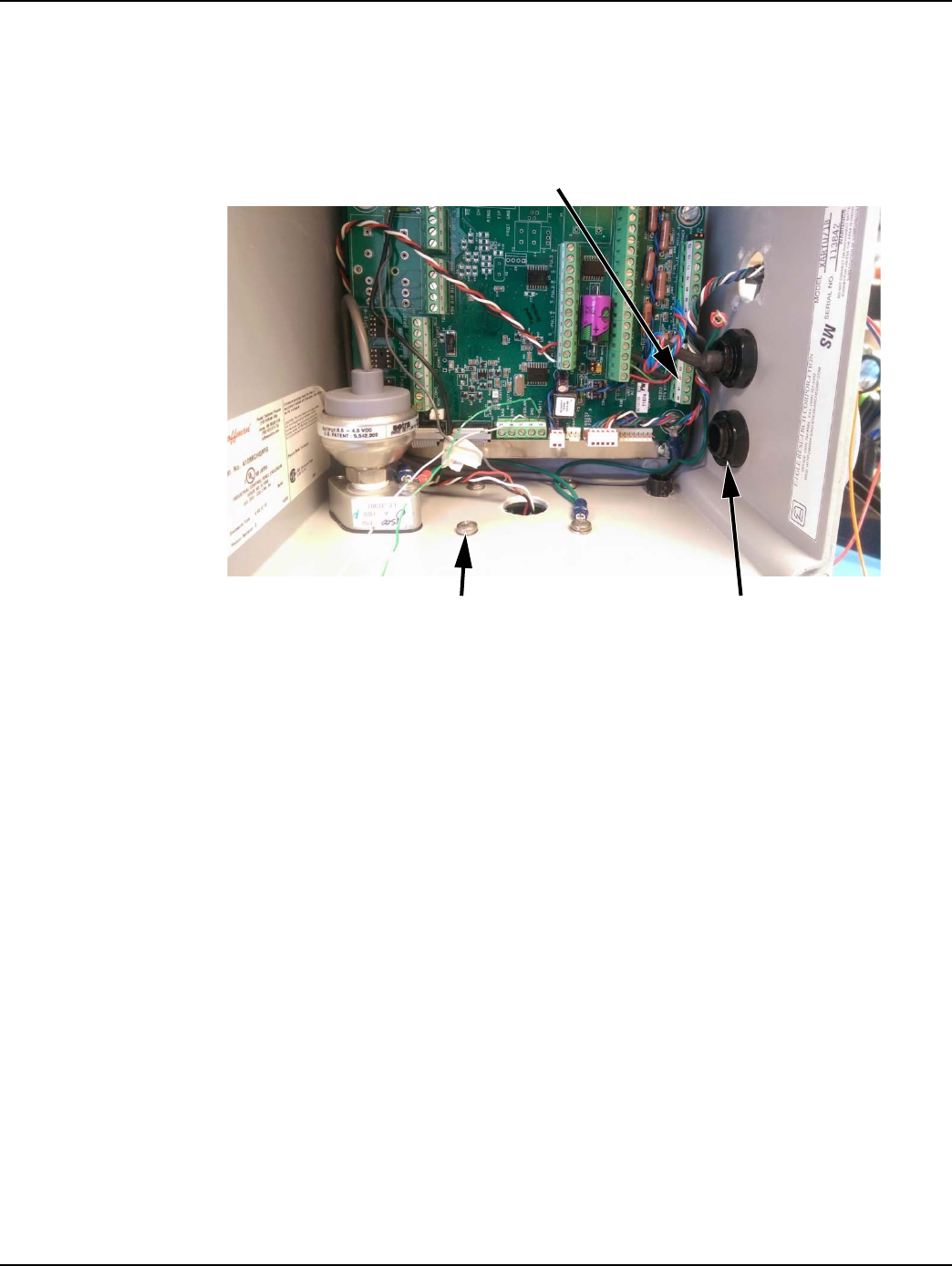
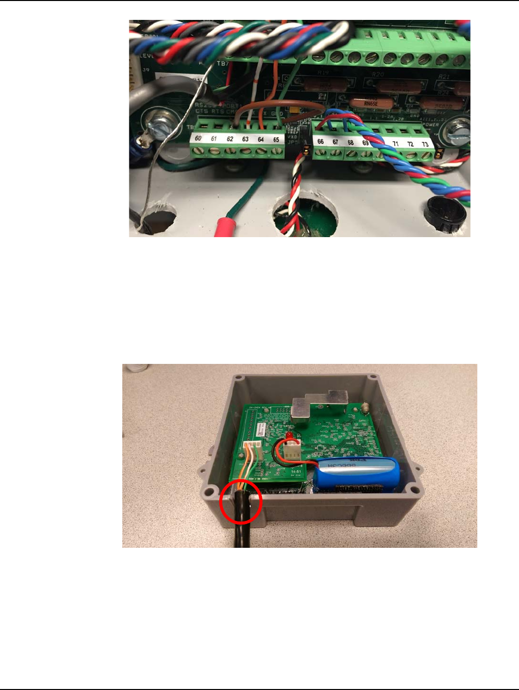
Eagle Cable Entry
Figure 2 - 6. Eagle Corrector Wiring
1. Insert serial cable (19-2380) through cable port shown. If port is filled with a cap, replace with
16-1705 w/ 16-1706 or any similar, water-tight cord grip that will fit a 0.33 inch diameter cable.
2. Pull the cable through the port, far enough to reach the connector and drain hardware.
3. Attach the cable leads into the TB8 connector using a small flathead screwdriver to tighten the
wires. Use the wiring diagram below.
4. Using a Phillips screwdriver, attach the drain terminal to the proper location.
5. Once the connections are secure, make sure the cord grip is sufficiently tightened on the cable.
Connector
Cable PortDrain Screw
Chapter 2 - GPR2-PT Mounting Instructions Landis+Gyr
14 98-1678 Rev AA Installation Guide
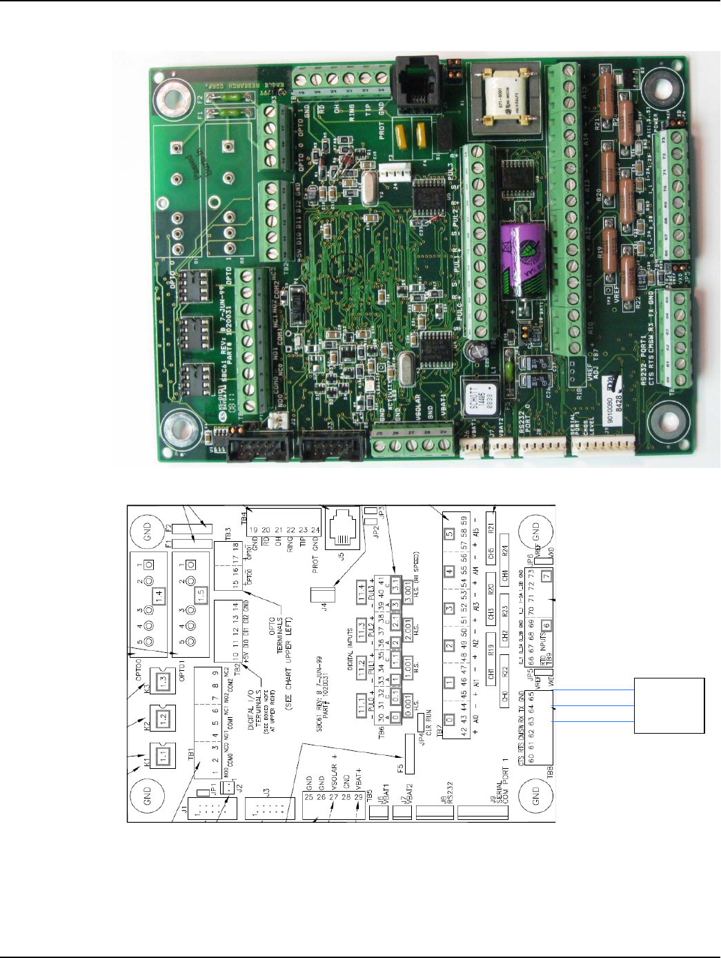
Serial Connection Wiring Diagram for Eagle Correctors
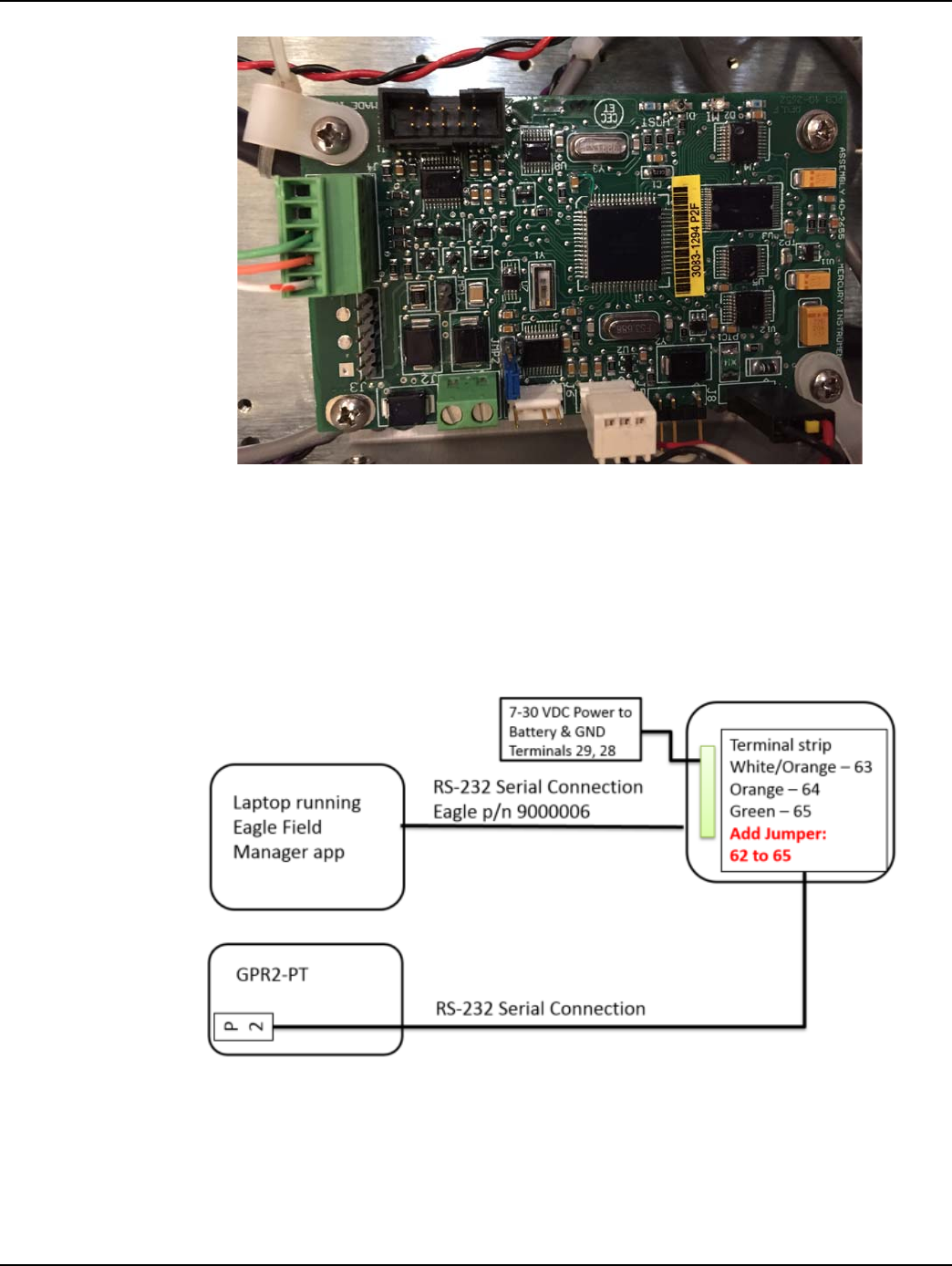
Figure 2 - 7. XARTU Main Board
Figure 2 - 8. Serial Connection Wiring Diagram for XARTU Main Board
1. Once the serial leads and drain terminal are connected, close the EVC. Ensure that no cables are
hanging between the door and the enclosure.
2. Installation is now complete.
Green
Orange
White/Orange
19-2380
Cable
Landis+Gyr Chapter 2 - GPR2-PT Mounting Instructions
Installation Guide 98-1678 Rev AA 15
Mercury Cable Entry
All Mercury EVC models will be retrofitted with the PT-board. This will provide the serial
communication interface to the GPR2-PT.
Although physically different, each model should have unused cable ports as shown in Figure 2 - 9
through Figure 2 - 11 below.
Figure 2 - 9. Mercury ECAT Interior
Figure 2 - 10. Mercury Mini-AT Interior
Chapter 2 - GPR2-PT Mounting Instructions Landis+Gyr
16 98-1678 Rev AA Installation Guide
Figure 2 - 11. Mercury Mini-Max Interior
1. Insert serial cable (19-2380) through the appropriate cable port. If the port is filled with a cap,
replace with 16-1704 or any similar, water-tight cord grip that will fit a 0.33 inch diameter cable
(e.g. Mercury PN 20-8911).
2. Pull the cable through the port far enough to reach the connector and drain hardware.
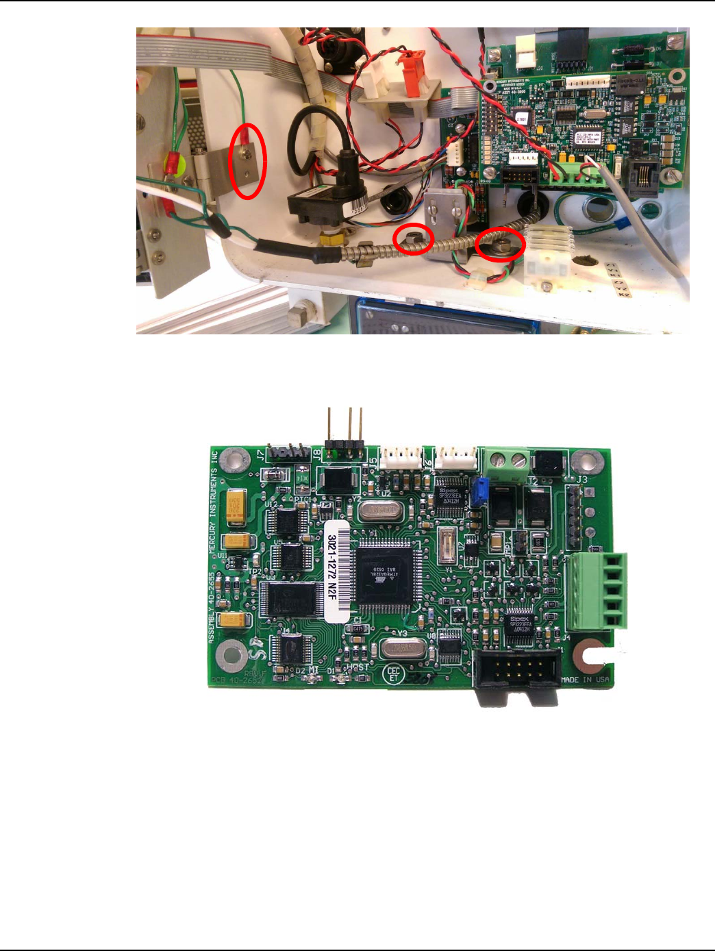
3. Attach the cable leads into the J4 connector of the PT board (Mercury PN 40-3812) using a small
flathead screwdriver to tighten the wires. Use the wiring diagram below.
4. Using a screwdriver or slip joint pliers, attach the drain terminal to an appropriate screw or nut
for proper grounding. Some common examples are shown in Figure 2 - 12 through Figure 2 - 13
below.
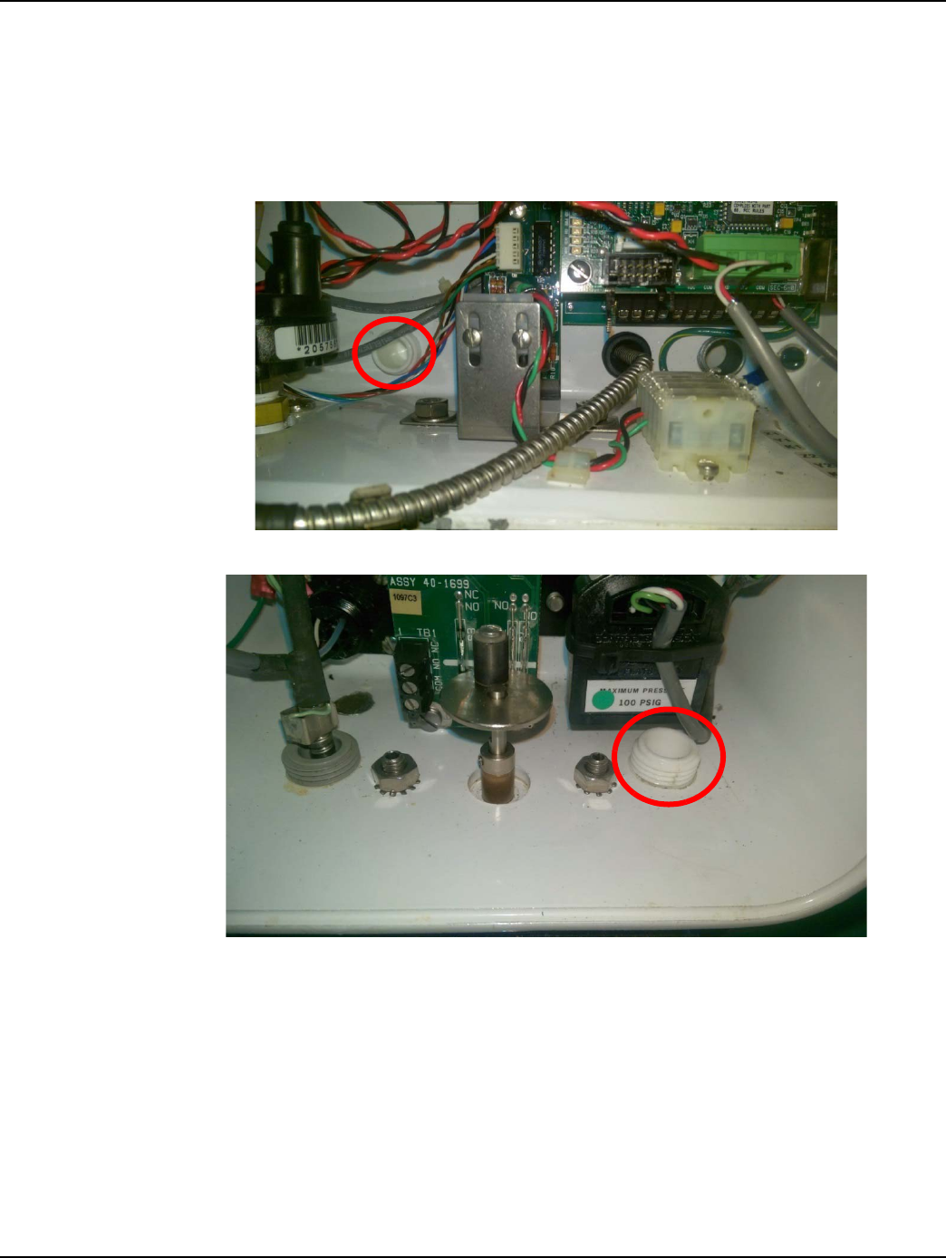
5. Once the connections are secure, make sure the cord grip is sufficiently tightened on the cable.
Figure 2 - 12. Drain Locations in Mini-AT
Landis+Gyr Chapter 2 - GPR2-PT Mounting Instructions
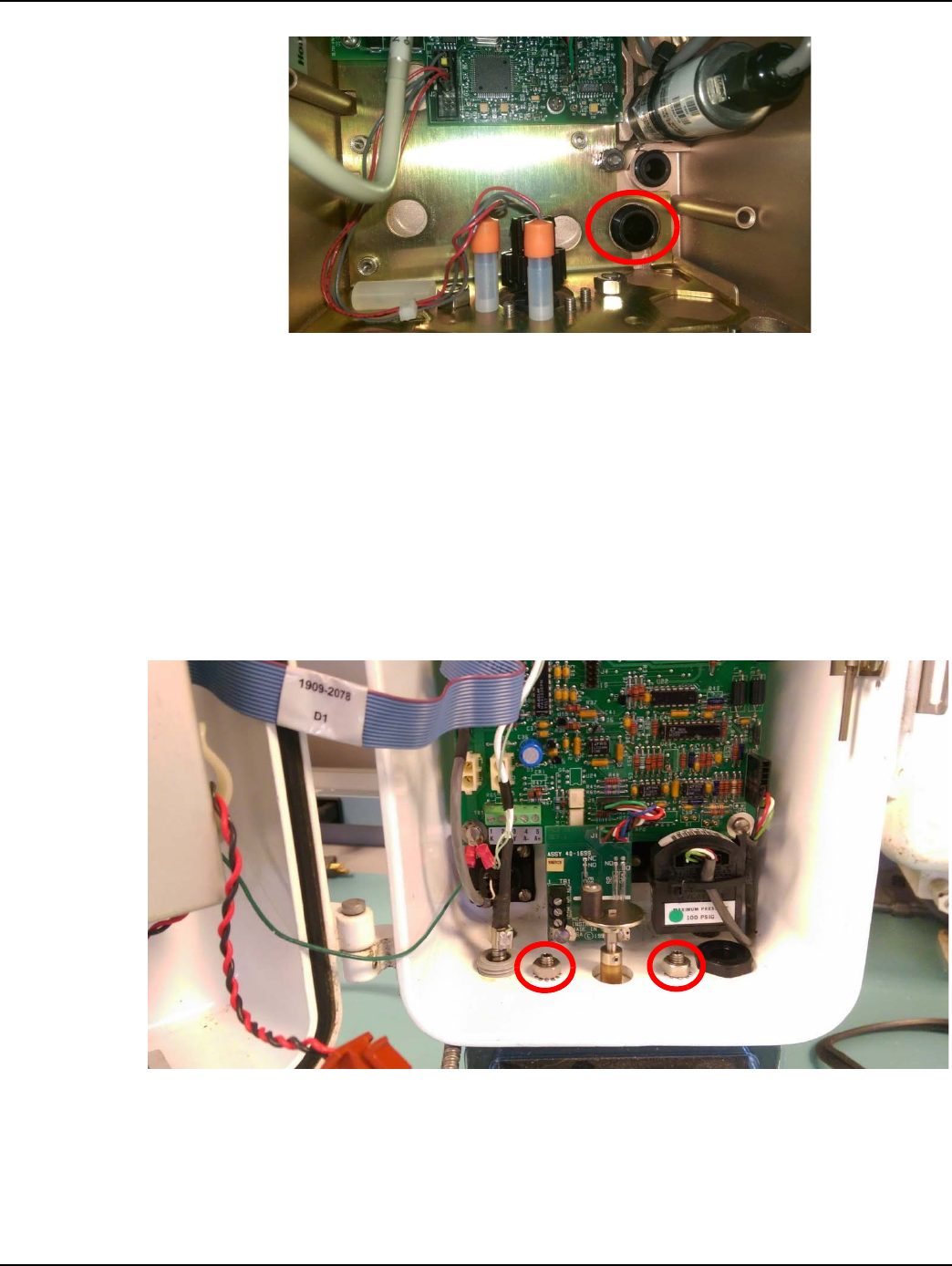
Installation Guide 98-1678 Rev AA 17
Figure 2 - 13. Drain Locations in ECAT
Serial Connection Wiring Diagram for Mercury/Honeywell Correctors
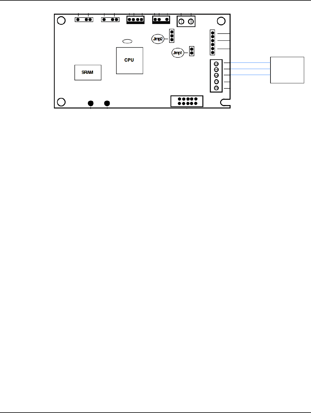
Figure 2 - 14. Protocol (PT) Board
Chapter 2 - GPR2-PT Mounting Instructions Landis+Gyr
18 98-1678 Rev AA Installation Guide
Figure 2 - 15. Serial Connection Wiring Diagram for PT Board
1. Once the serial leads and drain terminal are connected, close the EVC. Ensure that no cables are
hanging between the door and the enclosure.
2. Installation is now complete.
Battery Replacement Procedure
1. To change the battery of the GPR2-PT, first take off the cover by removing the 4 screws with a
Torx T10 pin-head driver.
2. Unplug the dead battery and detach it from the Velcro. Do not hit the PCBA when removing the
battery.
3. Attach the new battery to the Velcro in the same location.
4. Plug the new battery into the same header of the PCBA.
5. Put the cover back onto the enclosure using the same 4 screws with the T10 driver. Torque
screws to 13 inch-pounds (± 1 inch-pound).
6. Ensure the gasket tab is inserted into the strain relief slot that holds the serial cable.
7. Battery replacement is now complete.
Green
Orange
White/Orange
19-2380
Cable
RxD
TxD
GND
Landis+Gyr Chapter 2 - GPR2-PT Mounting Instructions
Installation Guide 98-1678 Rev AA 19
Corrector Connection
Mercury Corrector (ERX)
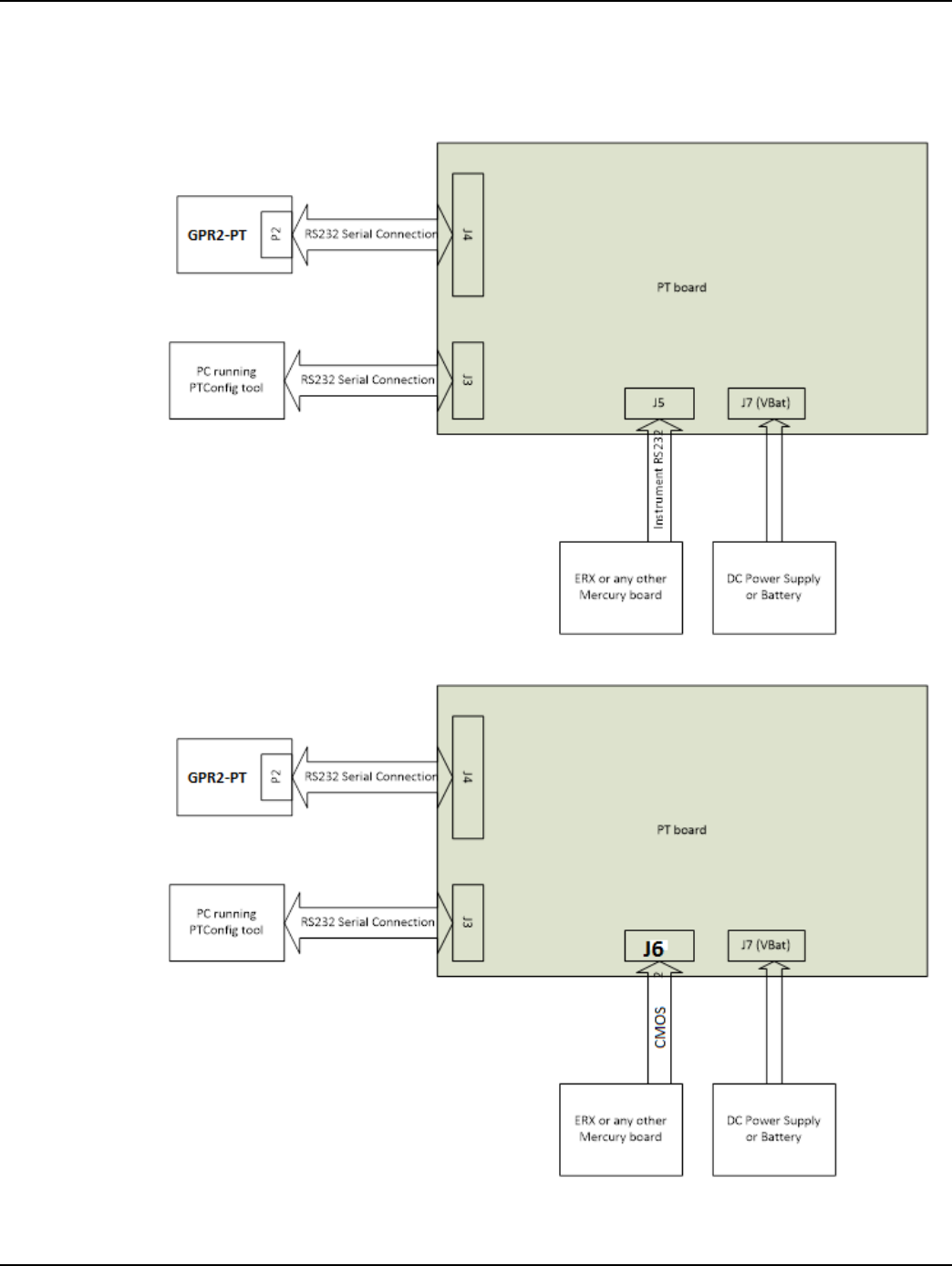
Figure 2 - 16. Mercury Connections Diagram for J5
Figure 2 - 17. Mercury Connections Diagram for J6
Chapter 2 - GPR2-PT Mounting Instructions Landis+Gyr
20 98-1678 Rev AA Installation Guide
Figure 2 - 18. Mercury Connections
To establish a communication between Corrector and GPR2-PT board, all wires should be connected
as described in the diagram from PT board. Mercury's Protocol Translator Configuration software is
required to start communication with Corrector from Laptop/PC. Specific MODBUS configuration
required to initiate communication between Corrector (PT board) and GPR2-PT board.
Eagle Corrector (XARTU)
Figure 2 - 19. Eagle Connections Diagram
Landis+Gyr Chapter 2 - GPR2-PT Mounting Instructions
Installation Guide 98-1678 Rev AA 21
Figure 2 - 20. Eagle Connections
Initial Configuration
To establish a communication between Corrector and GPR2-PT board, all wires should be connected
as described in the diagram. Eagle's Field Manager Tool is required to start communication with
Corrector from Laptop/PC. Specific MODBUS configuration required to initiate communication
between Corrector and GPR2-PT board.
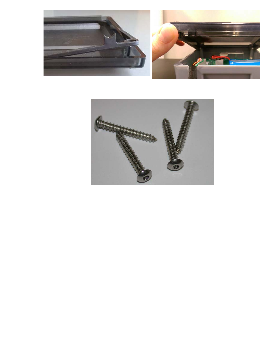
Figure 2 - 21. Serial Cable Must Route Through GPR2-PT Strain Relief Slot
1. Install the GPR2-PT cover using the four security Torx screws included with the GPR2-PT. The
cover must be installed with the gasket tab inserted into the strain relief slot located at the bottom
left corner of the GPR2-PT enclosure as shown in the following photos.
Chapter 2 - GPR2-PT Mounting Instructions Landis+Gyr
22 98-1678 Rev AA Installation Guide
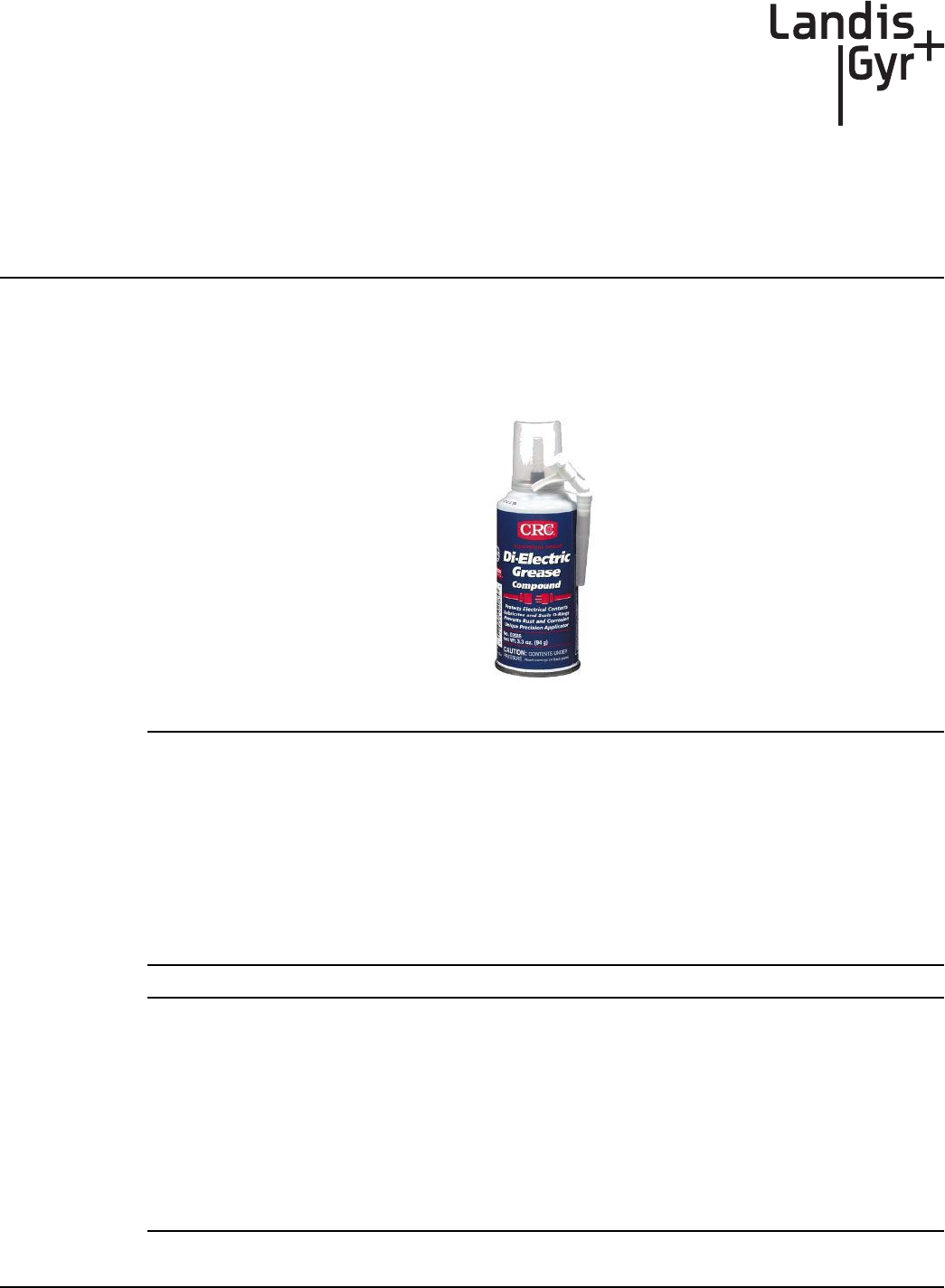
Figure 2 - 22. GPR2-PT Cover Gasket Tab and Cover Strain Relief Slot
2. Tighten the screws to 13 inch-pounds (± 1 inch-pound).
Figure 2 - 23. GPR2-PT Cover Screws
3. Install tamper seals into the tamper cups that are part of the GPR2-PT cover.
4. Installation is now complete.
A
Installation Guide 98-1678 Rev AA 23
GPR2-PT Waterproofing
Applying Water Sealant to Circuit Board Connections
CRC Di-Electric Grease Compound is recommended as a sealant to prevent water intrusion into the
GPR2-PT Pulse Input and Battery circuit board connections.
Figure A - 1. CRC Di-Electric Grease Compound
NOTE: Novagard® G661 is also approved as an electrical sealant and is available in 5.3 ounce
tubes. It has a shelf-life of eighteen (18) months from the date of manufacture, as indicated by the
lot number, when stored in the original, unopened container at, or below, 100ºF.
Novagard® G661 may be ordered from:
Novagard Solutions®
5109 Hamilton Avenue
Cleveland, OH 44114
Phone: (216) 881-3890 Facsimile: (216) 881-6977
www.Novagard.com
NOTE: Dow Corning 4 Electrical Insulating Compound is approved as an electrical sealant and may
be ordered from:
Ellsworth Adhesives
Part #: 4 CMPD 150G TUBE
W129 N10825 Washington Dr.
Germantown, WI 53022
Phone: 1-877-454-9224
Website: http://www.ellsworth.com/Home.html
Appendix A - GPR2-PT Waterproofing Landis+Gyr
24 98-1678 Rev AA Installation Guide
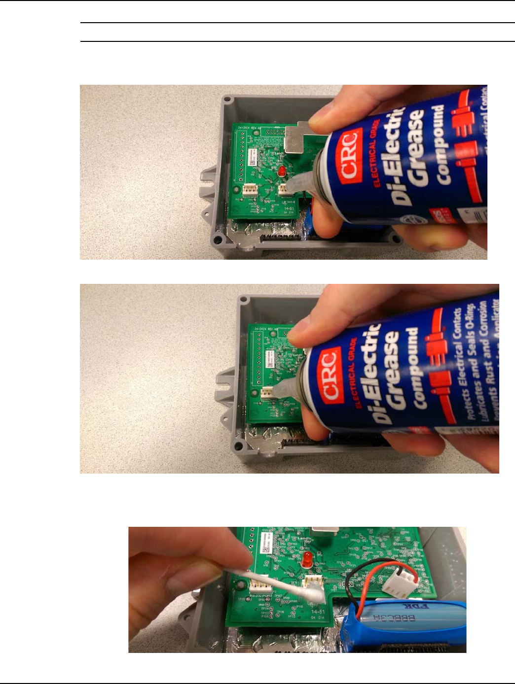
NOTE: CRC Di-Electric Grease Compound is electrical grade.
1. Liberally apply CRC Di-Electric Grease Compound (“the compound”) to the Battery and GPR2-
PT serial connectors as shown in Figure A - 2 and Figure A - 3.
Figure A - 2. Apply the Compound to the Battery Connector
Figure A - 3. Apply the Compound to the GPR2-PT Pulse Input Connector
2. Force the compound between the connector pins with a cotton tipped swab or other suitable
applicator as shown in Figure A - 4.
Figure A - 4. Force the Compound between Connector Pins
Landis+Gyr Appendix A - GPR2-PT Waterproofing
Installation Guide 98-1678 Rev AA 25
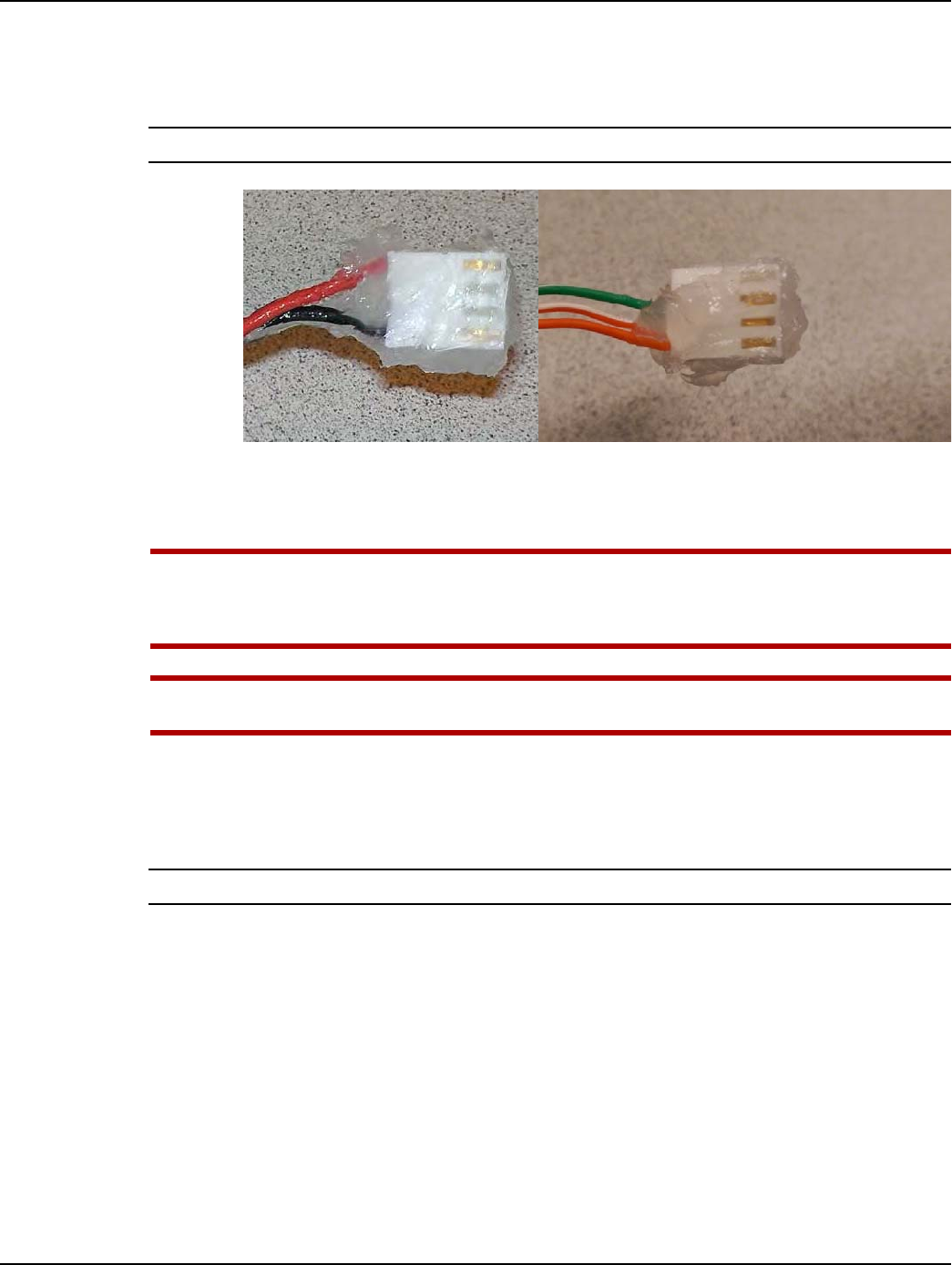
3. Liberally apply the compound to the connectors of the GPR2-PT serial and battery interface
cables. Force the compound into ALL holes and cover ALL electrical contacts, as shown in the
following photos.
NOTE: The following photos show representative cables to illustrate compound application.
Figure A - 5. Apply the Compound to GPR2-PT Cable Connectors: Cover All Contacts
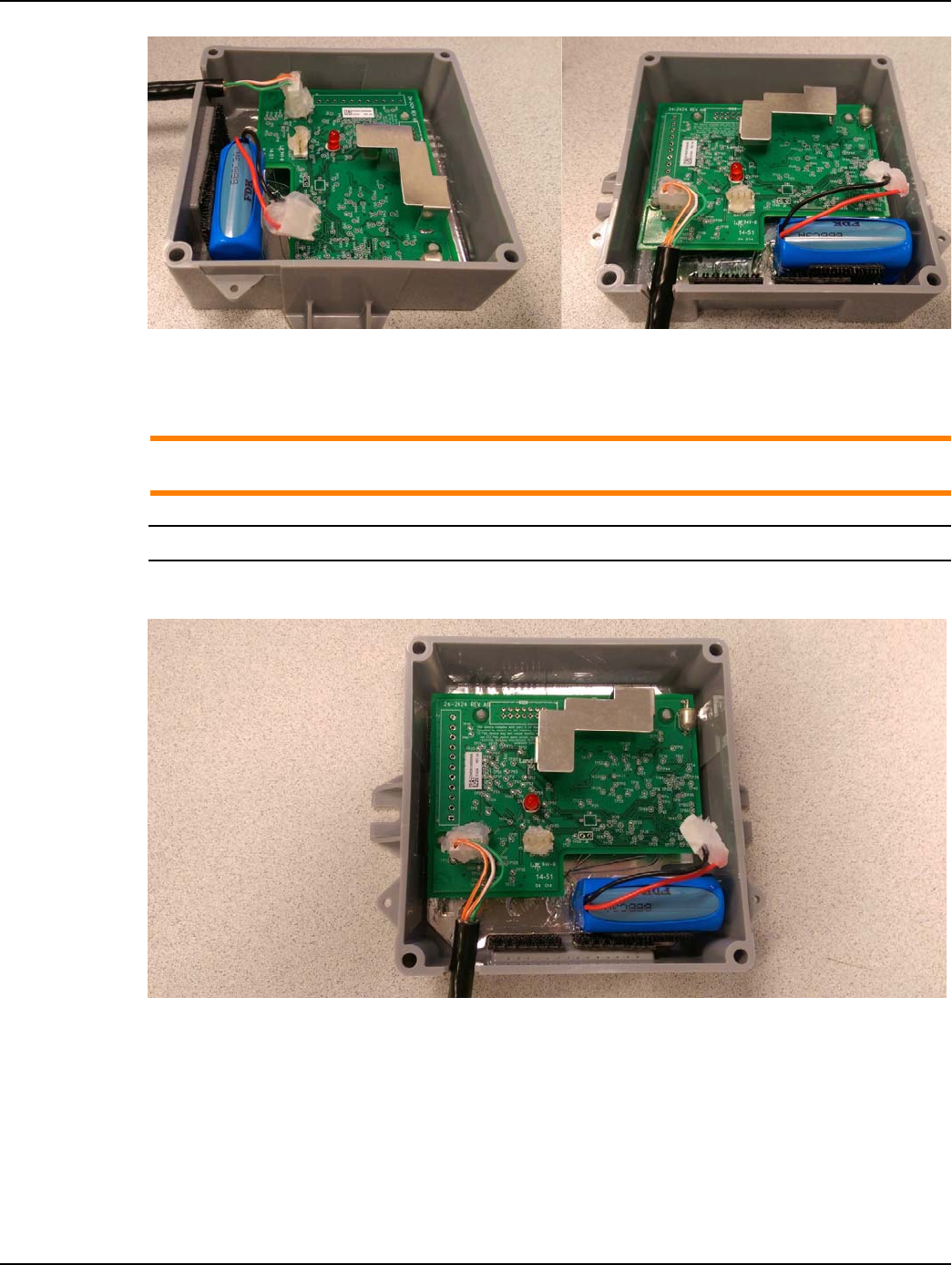
4. First, install the GPR2-PT serial cable, and then the battery interface cable, onto the GPR2-PT
circuit board connectors as shown in Figure A - 6.
UWARNING: The GPR2-PT serial cable MUST be installed prior to installing the battery cable.
Do NOT disconnect the battery cable after it has been installed. Disconnecting the battery
may cause unwanted pulses to be counted by the GPR2-PT. If the battery is disconnected,
reprogram the GPR2-PT to clear any unwanted pulse counts, then reconnect the battery.
UWARNING: Substitution of components may impair the suitability for Class I, Division 2
applications. Replace battery only with Landis+Gyr part number 40-1235.
5. Liberally apply the compound to the back of each cable connector, forcing the compound into
each hole where the wires exit the connectors. The GPR2-PT circuit board and cable connectors
must be completely covered as shown in Figure A - 6. A cotton tipped swab may be used to
force the compound between each wire and into each connector hole.
NOTE: Battery should not be connected until GPR2-PT is fully mounted.
Appendix A - GPR2-PT Waterproofing Landis+Gyr
26 98-1678 Rev AA Installation Guide
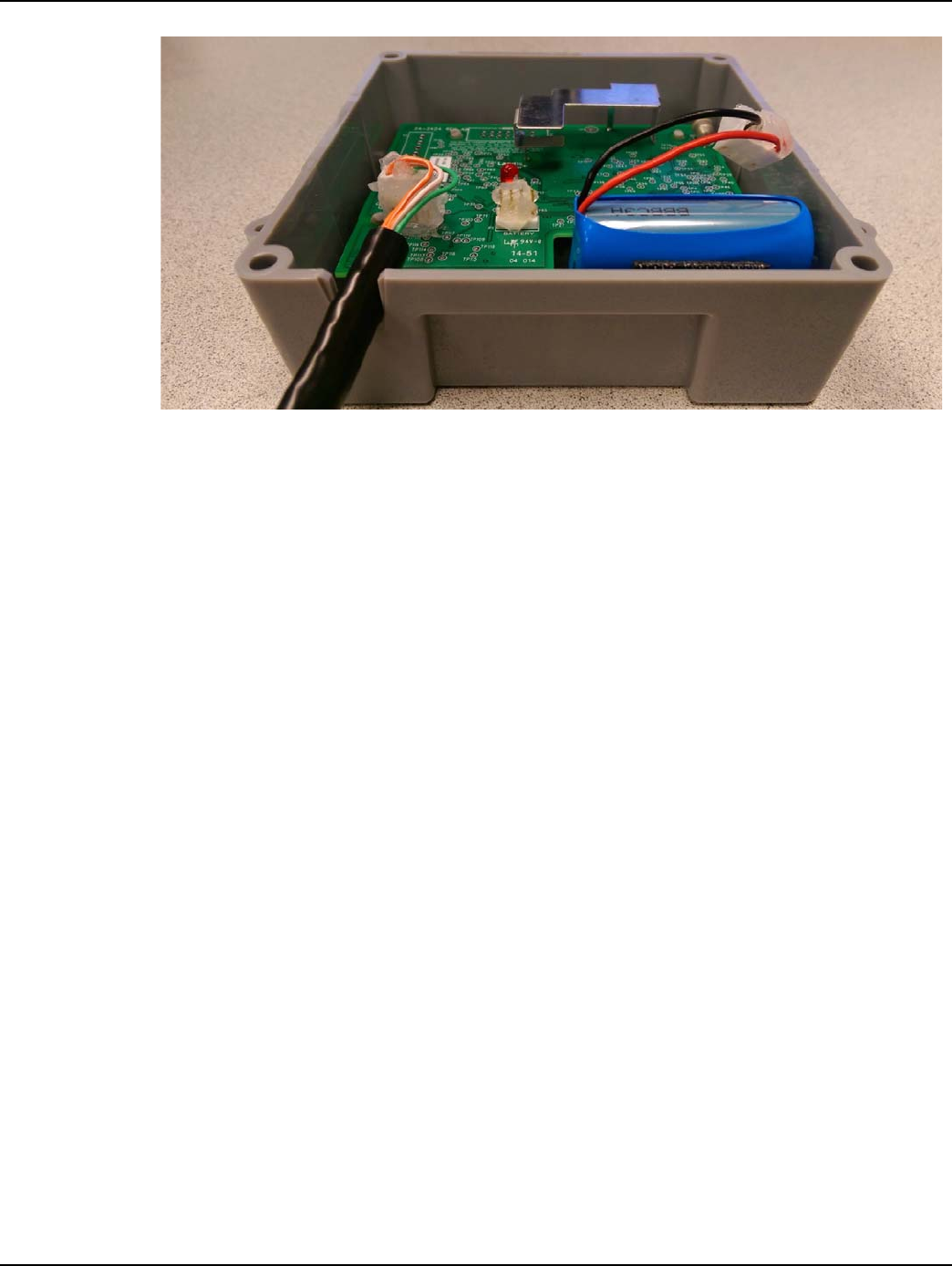
Figure A - 6. The Compound Must Cover Wires and Connectors for Watertight Seal
6. Arrange the GPR2-PT serial and battery interface cables as shown in Figure A - 7. The cables
must not interfere with or block the GPR2-PT antenna.
ACAUTION: The GPR2-PT serial cable must be inserted into the GPR2-PT enclosure strain
relief slot as shown.
NOTE: Battery should not be connected until GPR2-PT is fully mounted.
7. Gently press the cable downward into the strain relief slot as shown in the following figures.
Figure A - 7. Arrange Cables As Shown Before Installing the GPR2-PT Cover
Landis+Gyr Appendix A - GPR2-PT Waterproofing
Installation Guide 98-1678 Rev AA 27
Figure A - 8. GPR2-PT Serial Cable Pressed Into Strain Relief Slot

Appendix A - GPR2-PT Waterproofing Landis+Gyr
28 98-1678 Rev AA Installation Guide
Ordering Information
CRC Di-Electric Grease Compound
Model: 02085
Description: Di-Electric Grease, Silicone, Net 3.3 oz.
Manufacturer:
CRC Industries Americas Group
885 Louis Drive
Warminster, PA 18974-2869
Phone: (215) 674-4300
Email: info@crcindustries.com
Website: http://www.crcindustries.com/
Novagard® G661 may be ordered from:
Novagard Solutions®
5109 Hamilton Avenue
Cleveland, OH 44114
Phone: (216) 881-3890
Facsimile: (216) 881-6977
www.Novagard.com
Dow Corning 4 Electrical Insulating Compound may be ordered from:
Ellsworth Adhesives
Part #: 4 CMPD 150G TUBE
W129 N10825 Washington Dr.
Germantown, WI 53022
Phone: 1-877-454-9224
Website: http://www.ellsworth.com/Home.html
Cone-Shaped Adhesive Nozzles for Dow 4 Compound may be ordered from:
NOTE: Nozzles listed here have not been tested to verify compatibility with Dow 4 Compound tube
threads. Contact each supplier's customer support for additional information.
3M Collision Repair Solutions
3M™ Threaded Cartridge Nozzle Part Number: 08187
UPC: 00051135081877
Stock Number: 60455034698
http://3mcollision.com/products/tools/applicators-and-accessories/3m-threaded- cartridge-
nozzle-08187.html

Landis+Gyr Appendix A - GPR2-PT Waterproofing
Installation Guide 98-1678 Rev AA 29
3M Distributors
http://3mcollision.com/dealers/search?zip=30022&lat=34.029613&lng=- 84.23841700000003
DKHardware.com
Phone: 877-509-8040
CRL Screw-On Uncut Standard Urethane Nozzle
Item # UN0Z
http://www.dkhardware.com/product-11007-un0z-screw-on-uncut-standard-urethane- nozzle.html
Ellsworth Adhesives
W129 N10825 Washington Dr.
Germantown, WI 53022
Phone: 1-877-454-9224
Website: http://www.ellsworth.com/Home.html
•Sika Nozzle - Uncut
•Part #: A4006P - 189429
•Description: Uncut nozzle for adhesive dispensing
Sold as pack (6/pack)
http://www.ellsworth.com/display/productdetail.html?productid=1453&Tab=Vendors
•Sika Nozzle - Threaded Cone
•Part #: 883970 - 169853
•Description: Threaded cone nozzle for adhesive dispensing
Sold as pack (6/pack)
http://www.ellsworth.com/display/productdetail.html?productid=1443&Tab=Vendors
B
Installation Guide 98-1678 Rev AA 31
Installation in Hazardous
Locations
Information
The following information describes and limits what can be attached to the GPR2-PT in a Division 1
location per the UL certification.
1. GPR2-PT Entity Parameters:
•Uo (Voc) = 6.3 V dc
•Io (Isc) = 7.34 A
•Po = 5.91 W
•Co (Ca) = 207 uF
•Lo (La) = 43 uH
2. The output current of the GPR2-PT is limited by a resistor such that the output voltage-current
plot is a straight line drawn between open-circuit voltage and short-circuit current.
3. Selected intrinsically safe equipment must be third party listed as intrinsically safe for the
application, and have intrinsically safe entity parameters conforming to Table B - 1 below.
4. This associated apparatus may also be connected to simple apparatus as defined in Article 504.2
and installed and temperature classified in accordance with article 504.10(B) of the National
Electrical Code (ANSI/NFPA 70), or other local codes, as applicable. The GPR2-PTs described
in this guide qualify as simple apparatus for the purposes of intrinsic safety.
5. Capacitance and Inductance of the field wiring from the intrinsically safe equipment to the
GPR2-PT shall be calculated and must be included in the system calculation as shown in Table B
- 1. Cable capacitance, Ccable, plus intrinsically safe equipment capacitance, Ci must be less
than the marked capacitance, Ca (or Co), shown on any associated apparatus used. The same
applies for inductance (Lcable, Li and La or Lo, respectively). Where the cable capacitance and
inductance per foot are not known, the following values shall be used: Ccable=60pF/ft., Lcable=
0.2 uH/ft. The total capacitance and inductance of each I.S. device and associated cable is to be
added together and cannot exceed the stated Co and Lo values.
Table B - 1. Conforming Safety Parameters
I.S Equipment GPR2-PT
Ui (or V max)
or
6.3 V dc
Ii (or I max) 7.34 A
Pi (or P max) 5.91 W
Ci + Ccable 207 uF
Li + Lcable 43 uH

Appendix B - Installation in Hazardous Locations Landis+Gyr
32 98-1678 Rev AA Installation Guide
6. Where multiples circuits extend from the GPR2-PT, they must be installed in separate cables or
in one cable having suitable installation. Refer to Article 504.30(B) of the National Electrical
Code (ANSI/NFPA 70) and Instrument Society of American Recommended Practice ISA
RP12.6 for installing intrinsically safe equipment.
7. Intrinsically safe circuit must be wired and separated in accordance with Article 504.20 of the
National Electrical Code (ANSI/NFPA 70) or other local codes, as applicable.
8. The GPR2-PT has not been evaluated for use by UL in combination with another associated
apparatus.