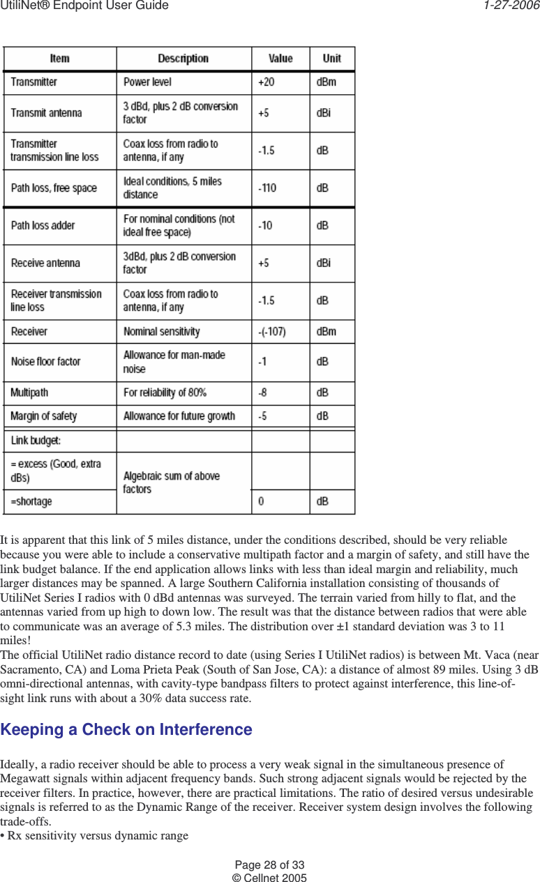
Landis Gyr Technology ER1S4 FOCUS UTILINET ENDPOINT User Manual 05 0393 Cover
Landis+Gyr Technology, Inc. FOCUS UTILINET ENDPOINT 05 0393 Cover
UserManual.wiki
>
Landis Gyr Technology
>
ER1S4 User Manual
USERS MANUAL
Navigation menu
Upload a User Manual
Namespaces
Wiki Guide
HTML
PDF
Info
Views
User Manual
Discussion / Help
Navigation
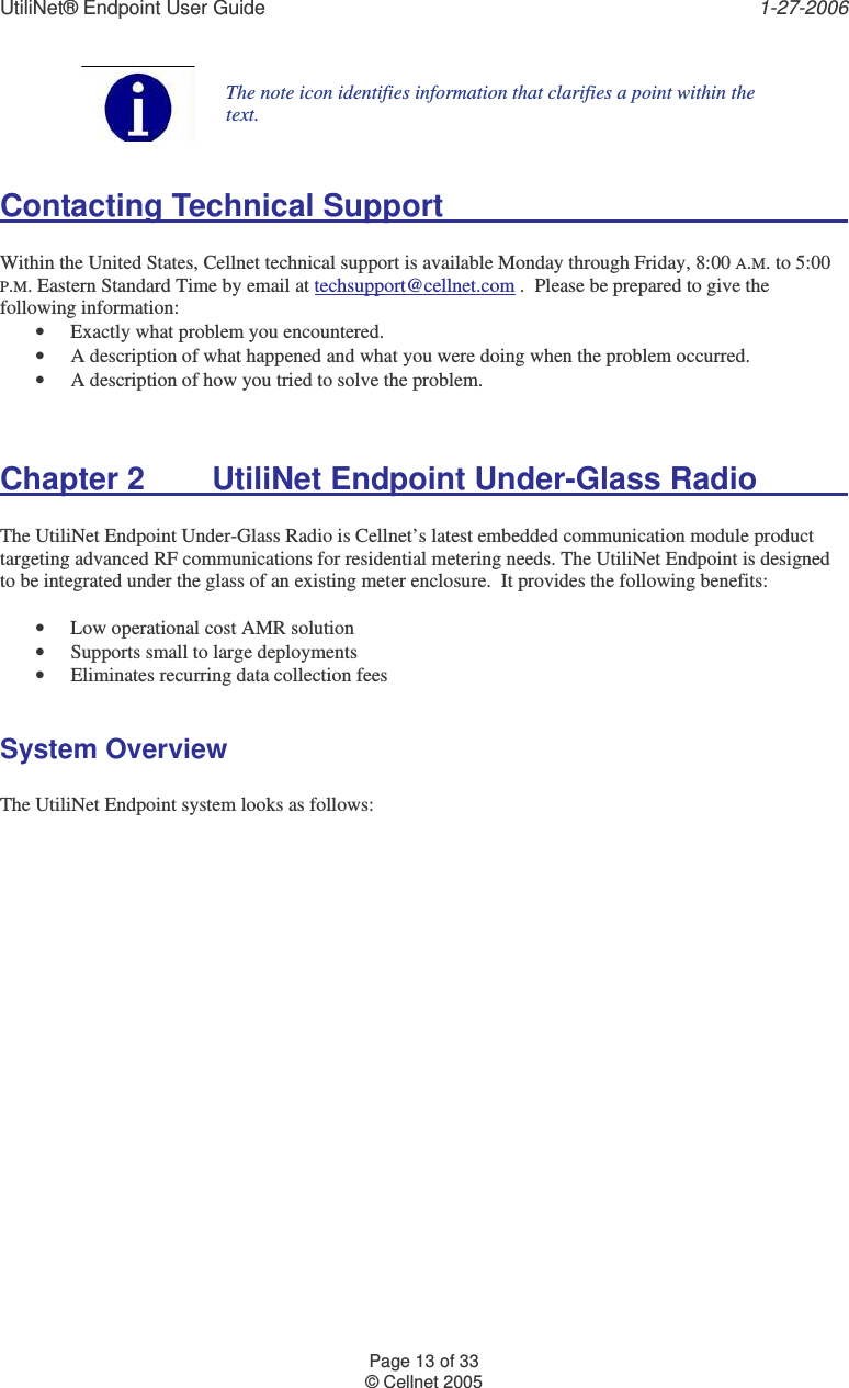
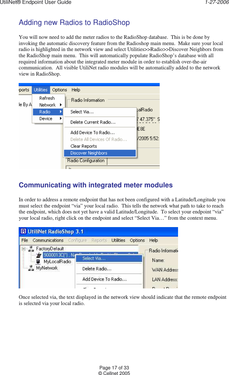
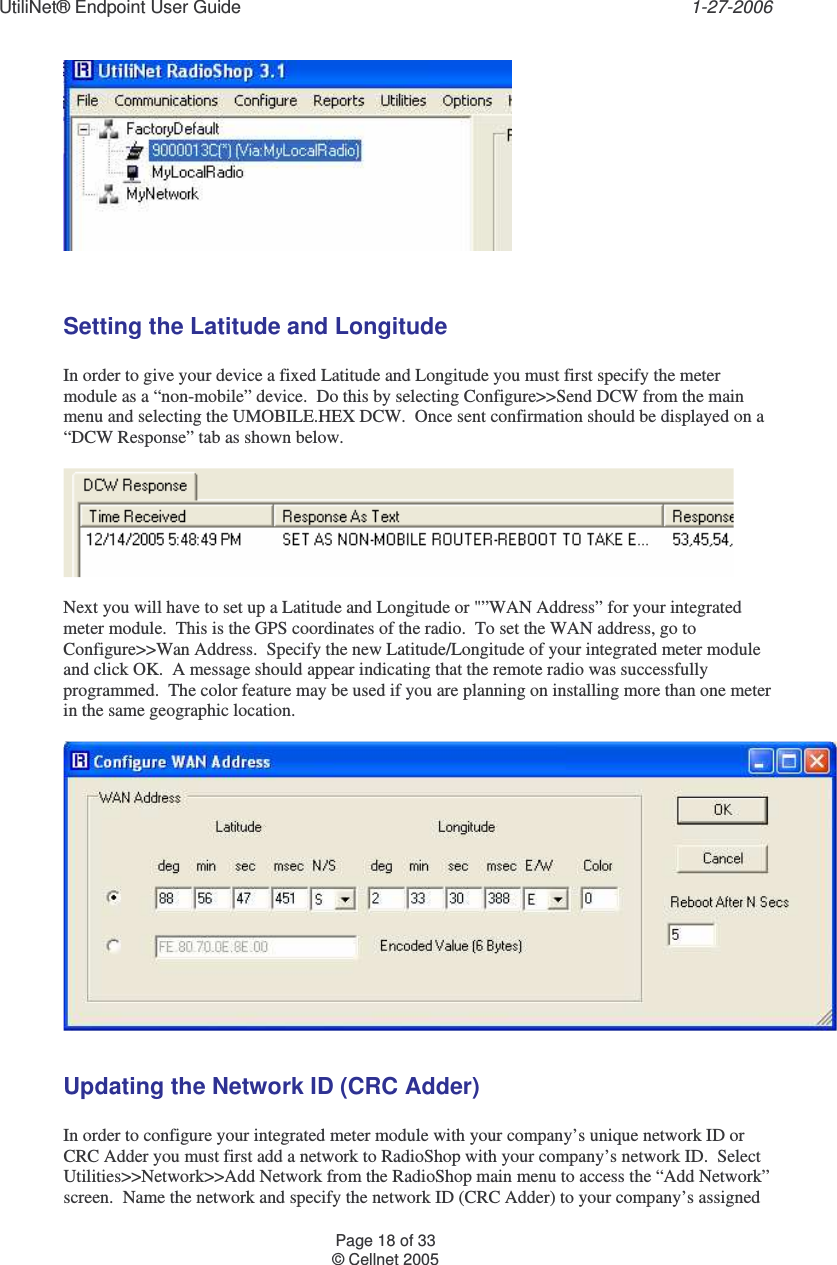
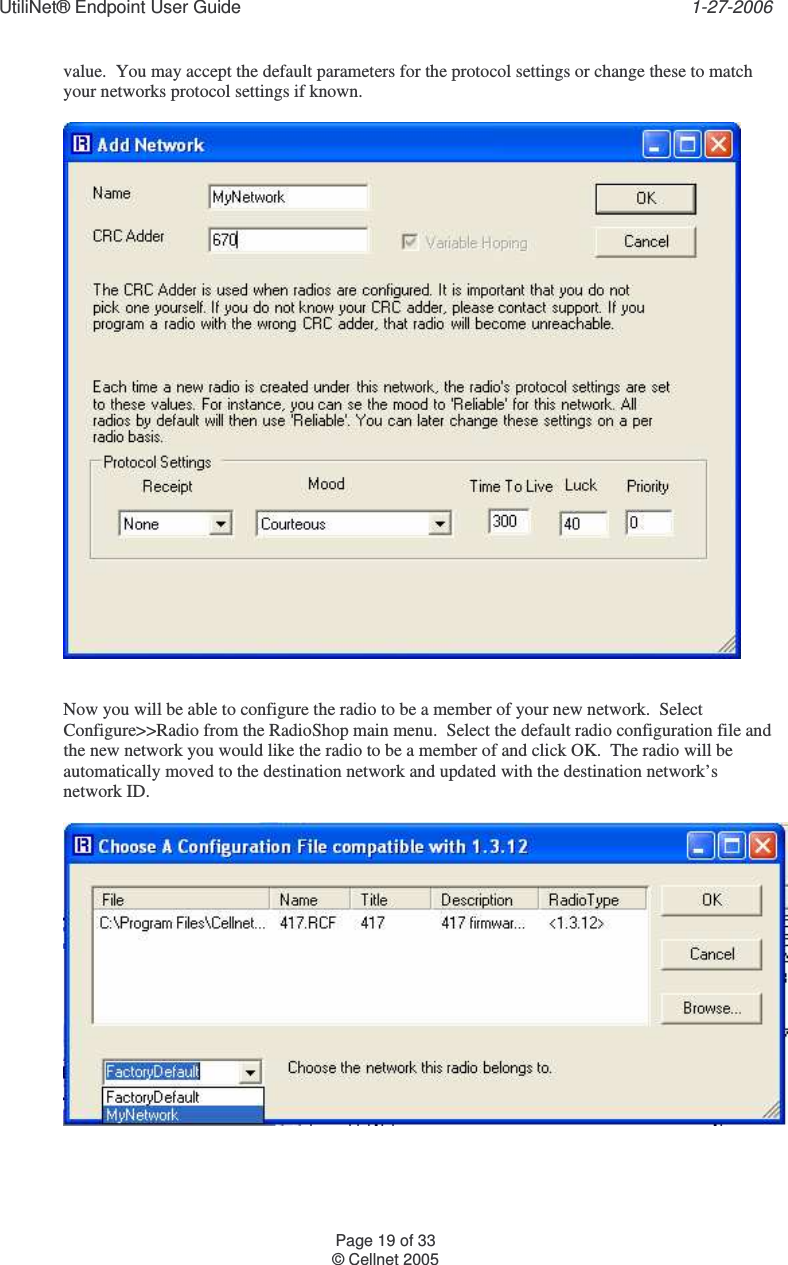
![UtiliNet® Endpoint User Guide 1-27-2006 Page 33 of 33 © Cellnet 2005 Bit 1: L3_MOOD_RELIABLE Bit 0: L3_MOOD_SCRAM (not supported) Multipoint Radios Multipoint radios are radios that may initiate data to multiple destination addresses. Packet Parameters The parameters in a packet that control the routing, processing, and limitations of its transmittal. The four packet parameters are mood, priority, luck, and time-to-live. Passive Multipoint Radios Passive multipoint radios are radios that may respond with data to multiple destination addresses, but only after being sent a request for data from that address. Persistent A mood packet parameter that specifies to use only battery backed radios for routing (source and destination need NOT be battery backed). Point Radios Point radios are radios that always transmit data to the same destination address. Priority A packet parameter that controls the processing of a packet. A higher priority packet is processed before a lower priority packet. A user packet can have a priority from 0 through 7 (0 being the lowest priority and 7 being the highest priority). It is not recommended that users regularly use high priorities. A few higher prioritylevels should always be reserved and unused for diagnostics. A non-user priority 8 is used for maintenance packets. Radios with version 413 of the firmware limit the priority of transparent packets to a maximum of 5. Protocol Protocol is the language used between the MTU and RTUs to communicate. Historically, each SCADA vendor produced his own protocol to prevent competition after the initial purchase decision was made. Quick A mood packet parameter that specifies to factor in both tickle and data success percentage when creating and ordering the scan lists. Reliable A mood packet parameter that specifies to limit “hop” distance to that specified by Short Hop Length [916BH] when creating scan lists. Radios farther than this configured distance will not be considered for passing off a packet with this mood setting. RTU Remote Terminal Unit, the RTU, is the slave or remote device that interfaces with field devices. The RTU is intelligent in that it contains a microprocessor but typically performs few tasks unless instructed to do so by the MTU. Scan List The list of radios that qualify to route a particular packet to. Status In the SCADA world, status refers to a digital input point to an RTU. The digital input point is in one of two possible states at any point in time. The point is a one or zero depending on the state of a physical contact that is directly connected to the RTU. For instance, a circuit breaker is either open or closed, a backwater gate is either up or down, or a lift pump is on or off. Time-To-Live A packet parameter than controls the maximum number of seconds that a packet can exist. The time-tolive counts down and if it reaches 0 before the packet reaches its destination, the packet is discarded. UART Universal Asynchronous Receiver Transmitter, UART, is an acronym given to an integrated circuit (IC) that relieves a microprocessor from some of the communications overhead involved in receiving and transmitting asynchronous, serial, byte oriented data. Typically UARTs are programmable for multiple baud rates, 7 or 8 data bits, 1 or 2 stop bits, and odd, even or no parity. WAN Address The 6-byte geographic address of the radio used for routing packets through the radio network. During the configuration process, a radio’s latitude, longitude, and color are converted into the 6-byte address that is actually used for routing.](https://usermanual.wiki/Landis-Gyr-Technology/ER1S4/User-Guide-631123-Page-34.png)