Landis Gyr Technology NG0R1S1 UTILINET SCADA SINGLE BOARD RADIO User Manual
Landis+Gyr Technology, Inc. UTILINET SCADA SINGLE BOARD RADIO
Users Manual

5015 B.U. Bowman Drive Buford, GA 30518 USA Voice: 770-831-8048 Fax: 770-831-8598
Certification Exhibit
FCC ID: R7PNG0R1S1
IC: 5294A-NG0R1S1
FCC Rule Part: 15.247
IC Radio Standards Specification: RSS-210
ACS Report Number: 08-300 - 15C
Manufacturer: Cellnet Technology Inc.
Model: Utilinet Modular SCADA/DA
Manual

UtiliNet SCADA
Single Board Radio
User Guide
Publication: 98-1546 Rev AA
Limitation on Warranties and Liability
Information in this document is subject to change without notice. This manual or any part of it thereof may not be
reproduced in any form unless permitted by contract or by written permission of Landis+Gyr.
In no event will Landis+Gyr be liable for any incidental, indirect, special, or consequential damages (including lost
profits) arising out of or relating to this publication or the information contained in it, even if Landis+Gyr has been
advised, knew, or should have known of the possibility of such damages.
© 2008 Landis+Gyr. All Rights Reserved.
Trademarks
UtiliNet®, and RadioShop® are registered trademarks of Landis+Gyr
ActiveSync®, Windows®,Windows 2000 Server®, Windows XP®, Windows Explorer®, and Windows Pocket PC® are
registered trademarks of Microsoft Corporation.
UtiliNet SCADA Single Board Radio User Guide
Publication: 98-1546 Rev AA
Landis+Gyr
30000 Mill Creek Ave., Suite 100
Alpharetta, GA 30022
Tel: (678) 258-1500
Fax: (678) 258-1550
Copyright© 2008 Landis+Gyr
All rights reserved.

UtiliNet SCADA Single Board Radio 98-1546 Rev AA 3
Table of Contents
Chapter 1: Product Overview . . . . . . . . . . . . . . . . . . . . . . . . . . . . . . . . . . . . . . . . . . . . . . . . . . . . . . . . . 5
Introduction . . . . . . . . . . . . . . . . . . . . . . . . . . . . . . . . . . . . . . . . . . . . . . . . . . . . . . . . . . . . . . . . . . . . . . . . . . . . . 5
Electrical Interface . . . . . . . . . . . . . . . . . . . . . . . . . . . . . . . . . . . . . . . . . . . . . . . . . . . . . . . . . . . . . . . . . . . . . . . 6
Pin Functions . . . . . . . . . . . . . . . . . . . . . . . . . . . . . . . . . . . . . . . . . . . . . . . . . . . . . . . . . . . . . . . . . . . . . 7
USB Programming Cable . . . . . . . . . . . . . . . . . . . . . . . . . . . . . . . . . . . . . . . . . . . . . . . . . . . . . . . . . . . 11
Antennas . . . . . . . . . . . . . . . . . . . . . . . . . . . . . . . . . . . . . . . . . . . . . . . . . . . . . . . . . . . . . . . . . . . . . . . . 13
External Antenna . . . . . . . . . . . . . . . . . . . . . . . . . . . . . . . . . . . . . . . . . . . . . . . . . . . . . . . . . . 13
On-Board Antenna . . . . . . . . . . . . . . . . . . . . . . . . . . . . . . . . . . . . . . . . . . . . . . . . . . . . . . . . . 13
Specifications . . . . . . . . . . . . . . . . . . . . . . . . . . . . . . . . . . . . . . . . . . . . . . . . . . . . . . . . . . . . . . . . . . . . . . . . . . 14
UtiliNet SBR On-Board Antenna Dimensions . . . . . . . . . . . . . . . . . . . . . . . . . . . . . . . . . . . . . . . . . . 17
UtiliNet SBR External Antenna Dimensions . . . . . . . . . . . . . . . . . . . . . . . . . . . . . . . . . . . . . . . . . . . .18
Chapter 2: Configuration & Testing . . . . . . . . . . . . . . . . . . . . . . . . . . . . . . . . . . . . . . . . . . . . . . . . . . . 19
Overview . . . . . . . . . . . . . . . . . . . . . . . . . . . . . . . . . . . . . . . . . . . . . . . . . . . . . . . . . . . . . . . . . . . . . . . . . . . . . . 19
Connecting to a Radio using RadioShop 4.0 . . . . . . . . . . . . . . . . . . . . . . . . . . . . . . . . . . . . . . . . . . . .19
Assign the Network ID (CRC) of the UtiliNet SBR . . . . . . . . . . . . . . . . . . . . . . . . . . . . . . . . . . . . . . 21
Assigning a New Network ID to a Radio . . . . . . . . . . . . . . . . . . . . . . . . . . . . . . . . . . . . . . . . . . . . . . 22
Adding New Radios to RadioShop . . . . . . . . . . . . . . . . . . . . . . . . . . . . . . . . . . . . . . . . . . . . . . . . . . . 23
Setting the Latitude & Longitude . . . . . . . . . . . . . . . . . . . . . . . . . . . . . . . . . . . . . . . . . . . . . . . . . . . . . 24
Troubleshooting . . . . . . . . . . . . . . . . . . . . . . . . . . . . . . . . . . . . . . . . . . . . . . . . . . . . . . . . . . . . . . . . . . . . . . . . 25
Chapter 3: Development Environment . . . . . . . . . . . . . . . . . . . . . . . . . . . . . . . . . . . . . . . . . . . . . . . . . 27
UtiliNet SCADA Single Board Radio Interface Board . . . . . . . . . . . . . . . . . . . . . . . . . . . . . . . . . . . . . . . . . . . 27
Transparent Port Connection . . . . . . . . . . . . . . . . . . . . . . . . . . . . . . . . . . . . . . . . . . . . . . . . . . . . . . . . 28
LAN Packet Port Connection . . . . . . . . . . . . . . . . . . . . . . . . . . . . . . . . . . . . . . . . . . . . . . . . . . . . . . . . 28
Onboard Regulator . . . . . . . . . . . . . . . . . . . . . . . . . . . . . . . . . . . . . . . . . . . . . . . . . . . . . . . . . . . . . . . . 28
Digital Input . . . . . . . . . . . . . . . . . . . . . . . . . . . . . . . . . . . . . . . . . . . . . . . . . . . . . . . . . . . . . . . . . . . . . 28
Analog Input . . . . . . . . . . . . . . . . . . . . . . . . . . . . . . . . . . . . . . . . . . . . . . . . . . . . . . . . . . . . . . . . . . . . 29
General Usage Instruction . . . . . . . . . . . . . . . . . . . . . . . . . . . . . . . . . . . . . . . . . . . . . . . . . . . . . . . . . . 29
UtiliNet SBR Logic . . . . . . . . . . . . . . . . . . . . . . . . . . . . . . . . . . . . . . . . . . . . . . . . . . . . . . . . . . . . . . . . . . . . . . 29
Digital I/O Functionality . . . . . . . . . . . . . . . . . . . . . . . . . . . . . . . . . . . . . . . . . . . . . . . . . . . . . . . . . . . 31
Analog Input Functionality . . . . . . . . . . . . . . . . . . . . . . . . . . . . . . . . . . . . . . . . . . . . . . . . . . . . . . . . . 31
Memory Location. . . . . . . . . . . . . . . . . . . . . . . . . . . . . . . . . . . . . . . . . . . . . . . . . . . . . . . . . . 33
Appendix A: External Antenna . . . . . . . . . . . . . . . . . . . . . . . . . . . . . . . . . . . . . . . . . . . . . . . . . . . . . . . 35
Manufacturer Contact Information . . . . . . . . . . . . . . . . . . . . . . . . . . . . . . . . . . . . . . . . . . . . . . . . . . . . . . . . . . 35
RF External Antenna Cable Specifications . . . . . . . . . . . . . . . . . . . . . . . . . . . . . . . . . . . . . . . . . . . . . . . . . . . . 35
External Antenna Specifications . . . . . . . . . . . . . . . . . . . . . . . . . . . . . . . . . . . . . . . . . . . . . . . . . . . . . . . . . . . . 36
Ground Plane Specifications . . . . . . . . . . . . . . . . . . . . . . . . . . . . . . . . . . . . . . . . . . . . . . . . . . . . . . . . 36
Antenna Radiation Pattern . . . . . . . . . . . . . . . . . . . . . . . . . . . . . . . . . . . . . . . . . . . . . . . . . . . . . . . . . . 37

Table of Contents Landis+Gyr
4 98-1546 Rev AA UtiliNet SCADA Single Board Radio
Appendix B: On-Board Antenna . . . . . . . . . . . . . . . . . . . . . . . . . . . . . . . . . . . . . . . . . . . . . . . . . . . . . . .39
On-Board Antenna Specifications . . . . . . . . . . . . . . . . . . . . . . . . . . . . . . . . . . . . . . . . . . . . . . . . . . . . . . . . . . .39
Appendix C: Regulatory Compliance . . . . . . . . . . . . . . . . . . . . . . . . . . . . . . . . . . . . . . . . . . . . . . . . . . .43
FCC - CFR Part 15.247 . . . . . . . . . . . . . . . . . . . . . . . . . . . . . . . . . . . . . . . . . . . . . . . . . . . . . . . . . . . . . . . . . . .43
Industry Canada . . . . . . . . . . . . . . . . . . . . . . . . . . . . . . . . . . . . . . . . . . . . . . . . . . . . . . . . . . . . . . . . . . . . . . . . .44
Appendix D: MMG Data Sheets . . . . . . . . . . . . . . . . . . . . . . . . . . . . . . . . . . . . . . . . . . . . . . . . . . . . . . . .45
Whip Antenna P/N 16-1000-0 . . . . . . . . . . . . . . . . . . . . . . . . . . . . . . . . . . . . . . . . . . . . . . . . . . . . . . . . . . . . . .45
MCX RF Connector P/N 21-1000-0 . . . . . . . . . . . . . . . . . . . . . . . . . . . . . . . . . . . . . . . . . . . . . . . . . . . . . . . . .46

1
UtiliNet SCADA Single Board Radio 98-1546 Rev AA 5
Product Overview
Introduction
The UtiliNet SCADA Single Board Radio (UtiliNet SBR) is for use by OEM vendors wanting to
incorporate the UtiliNet SBR capability within their SCADA/DA and metering products.
The UtiliNet SBR is a self-contained 100 mW Integrated WanGate Radio (IWR) which includes
voltage regulation, micro-processor, radio transmitter and receiver similar to the Series 3000 IWR.
This UtiliNet SBR, while a new design, is based upon existing UtiliNet IWR architecture. It is
similar in construction to a Commercial and Industrial (C&I) endpoint, but with an optional on-
board antenna. It has received Modular FCC approval when used with the approved cable and
antenna.
The UtiliNet SBR provides two digital I/O ports and two analog input ports, which can also be
configured as two general purpose I/O ports. One of the digital ports can also be configured as a
counter by sensing either the rising end or trailing edge of the pulse or both.
The UtiliNet SBR in addition to the IWR functionality supports several General Purpose Digital and
Analog interface connections. These interfaces are accessible via the UtiliNet Device Control Word
(DCW) programming language.
The UtiliNet SBR has 2 DCW interpreters (one large and one small) like other Landis+Gyr AMR
devices.
The design of the board allows integration with an OEM enclosure and interfacing with the
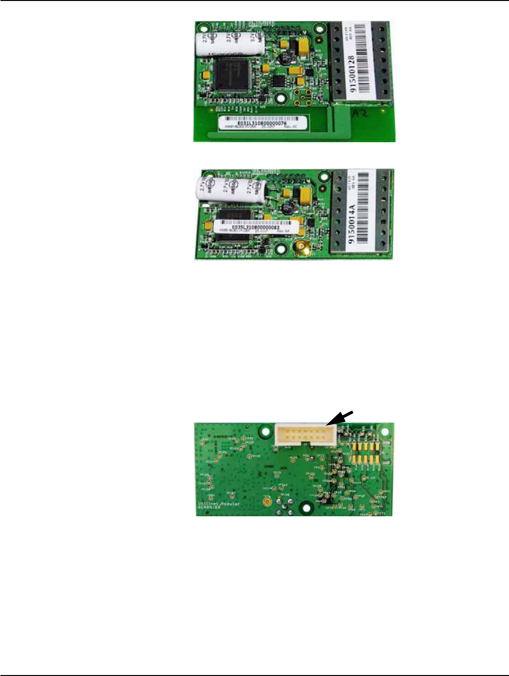
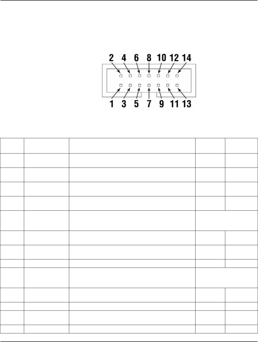
customer's equipment via a 14-pin interface connector.The UtiliNet SBR is available in two versions
(not interchangeable):
• On-Board Antenna, Part number 40-1119 (shown in Figure 1 - 1.)
• External Antenna (MCX connector), Part number 40- 1129 (shown in Figure 1 - 2.)
The On-Board antenna version is designed for customers seeking the lowest-cost solution. The on-
board F-antenna exhibits nominal performance. The external antenna version is designed for
customers who require enhanced performance (greater range).
Both UtiliNet SBR models have the same internal circuitry except for the type of antenna/
connector and board size.
Chapter 1 - Product Overview Landis+Gyr
6 98-1546 Rev AA UtiliNet SCADA Single Board Radio
Figure 1 - 1. UtiliNet SBR On-Board Antenna Version
Figure 1 - 2. UtiliNet SBR External Antenna Version
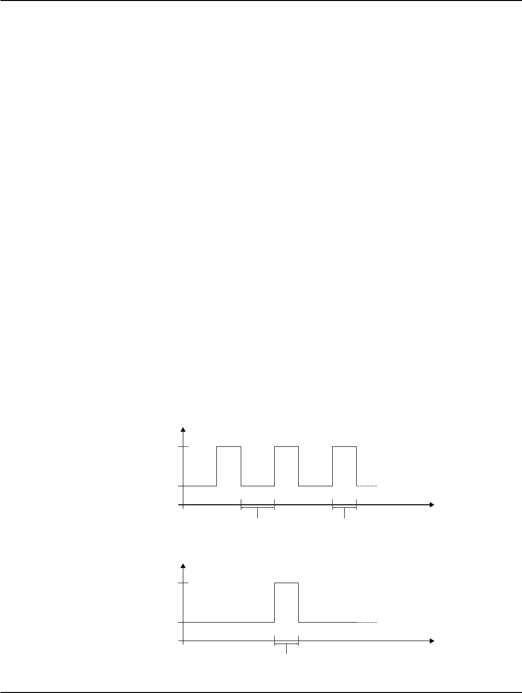
Electrical Interface
The electrical interface for power and control circuitry is provided via a connector located on the
bottom (non-component) side of the board. The connector is a 14-pin keyed shrouded header
connector as shown in Figure 1 - 3.
The UtiliNet SBR requires a nominal 5 VDC supply, with a total input range of 4 to 7 VDC. An
onboard regulator will drop the voltage to 3.4 VDC for the circuitry.
Figure 1 - 3. UtiliNet SBR (Reverse side)
The I/O connector provides interface connections as noted below:
• Power Supply
• LAN Packet Port (LPP)
• Transparent Port (TPP)
• Digital I/O signals
• Analog I/O signals
• Radio Enable/Disable control
• RF Power Control
I/O Connector
Landis+Gyr Chapter 1 - Product Overview
UtiliNet SCADA Single Board Radio 98-1546 Rev AA 7
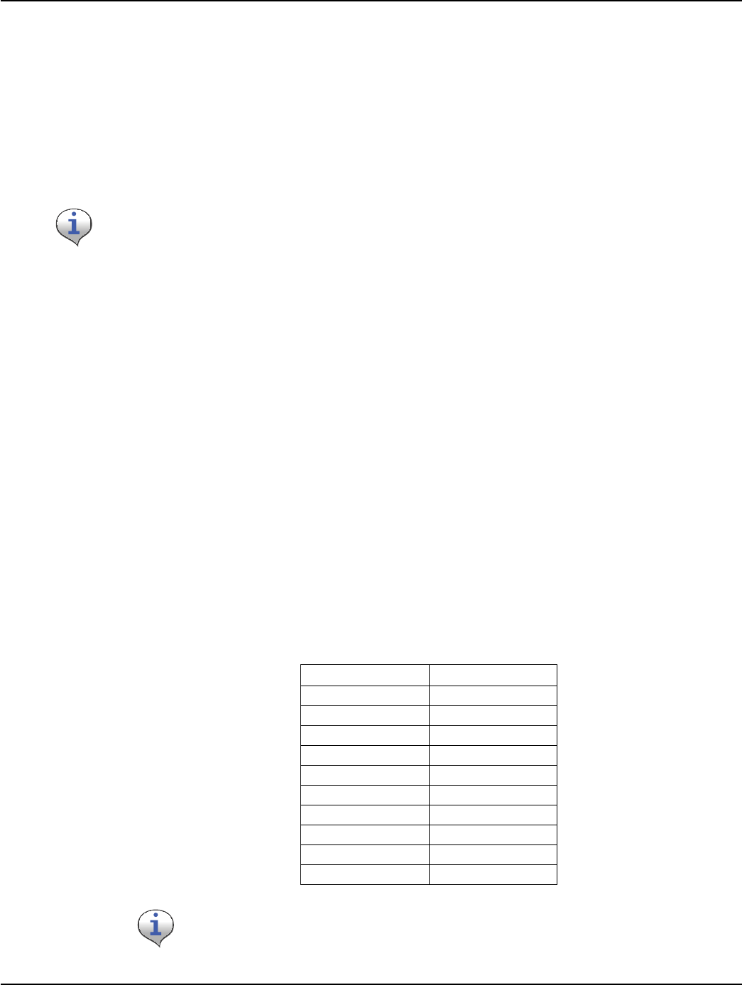
Pin Functions
Pin Outs for the connector as described below are designed to interface with the developer’s OEM
board. When pins are connected to non developer boards or when standard interfaces are required
without use of the USB cable (P/N 19-1220), appropriate design constraints (power and logic) must
be adhered to (See “UtiliNet SBR Logic” on page 29).
Figure 1 - 4. Pinout Diagram (as seen when viewing the board as shown in Figure 1 - 3.)
Table 1-1. I/O Connector Pin Functions and Acceptable Voltage Levels
Pin
Number Name Function Logic Level
Low (VDC)
Logic Level
High (VDC)
1 VIN Main supply for the board. 0 4.0 ~ 7.0
Nominal = 5
2 LPP TX This pin is an output from the device for connecting to
Radioshop via the LAN Packet Port (LPP) interface. 0 ~ 0.5 2.8 ~ 3.4
3 LPP RX This pin is an input to the device for connecting to
Radioshop via the LAN Packet Port (LPP) interface. 0 ~ 0.6 2.6 ~ 3.4
4 DIGITAL_IO1 A general purpose Digital Input / Output Pin. The
application-specific DCW can utilize this pin as desired. 0 ~ 0.6 2.6 ~ 3.4
5ANALOG_IN1
An input to the device’s A/D converter. The application-
specific DCW can read the voltage on this pin. Note: This
pin may be configured as a Digital I/O, if desired.
0 ~ 2.5
6 and 7 GND Common ground for both power and communications.
These two pins are tied together on the device. 00
8 LOW_RF_POWER Digital input used to select Low-Power Mode, an RF
output power reduction of 6[dB]. 0 ~ 0.6 2.6 ~ 3.4
9 PWR_DN Digital input used to completely shut down the device. 0 ~ 0.5 2.8 ~ 7
10 ANALOG_IN2
An input to the device’s A/D converter. The application-
specific DCW can read the voltage on this pin. Note: This
pin may be configured as a Digital I/O, if desired.
0 ~ 2.5
11 DIGITAL_IO2 A general purpose Digital Input / Output Pin. The
application-specific DCW can utilize this pin as desired. 0 ~ 0.6 2.6 ~ 3.4
12 TPP RX This pin is an input to the Transparent Port (TPP) device. 0 ~ 0.6 2.6 ~ 3.4
13 TPP TX This pin is an output from the Transparent Port (TPP)
device. 0 ~ 0.5 2.8 ~ 3.4
14 NC Not connected. N/A N/A
Chapter 1 - Product Overview Landis+Gyr
8 98-1546 Rev AA UtiliNet SCADA Single Board Radio
Pin 1 (VIN)
This pin must be supplied with DC voltage between 4.0 and 7.0 VDC with 5.0 VDC considered
nominal.
The input voltage of 5.0 VDC is linearly regulated on the board to 3.4 VDC. While the linear
regulation can remove some noise, its PSRR (Power Supply Rejection Ratio) varies with frequency.
If the power source is particularly noisy, filtering may be required. Landis+Gyr engineering can
assist in defining radio tests to determine if power supply noise is affecting radio performance.
The input voltage must be maintained between 4.0 VDC and 7.0 VDC during operation. The on-
board electronics include fast-acting reset circuitry. If the voltage drops below 4.0 VDC, even
transiently, the system will reboot once the voltage returns to normal range. If the voltage rises above
7.0 VDC, even transiently, the voltage-sensitive components could be damaged.
Upon power up, the on board processor and voltage regulator requires the supply voltage to have a
minimum of 0.05 V/msec slew rate - which implies rising from 0 to 3.4 VDC in 68 msec max.
During normal receive mode, current consumption is 25 mA.
During the first 30 minutes and after an extended outage or initial power on, the on-board super-
capacitor will be charging to prepare for outage notification (an RF function of the UtiliNet system).
During this time, the total input current to the device will increase to 55 mA.
During RF transmission at 100 mW, the UtiliNet SBR current consumption is 200 mA maximum.
The UtiliNet SBR uses a frequency hopping sequence transmission and, while typically rare,
transmissions can be as long as 400 mS in duration, and can theoretically sustained at a 45% duty
cycle.
The worst-case consumption profile, for a UtiliNet SBR that has just booted-up, charging its super-
capacitor, and transmitting packets at the max possible rate would be approximately 255 mA.
Typical current consumption is approximately 175 mA, drawn occasionally, for about 250 msec in
duration, and 25 mA when not transmitting.
Figure 1 - 5. Worst-Case Current Consumption Profile
Figure 1 - 6. Typical Current Consumption Profile
Time [mS]
55
255
~ 400[mS]~ 500[mS]
Iin [mA]
Time [mS]
25
175
~ 250[mS]
Occasional
Packets
Iin [mA]
Landis+Gyr Chapter 1 - Product Overview
UtiliNet SCADA Single Board Radio 98-1546 Rev AA 9
Pin 2 (LPP TX) and Pin 3 (LPP RX)
These pins are used to interface with the device's LAN Packet Port. These pins are driven at TTL
levels from 3.3 to 3.4 VDC.
Baud rates on this port default to 9600 bps, but using RadioShop are configurable up to 38,400 bps.
To reduce chances of electrical damage, a 10Kohm series resistor is placed in-series with the pin
which limits the drive current capability of this pin.
Stray physical capacitance on this circuit should be kept below 250[pF].
Pin 4 (DIGITAL_IO1) and Pin 11 (DIGITAL_IO2)
These pins are general purpose digital I/O lines and are driven at TTL levels from 3.3 to 3.4 VDC.
If not used, they should not be left unconnected and should be brought low connecting the pin to a
common ground.
If used, these pins must be driven to a valid logic high or low and not left at intermediate voltages as
this will result in indeterminate logic values and may damage the device.
Pin 5 (ANALOG_IN1) and Pin 10 (ANALOG_IN2)
These pins are analog inputs to the device. Voltages must be scaled to the 0 to 2.50 VDC range. The
UtiliNet SBR returns the DC voltage as HEX values in the memory locations as described in
“Analog Input Functionality” on page 31.
The value returned is shown in the table below.
The DCW that reads the memory location returns the HEX value, in the range of 0-03FF, from which
the user must convert to decimal and then using the formula can obtain the voltage value.
These pins are NOT directly connected to an RS-232 interface on a computer, and where such a
connection is necessary, the developer must purchase a TTL to RS-232 3.3 VDC converter which
is powered externally and NOT via the pins or the RS-232 connection on the computer.
Table 1-2. Voltage Conversion
Voltage = (Decimal value/1023) * 2.5
HEX Read Actual Voltage
0000 0
0006 0.01
006B 0.25
0119 0.68
0253 1.44
0382 2.19
039F 2.26
03C7 2.36
03F1 2.46
03FD 2.49
The Analog I/O pins may be configured as Digital I/O pins or as General Purpose I/O
pins, if desired.

Chapter 1 - Product Overview Landis+Gyr
10 98-1546 Rev AA UtiliNet SCADA Single Board Radio
Pins 6 and 7 (GND)
These pins are the ground connection for both power and communications. These two pins are tied
together on the device.
Pin 8 (LOW_RF_POWER)
The purpose for this pin is to reduce the RF output power level to assure operation during
development and OEM manufacturing process. A logic high on this pin leaves the device in its
normal mode of operation with full rated RF transmitter power. A logic low reduces the RF power
level to approximately 25 mW for use where high power is not required or maybe harmful. When the
USB cable is used to power the board, the pin is brought low. This pin is a digital input, driven at
TTL levels from 3.3 to 3.4 VDC.
This pin must be driven to a valid logic high or low as intermediate voltages will result in
indeterminate logic values and may damage the device.
Pin 9 (PWR_DN)
This pin is used to enable or disable the device. This pin is a digital input and must be driven to a
valid logic high or low, as intermediate voltages will result in indeterminate logic values and may
damage the device.
A logic high enables the linear regulator, thus powering the device.
A logic low disables the linear regulator and turns off the device.
Prior to turning off the device, all interface signals must be driven low and logic voltage removed.
This includes all Serial UART lines, digital and analog I/O lines.
When the device is turned off with this pin, total current consumption will be less than 2 µA.
Pin 12 (TPP RX) and Pin 13 (TPP TX)
These pins are used to interface with the device's Transparent Port. These pins are driven at TTL
levels from 3.3 to 3.4 VDC.
Baud rates on this port default to 9600 bps, but using RadioShop are configurable up to 38,400 bps.
To reduce chances of electrical damage, a 10Kohm series resistor is placed in-series with the pin
which limits the drive current capability of this pin.
Stray physical capacitance on this circuit should be kept below 250[pF].
When the board is not in use, voltage should not be applied to any interface as this may damage
the device as destructive latch-up can result.
These pins are NOT direct connect to an RS-232 interface on a computer and where such a
connection is necessary, the developer must purchase a TTL to RS-232 3.3 VDC converter which
is powered external and NOT via the pins or the RS-232 connection on the computer.
Landis+Gyr Chapter 1 - Product Overview
UtiliNet SCADA Single Board Radio 98-1546 Rev AA 11
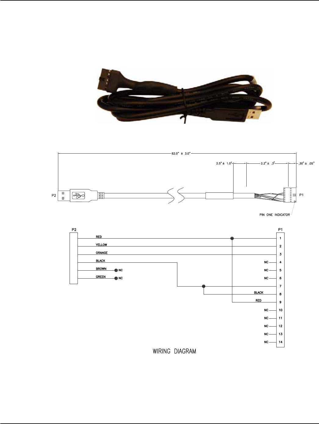
USB Programming Cable
A USB Serial Interface programming cable (P/N 19-1220, shown in Figure 1 - 7) is available for
developers to access the device via the I/O connector using RadioShop 4.0 or their own application.
The cable provides power (5 VDC) and a single emulated COM Port connection. The USB cable
allows the OEM vendor to configure, load DCWs, and program the UtiliNet SBR.
Figure 1 - 7. USB Serial Interface programming cable
The cable uses the pins as shown in Figure 1 - 8.
Figure 1 - 8. USB Serial Interface programming cable wiring diagram
The cable converts USB to Serial (TTL level) for connecting the TTL interfaces on the board to
serial interfaces (COM Ports) via the USB interface. The cable is designed to allow for a fast, simple
way to connect the board to the RS-232 COM Port on the PC, allowing the developer to access the
board using RadioShop.
Chapter 1 - Product Overview Landis+Gyr
12 98-1546 Rev AA UtiliNet SCADA Single Board Radio
The entire USB protocol is handled by the USB Serial Interface cable when connected to the pc, thus
no USB specific firmware programming is required.
Because most computer USB ports can only source 100 mA of current, the USB cable sets the device
for RF Low Power Mode by grounding pin 8 of the I/O connector. This mode sets the output power
level to approximately 25 mW. The USB is 2.0 Full Speed compatible thus providing for COM Port
data rates between 300 to 38,200 BPS as required by the radio LPP port.
USB Cable Installation
Connect the device to a spare USB port on your PC. The Microsoft composite device driver is
automatically loaded silently in the background. Once the composite driver has been installed
Windows Found New Hardware Wizard will launch.
The installation process may continue by installing the USB Serial Converter driver for a second
port of the USB Cable. The procedure for installing the second port is identical to that for installing
the first port from the first screen of the Found New Hardware Wizard.
Table 1-3. USB Cable I/O Operating Parameters
Parameter Description Min Type Max Unit Conditions
VCC Output Power
Voltage 4.25 5.0 5.25 VDC Dependant on the USB port that
the TTL-232R-3V3 is connected to
I/O Output Power
Current N/A N/A 100 mA N/A
TOperating
Temperature Range -40 - +85 °C N/A
Prior to connecting the USB cable the first time, make sure the PC is connected to the Internet.
Landis+Gyr Chapter 1 - Product Overview
UtiliNet SCADA Single Board Radio 98-1546 Rev AA 13
Antennas
As with any RF device, antenna-related decisions are critical and must be made early. The RF range
of the final product will depend greatly on the choice of antenna and its placement. This module is
available in two versions, selected at the time of order. The On-Board Antenna version is built and
tuned to utilize an on-board F-antenna. The External Antenna version includes a 50-ohm MCX
connector for RF co-ax connection to an external antenna.
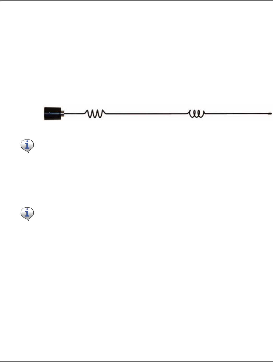
External Antenna
An external antenna is connected to the board via an MCX Female coaxial RF connector.
The External Antenna used to qualify the board is a 5 dB whip (shown in Figure 1 - 9.), made by
MMG. The MMG antenna part number is 16-1000-0. MMG contact information is on page 35.
Figure 1 - 9. Whip Antenna with N-type Male Reverse-Polarity Connector
On-Board Antenna
The On-Board antenna design is an F-antenna. This design was chosen because its performance is
more broad-band relative to a slot antenna, and its pattern is somewhat Omni-directional. This
version of the product does not allow an external antenna in conjunction to the on-board antenna.
See “External Antenna Specifications” on page 36 for Antenna technical specifications.
See “On-Board Antenna Specifications” on page 39 for Antenna technical specifications.

Chapter 1 - Product Overview Landis+Gyr
14 98-1546 Rev AA UtiliNet SCADA Single Board Radio
Specifications
Table 1-4. Physical Specifications
Category Specification Value(s) or Range(s)
Electrical
Supply Voltage 5.0 typical (4.0 min, 7.0 max)
Current, Transmit Mode 200 mA maximum
Current, Receive Mode 25 mA typical, 40 mA maximum
Networking
Number of Channels 240
Channel Spacing 100 KHz
Modulation Type Direct 2-FSK
RF Baud Rate 9600
FCC Operation Certification Part 15.247 Spread Spectrum
Spreading Technique Frequency Hopping
Hopping Technique Pseudo Random Asynchronous
Hopping Patterns 65,536 (Unique per network)
Network Address Latitude / Longitude Coordinates
Turn-Around Time 100[uS] max
Data/Programming
Programming Language Device Control Word (DCW)
Transparent Port Serial Interface, DCW adjustable per specs below
Serial Interface TTL (adj. Reference)
Data Rate 300, 600, 1200, 4800, 9600, 19200, or 38400
Parity Odd, Even, or None
Data bits 7 or 8
Stop bits 1 or 2
Duplex Full
Protocol Any asynchronous byte-oriented protocol
Environmental
Operating Temperature -40°C to +85°C
Storage Temperature -40°C to +85°C
Humidity 85C, 95% RH
Mechanical Size On-Board Antenna 3.5” x 2.25” x 1.0”
External Antenna 3.5” x 1.75” x 1.0”

Landis+Gyr Chapter 1 - Product Overview
UtiliNet SCADA Single Board Radio 98-1546 Rev AA 15
Table 1-5. RF Specifications
Category Specification Value(s) or Range(s)
Frequency (MHz) Condition Minimum Typical Maximum
Transmitter
RF Output 902.1~927.9
Max Power Mode
Referenced to Antenna
connector, CW
+18.0 dBm +20.0 dBm N/A
Low Power Mode
Reference to Antenna
connector, CW
+12.0 dBm +14.0 dBm N/A
Frequency
Range f0N/A 902.1 MHz N/A 927.9 MHz
Out-of-band
Radiated
Spurious
10~10000
2*f0
3*f0~10*f0
1KHz RBW, TX on,
CW, +20 dBm N/A N/A
-20
-45
-70
Deviation N/A N/A -5.5 kHz N/A +5.5 kHz
Modulation
Bandwidth N/A N/A N/A N/A 25 kHz
Output
Impedance N/A N/A N/A 50 :N/A
Frequency
Stability f0-40°C ~ +85°C -3 ppm N/A +3 ppm
Conducted
Spurious
Emissions
902.1~927.9 2*f0N/A N/A -20 dBc
902.1~927.9 3*f0~10*f0N/A N/A -70 dBc
Total Device
Current N/A
Max Power Mode Pout
= +20.0 dBm, TX On,
CW
N/A 150 mA 200 mA
Low Power Mode Pout
= +14 dBm, TX On,
CW
N/A 80 mA 100 mA

Chapter 1 - Product Overview Landis+Gyr
16 98-1546 Rev AA UtiliNet SCADA Single Board Radio
Receiver
Sensitivity 902.1~927.9 BER 5E-5 N/A -108 dBm -105 dBm
Dynamic
Range (Input
Signal Level)
N/A 1X10⁻⁶ BER -108 dBm N/A 0 dBm
Packet Error
Rate N/A N/A N/A 1x10⁻²
(1X10⁻⁶ BER) N/A
IF Selectivity N/A @ 25 kHz 39 dB N/A N/A
Frequency
Stability f0-40°C ~ +85°C -3 ppm N/A +3 ppm
Total Device
Current N/A RX On N/A N/A 40 mA
IIP3 915 N/A -25 dBm N/A N/A
Adjacent
Channel
Rejection
N/A N/A 35 dB N/A N/A
Worst case
Image
Rejection
N/A N/A N/A 20 dB N/A
Table 1-5. RF Specifications
Category Specification Value(s) or Range(s)
Frequency (MHz) Condition Minimum Typical Maximum
Landis+Gyr Chapter 1 - Product Overview
UtiliNet SCADA Single Board Radio 98-1546 Rev AA 17
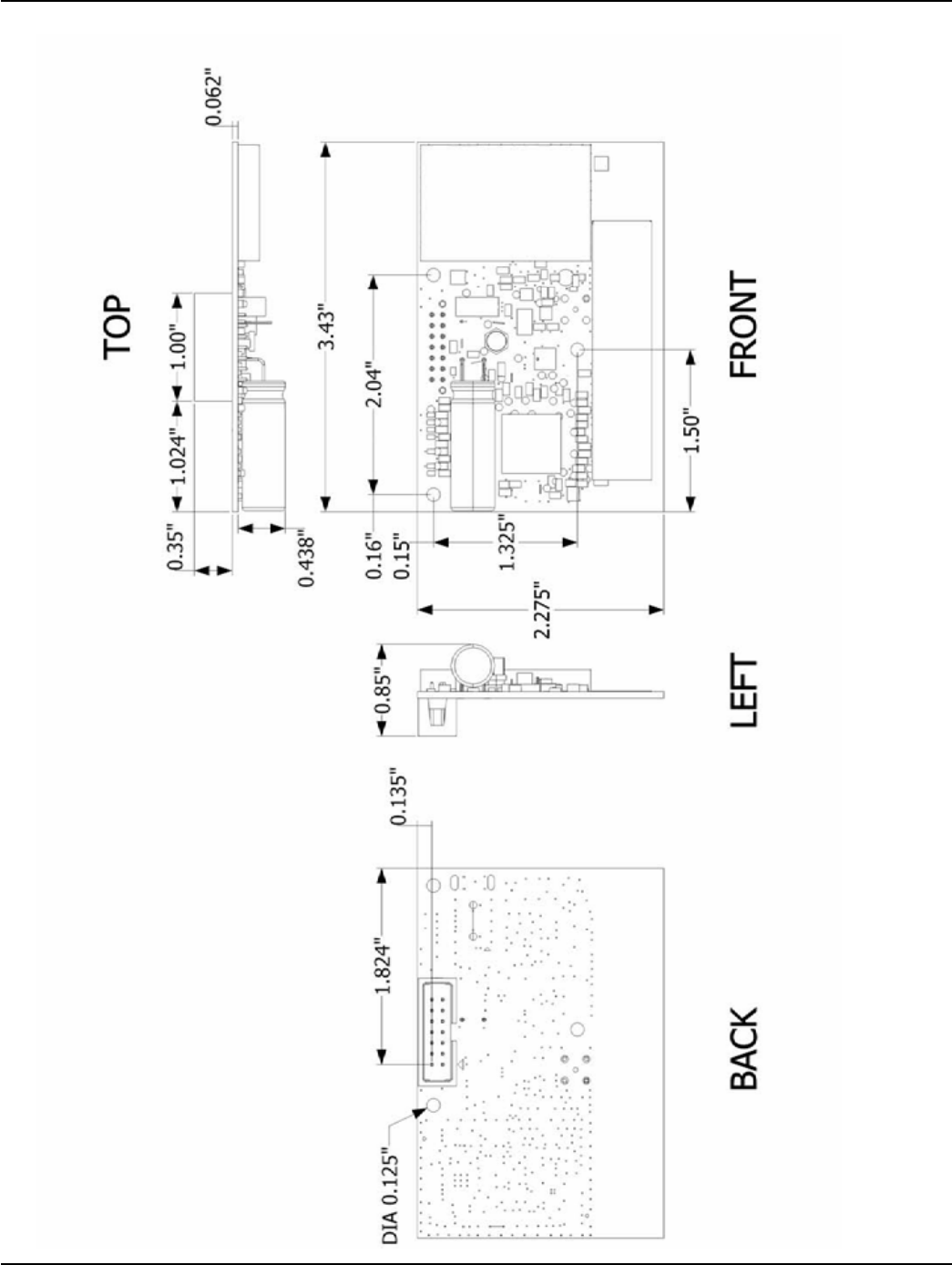
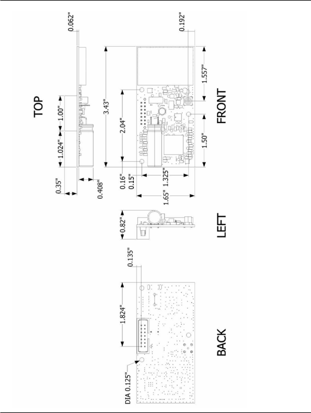
UtiliNet SBR On-Board Antenna Dimensions
Figure 1 - 10. UtiliNet SBR On-Board Antenna Dimensions
Chapter 1 - Product Overview Landis+Gyr
18 98-1546 Rev AA UtiliNet SCADA Single Board Radio
UtiliNet SBR External Antenna Dimensions
Figure 1 - 11. UtiliNet SBR External Antenna Dimensions
2
UtiliNet SCADA Single Board Radio 98-1546 Rev AA 19
Configuration & Testing
Overview
The UtiliNet SCADA Single Board Radio is configured using the RadioShop 4.0 (or later) program
only. Setup is similar to setting up and configuring any UtiliNet Radio.
Refer to the RadioShop 4.0 Getting Started Guide for further details about configuring the UtiliNet
SBR.
Connecting to a Radio using RadioShop 4.0
Connect the LAN Packet Protocol port of your IWR to your computer's serial port using a serial
cable. Once the radio is powered up, you can launch RadioShop 4.0 on your computer. RadioShop
will now connect to your local UtiliNet SBR card.
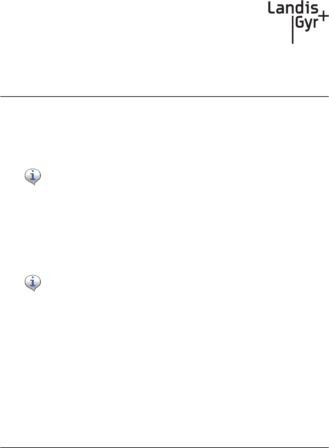
1. From RadioShop home select the Head-End Mgmt tab.
2. Click Discover>Force Scan and Discover Entry Ports.
RadioShop version number is subject to change. Refer to the latest version of the RadioShop
Programming Guide for additional detail.
When the Select COM Ports for Discovery window opens, select the COM port on your
computer that is connected to the radio, and then click OK.
Chapter 2 - Configuration & Testing Landis+Gyr
20 98-1546 Rev AA UtiliNet SCADA Single Board Radio
Figure 2 - 1. Connecting to Head-End Radio
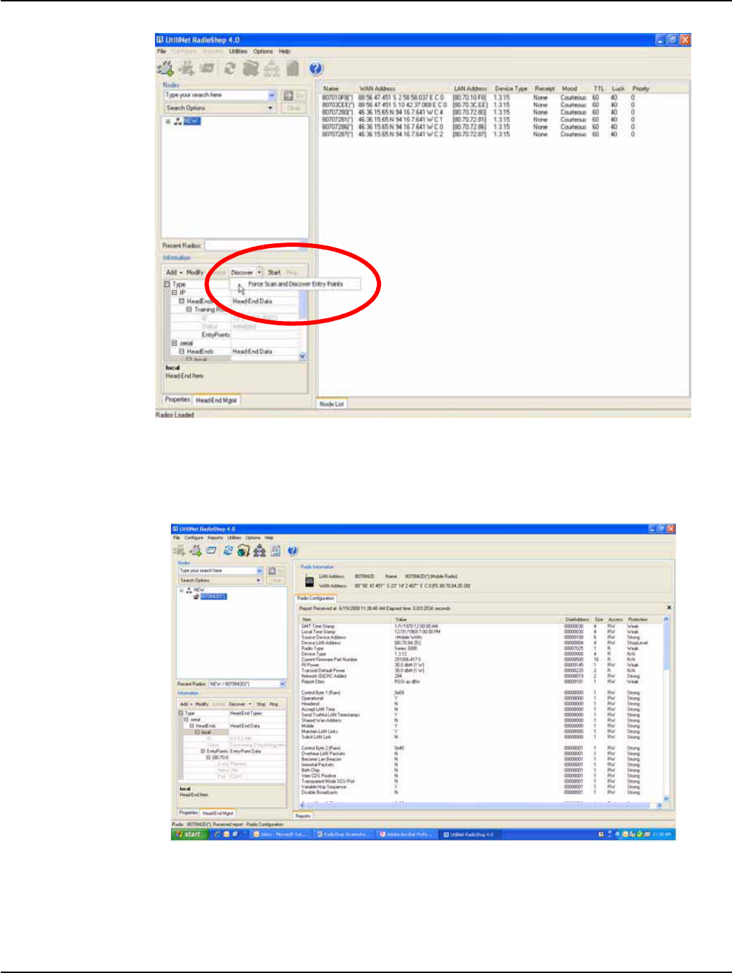
Once connected, the local radio's LAN address will appear on the list at the top left-hand side of the
screen, and a radio configuration report will be displayed in the main window (See Figure 2 - 2.).
This radio can now be used to communicate with the UtiliNet SBR and configure it as needed.
Figure 2 - 2. Radio Configuration Report for Head-End Radio
Landis+Gyr Chapter 2 - Configuration & Testing
UtiliNet SCADA Single Board Radio 98-1546 Rev AA 21
Assign the Network ID (CRC) of the UtiliNet SBR
All UtiliNet SBRs ship with a default network ID, or CRC, of 670. In order to communicate with
other radios in a customer's network, the UtiliNet SBR will have to be re-configured to match the
customer's unique network ID.
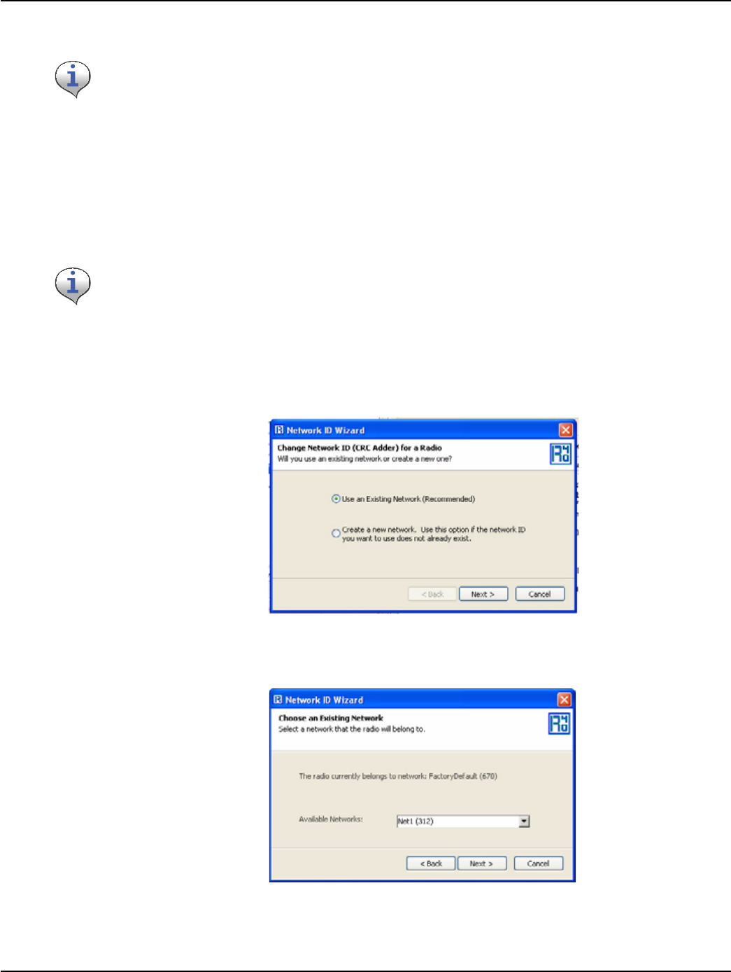
1. From RadioShop home, select Configure>Change Network ID (CRC). The Network ID
Wizard dialog box will open, as shown in Figure 2 - 3
2. Select Use an Existing Network, and click Next to continue.
Figure 2 - 3. Network ID Wizard
The Choose an Existing Network dialog is displayed
Figure 2 - 4. Choose an Existing Network
3. Choose a Network ID from the Available Networks drop-down list, and click Next to continue.
All RF Mesh radios ship with a default network ID, or CRC, of 670. In order to communicate with
the UtiliNet SBR, your local radio will have to be re-configured to match the network ID (670) of the
UtiliNet SBR. After re-configuring the UtiliNet SBR to match the customer’s unique network ID, the
local radio will need to be reset to it’s original network ID. See “Assign the Network ID (CRC) of the
UtiliNet SBR” on page 21 or see “Assigning a New Network ID to a Radio” on page 22., for steps
to re-configure the local radio.
Network ID or CRC are usually assigned for each customer. Please call Customer Service at 888-
390-5733 if you require a Network ID or CRC.
Chapter 2 - Configuration & Testing Landis+Gyr
22 98-1546 Rev AA UtiliNet SCADA Single Board Radio
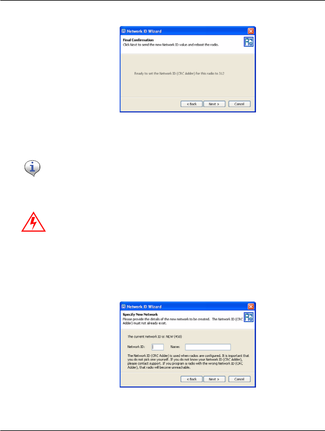
The Final Confirmation dialog is displayed
Figure 2 - 5. Final Confirmation dialog box
4. Click Next to change the Network ID for the radio.
A confirmation message verifies that the Network ID has been changed.
Assigning a New Network ID to a Radio
To assign a new Network ID to a radio, perform the following steps.
1. Select Configure > Network Id (CRC). The first dialog of the Network ID Wizard is displayed.
2. Select Create a New Network, and then click Next.
The Specify New Network dialog is displayed
Figure 2 - 6. Specify New Network
3. Specify the Network ID and Name of the new network you want to assign, and click Next to
continue.
Radio will reboot.
Important:
Assign a new Network ID only if the ID you want to use does not exist already.
Valid values range from 1 to 65535. If 0 is displayed at startup, call customer support.
Landis+Gyr Chapter 2 - Configuration & Testing
UtiliNet SCADA Single Board Radio 98-1546 Rev AA 23
The Final Confirmation dialog is displayed.
4. Click Next to create the Network ID for the radio. A confirmation message verifies that the new
Network ID has been assigned to the radio.
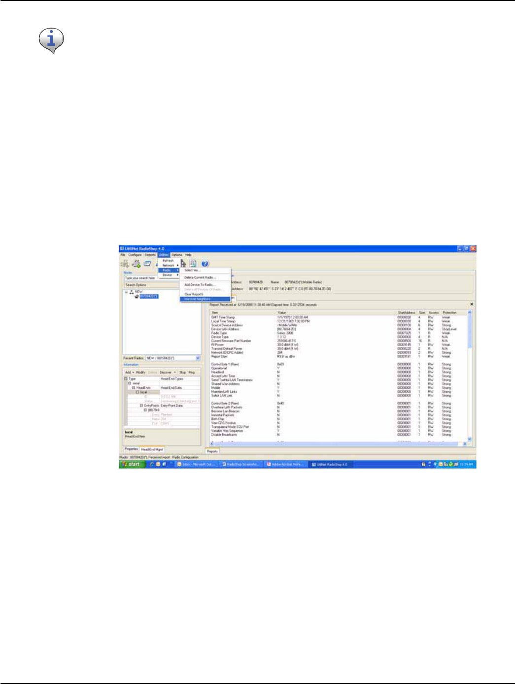
Adding New Radios to RadioShop
You can now add the UtiliNet SBR to the RadioShop database.
1. Make sure your local radio is highlighted on the Nodes Pane.
2. Click Generate WAN Nodes Report.
3. From RadioShop home click Utilities > Radio > Discover Neighbors. See Figure 2 - 7.
Figure 2 - 7. Discovering Neighbors
4. Once discovered, the UtiliNet SBR’s LAN Address will show up on the Nodes pane, as shown
in Figure 2 - 8.
Do not use spaces in the Name field.
Chapter 2 - Configuration & Testing Landis+Gyr
24 98-1546 Rev AA UtiliNet SCADA Single Board Radio
Figure 2 - 8. RMFM is added to Nodes Pane
5. Highlight the new UtiliNet SBR, Figure 2 - 8, and click Reports > Configuration > Radio to
verify that you can communicate with the UtiliNet SBR
6. On the report, you can verify the firmware version and current network ID.
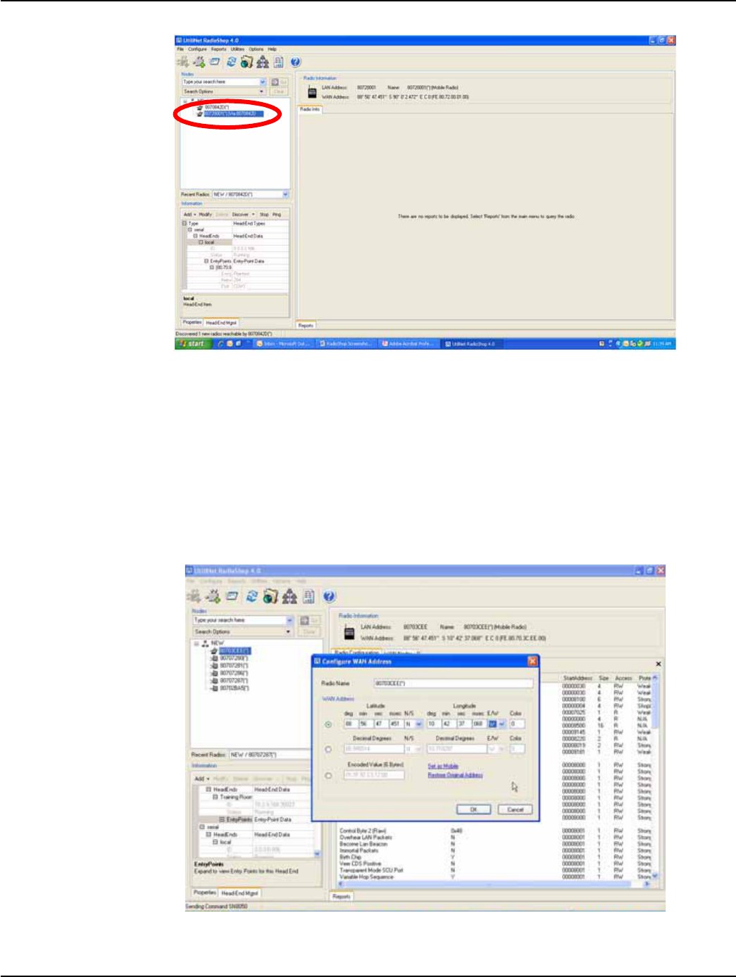
Setting the Latitude & Longitude
1. From RadioShop home click Configure > Wan Address.
2. The Configure WAN Address window, specify the new coordinates and click OK.
Figure 2 - 9. Configuring the WAN Address
A message will appear indicating that the radio was successfully programmed.

Landis+Gyr Chapter 2 - Configuration & Testing
UtiliNet SCADA Single Board Radio 98-1546 Rev AA 25
Troubleshooting
The UtiliNet SBR has been designed as a Field Replaceable Unit. As such, there are no serviceable
parts in the unit.
If you suspect parts within the UtiliNet SBR have failed:
1. Perform a visual inspection to determine if there is any visual indications of damage to the unit.
2. Verify that AC power is being supplied to the unit. If there is power then proceed to step 3.
3. Try to connect with a locally connected Series III IWR configured the same as the UtiliNet SBR.
If after 5 minutes, the locally connected Series III IWR does not acquire the UtiliNet SBR in its
neighbors list, the UtiliNet SBR should be replaced.
For additional assistance for this product, contact Technical Support toll-free at 1-888-390-5733 or
support@landisgyr.com.

Chapter 2 - Configuration & Testing Landis+Gyr
26 98-1546 Rev AA UtiliNet SCADA Single Board Radio
3
UtiliNet SCADA Single Board Radio 98-1546 Rev AA 27
Development Environment
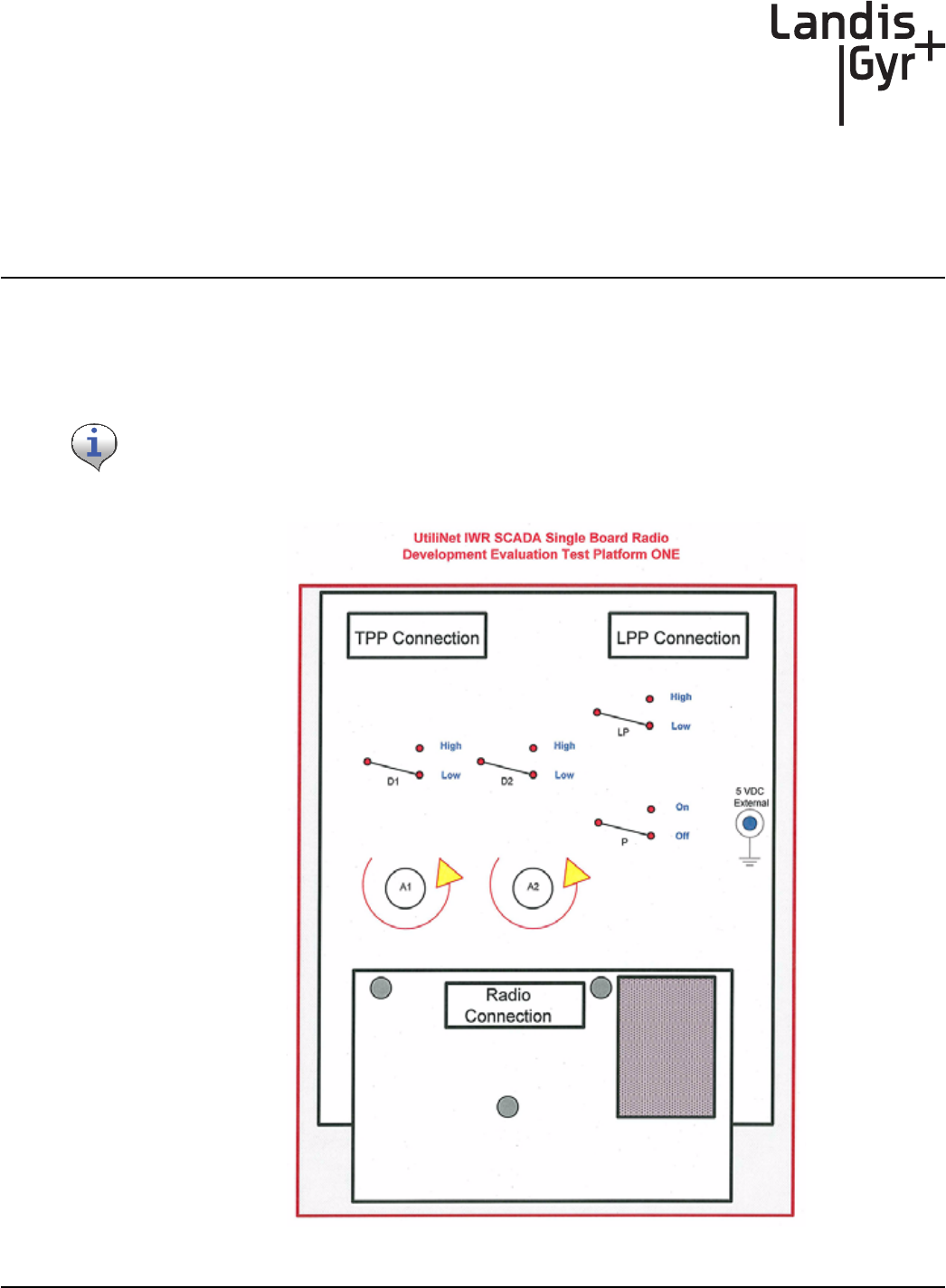
UtiliNet SCADA Single Board Radio Interface Board
This section provides instruction for the usage of the UtiliNet IWR Single Board Radio interface
board, a simple prototype board wired to interface a UtiliNet IWR Single Board Radio to a PC.
Figure 3 - 1. Board Component Layout with On-Board Antenna
The drawings provided in this section are for design reference purposes only. No interface board is
available for purchase from Landis+Gyr.
Chapter 3 - Development Environment Landis+Gyr
28 98-1546 Rev AA UtiliNet SCADA Single Board Radio
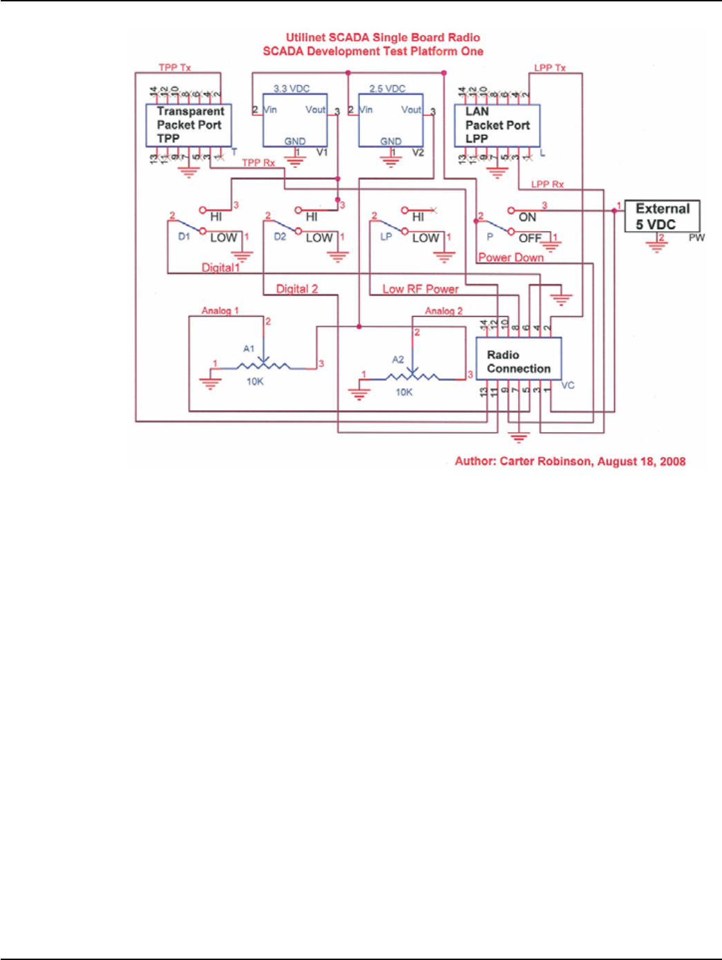
Figure 3 - 2. Board Component Schematic
Transparent Port Connection
This connector is used to establish connection to the UtiliNet SBR through the transparent port.
When communication through the transparent port is desired, connect the USB cable to this
connector.
LAN Packet Port Connection
This connector is used to establish connection to the UtiliNet SBR through the LAN packet port.
When communication through the LAN packet port (RadioShop) is desired, connect the USB cable
to this connector.
Onboard Regulator
The UtiliNet SBR interface board is equipped with an onboard 3.4 VDC regulator. This regulator
takes a 4 ~ 7 VDC input from a main power source and regulates it at 3.4 VDC for the device's
electronics.
Digital Input
Digital input to UtiliNet SBR can be tested by toggling the two switches on the test board that
correspond to DIGITAL_IO1 and DIGITAL_IO2. The switch will toggle between 0V and 3.3VDC.
Landis+Gyr Chapter 3 - Development Environment
UtiliNet SCADA Single Board Radio 98-1546 Rev AA 29
Analog Input
Analog input to the UtiliNet SBR can be tested by tuning the two potentiometers on the test board
that correspond to ANALOG_IN1 and ANALOG_IN2. The input voltage should lie between 0 VDC
and 2.5 VDC.
General Usage Instruction
Depending on the desired port to establish communication, connect a main cable to either the
transparent port connection or the LAN packet port connection.
Set the USB power input to an appropriate level (recommended: 5V). Toggle the switch controlling
the signal *PWR_DN to LOW position.
Connect the UtiliNet SBR to the test board through the board-to-board I/O connector.
Toggle the switch controlling the signal *PWR_DN to HIGH position to turn the UtiliNet SBR ON.
The switch controlling *LOW_RF_POWER may be toggled to set the transmit level of the UtiliNet
SBR under test: whether to transmit with limited or full power and power consumption.
UtiliNet SBR Logic
Developers desiring to use the UtiliNet SCADA Single Board Radio in their SCADA equipment to
monitor equipment should be aware of the logic of the setting when writing a DCW program. The
following describes the logic for reading and writing at Control Registers 1 and 2 located at memory
locations 7700h and 7700h in the radio using a DCW.
Control Register 1
D1-Input
Pin D1 at 7700h (Bits 0-3), if 7700h (Bit 0 = "0") Input then read Control at 7700h (Bits 2-3)
•If Control = "00" - General Purpose => Read state at 7700h (Bit 1) and report
This interface board does not have function to test the digital output of the UtiliNet SBR, with the
digital input switch tying the digital I/O pin on the UtiliNet SBR to either 0V or 3.3VDC. It is
recommended to NOT configure the digital I/O pin when the UtiliNet SBR is connected to the test
interface board.
With an on-board reference of 2.5 VDC, the highest analog input the UtiliNet SBR may sense is 2.5
VDC. Although the processor on the UtiliNet SBR may withstand 3.3 VDC analog input, it is
advised to not exceed 2.5 VDC.
To provide power to the UtiliNet SBR test Platform, the power input must be supplied externally
(as shown). Therefore the USB Cable when connected to the TPP or LPP connector does not
provide power for the test board.
When connecting the USB cable directly to the Utilinet SBR power is provided by the USB port on
the computer.

Chapter 3 - Development Environment Landis+Gyr
30 98-1546 Rev AA UtiliNet SCADA Single Board Radio
•If Control = "01" - Rising Edge => Read count at 7706h (four bytes) and report
•If Control = "10" - Falling Edge => Read count at 7706h (four bytes) and report
•If Control = "11" - Either Edge => Read count at 7706h (four bytes) and report
D1-Output
Pin D1 at 7700h (Bits 0-3), if 7700h (Bit 4 = "0") Output then verify Control = "00"
•If NOT "00" => Report Error in configuration
•If "00" General Purpose => Set state at 7700 (Bit 1) and report
D2-Input
Pin D2 at 7700h (Bits 4-5), if 7700h (Bit 4 = "0") Input then read state at 7700 (Bit 5) and report
D2-Output
Pin D2 at 7700h (Bits 4-5), if 7700h (Bit 4 = "1") Output then set state at 7700 (Bit 5) and report
Control Register 2
A1-Input
Pin A1 at 7701h (Bits 0-2), if 7701 (Bit 0 = "0") Input then read Control at 7701h (Bit 2)
•If Control = "0" - General Purpose => Read state at 7701h (Bit 1) and report
•If Control = "1" - Analog to Digital Channel => Read channel at 7702h (two bytes) and
report
A1-Output
Pin A1 at 7701h (Bits 0-2), if 7701 (Bit 0 = "1") Output then read Control at 7701h (Bit 2)
•If Control = "0" - General Purpose => Set state at 7701h (Bit 1) and report
•If Control = "1" - Analog to Digital Channel => Report Error in configuration
A2-Input
Pin A2 at 7701h (Bits 4-6), if 7701 (Bit 4 = "0") Input then read Control at 7701h (Bit 6)
•If Control = "0" - General Purpose => Read state at 7701h (Bit 5) and report
•If Control = "1" - Analog to Digital Channel => Read channel at 7704h (two bytes) and
report
A2-Output
Pin A2 at 7701h (Bits 4-6), if 7701 (Bit 0 = "1") Output then read Control at 7701h (Bit 6)
•If Control = "0" - General Purpose => Set state at 7701h (Bit 5) and report
•If Control = "1" - Analog to Digital Channel => Report Error in configuration
Landis+Gyr Chapter 3 - Development Environment
UtiliNet SCADA Single Board Radio 98-1546 Rev AA 31
Digital I/O Functionality
This device provides two general purpose digital I/O lines. These are controllable through the DCW
programming language. It is outside the scope of this document to describe that language, but in
brief, there are mechanisms by which each line can be independently configured as input or output.
The state of inputs can be read, and the state of outputs can be set. The DCW code execution is a
virtual environment and as such, is not fast. Users should understand the speed limitations associated
with the use of these digital I/O pins.
The register below can be used to control either of the two general purpose I/O pins (D1 & D2).
Analog Input Functionality
This device provides two general purpose analog inputs. These are filtered and connected to a 10-bit
A/D converter.
Table 3-1. Control Register 1
Bit Feature Description Dflt.
0 Pin D1 Direction 0: Input
1: Output
0
1 Pin D1 State When D1, bit 0 is "0" and bit 2-3 is "00", then bit 1 returns current
state as "0" or "1".
When D1, bit 0 is "0" and bit 2-3 is not "00", then read location
7706-7709 which returns the count of the as defined in bit 2-3.
When D1, bit 0 is "1" then the value can be read or set.
0
2-3 Pin D1 Control 00: General Purpose I/O
01: Count interrupts on rising edge
10: Count interrupts on falling edge
11: Count interrupts on either edge
0
4 Pin D2 Direction 0: Input
1: Output
0
5 Pin D2 State When D2, bit 4 is "0" then bit 5 returns current state as "0" or "1".
When D2, bit 4 is "1" then the value can be read or set.
0
6-7 Reserved N/A 0
The voltage reference for this A/D converter is 2.5 VDC +/- 60[mVDC] across the operating
temperature range.
Chapter 3 - Development Environment Landis+Gyr
32 98-1546 Rev AA UtiliNet SCADA Single Board Radio
This A/D converter has the following specifications:
The actual sampling time is 0.25 µS and the conversion time is 2.75 µS, but the rate at which signals
on these inputs can be sampled in-practice is limited by the DCW execution. It is recommended that
these channels be used only for DC voltage measurement, and that the sampling rate can not exceed
100 mS.
The register below can be used to control either of the two general purpose Analog pins (A1 & A2).
Table 3-2.
A/D characteristic Specification
Resolution 10 bit
INL +/-5 LSB
Absolute Accuracy +/-5 LSB
DNL +/-1 LSB
Offset Error +/-3 LSB
Gain Error +/-3 LSB
Table 3-3. Control Register 2
Bit Feature Description Dflt.
0 Pin A1 Direction 0: Input
1: Output
0
1 Pin A1 State When A1, bit 0 is "0" and bit 2 is "0", then bit 1 returns current
state as "0" or "1".
When A1, bit 0 is "0" and bit 2 is "1", then read location 7702-
7703 which returns the Hex value of the sampled voltage between
0-2.5 VDC.
When A1, bit 0 is "1", then the value of bit 1 can be set.
0
2 Pin A1 Control 0: General Purpose I/O
1: Analog to Digital Channel (Bit 0 = "0" only)
0
3 Reserved Not Used 0
4 Pin A2 Direction 0: Input
1: Output
0
5 Pin A2 State When A2, bit 4 is "0" and bit 6 is "0", then bit 5 returns current
state as "0" or "1".
When A2, bit 4 is "0" and bit 6 is "1", then read location 7704-
7705 which returns the Hex value of the sampled voltage between
0-2.5 VDC.
When A2, bit 4 is "1", then the value of bit 5 can be set.
0
6 Pin A2 Control 0: General Purpose I/O
1: Analog to Digital Channel (Bit 0 = "0" only)
0
7 Reserved Not Used 0

Landis+Gyr Chapter 3 - Development Environment
UtiliNet SCADA Single Board Radio 98-1546 Rev AA 33
Memory Location
[7702-7703h] Analog to Digital Channel A1.
When A1 is set to "Analog to Digital" (Bit 2) this location will contain a 10-bit reading. The scale on
this board is from 0 to 2.5 volts. Voltages greater than 2.5 VDC will be reported as 2.5 VDC.
[7704-7705h] Analog to Digital Channel A2.
When A2 is set to "Analog to Digital" (Bit 6) this location will contain a 10-bit reading. The scale on
this board is from 0 to 2.5 volts. Voltages greater than 2.5 VDC will be reported as 2.5 VDC.
[7706-7709h] D1 Interrupt Counter.
If D1 is configured as an interrupt (bit 2-3) then this location will count the number of interrupts that
have been detected.
The interrupt counter is cleared each time interrupts are enabled.

Chapter 3 - Development Environment Landis+Gyr
34 98-1546 Rev AA UtiliNet SCADA Single Board Radio
A
UtiliNet SCADA Single Board Radio 98-1546 Rev AA 35
External Antenna
Manufacturer Contact Information
Manufacturers Marketing Group, Inc.
922-C Merchants Walk
Huntsville, AL 35801
Phone: 256-519-2455
Fax: 256-519-9299
Website: www.mmg-inc.com
Contact:
Sharon Tow
Inside Sales Manager
Ph: 256-519-2455
Fax: 256-519-9299
E-mail: sales@mmg-inc.com
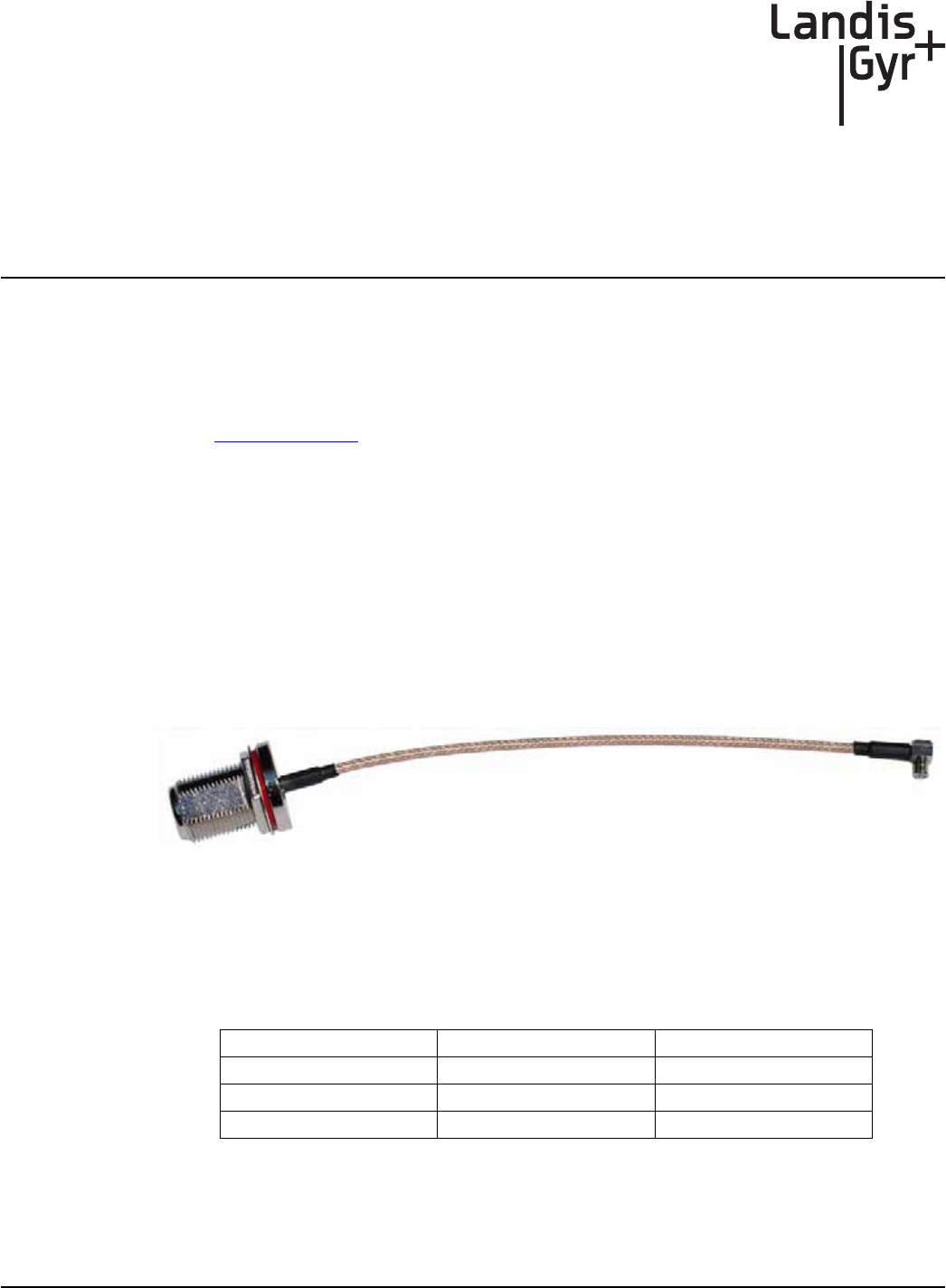
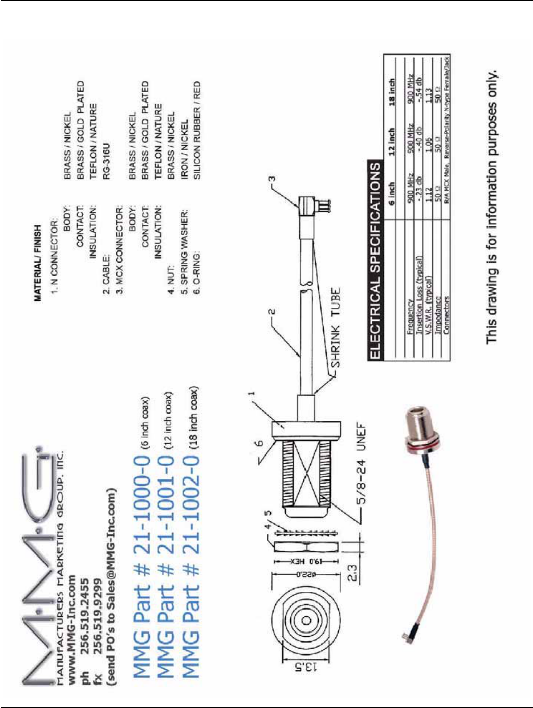
RF External Antenna Cable Specifications
An external antenna is connected to the board via an RF coaxial cable as shown in Figure A - 1. See
page 46 for product data sheet.
Figure A - 1. RF coaxial cable
The cable has a Reverse-Polarity N-Type Female/Jack connector on one end and an MCX Male
connector on the other. This cable is available from MMG in lengths of 6", 12", and 18".
The MMG part numbers and typical insertion loss for these cables are shown in Table A-1:
Table A-1.
Length (inches) Part number Insertion Loss
6 21-1000-0 0.23 dB
12 21-1001-0 0.40 dB
18 21-1002-0 0.54 dB
Appendix A - External Antenna Landis+Gyr
36 98-1546 Rev AA UtiliNet SCADA Single Board Radio
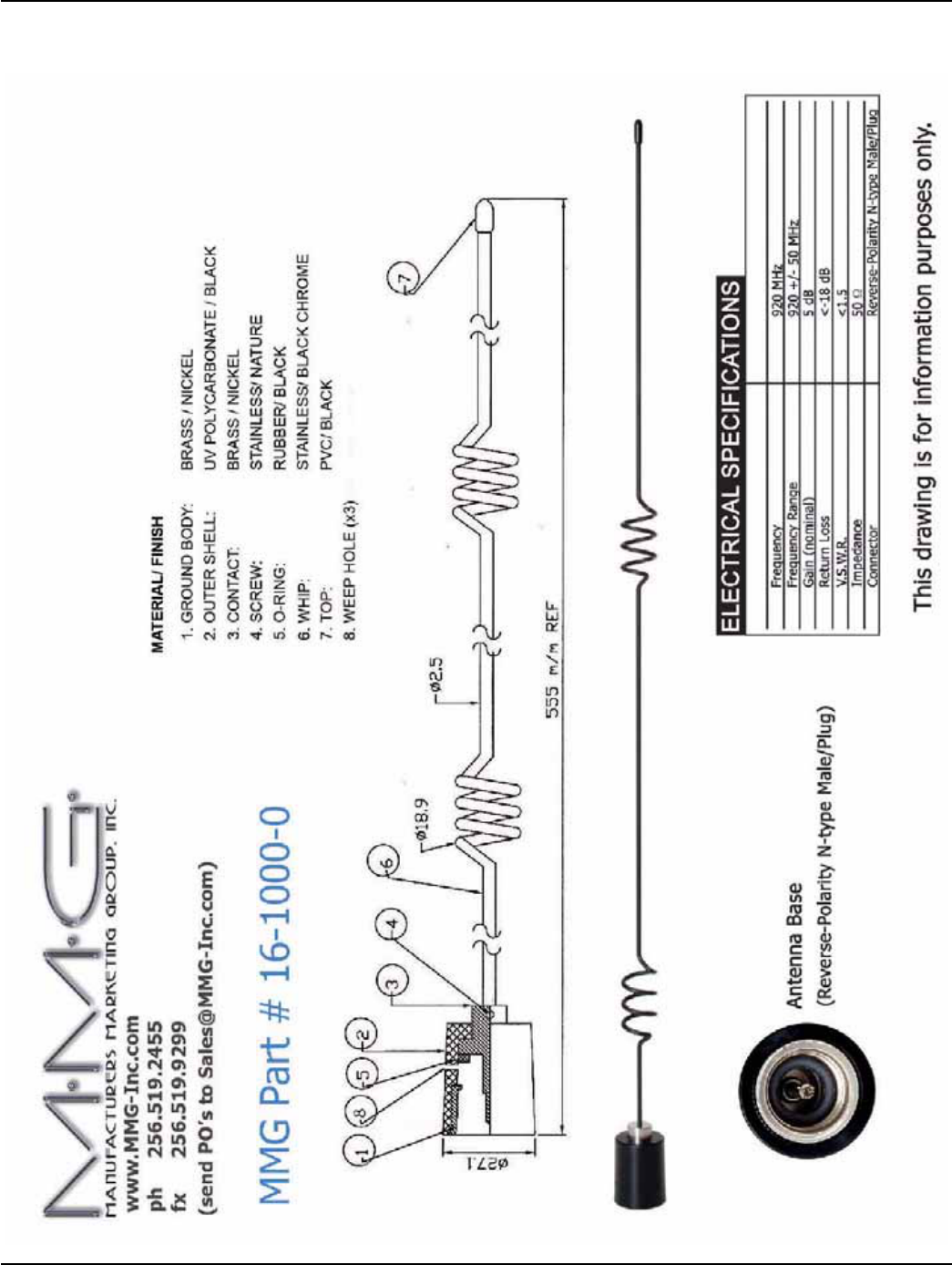
External Antenna Specifications
The External Antenna used to qualify the board is a 5 dB whip (shown in Figure A - 2), made by
MMG. The MMG antenna part number is 16-1000-0. See page 45 for product data sheet.
Figure A - 2. Whip Antenna with N-type Male Reverse-Polarity Connector
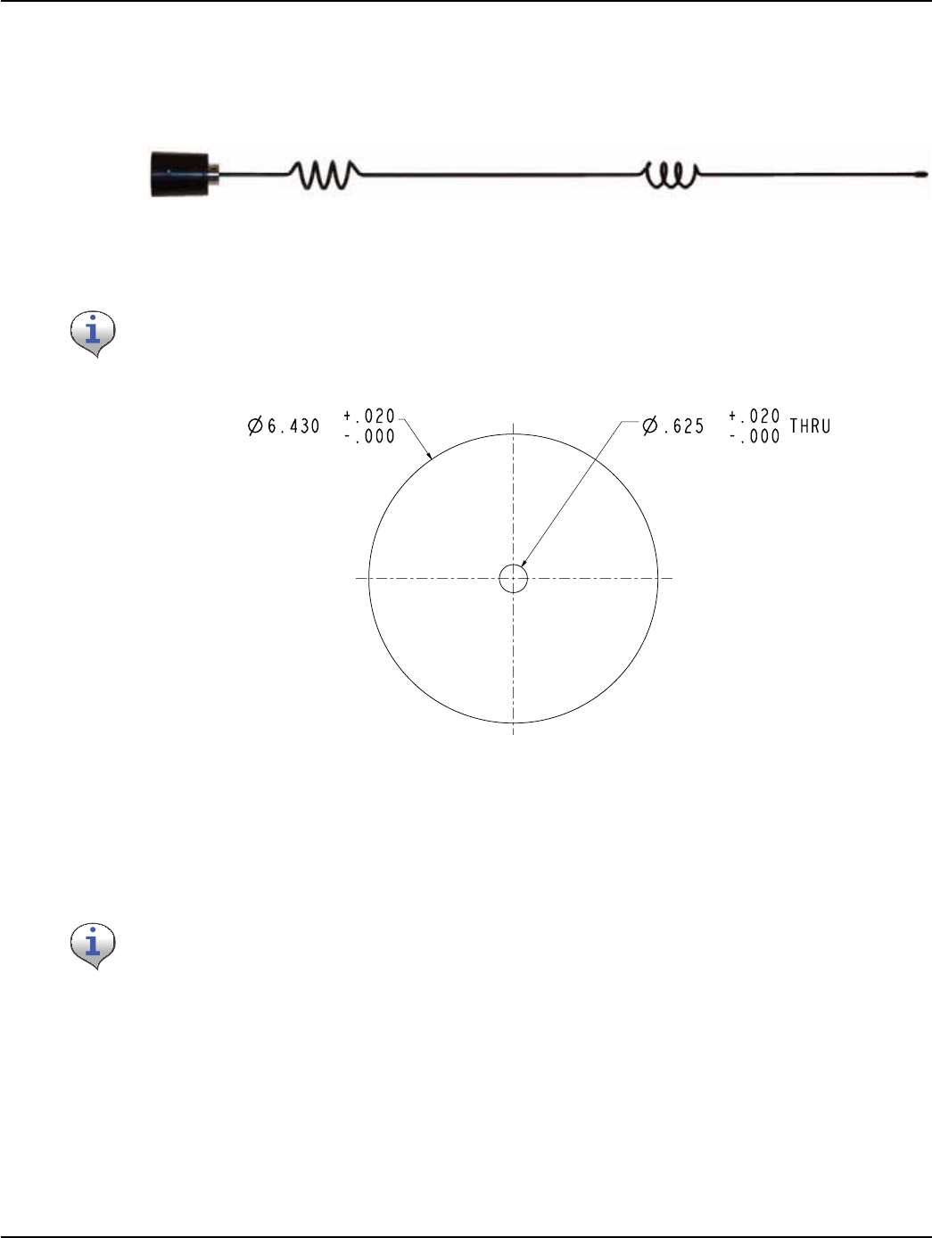
Ground Plane Specifications
Figure A - 3. Ground Plane Specification
If the enclosure for the board is metal and at least 6" across, and the antenna is connected directly to
the enclosure, no ground plane is required, as the enclosure is the ground plane. The radiation pattern
of the approved antenna is of a traditional dipole (RF pattern as a donut). The orientation of the
antenna should be in the vertical position (straight up or straight down), such that the RF pattern is
Omni-directional in the horizontal plane.
Please note this antenna requires a ground plane. The ground plane needs to be at least 6" in
diameter. See Figure A - 3.
““
This antenna's maximum gain is 5 dB and its efficiency is 80%.
Landis+Gyr Appendix A - External Antenna
UtiliNet SCADA Single Board Radio 98-1546 Rev AA 37
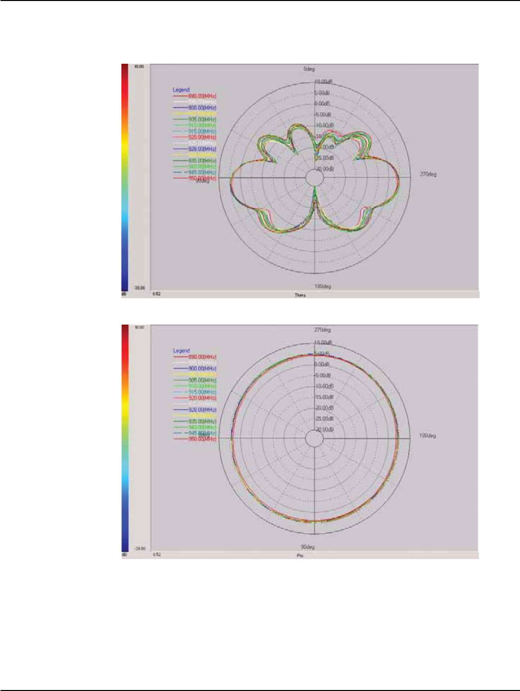
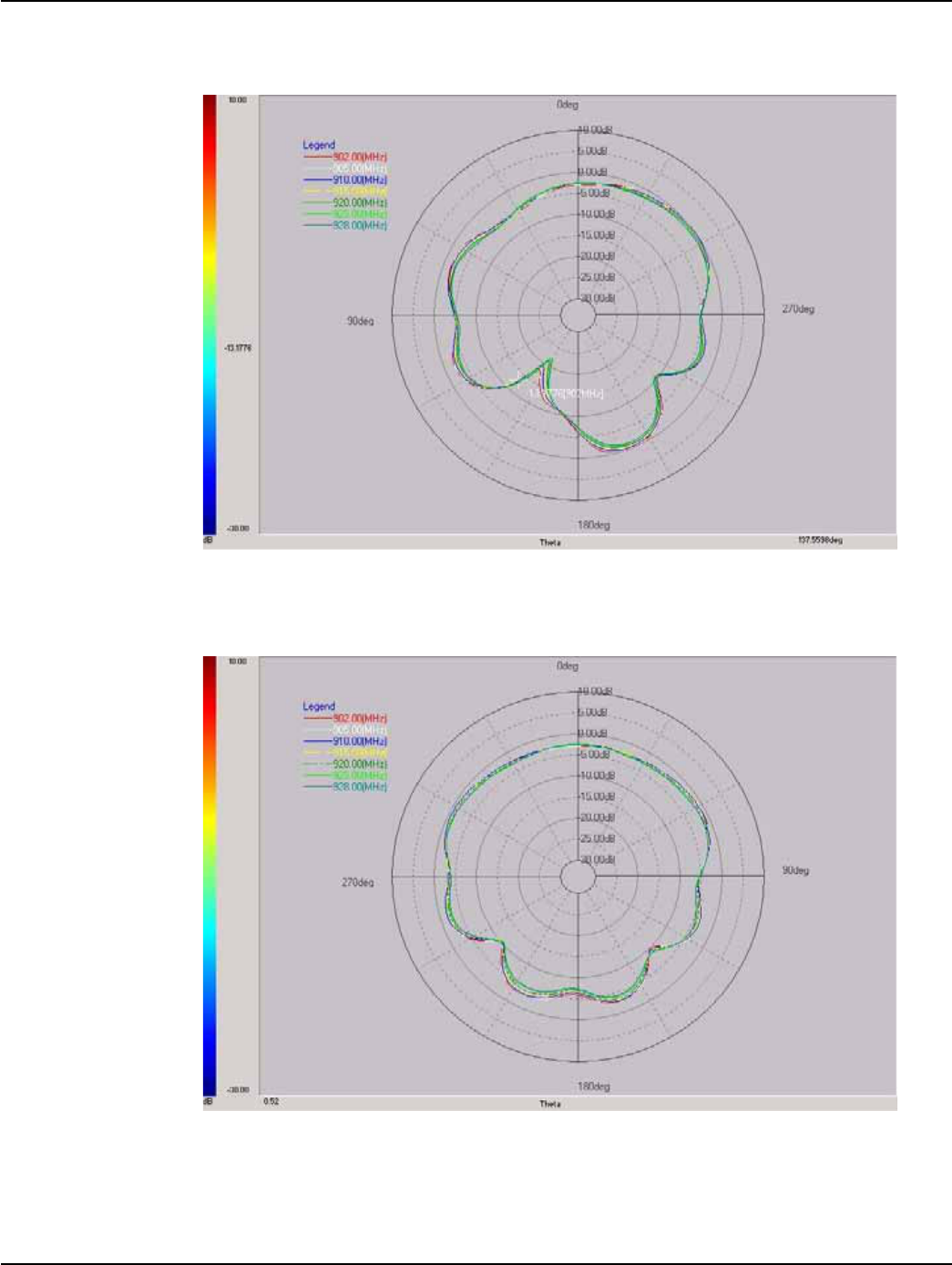
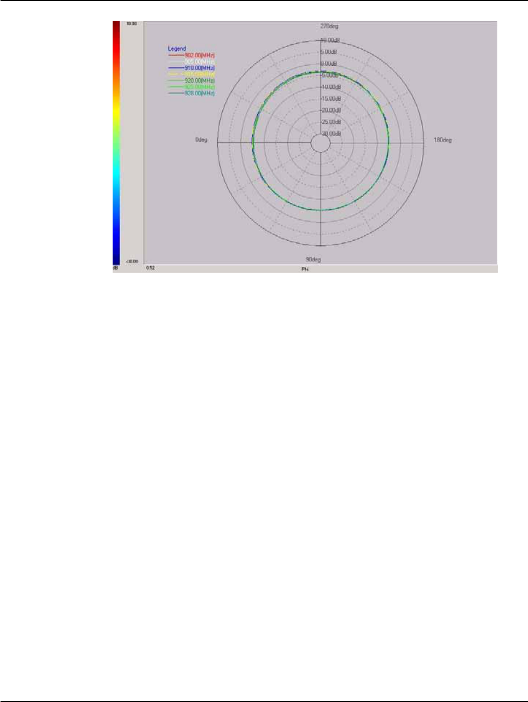
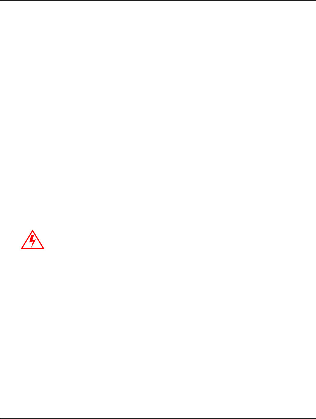
Antenna Radiation Pattern
The antenna's radiation pattern is shown in Figure A - 4 and Figure A - 5.
Figure A - 4. External Antenna Radiation Pattern, Side View
Figure A - 5. External Antenna Radiation Pattern, Top View

Appendix A - External Antenna Landis+Gyr
38 98-1546 Rev AA UtiliNet SCADA Single Board Radio
Identifying a Reverse-Polarized Connector
Figure A - 6. Reverse Polarity and Straight connectors
A reverse polarized coaxial connector alters the standard connector interface by utilizing a male pin
center conductor in a female threaded coupling mechanism and a female basket center conductor in a
male threaded coupling nut mechanism.
This prevents mating with a standard non-polarized connector. This type of connector is required by
FCC part 15.203 rules for modular approval. See Appendix C on page 43.
B
UtiliNet SCADA Single Board Radio 98-1546 Rev AA 39
On-Board Antenna
On-Board Antenna Specifications
The On-Board antenna design is an F-antenna. This design was chosen because its performance is
more broad-band relative to a slot antenna, and its pattern is somewhat Omni-directional. This
antenna's maximum gain is 0 dB and its efficiency is 45%. This version of the product does not allow
an external antenna in conjunction to the on-board antenna.
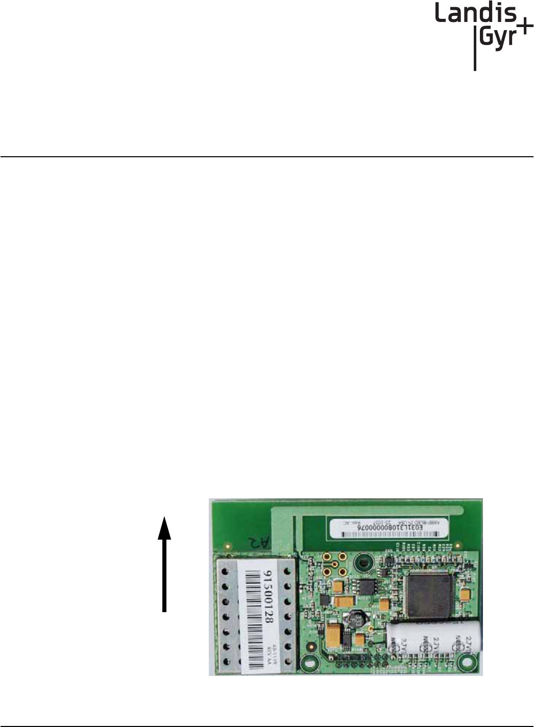
Using the On-Board antenna, the recommended placement of the radio board is at the edge of the
OEM board, with the antenna-side edge of the board extending beyond the edge of the board,
hanging out in free space and facing up as shown below in Figure 1 - 8. If the antenna on the board
does not extend out in free space, then the customer's board will load the antenna and affect the
radiation pattern.
Also, an RF-transparent enclosure must be used (plastic or similar). Do not enclose the board within
a metal box. If a metal box is required to house the assembly, then the external antenna version of the
product should be considered.
The on-board F-antenna's radiation pattern in free space is nearly Omni-directional, but has nulls in
the direction of the 14-pin I/O connector. The best way to visualize the antenna's radiation pattern is
a semi-sphere about the antenna-side edge of the board.
The main radiating element is the long trace running the length of the board. The length of this trace
sets the resonant frequency of the antenna. The thicker F element, parallel to the feed element, is the
return path to ground. The length of the feed element and size of the gap between the feed and
ground elements dictate the match of the antenna.
Figure B - 1. Recommended Board Orientation for Optimal Antenna Performance
Up
Appendix B - On-Board Antenna Landis+Gyr
40 98-1546 Rev AA UtiliNet SCADA Single Board Radio
Using the orientation of the antenna as described above, the antenna's radiation pattern is
shown in the following figures.
Figure B - 2. On-Board Antenna Radiation Pattern, Side View, Looking At the Components
Rotating the board 90° on the Z-axis, relative to the above plot (so the antenna is still up), the
antenna's radiation pattern is shown in Figure B - 3.
Figure B - 3. On-Board Antenna Radiation Pattern, Side View, Looking At the Edge of the Board
The Top View of the antenna's radiation pattern is shown in Figure B - 4.
Landis+Gyr Appendix B - On-Board Antenna
UtiliNet SCADA Single Board Radio 98-1546 Rev AA 41
Figure B - 4. On-Board Antenna Radiation Pattern, Top View

Appendix B - On-Board Antenna Landis+Gyr
42 98-1546 Rev AA UtiliNet SCADA Single Board Radio

C
UtiliNet SCADA Single Board Radio 98-1546 Rev AA 43
Regulatory Compliance
The endpoint module has been designed to meet the following standards:
• FCC - CFR Part 15.247 - Radio Frequency Devices, Subparts A-General and B-Unintentional
Radiators (testing is done at a module level for Modular Approval)
• Industry Canada
FCC - CFR Part 15.247
Both versions of this product are certified with Modular Approval under the same FCC ID number.
Modular Approval is used because the product may be used in a variety of customer assemblies and
configurations. Modular Approval avoids the need to qualify each individual end-product assembly.
However, the customer must adhere to certain rules in order to stay compliant.
For customers using the Internal Antenna version, an FCC ID sticker must be affixed to the outside
of the end-product assembly, stating this Modular SCADA/DA Utilinet board is contained within.
For customers using the External Antenna version, the end-product assembly must also have an FCC
ID sticker stating this Modular SCADA/DA Utilinet board is contained within. In addition, though,
special rules apply to the antenna:
• The antenna (and any associated RF cables connecting the antenna to the board) must be exactly
the same as the one used for certification OR the same type antenna and equal or less gain than
the antenna used for certification.
• The antenna (and associated RF cables) must have unique connectors, so that an end user cannot
connect a non-approved antenna.
The point is that the FCC does not want a customer to attach an antenna with more gain and thereby
possibly exceed the radiated output power and spurious limits. Landis+Gyr chose to use a 5 dB whip
antenna made by MMG (Manufacturer's Marketing Group) to qualify this product. More information
about this specific antenna is found in “External Antenna” on page 35.
This antenna was chosen due to its good performance, availability, relatively low cost, and
comprehensiveness (qualification with this antenna should cover most other antennas available on
the market that could potentially and realistically be used with this product).
If a customer wants to use a different antenna, they are welcome to do so. If the alternate antenna is
the same type (whip) and equal or less gain (5 dB), then it falls under Modular Approval and no
further action is required. However, if the antenna is a different type or more than 5 dB gain, the
customer must re-qualify the assembly for compliance.
The requirement for unique connectors is satisfied by using an MCX Female connector on the
Modular SCADA/DA Utilinet board and a Reverse-Polarity N-Type Male/Plug connector on the
5 dB whip antenna from MMG. MMG also makes the RF coaxial cable to connect this antenna to the
Appendix C - Regulatory Compliance Landis+Gyr
44 98-1546 Rev AA UtiliNet SCADA Single Board Radio
board. The RF cable has a Reverse-Polarity N-Type Female/Jack connector on one end and an MCX
Male connector on the other. More information about this RF cable is found in “External Antenna”
on page 35.
For Class B Devices:
This device complies with Part 15 of the FCC rules. Operation is subject to the following two
conditions:
(1) This device may not cause harmful interference, and
(2) This device must accept any interference received, including interference that may cause
undesired operation.
This equipment has been tested and found to comply with the limits for a Class B digital device,
pursuant to Part 15 of the FCC Rules. These limits are designed to provide reasonable protection
against harmful interference in a residential installation. This equipment generates, uses, and can
radiate radio frequency energy and, if not installed and used in accordance with the Instructions, may
cause harmful interference to radio communications. However, there is no guarantee that
interference will not occur in a particular installation. If this equipment does cause harmful
interference to radio or television reception, which can be determined by turning the equipment off
and on, the user is encouraged to try to correct the interference by one or more of the following
measures:
• Reorient or relocate the receiving antenna.
• Increase the separation between the equipment and receiver.
• Consult Landis+Gyr or an experienced radio technician for help.
RF Exposure
In accordance with FCC requirements of human exposure to radio frequency fields, the radiating
element shall be installed such that a minimum separation distance of 20 centimeters will be
maintained.
Industry Canada
This Class B digital apparatus meets all requirements of the Canadian Interference Causing
Equipment Regulations. Operation is subject to the following two conditions: (1) this device may not
cause harmful interference, and (2) this device must accept any interference received, including
interference that may cause undesired operation.
To reduce potential radio interference to other users, the antenna type and its gain should be so
chosen that the equivalent isotropically radiated power (e.i.r.p.) is not more than that permitted for
successful communication.
Changes or modifications to this device not expressly approved by Landis+Gyr could void the
user's authority to operate the equipment.

Landis+Gyr Appendix C - Regulatory Compliance
UtiliNet SCADA Single Board Radio 98-1546 Rev AA 45
This device has been designed to operate with an antenna having a maximum gain of 5 dBi.
Antennas with a gain greater than 5 dBi are strictly prohibited for use with this device. The required
antenna impedance is 50 ohms.
Cet appareillage numérique de la classe B répond à toutes les exigences de l'interférence canadienne
causant des règlements d'équipement. L'opération est sujette aux deux conditions suivantes: (1) ce
dispositif peut ne pas causer l'interférence nocive, et (2) ce dispositif doit accepter n'importe quelle
interférence reçue, y compris l'interférence qui peut causer l'opération peu désirée.
Pour réduire le risque d'interférer avec d'autres utilisateurs, le type d'antenne et son gain doivent être
choisis de telle sorte que la Puissance Isotrope Rayonnée Equivalente (P.I.R.E) ne soit pas supérieure
à celle autorisée pour une communication réussie.
Cet appareil a été conçu pour opérer avec des antenne ayant un gain maximum de 2dBi. Les antennes
n’ayant pas un gain supérieur à 2 dBi sont strictement interdites pour une utilisation avec cet
appareil. L'impédance d'antenne requise est de 50 ohms.
Landis+Gyr Appendix D - MMG Data Sheets
UtiliNet SCADA Single Board Radio 98-1546 Rev AA 45
MMG Data Sheets
Whip Antenna P/N 16-1000-0
Appendix D - MMG Data Sheets Landis+Gyr
46 98-1546 Rev AA UtiliNet SCADA Single Board Radio
MCX RF Connector P/N 21-1000-0