Landis Gyr CELNTMFMM Cellnet MFMM 902-928 MHz DSSS transmitter User Manual 636165
Landis + Gyr, Inc. Cellnet MFMM 902-928 MHz DSSS transmitter 636165
users manual

Landis+Gyr
Bulletin Number 040917 Rev B S4e-Cellnet MFMM User Manual Page 1 of 12
S4e MFMM Cellnet User Manual
Bulletin 051101
Revision A
Information in this document is subject to change without notice. No part of this document may be reproduced or
transmitted in any form or by any means, electronic or mechanical, for any purpose without the express written
permission of Landis+Gyr Inc.
2004, Landis+Gyr Inc
All rights reserved.
For further information, contact:
Landis+Gyr Inc
2800 Duncan Road
Lafayette, IN 47904 USA
Tel. 800-777-2774
Fax 765-742-0936
DOCUMENT HISTORY
Bulletin: 051101
Revision Date Description
Level Issued
A 11/1/05 Inititial Draft
B 02/03/06 FCC Draft
C 03/06/06 Additional FCC Information Added
Landis+Gyr
Bulletin Number: 040917 Rev B S4E-Cellnet MFMM User Manual Page 2 of 12
TABLE OF CONTENTS
Safety Warnings.................................................................................................................. 3
FCC Information.................................................................................................................. 4
System Overview ................................................................................................................ 6
S4e Meter Overview........................................................................................................... 8
Cellnet MFMM Module Overview..................................................................................... 8
Configuration of the Cellnet MFMM Module ................................................................. 8
Meter Setup.......................................................................................................................... 8
Meter Installation............................................................................................................... 9
Trouble shooting Guide ...................................................................................................10
Use of External Antennas................................................................................................10

Landis+Gyr
Bulletin Number 051101 Rev B S4e-Cellnet MFMM User Manual Page 3 of 12
Safety Warnings
The following safety precautions must be observed during all phases of operation, service, and repair of this
device. Failure to comply with these precautions or with specific warnings elsewhere in these instructions violates
safety standards of design, manufacture, and the intended use of the metering instrument. Landis+Gyr Inc
assumes no liability for the customer's failure to comply with these requirements.
• Warning: Any work on, or near, energized meters, meter sockets, or other metering equipment can
present a danger of electrical shock. All work on this product should be performed only by qualified
electricians and metering specialists in accordance with local utility safety practices, utility requirements
and procedures outlined in Chapter 14 of The Handbook for Electricity Metering (9th edition). The
information contained within this manual is intended to be an aid to qualified metering personnel. It is not
intended to replace the extensive training necessary to handle metering equipment in a safe manner.
• Remove the meter from service prior to installing the antenna isolation kit and/or remote external
antennas.
• Be aware that dangerous voltages exist at several points within the meter when this product is installed on
a meter socket.
• Always disconnect power before meter disassembly, soldering, or replacing components.
The S4e meter is connected directly to line potential. Due to the possibility of the potential lines being reversed,
points accessible with the cover off may be at line voltage.
LINE POTENTIAL IS PRESENT ON THE INCOMING CONNECTORS ON THE MEASUREMENT BOARD
INCLUDING THE BATTERY CONNECTOR.
The connectors have full-length insulators crimped onto each connector, which are shielded by the housing.
However, pulling the connector loose will expose the battery terminals, which may be at line potential. The option
board is connected directly to the main board and may be at a high potential. A Mylar shield prevents touching the
option board. Removing the Mylar shield exposes line voltage. The above warning label affixed to the meter
frame identifies hazards in the meter.
Failure to follow all instructions may result in an unsafe
product that could cause injury or death
CAUTION:
DO NOT OPERATE METER WITHOUT ANTENNA ATTACHED.
OPERATION WITHOUT ANTENNA MAY CAUSE PERMANENT DAMAGE
TO THE CELLNET MFMM MODULE.
Landis+Gyr
Bulletin Number 051101 Rev B S4e-Cellnet MFMM User Manual Page 4 of 12
FCC Information
This device complies with part 15 of the FCC rules. Operation is subject to the following two conditions:
(1) This device may not cause harmful interference, and
(2) This device must accept any interference received, including interference that may cause undesired
operation.
Changes or modifications not expressly approved by Landis+Gyr could void the
user’s authority to operate the equipment.
Note:
This equipment has been tested and found to comply with the limits for a class B digital device, pursuant
to part 15 of the FCC Rules. These limits are designed to provide reasonable protection against harmful
interference in a residential installation. This equipment uses and can radiate radio frequency energy
and, if not installed and used in accordance with the instructions, may cause harmful interference to
radio communications. However, there is no guarantee that interference will not occur in a particular
installation. If this equipment does cause harmful interference to radio or television reception, which can
be determined by turning the equipment off and on, the user is encouraged to try to correct the
interference by one or more of the following measures:
- Reorient or relocate the receiving antenna.
- Increase the separation between the equipment and receiver.
- Connect the equipment into an outlet on a circuit different from that to which the receiver is
connected.
- Consult Landis+Gyr or an authorized technician for help.
Warning:
The antennas used for this transmitter must be installed to provide a separation distance of at least 20 cm
from all persons and must not be co-located or operating in conjunction with any other antenna or
transmitter. End-users and installers must be provided with antenna installation instructions and
transmitter operating conditions for satisfying RF exposure compliance.

Landis+Gyr
Bulletin Number 051101 Rev B S4e-Cellnet MFMM User Manual Page 5 of 12
FCC ID Number
LAN Address
Landis+Gyr
Bulletin Number 051101 Rev B S4e-Cellnet MFMM User Manual Page 6 of 12
Introduction
The S4e Cellnet endpoint brings accuracy, reliability, and low-cost wireless communications to polyphase metering
applications. Leveraging the Cellnet Solid-State Meter Module (MFMM), the S4e Cellnet endpoint transmits 5
minute interval data with 4x redundancy. Some highlights of the S4e Cellnet endpoint are:
• Reliable polyphase AMR
• Advanced metering capable (Demand, TOU, LP)
• Under-cover wireless communications
• Tamper detection
• Outage notification
• High reliability and accuracy
• Field proven
• Economical price
System Overview
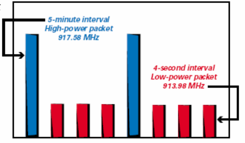
The Cellnet MFMM is a one-way radio frequency communication device that broadcasts using direct sequence
spread spectrum technology over the unlicensed 902-928 MHz frequency band. The Cellnet MFMM also
incorporates an interleave broadcasting technology. Every five minutes, it broadcasts a higher power signal that
carries for about ¾ of a mile. Between these broadcasts, the MFMM also broadcasts every four seconds at a
reduced power that carries for 1,200 feet.
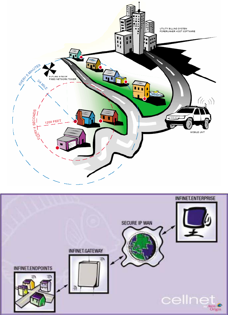
Data can be collected in two ways. The first way employs a drive by solution known as Forerunner. With the
Forerunner solution, information is collected using a receiver that is transported using an automobile. The receiver
is capable of collecting both low power and high power signals, and is designed to be transported up to 30 MPH. If
a customer base becomes dense enough, the Forerunner solution allows for the upgrade to a fixed network.
With a fixed network, the Cellnet MFMM transmits static data and meter data to the Infinet Gateway(s). The
Gateway acts as a concentrator and retransmits information to the Infinet Take-Out point (TOP) point via a WAN,
where it can be moved to a secure IP network.
Landis+Gyr
Bulletin Number 051101 Rev B S4e-Cellnet MFMM User Manual Page 7 of 12
The Cellnet MFMM transmits static data (ID, type, address, etc) and meter data to the Infinet Gateway(s). The
Gateway acts as a concentrator and retransmits information to the Infinet Take-Out point (TOP) point via a WAN,
where it can be moved to a secure IP network.
This is similar to Landis + Gyr’s Forerunner solution. With the Forerunner solution, information is transmitted from
the meters much in the same way. However, information is collected using a receiver that is transported using an
automobile. If a customer base becomes dense enough, the Forerunner solution allows for the upgrade to the
fixed-point receivers.
Landis+Gyr
Bulletin Number 051101 Rev B S4e-Cellnet MFMM User Manual Page 8 of 12
S4e Meter Overview
All S4e meters include wide-dynamic voltage application capability, forms reduction, Service Scan automatic service
recognition, and GyrBox installation diagnostics and monitoring. The S4e is available with several register types,
providing the right functionality for any metering application. The S4e Cellnet MFMM can be ordered with the
following register configurations, however they can not be accessed using the Cellnet MFMM:
AX Active energy, Demand or TOU
AXR 32K Active energy, with a 32K byte load profile recorder
AXR 128K Active energy, with a 128K byte load profile recorder
RX Active and reactive measurement, Demand or TOU
RXR 32K Active and reactive measurement with 32K byte load profile recorder
RXR 128K Active and reactive measurement with 128K byte load profile recorder
An optional input/output board provides up to 2, form C, solid-state relays and up to one external inputs for recording
pulses from a remote source. The 4 relay option board is not available with the S4e Cellnet MFMM meter. One
external input can also be used for real-time rate changes or self-read actuation. The board can be easily added in the
field without the need for special tools or soldering.
For additional information on the S4e meter, consult the
S4/S4e Solid State Meter Instruction/Technical Manual.
Cellnet Module Overview
The S4e meter is modular in its design. The Cellnet MFMM occupies the communications board slot in an S4e meter.
<Insert Cellnet MFMM Picture>
Configuration of the Cellnet Module
The S4e Cellnet MFMM meter is programmed using 1132Prog/1132Com. The Cellnet MFMM module is factory
programmed with a unique LAN Address. It is programmed using RadioShop either serially or over the air.
Meter Setup
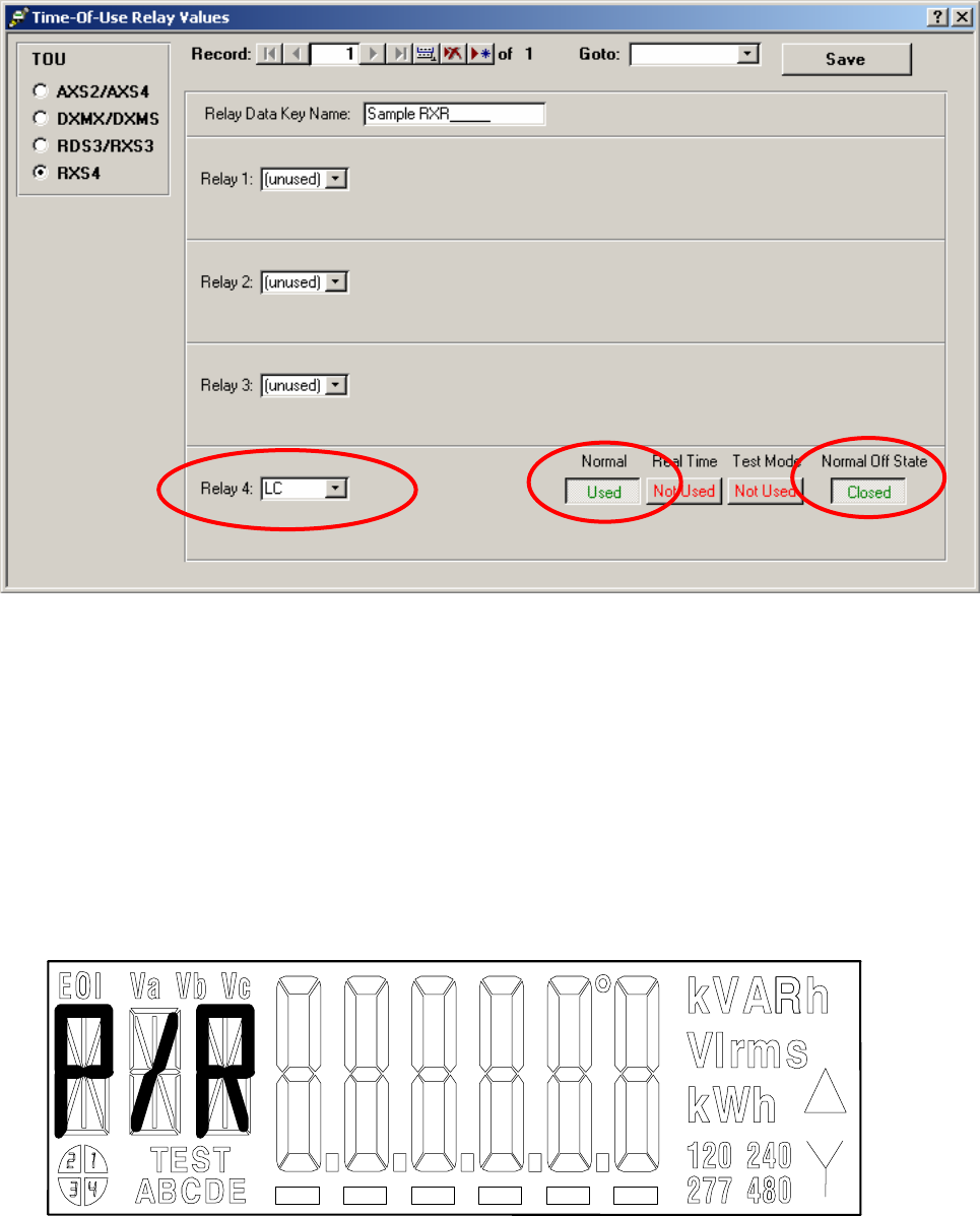
The Cellnet module relies on certain inputs from relay 4 for its operation. As a result, there are a few minimum
programming requirements for the S4 (using 1132Prog). The load control relay activates the relay upon power
up. This relay triggers the Cellnet MFMM module to power up. If the meter is not programmed as shown below,
the Cellnet MFMM module will not power up. A special tool, Cellnet MFMM Radio Tool, was developed to query
and reboot the Cellnet MFMM module.
Relays:
Set Relay 4 to Load Control (“LC”), “Used” in Normal Mode and Normal Off State to “Closed”.
Landis+Gyr
Bulletin Number 051101 Rev B S4e-Cellnet MFMM User Manual Page 9 of 12
Meter Installation
Step 1. Installing S4e Cellnet MFMM Meter
If existing meter is present, follow company procedures for meter removal and installation. (Note: Meter removal
and installation should only be performed by a properly trained technician.)
When the radio is reading information from the meter, the S4e will flash P/R on the display, as shown below.
Step 2. Verifying the S4e Cellnet MFMM Communicates Over the Network

Landis+Gyr
Bulletin Number 051101 Rev B S4e-Cellnet MFMM User Manual Page 10 of 12
Trouble shooting Guide
Symptom
Possible Causes
S4e Meter LCD Display Blank Check voltage to meter
Cellnet MFMM Not Communicating Check Module to Meter Connection
Check relay 4 settings
Use of External Antennas
S4e Cellnet MFMM equipped meters are manufactured with an internal antenna. However, some meter locations
have less than optimal RF reception. Many meter services are ungrounded. Examples of these types of services
include single-phase form 2S, as well as floating 3-wire delta services, 12S and 45S/5S. To improve the reliability
and safety of these floating services, Landis+Gyr has developed an interface for remotely mounted antennas that
allows RF reception under these service conditions. The High Voltage antenna coupling system protects Cellnet
MFMM components from transients reaching up to 7,000 volts. The Landis+Gyr External Antenna Isolation
Solution needs to be installed in the S4e meter in accordance with Landis+Gyr Specifications. Contact the factory
for more information regarding ordering and installing approved external antenna solutions. See the diagram on
the next page. THIS IS FROM THE UTILINET MANUAL. I AM UNSURE ON HOW THE CELLNET’S ANTENNAS
DIFFER.
Technical Features of the S4e Cellnet Meter
S4e Specificiations
Applicable Standards
ANSI C12.1-2001 for electricity metering
ANSI C12.10-1987 for watt-hour meters
ANSI C12.20-1998 for solid-state electricity meters
CAN3-C17-M84 Canadian Specs for approval of electrical meters
CAN3-Z234.4-79 Canadian Specs for all-numeric dates and times
Application Information
Frequency 50 or 60 Hz +/- 5%
Nominal Voltage 120-480 VAC ranging
Operating Voltage 80-115% of nominal
Operating Temperature -40 to +85 C under cover
Humidity Meter Less than or equal to 95% relative humidity, non-
condensing
Rated Accuracy at Unity Power Factor
Transformer-Rated/
Self Contained Meters +/- 0.2%
K-Base Meters +/- 0.5%
Over voltage Withstand
Temporary (.5 sec) 150% rated voltage
Continuous (5 hours) 120% rated voltage
Starting Load:
Class 20 0.005 amps
Class 200 0.050 amps
Class 320 0.050 amps

Landis+Gyr
Bulletin Number 051101 Rev B S4e-Cellnet MFMM User Manual Page 11 of 12
Meter compatibility
FORM CLASS VOLTAGE
Tranformer -Rated: 9S/8S 20 120 to 480 ranging
S-Base 29S 20 120 to 480 ranging
36S 20 120 to 480 ranging
45S 20 120 to 480 ranging
56S 20 120 to 480 ranging
Transformer-Rated: 10A/8A 20 120 to 480 ranging
(A-Base) 36A 20 120 to 480 ranging
45A 20 120 to 480 ranging
Self-Contained 12S 200 120 to 480 ranging
(S-Base) 16S/15S 200 120 to 480 ranging
25S 200 120 to 480 ranging
12SE 320 120 to 480 ranging
16SE/15SE 320 120 to 480 ranging
Self-Contained: 12K 480 120 to 480 ranging
(K-Base) 16K/15K 480 120 to 480 ranging
27K 480 120 to 480 ranging
Self-Contained: 16A/15A 120 120 to 480 ranging
(A-Base)
Residential Meters: 2S 200 120 to 480 ranging
2SE 320 120 to 480 ranging
3S 20 120 or 240
Cellnet Multi-Function Meter Module (MFMM) on the S4e Meter
Applicable Standards:
FCC Parts 15.109, 15.107, 15.205
ANSI/IEEE C62.41-1991
ANSI C12.1-1995, Sections 4.7.2, 4.7.2.5, 4.7.3.2, 4.7.3.1, 4.7.3.14, 4.7.3.8, 4.7.3.3, 4.7.3.4
ANSI C37.90.1-1989
ANSI B109.1-1992
ASTM B117-85
ASTM D999-86
CFR 47 Parts 15, Class B and Class C
IEC 61000-4-2 (Level 4)
IEC 801-4
IPC-A601B, Class 2
NSTA-1A and Mil-STD-810D
Power requirement:
20 mA max steady-state, 200 mA max during transmission at 85°C
Transmitter Power:
Typical ERP (Equivalent Radiated Power) from 19 dBm to 23 dBm depending on model type
Operating environment
Temperature: -40° to +85°C (electric and gas), -30° to +65°C (water)
Humidity: 5% to 95% non-condensing (electric and gas), 0% to 95% condensing (water)
Landis+Gyr
Bulletin Number 051101 Rev B S4e-Cellnet MFMM User Manual Page 12 of 12
Radio Transmitter Specifications:
Transmit Frequency: 902-928 MHz (Spread spectrum, direct sequence)
Transmit Power: High-Power fixed network transmission
Transmission Redundancy: 9x or more