Lanner Electronic Fw 6420 Users Manual
FW-6420 lanner_fw6420
FW-6420 to the manual faa1a4d3-8d66-494c-afe7-cbe663cbcb26
2015-02-09
: Lanner-Electronic Lanner-Electronic-Fw-6420-Users-Manual-570240 lanner-electronic-fw-6420-users-manual-570240 lanner-electronic pdf
Open the PDF directly: View PDF ![]() .
.
Page Count: 48

FW-6420 Series
Mini Desktop VIA Eden low-power
Network Security Appliance
User’s Manual

ii
Copyright and Disclaimers
© Copyright 2004 - Lanner Electronics Inc.
All Rights Reserved
The contents in this publication have been thoroughly checked and considered accurate. The
publisher and manufacturer of this product, Lanner Electronics, is not responsible for any
violation of patents or other rights of third parties resulting from its use. Neither does Lanner
Electronics assume any responsibility for any inaccuracies contained in this manual, nor make
any commitment to keep the information in this document up-to-date.
Lanner reserves the right to make improvements to this document and/or this product at any
given time without notice.
No part of this document may be reproduced, stored in a retrieval system, or transmitted in any
form or by any means (electronic, mechanical, photocopying, recording, or otherwise, without
the formal consent from Lanner.
Trademark Acknowledgments
All products and/or brand names stated in this publication are the trademarks of their rightful
and associated companies.
Radio Frequency Emissions Notice
This equipment has been tested and found to comply with the digital device limits pursuant to
Part 15 of the FCC Rules. These limits are designed to provide reasonable protection against
harmful interference when operate in a commercial environment. This equipment generates,
uses, and can radiate radio frequency energy and, if not installed and used in accordance with
the instruction manual, may cause harmful interference to radio communications. Operation of
this equipment in a residential area may cause harmful interference, in which case the user will
be required to correct the interference at his expense.

iii
Safety Instructions
The following information relates to the safety of installation and maintenance personnel. Read
all instructions before attempting to unpack, install or operate this equipment, especially before
connecting the power adapter.
Please keep the following in mind as you unpack and install this equipment:
Always follow basic safety precautions to reduce the risk of fire, electrical shock and
injury to persons.
Do not apply power into FW-6420 before installation or when disconnecting this
product from its original system setup.
Use only the specified power adapter (output voltage: 12VDC/5A) and make sure the
power adaptor’s plug matches your electrical wall outlet.
To prevent fire or shock hazard, do not expose the unit to rain, moisture or install this
product near water.
Locate a safe and dry location to place this product. Keep it away from wet
surfaces/surroundings.
Never push an object of any kind into this product through openings or empty slots, as
you may damage parts.
Do not attach the power supply cabling to building surfaces. Do not allow anything to
rest on the power cabling or allow it to be abused by persons walking on it.
Distance your working area from moist floors, ungrounded power extension cables, and
unavailable safety grounds.
Avoid installation of this product during a lighting storm.
Damages caused by electrostatic discharge may result in total or intermittent system
failures. To minimize the possibility of ESD damage, an anti-static strap is highly
recommended.
When cleaning or servicing this unit, avoid using highly toxic or aerosol cleaners. Use a
clean damp cloth when wiping its surfaces.
Do not place this device in a tight and sealed location. Place the unit where it can access
sufficient airflow to its vent holes (openings along its sides). Never block or cover these
openings.
Do not disassemble this product on your own.

iv
Getting Technical Assistance
Should you encounter questions or problems with your FW-6420, Lanner Electronics is ready
to assist you within the guidelines of our product support programs. First, check the electronic
product documentation for assistance. If you still cannot find the solution to your problem,
contact Lanner sales team with the following information handy:
FW-6420 model name
Part number
Local network configuration details
The abnormal behavior and/or error messages reported by your network system
Your questions, or a description of the problem you are experiencing
Call, fax, or e-mail Lanner Electronics for technical support.
Phone: 886-2-8692-6060
Fax: 886-2-8692-6101
E-mail: sales@lannerinc.com
About this Manual
This target audience of this manual includes users, administrators and technicians. This
publication is a useful reference when installing, configuring, operating and managing the
FW-6420. This breakdown and short descriptions of this manual’s contents are as follows:
Chapter 1 – Introduction provides an overview of the FW-6420 mini
desktop network security appliance, including its related features,
application usage and technical specifications list. The chapter also
guides users through the pre and post installation process by listing safety
tips plus an overall detailed description of the control board and system
and their vital components.
Chapter 2 – Introduce Hardware Installation
Chapter 3 – Award BIOS Setup
Appendix A –summarizes the specification of the power adapter

v
Table of Contents
Copyright and Disclaimers....................................................................................................ii
Trademark Acknowledgments...............................................................................................ii
Radio Frequency Emissions Notice..................................................................... ii
Safety Instructions............................................................................................... iii
Getting Technical Assistance.............................................................................. iv
About this Manual................................................................................................ iv
Table of Contents ................................................................................................ v
C h a p t e r 1.........................................................................................................................1
Getting Started 1
1.1 Introduction.................................................................................................. 1
1.1.1 Features...............................................................................................................................1
1.2 Technical Specifications.............................................................................. 2
1.3 Packing Contents ........................................................................................ 3
1.4 EM-661 System Board ................................................................................ 4
1.4.1 Mechanical Dimensions .......................................................................................................4
1.4.2 Board Layout........................................................................................................................5
1.4.3 Jumper Settings and I/O Connector.....................................................................................6
1.4.4 Connector Pin Assignments.................................................................................................6
CMOS1:Clear CMOS Data ............................................................................... 6
PLRS1:Power LED,HD LED, Reset, Speaker Connector(11 Pin 2.54mm) ...... 6
FAN1 : 3 Pin FAN Connector........................................................................... 7
LANA1~4: Type 1 ( RJ-45 ).............................................................................. 7
PRJK1 : 3 Pin Power Input Jack........................................................................ 7
COMA1: RS-232 Serial Port #1 Connector (D-Sub) ....................................... 7
VGB1 : External VGA Connector (2X6 Header 2.54mm ) ............................... 7
PKMB1: PS/2 Keyboard & Mouse Connector (2x4 Header 2.54mm )............. 8
USBB1: Dual Connector ................................................................................... 8
IDEA1 : IDE Interface Connector ( 44Pin 2.0mm Pitch Header ) .................... 9
CF1: Compact Flash Connector ...................................................................... 10
LPTA1: Parallel Connector (26 Pin 2.00mm Pitch Header).............................11
PCIB1:124-pin Mini PCI Sockets ................................................................... 12
RSW1: 4-pin Software Reset Switch............................................................... 13
1.5 FW-6420 Mini Desktop Firewall Mechanisms ............................................. 14
1.5.1 Mechanical Dimensions .......................................................................................................14
1.5.2 Face Panel...........................................................................................................................14
1.5.3 Rear View.............................................................................................................................16
C h a p t e r 2.......................................................................................................................17
FW-6420 Hardware Installation Guide..............................................................................17
2.1 Hardware Installation Guide........................................................................ 17
Chapter 3..............................................................................................................................20
Award BIOS Setup..............................................................................................................20
3.1 Running AWARD BIOS ................................................................................. 20
3.2 CMOS Setup Utility ....................................................................................... 21
3.3 Standard CMOS Setup.................................................................................. 23
3.4 Advanced BIOS Features Setup ................................................................... 26
3.5 Advanced Chipset Setup............................................................................... 27
3.6 Integrated Peripherals Setup......................................................................... 29
3.7 Power Management Setup........................................................................... 30

vi
3.8 PCI Plug and Play Setup............................................................................... 32
3.9 PC Health Status........................................................................................... 34
3.10 Load Optimal Defaults................................................................................. 35
3.11 Supervisor / User Password........................................................................ 36
3.12 Save & Exit Setup ....................................................................................... 37
3.13 Exit Without Saving ..................................................................................... 37
Appendix A...........................................................................................................................38
A p p e n d i x B...................................................................................................................39
Console Redirection ............................................................................................................39
Terms and Conditions........................................................................................................................ 40
Warranty Policy 40
RMA Service 40
1
C h a p t e r 1
Getting Started
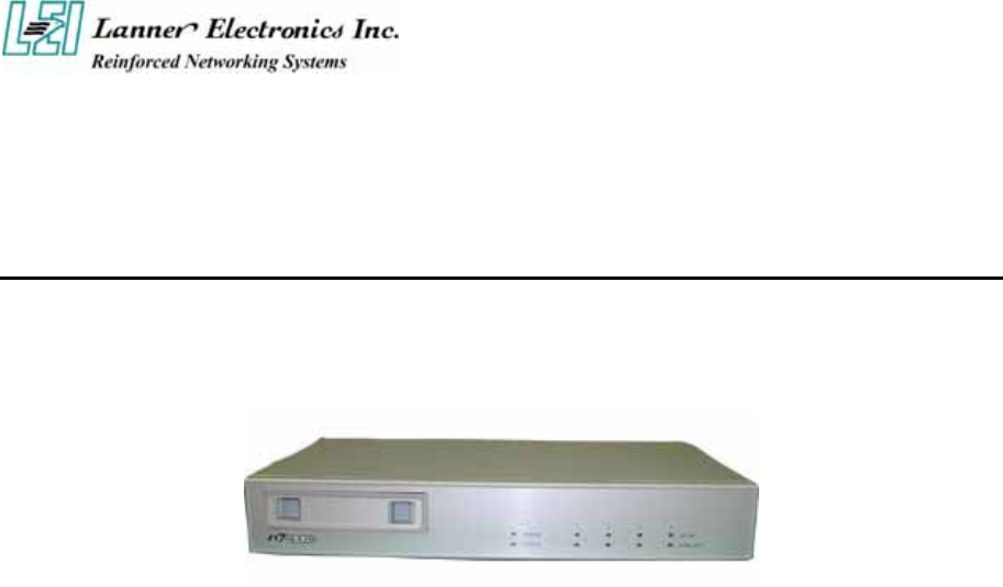
1.1 Introduction
Figure 1 – FW-6420 Outlook
Designed for the Small and Medium-sized Businesses(SMB) in mind, the FW-6420 is a
powerful, yet flexible mini-desktop solution for the SMB network security market. The
FW-6420 is embedded with a VIA Eden low power CPU, running at 400MHz or 1GHz. It is
also equipped with four Ethernet ports each with its own Realtek RTL8139C+ and supports
Compact Flash Type II, PCI and Mini PCI. The FW-6420 is the ideal solution for developers,
who require a speedy Time-to-Market network security product for the fast growing network
security market. With this network security device you can provide a number of networking
security functions that werer previously only available for the larger Enterprises, such as
Virtual Private Network (VPN), Firewall, Multi-Homing and many more.
1.1.1 Features
Listed below are the key features of FW-6420.
Supports 2.5” HDD
Supports VIA Eden ESP 400MHz or 1GHz processor
Supports one DDR DIMM socket (184-pin);up to 1 GB
Supports four 10/100Mbps Ethernet ports, each with an independent Realtek
RTL8139C+ chipset
Supports Compact Flash, Serial(RS-232), PCI and Mini PCI.
One software reset Button
Mini desktop network security solution
Suitable Network applications; Virtual Private Network(VPN), Firewall, IDS,
Multi-Homing, Residential Gateway, Router and many more…
2
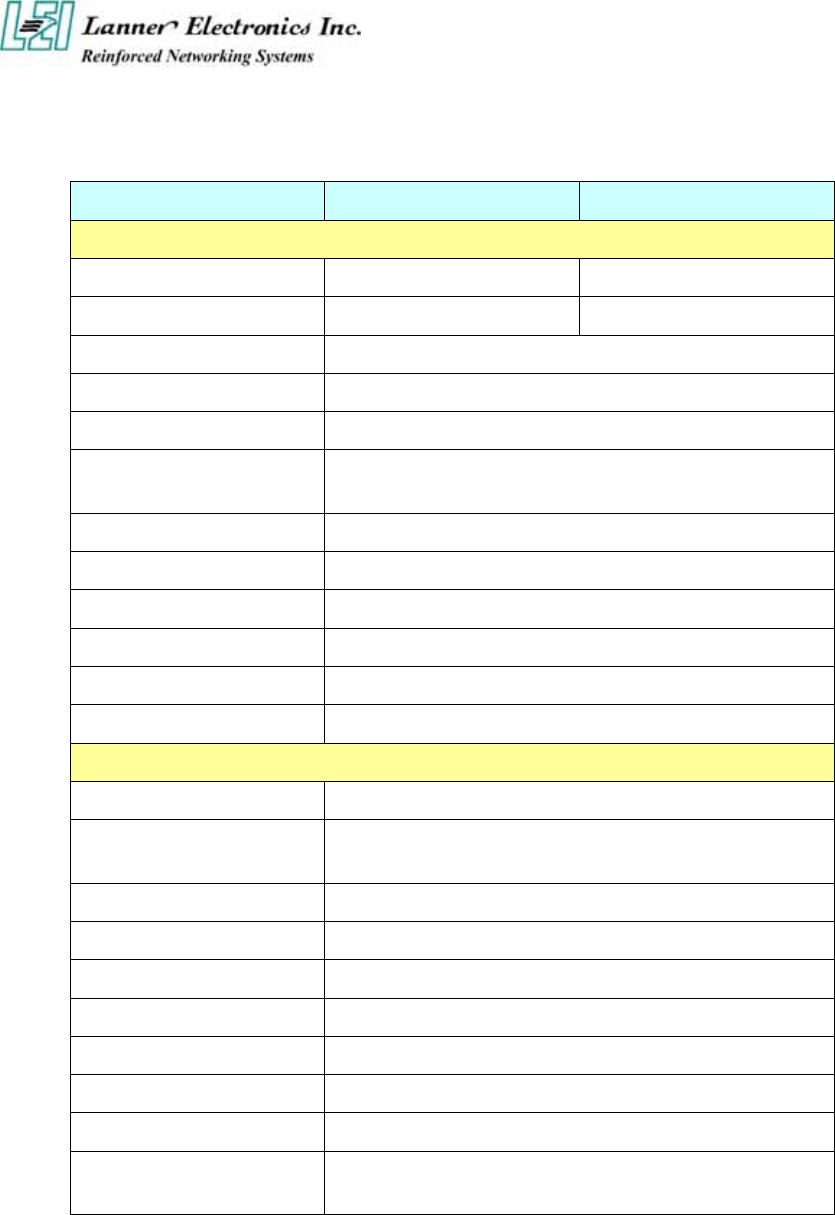
1.2 Technical Specifications
Model Name FW-6420B FW-6420E
SBC
SBC EM-661B EM-661E
CPU VIA Eden 400 MHz VIA Eden 1GHz
Chipset VIA CLE266 VT8623/VT8235
BIOS Award BIOS
Memory One 184 pin DDR DIMM, up to 1GB
Network interface Four Realtek RTL8139C+, support 10/100Mbps
Ethernet with four external RJ-45 Connectors
SSD One CompactFlash TypeII Socket
I/O Interface One DB-9 RS-232 connector
Expansion Slot One PCI and One Mini-PCI slot
Reset One reset button for software reset
RTC Internal RTC with LI battery
Power One power jack 12V, 5A, 2.5mm
Mechanical/ Environmental
Form Factor Slim destop
LED Indicator 1*Power, 1*Status, 4*LAN speed 10/100Mbps,
4*LAN link/Active
Operating Temperature 0 oC – 40 oC
Storage Temperature -20 oC – 70 oC
Humidity 5% - 95% RH, non-condersing
Chassis Material Steel
Dimension(H x W x D) 50 x 330 x 161.7 mm
Net Weight 2 KGS
Certification CE, FCC CLASS B
Software support Linux 6.5 and above, Windows
95/98/2000/2003/ME/XP

3
1.3 Packing Contents
Carefully unpack your package and make sure that you have the following items.
FW-6420 Network security Platform
Console cable
1.8 meters long cross-over Ethernet cable
1.8 meters long straight-through Ethernet cable
Face panel name plate label
Power adapter
Power cable
Drivers and User’s Manual CD
If you find anything missing or damaged, promptly contact your dealer for assistance.
4
1.4 EM-661 System Board
EM-661 is the system board bundled with the FW-6420 Network security platform. The
succeeding sections list all EM-661 related jumper settings and connector pin assignments.
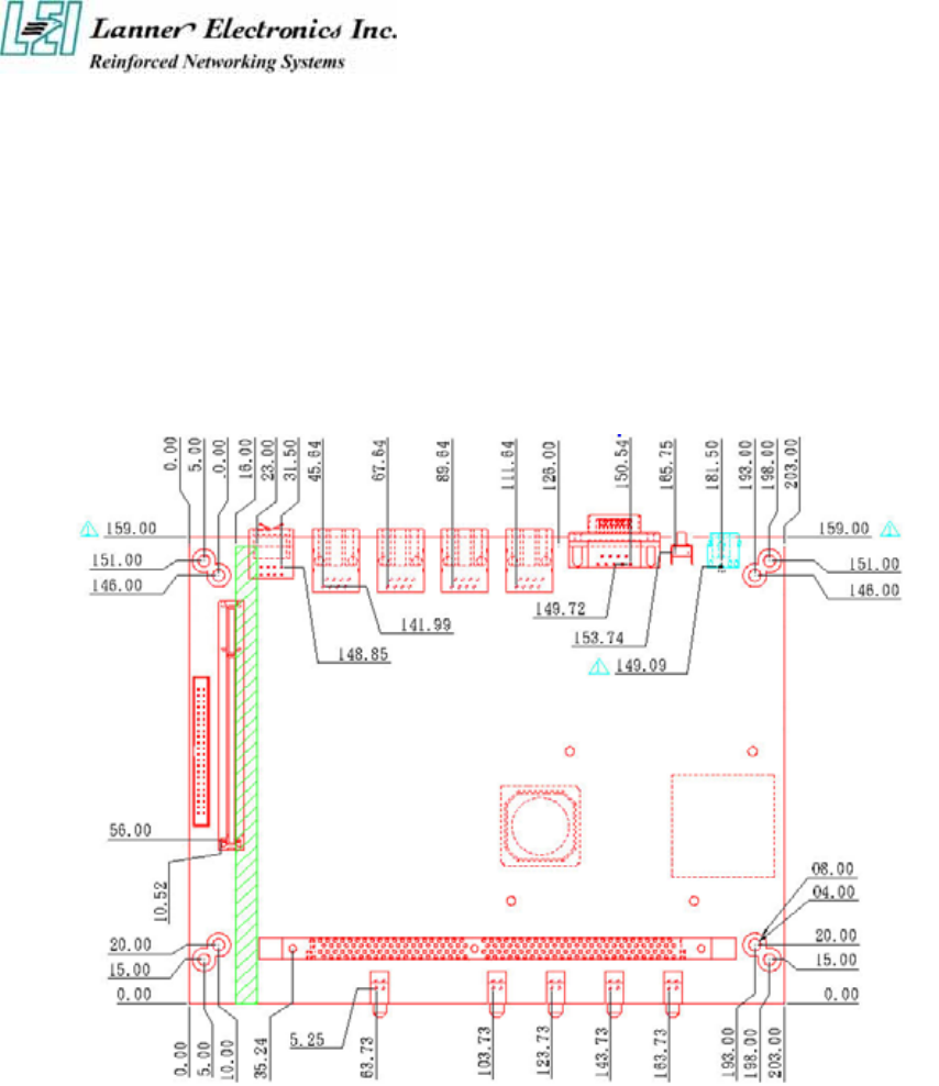
1.4.1 Mechanical Dimensions
Figure 2 – EM-661 Control Board Dimensions (units in mm)
5
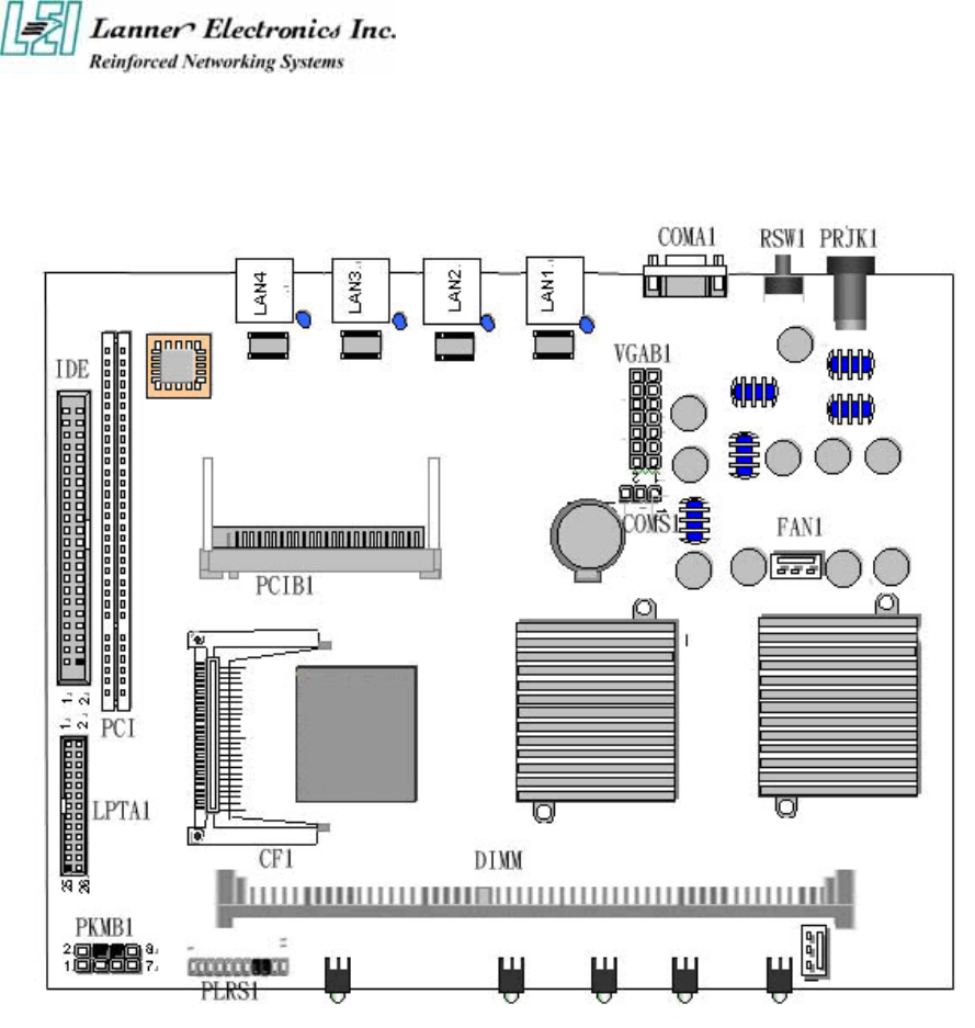
1.4.2 Board Layout
Figure 3 – EM-661 Jumpers and Connectors
6
1.4.3 Jumper Settings and I/O Connector
The onboard jumper settings and I/O connector of EM-661 are custom-tailored to fit the
FW-6420 functionality. Changing the jumper settings may result in system malfunction or
unforeseen damages.
Jumper Settings and I/O Connector Summary for EM-661
JUMPER FUNCTION
CMOS1 Clear CMOS Data
PLRS1 Power LED,HD LED, Reset, Speaker Connector(11 Pin 2.54mm)
FAN1 3 Pin Fan Connector
LAN1-4 LAN Connector
PRJK1 3 Pin Power Input Jack
COMA1 RS-232 Serial Port #1 Connector ( D-Sub )
PKMB1 PS/2 Keyboard & Mouse Connector
VGAB1 External VGA Connector ( Header )
LPTA1 Parallel Connector
USBB1 Dual USB Connector
CF1 Compact Flash Connector
IDEB1 IDE Interface Connector
PCIB1 124 Pin Mini PCI Socket
1.4.4 Connector Pin Assignments
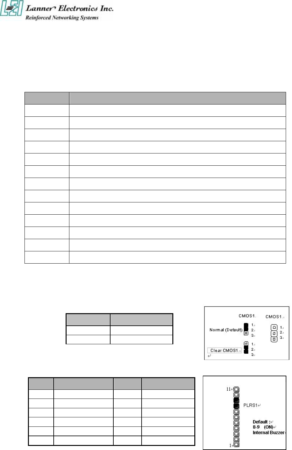
CMOS1:Clear CMOS Data
COM1 Description
1-2 Normal (Default)
2-3 Clear CMOS
PLRS1:Power LED,HD LED, Reset, Speaker Connector(11 Pin 2.54mm)
Pin No. Description Pin No. Description
1 Power LED + 2 Power LED -
3 Ground 4 HDD LED +
5 HDD LED - 6 RESET SW +
7 RESET SW – (GND) 8 External Speaker -
9 Internal Buzzer - 10 NC
11 External Speaker +
7
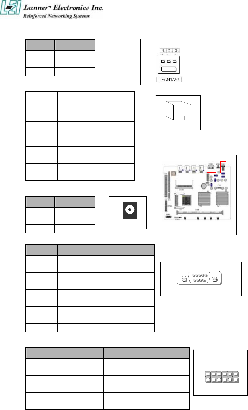
FAN1 : 3 Pin FAN Connector
Pin No. Description
1 Ground
2 +12V
3 FAN Status
LANA1~4: Type 1 ( RJ-45 )
Description
Pin No. Fast E-Net
1 TX+
2 TX-
3 RX+
4 T45
5 T45
6 RX-
7 T78
8 T78
PRJK1 : 3 Pin Power Input Jack
COMA1: RS-232 Serial Port #1 Connector (D-Sub)
Pin No. Description
1 Data Carrier Detect (DCDA #)
2 Receive Data (RXDA)
3 Transmit Data (TXDA)
4 Data Terminal Ready (DTRA #)
5 Ground (GND)
6 Data Set Ready (DSRA #)
7 Request To Send (RTSA #)
8 Clear To Send (CTSA #)
9 Ring Indicator (RIA #)
VGB1 : External VGA Connector (2X6 Header 2.54mm )
Pin No. Description Pin No. Description
1 R 2 Ground
3 G 4 Ground
5 B 6 Ground
7 H-SYNC 8 Ground
9 V-SYNC 10 Ground
11 Detect-display Data 12 Detect-display CLOCK
Pin No. Description
1 Ground
2 Ground
3 +12V
LANA1
PRJK1
COMA1
15
9 6
11
12 2
1
VGB1
8
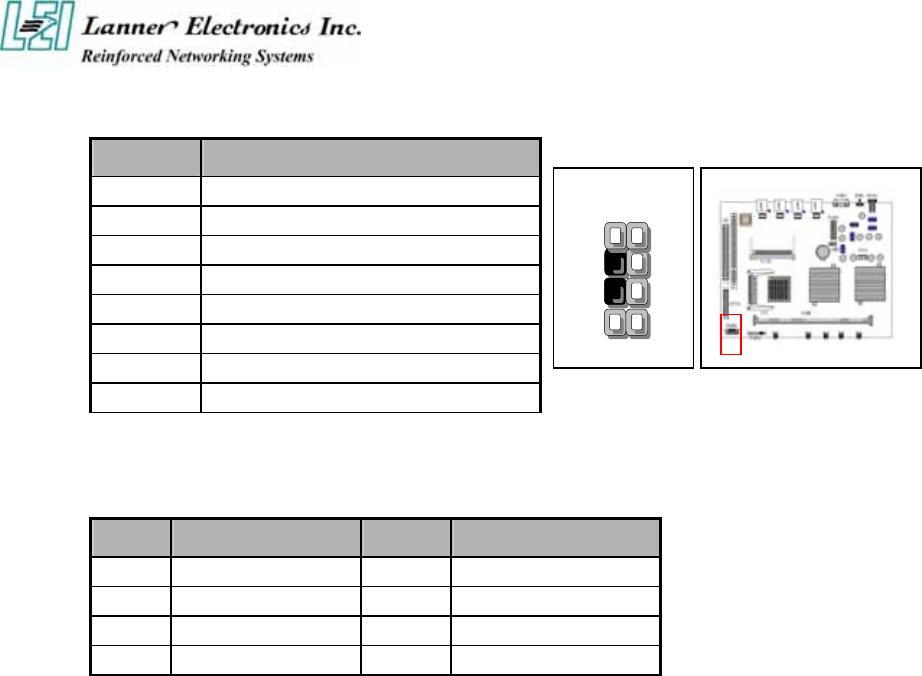
PKMB1: PS/2 Keyboard & Mouse Connector (2x4 Header 2.54mm )
Pin No. Description
1 KBCLK)
2 Ground
3 NC
4 KBDATA
5 NC
6 MSDATA
7 MSCLK
8 VCC
USBB1: Dual Connector
Pin No. Description Pin No. Description
1 USB_VCC 2 USBD0-
3 USBD0+ 4 Ground
5 USB_VCC 6 USBD1-
7 USBD1+ 8 Ground
2
4
6
8
1
3
5
7
PKMB1
9
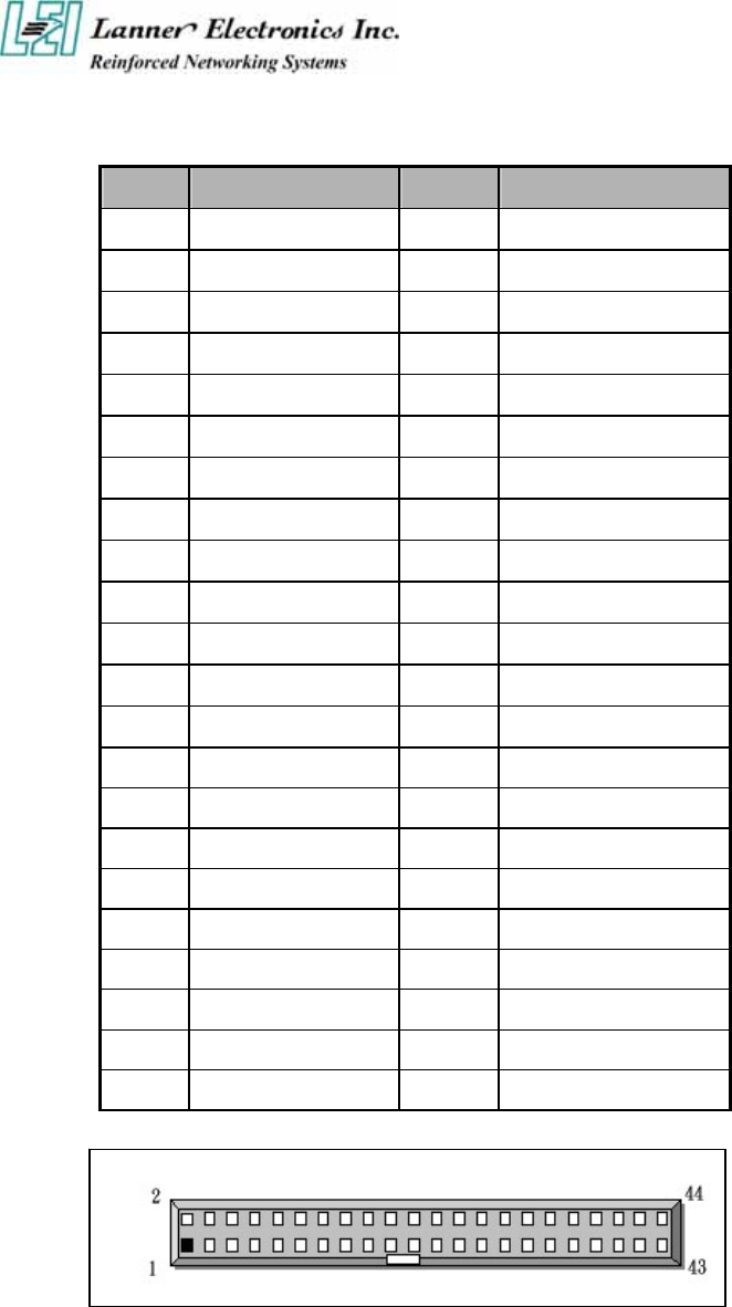
IDEA1 : IDE Interface Connector ( 44Pin 2.0mm Pitch Header )
Pin No. Description Pin No. Description
1 Reset # 2 Ground
3 Data 7 4 Data 8
5 Data 6 6 Data 9
7 Data 5 8 Data 10
9 Data 4 10 Data 11
11 Data 3 12 Data 12
13 Data 2 14 Data 13
15 Data 1 16 Data 14
17 Data 0 18 Data 15
19 Ground 20 NC
21 DMA REQ# 22 Ground
23 IOW # 24 Ground
25 IOR # 26 Ground
27 IOCHRDY 28 Ground
29 DMA ACK # 30 Ground
31 Interrupt 32 NC
33 SA 1 34 NC
35 SA 0 36 SA 2
37 HDC CS 0# 38 HDC CS 1#
39 HDD Active 40 Ground
41 VCC 42 VCC
43 Ground 44 NC
10
CF1: Compact Flash Connector
Pin No. Description Pin No. Description
1 Ground 26 CD1-
2 DATA3 27 DATA11
3 DATA4 28 DATA12
4 DATA5 29 DATA13
5 DATA6 30 DATA14
6 DATA7 31 DATA15
7 CE1# 32 CE2#
8 A10 33 VS1#
9 OE# 34 IOR#
10 A9 35 IOW#
11 A8 36 WE#
12 A7 37 READY#
13 CFVCC3 38 CFVCC3
14 A6 39 CSEL
15 A5 40 VS2#
16 A4 41 RESET
17 A3 42 WA IT #
18 A2 43 INPACK#
19 A1 44 REG#
20 A0 45 DASP#
21 DATA0 46 DIAG#
22 DATA1 47 DATA8
23 DATA2 48 DATA9
24 WP 49 DATA10
25 CD2- 50 Ground
25 1
50 26
CF1
11
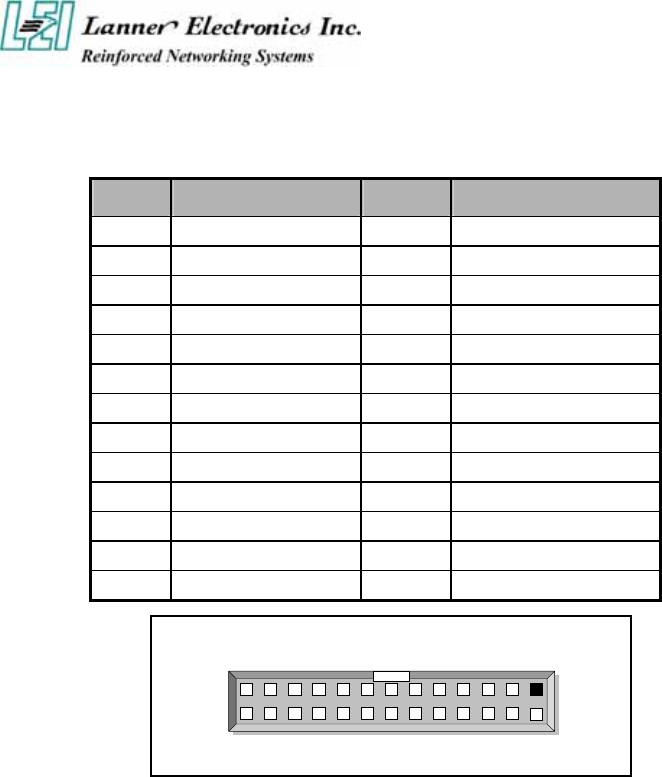
LPTA1: Parallel Connector (26 Pin 2.00mm Pitch Header)
Pin No. Description Pin No. Description
1 Strobe # 2 Auto Form Feed
3 Data0 4 Error #
5 Data1 6 Initialize #
7 Data2 8 Printer Select IN #
9 Data3 10 Ground
11 Data4 12 Ground
13 Data5 14 Ground
15 Data6 16 Ground
17 Data7 18 Ground
19 Acknowledge # 20 Ground
21 Busy 22 Ground
23 Paper Empty 24 Ground
25 Printer Select 26 KEY
LPTA1 1
2
25
2 6

12
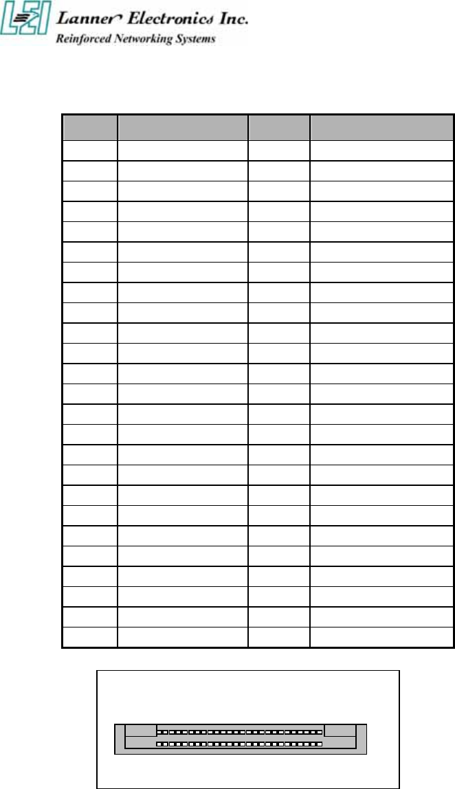
PCIB1:124-pin Mini PCI Sockets
Pin No. Description Pin No. Description
1 TIP 2 RING
3 8PMJ-3 4 8PMJ-1
5 8PMJ-6 6 8PMJ-2
7 8PMJ-7 8 8PMJ-4
9 8PMJ-8 10 8PMJ-5
11 LED1_GRNP 12 LED2_YELP
13 LED1_GRNN 14 LED2_YELP
15 CHSGND 16 RESERVED
17 INT-B 18 +5V
19 +3.3V 20 INT-A
21 RESERVED 22 RESERVED
23 GROUND 24 3.3VAUX
25 CLK 26 RST
27 GROUND 28 +3.3V
29 REO 30 GNT
31 +3.3V 32 Ground
33 AD31 34 PME
35 AD29 36 RESERVED
37 Ground 38 AD30
39 AD27 40 +3.3V
41 AD25 42 AD28
43 RESERVED 44 AD26
45 C_BE-3 46 AD24
47 AD23 48 IDSEL
49 Ground 50 Ground
51 AD21 52 AD22
53 AD19 54 AD20
55 Ground 56 PAR
57 AD17 58 AD18
59 C_BE-2 60 AD16
61 IRDY 62 Ground
63 +3.3V 64 FRAME
65 CLKRUN 66 TRDY
67 SERR 68 STOP
69 Ground 70 +3.3V
71 PERR 72 DEVSEL
73 C_BE-1 74 Ground
75 AD14 76 AD15
77 Ground 78 AD13
79 AD12 80 AD11
81 AD10 82 Ground
- More -
13
Pin No. Description Pin No. Description
83 Ground 84 AD9
85 AD8 86 C_BE-0
87 AD7 88 +3.3V
89 +3.3V 90 AD6
91 AD5 92 AD4
93 RESERVED 94 AD2
95 AD3 96 AD0
97 +5V 98 RESERVED-WIP
99 AD1 100 RESERVED-WIP
101 Ground 102 Ground
103 AC_SYNC 104 M66EN
105 AC_SDATA_IN 106 AC_SDATA_OUT
107 AC_BIT_CLK 108 AC_CODEC_ID0
109 AC_CODEC_ID1 110 AC_RESET
111 MOD_AUDIO_MON 112 RESERVED
113 AUDIO_GND 114 Ground
115 SYS_AUDIO_OUT 116 SYS_AUDIO_IN
117 SYS_AUDIO_OUT GND 118 SYS_AUDIO_IN GND
119 AUDIO_GND 120 AUDIO_GND
121 RESERVED 122 MPCIACT
123 VCC5VA 124 3.3AUX
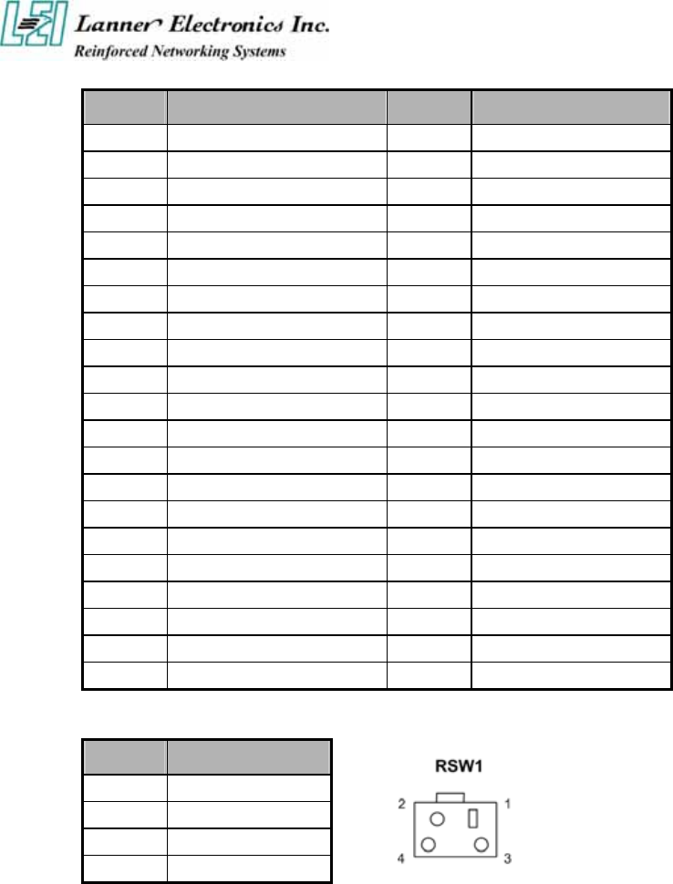
RSW1: 4-pin Software Reset Switch
Pin No. Description
1 Reset signal
2 Ground
3 Ground
4 Ground

14
1.5 FW-6420 Mini Desktop Firewall Mechanisms
This section of the manual describes the mechanical and device nomenclature of FW-6420.
1.5.1 Mechanical Dimensions
The illustration below identifies the physical measurements of the FW-6420.
Figure 4 – FW-6420 Chassis
1.5.2 Face Panel
LED Indicator PCI Slot

15
Figure 5 – FW-6420 Face Panel
Face Panel LED Status and Behavior
The following table lists and explains the behavior of each LED on the FW-6420 front panel.
LED Color Status Description
Green On When FW-6420 power is switched ON
Power N/A Off No power connected
Status Green/RED Programmable via GPIO
Green LAN Speed 100 Mbps
Ethernet Ports
10/100 N/A LAN Speed 10 Mbps
On This LED indicate that the port continuously
connection
Ethernet Ports
Link/ACT Green Flash This LED will flash when the data is transmitted on the
port.
GPIO definition
VT8235 GPIO
Name Color Condition
08 09 10
Description
RED Off 0 0 0
RED 0.1 sec Blink 0 1 0
RED 0.5 sec Blink 1 0 0
RED On 1 1 0
Green Off 0 0 1
Green 0.1 sec Blink 0 1 1
Green 0.5 sec Blink 1 0 1
User Define
Status
Green On 1 1 1 System Ready ON
Notes Lanner provide the LED Status Sample code in the Manual/Driver CD.
The path is \Driver\LED_Sample_Code

16
1.5.3 Rear View
Figure 6 – FW-6420 Rear View
Console Port: via the console port cable, this connector attaches FW-6420 to
the host PC . The default baud rate is 38400.
LAN Connector: Ethernet RJ-45 connector, connected to networking environment
using a RJ-45 Ethernet cable
DC Power Jack: Power connector, connected to the power adapter packed with
the FW-6420
Reset Button: This is software reset button. It is defined by VT8235 GPIO 11.
Faulty or improper use of the power adaptor may cause permanent damage to the
power supply and the FW-6420. Plug the adaptor to an electrical wall outlet that
matches its specifications.
C h a p t e r 2
FW-6420 Hardware Installation Guide
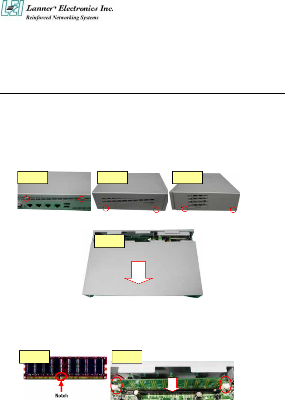
2.1 Hardware Installation Guide
- Removing the Top Cover
Step 1 : Unscrew two screws from back of the system.
Step 2 : Unscrew two screws from right of the system.
Step 3 : Unscrew two screws from left of the system.
Step 4 : Pull the top panel up as shown in below graph. Put the top panel in a safe place.
- System Memory
Step 1: The DIMM slot has a notch, the DIMM memory module only fit in one direction.
Step 2: Align the memory notch to the module and push the memory into the DIMM socket
vertically.
Ste
p
1 Ste
p
2 Ste
p
3
Ste
p
4
Ste
p
1 Ste
p
2

- Installing Hard Disk Drive
Step 1: Take off four screws from the hard disk bracket.
Step 2: Moving the hard disk bracket.
Step 3: Insert the hard disk in the bracket and screwing four screws with the hard disk
together from both sides.
Step 4: Install the 44-pin hard disk cable to the hard drive and screw four screws in the
hard disk bracket.
- Installing Compact Flash Card
Step 1: Insert the compact flash card into the slot carefully as shown in the picture.
Ste
p
1 Ste
p
2
Ste
p
3
Ste
p
4
Ste
p
1
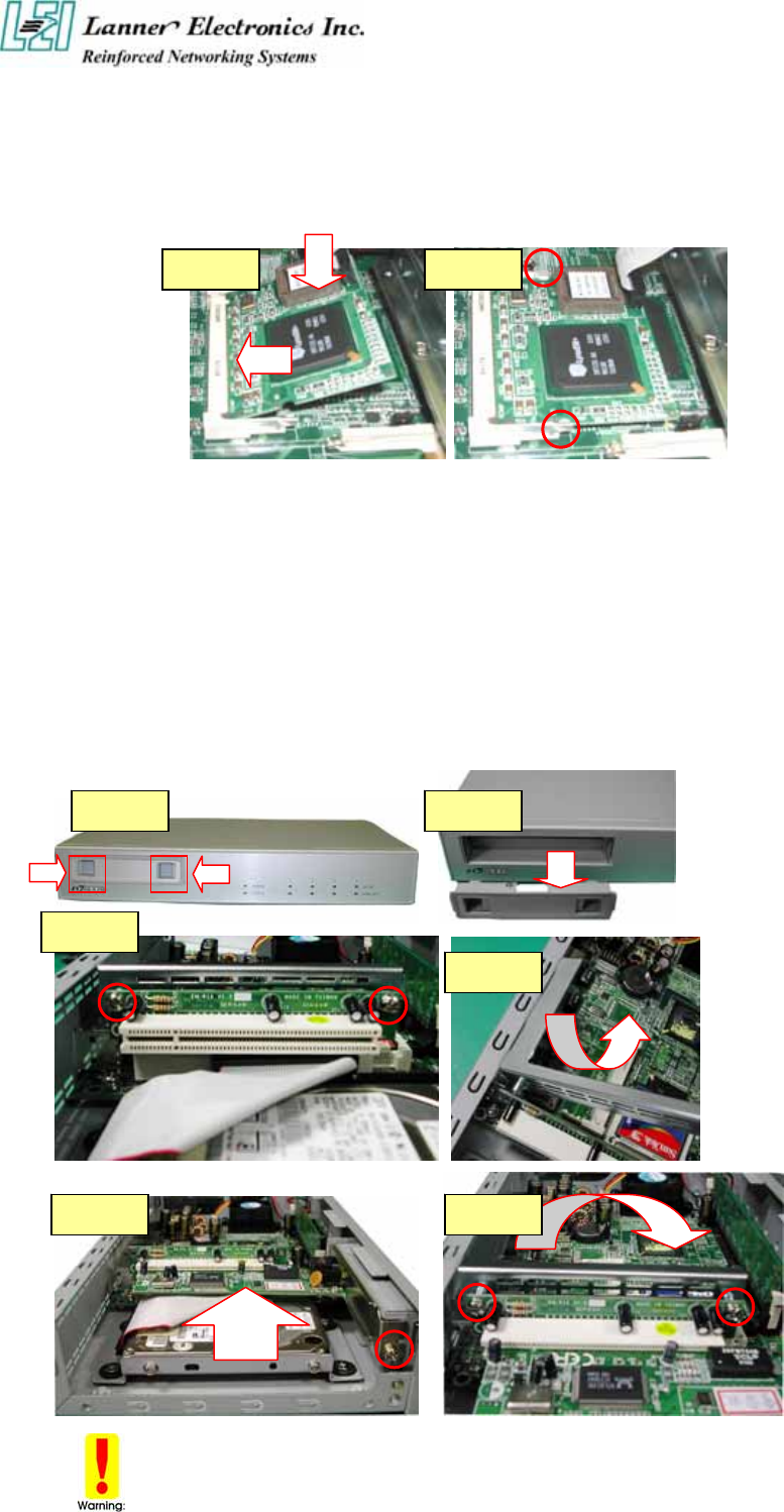
- Installing the Mini-PCI Card
Step 1: Insert the PCI expansion card into the mini-PCI slot at 45 degree.
Step 2: Push down the PCI expansion card and the PCI expansion card is clicked together
completely with the PCI expansion slot.
- Installing the Standard PCI Expansion Card
Step 1: Press the both button.
Step 2: Move the bracket.
Step 3: Take off two screws from the riser card bracket.
Step 4: Pull up the reiser card bracket.
Step 5: Insert your PCI card and screw the screw.
Step 6: Put the riser card bracket and screw the two screws.
Be notes that the power consumption of the PCI card must be under 15W.
Ste
p
1 Ste
p
2
Ste
p
1 Ste
p
2
Ste
p
3
Ste
p
4
Ste
p
5 Ste
p
6

Chapter 3
Award BIOS Setup
Award‘s ROM BIOS provides a built-in Setup program that allows users to modify the basic
system configuration and settings. The modified data will be stored in a battery-backed CMOS
RAM so that this data will be retained even when the power is turned off. In general, the
information saved in the CMOS RAM remains unchanged unless there is a configuration
change in the system, such as hard drive replacement or new equipment installment.
3.1 Running AWARD BIOS
The Setup Utility is stored in the BIOS ROM. When the power of the computer system is
turned on, a screen message will appear to give you an opportunity to call up the Setup Utility
while the BIOS will enter the Power On Self Test (POST) routines. The POST routines
perform various diagnostic checks while initializing the board hardware. If the routines
encounter an error during the tests, the error will be reported in one of two ways, a series of
short beeps or an error message on the screen. There are two kinds of errors, fatal and non-fatal.
The system can usually continue the boot up sequence with non-fatal errors. Non-fatal error
messages usually appear on the screen along with the following instructions:
“ Press <F1> to RESUME ”
Write down the message and press the F1 key to continue the boot up sequence. After the
POST routines are completed, the following message appears:
“ Press DEL to enter SETUP ”
Entering Setup
Turn on the power of the computer system and press <Del> immediately. If you don’t have the
chance to respond, reset the system by simultaneously pressing the <Ctrl>, <Alt> and <Delete>
keys, or by pushing the ‘ Reset ’ button on the system cabinet. You can also restart by turning
the system OFF then ON.
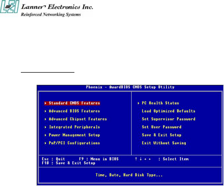
3.2 CMOS Setup Utility
To access the Award BIOS HIFLEX SETUP UTILITY program, press the <DEL> key. The
screen display will appears as:
Main Program Screen
This screen provides access to the utility‘s various functions.
Listed below are explanation of the keys displayed at the bottom of the screen:
<ESC> : Exit the utility.
<Ç È Æ Å> : Use arrow keys Ç È Æ Å to move cursor to your desired selection.
<F1> : General Help
<F5> : Previous Values
<F6> : Fail-Safe Defaults
<F7> : Optimized Defaults
<F10> : Saves all changes made to Setup and exits program.
+/-/PU/PD : Change Value

Standard CMOS Setup: Use this menu for basic system configurations.
Advanced BIOS Features: Use this menu to set the Advanced Features available on your
system.
Advanced Chipset Features: Use this menu to change the values in the chipset registers and
optimize your system’s performance.
Integrated Peripherals: Use this menu to specify your settings for integrated peripherals.
Power Management Setup: Use this menu to setup power control.
PnP/PCI Configuration: This entry appears if your system supports PnP/PCI.
PC Health Status: This entry shows your PC health status if Hardware Monitor Chipset is
installed.
Load Optimized Defaults: Use this menu to load the BIOS default values that are factory
settings for optimal performance system operations.
Set Supervisor Password: Use this menu to set Supervisor Passwords.
Set User Password: Use this menu to set User Passwords.
Save & Exit Setup: Save CMOS value changes to CMOS and exit setup.
Exit Without Saving: Abandon all CMOS value changes and exit setup.
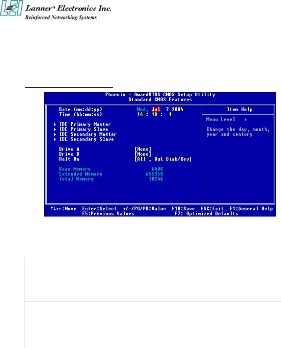
3.3 Standard CMOS Setup
When you select the “STANDARD CMOS SETUP” on the main program, the screen display
will appears as:
Standard CMOS Setup Screen
The Standard CMOS Setup utility is used to configure the following components such as date,
time, hard disk drive, floppy drive, display and memory. Once a field is highlighted, on-line
help information is displayed in the left bottom of the Menu screen.
BIOS Setting and Terms Description
Set Date Month, Date, Year.
Set Time : Hour, Minute and Second. Use 24-hour clock format (for p.m. time,
add 12 to the hour number, e.g. you would enter 4:30 p.m. as 16:30).
IDE Primary (Secondary)
Master (Slave):
Press PgUp / <+> or PgDn / <-> to select Manual, None, Auto type.
Note that the specifications of your drive must match with the drive
table. The hard disk will not work properly if you enter improper
information for this category. If your hard disk drive type is not
matched or listed, you can use Manual to define your own drive type
manually.
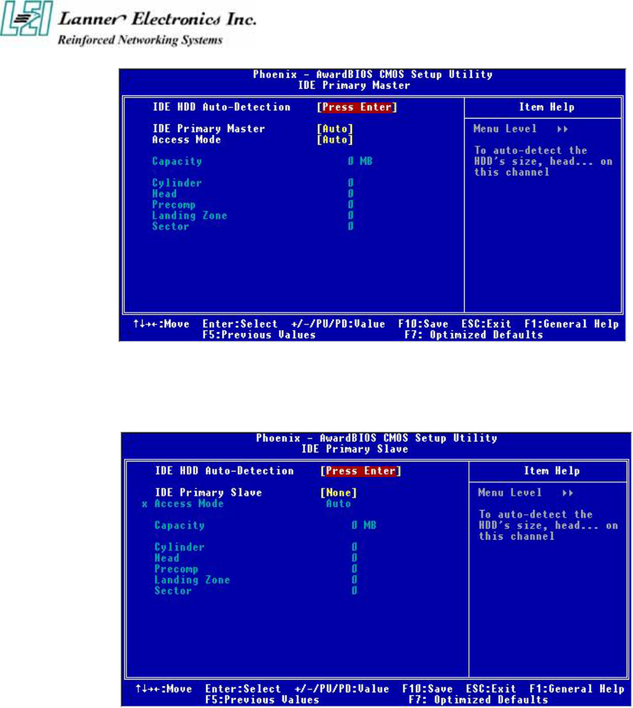
If you select Manual, related information is asked to be entered to the following items. Enter
the information directly from the keyboard. This information should be provided in the
documentation from your hard disk vendor or the system manufacturer.
IDE Primary Master
Ç È Æ Move Enter: Select +/-/PU/PD: Value F10: Save Esc: Exit F1: General Help
F5: Previous Values F6: Fail-Safe Defaults F7: Optimized Defaults
IDE Primary Slave
Ç È Æ Move Enter: Select +/-/PU/PD: Value F10: Save Esc: Exit F1: General Help
F5: Previous Values F6: Fail-Safe Defaults F7: Optimized Defaults
Here is a brief explanation of drive specifications:
z Access Mode: The settings are Auto, Normal, Large, LBA.
z Cylinder: Number of cylinders
z Head: Number of heads
z Precomp: Write precom
z Landing Zone: Landing Zone
z Sector: Number of sectors

Drive A and Drive B : Select the correct specifications for the diskette drive(s) installed in the
computer.
None No diskette drive installed
360K 5.25 in 5-1/4 inch PC-type standard drive; 360 kilobyte capacity
1.2M, 5.25 in 5-1/4 inch AT-type high-density drive; 1.2 megabyte capacity
720K 3.5 in 3 1-2 inch double-sided drive; 720 kilobyte capacity
1.44M, 3.5 in 3 1-2 inch double-sided drive; 1.44 megabyte capacity
2.88M, 3.5 in 3 1-2 inch double-sided drive; 2.88 megabyte capacity
Note : 1. Not Installed could be used as an option for diskless workstations..
2. Highlight the listing after each drive name and select the appropriate entry.
Halt On : During the power-on-self-test (POST), the computer stops if the BIOS detects a
hardware error. You can tell the BIOS to ignore certain errors POST and continue the boot-up
process. These are the selections:
No errors Whenever the BIOS detects a non-fatal error the system will not be
stopped and you will be prompted
All errors The system boot will be stopped for any error that may be detected.
All, But Keyboard The system boot will not stop for a keyboard error ; it will stop for all
Other errors.
All, But Diskette The system boot will not stop for a disk error ; it will stop for all other
E
rrors.
All, But Disk/Key The system boot will not stop for a keyboard or disk error ; it will stop
for all other errors.

3.4 Advanced BIOS Features Setup
When you select the “ADVANCED CMOS SETUP” on the main program, the screen display
will appears as:
Advanced BIOS Features Setup Screen
BIOS Setting and Terms Description
Virus Warning
The default setting of Virus Warning is “Disabled”. When it is enabled,
any attempt to write the boot sector and partition table will halt the system
and cause a warning message to appear. If this happens, you can use an
anti-virus utility on a virus free, bootable floppy diskette to reboot, to
clean and to investigate your system.
Quick Power On Self Test
The default setting is “Enabled”. This speeds up the Power On Self Test
(POST) by skipping some items that are normally checked during the full
POST. If your system is functioning normally, you can choose this
feature to speed up the booting process.
First / Second / Third /
Other Boot Device :
The BIOS attempts to load the operating system from the devices in the
sequence selected in these items. The settings are Floppy, LS/ZIP,
HDD-0/HDD-1/HDD-2/HDD-3, SCSI, CDROM, LAN, and Disabled
Swap Floppy Drive The default setting is “Default”. If the system has two floppy drives,
choose enable to assign physical drive B to logical drive A and vice-versa.
Boot Up Numlock Status The default setting is “On”. If set “Off”, the cursor controls will function
on the numeric keypad.
Security Option
This setting controls the password in the main screen. The options are
“Setup” and “System”. Select “Setup” and it will protect the Setup Utility
settings from being tampered with. Select “System” if you want to use
p
assword feature every time the system boots up. The default setting is
“Setup”. You can create your password by using the
“SUPERVISOR/USER PASSWORD” utility on the main program
screen.
PS/2 Mouse Function
Control
When this option is set Enabled, awardbios supports a PS/2 type mouse.
The settings are Enabled or Disabled. The default setting is Disabled.
System Boot Up Sequence.
HDD S.M.A.R.T.
Capability
Enable installs SMART(Self-Monitoring Analysis-Reporting
Technology), which issues a warning if an IDE failure is imminent.
Video BIOS Shadow Determines whether video BIOS will be copied to RAM. Video shadow
will increase the video speed. The default setting is “Eable”. Enable
copies Video BIOS to shadow RAM Improves performance.
C8000-CBFFF /
CC000-CFFFF /
D0000-D3FFF /
D4000-D7FFF /
D8000-DBFFF /
DC000-DFFFF Shadow
These categories determine whether option ROMs will be copied to
RAM.
Enabled optional shadow is enabled
Disabled optional shadow is disabled
Full Screen LOGO Show Show full screen logo during BIOS bootup process. Seetings : Enabled
and Disabled.
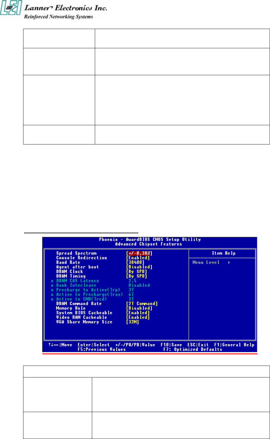
3.5 Advanced Chipset Setup
When you select the “CHIPSET FEATURES SETUP” on the main program, the screen display
will appears as:
Advanced Chipset Features Setup Screen
BIOS Setting and Terms Description
Spread Spectrum When the mainboard’s clock generator pulses, the extreme values(spikes)
of the pulses creates EMI (Electromagnetic Interference). The Spread
Spectrum function reduces the EMI generated by modulating the pulses so
that the spikes of the pulses are reduced to flatter curves.
Console Redirection Console redirection allows you to manage a host (local) system from a
client (remote) system by redirecting keyboard input and text output
through a serial port.

You can choice Enable, Disable and Auto.
Baud Rate The Default baud rate is 38400.
DRAM Clock This item enables you to manually set the DRAM Clock. We recommend
that you leave this item at the default value.
DRAM Timing Control Set this By SPD to enable the system to automatically set the SDRAM
timing by SPD (Serial Presence Detect). SPD is an EEPROM chip on the
DIMM module that stores information about the memory chips it contains,
including size, speed, voltage, row and column addresses, and
manufacturer.
DRAM CAS Latency (2.5) Enables you to select the CAS latency time in HCLKs of 2/2 or 3/3. The
value is set at the factory depending on the DRAM installed. Do not change
the val-ues in this field unless you change specifications of the installed
DRAM or the installed CPU. The options are "2" and "2.5" default.
Bank Interleave Enable this item to increase memory speed. When enabled, separate
memory banks are set for odd and even addresses and the next byte of
memory can be accessed while the current byte is being refreshed.
Precharge to Active
(3T/4T)
This item is used to designate the minimum Row Precharge time of the
SDRAM devices on the module.
Active to Precharge
(6T/10T)
This item specifies the number of clock cycles needed after a bank active
command before a precharge can occur.
Active to CMD (3T) This item specifies the minimum required delay between activation of
different rows.
DRAM DRAM Command
Rate (2T command)
This item enables you to specify the waiting time for the CPU to issue the
next command after issuing the command to the DDR memory. We
recommend that you leave this item at the default value.
Memory Hole At
15M-16M
You can reserve this area of system memory for ISA adapter ROM. When
this area is reserved, it cannot be cached. The user information of
peripherals that need to use this area of system memory usually discusses
their memory requirements.
System BIOS Cacheable Selecting “Enabled” allows caching of the system BIOS ROM at F0000h –
FFFFFh, resulting in better system performance. However, if any program
writes to this memory area, a system error may result. The settings are
“Enabled” and “Disabled”.
Video BIOS Cacheable Selecting Enabled allows caching of the video BIOS ROM at C0000h to
C7FFFh, resulting in better video performance. However, if any program
writes to this memory area, a system error may result.
VGA Share Memory Size Select VGA memory size
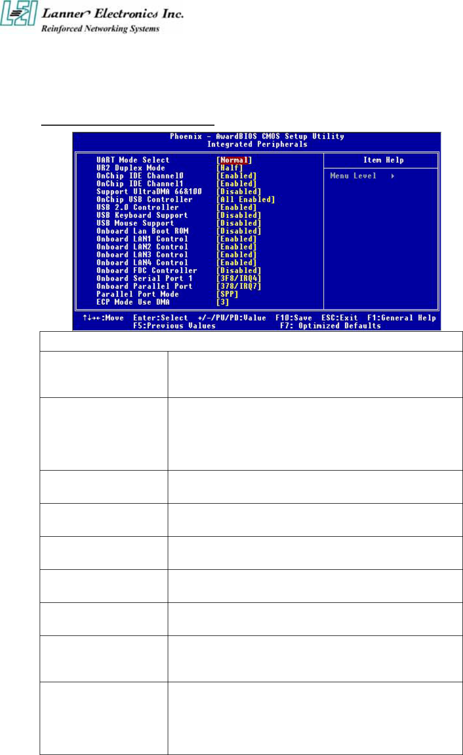
3.6 Integrated Peripherals Setup
When you select the “INTEGRATED PERIPHERIALS” on the main program, the screen
display will appears as:
Integrated Peripherals Setup Screen
BIOS Setting and Terms Description
OnChip IDE Device
The integrated peripheral controller contains an IDE interface with
support for two IDE channels. Select Enabled to activate each channel
separately.
Support UltraDMA 66&100
Ultra DMA/66&100 implementation is possible only if your IDE hard
drive supports it and the operating environment includes a DMA driver.
If your hard drive and your system software both support Ultra
DMA/66, select Auto to enable BIOS support. The settings are
“Disabled”.
OnChip USB Controller Select Enabled if your system contains a Universal Serial Bus(USB)
controller and you have USB peripherals.
USB 2.0 Controller Select Enabled if your system contains a Universal Serial Bus(USB)
controller and you have USB 2.0 peripherals.
USB Keyboard Support Select Enabled if your system contains a Universal Serial Bus(USB)
controller and you have a USB keyboard.
USB Mouse Support Select Enabled if your system contains a Universal Serial Bus(USB)
controller and you have a USB Mouse.
UART Mode Select The serial port on your system may offer a variety of infrared port
modes. Click here for a description of various modes.
UR2 Duplex Mode
This field is available when UART 2 Mode is set to either ASKIR or
IrDA. This item enables you to determine the infrared function of the
onboard infrared chip. The options are Full and Half (default).
Onboard LAN Boot ROM
PXE is based on the Dynamic Host Configuration Protocol (DHCP), and
Trivial File Transfer Protocol (TFTP). When a PXE enabled client boots,
it obtains an IP address from a DHCP server. It then discovers the Proxy
DHCP server, which provides the client with a list of Boot Servers. The
client then communicates with the appropriate Boot Server and receives
the name of the boot image. The client uses TFTP to download the
Network Bootstrap Program (NBP) from the Boot Server and then
initiates execution of the image (boots from the image).
Onboard
LAN1/LAN2/LAN3/LAN4
Control
Enable your LAN Controller
On board FDC Controller Enable the onboard floppy controller. Select Enabled when you have
installed a floppy disk drive.
Onboard Serial Port 1
Select an address and corresponding interrupt for the first and second
serial ports. The settings are “3F8/IRQ4”, “2E8/IRQ3”, “3E8/IRQ4”,
“2F8/IRQ3”, “Disabled”, “Auto”.
Onboard Parallel Port
This item allows you to determine onboard parallel port controller I/O
address setting. The settings are “378H/IRQ7”, “278H/IRQ5”,
“3BC/IRQ7”, “Disabled”.
Parallel Port Mode
Select an operating mode for the onboard parallel (printer) port. Select
“Normal”, “Compatible”, or “SPP” unless you are certain your hardware
and software both support one of the other available modes.
ECP Mode Use DMA Select a DMA channel for the parallel port for use during ECP mode.
The settings are “3” and “1”
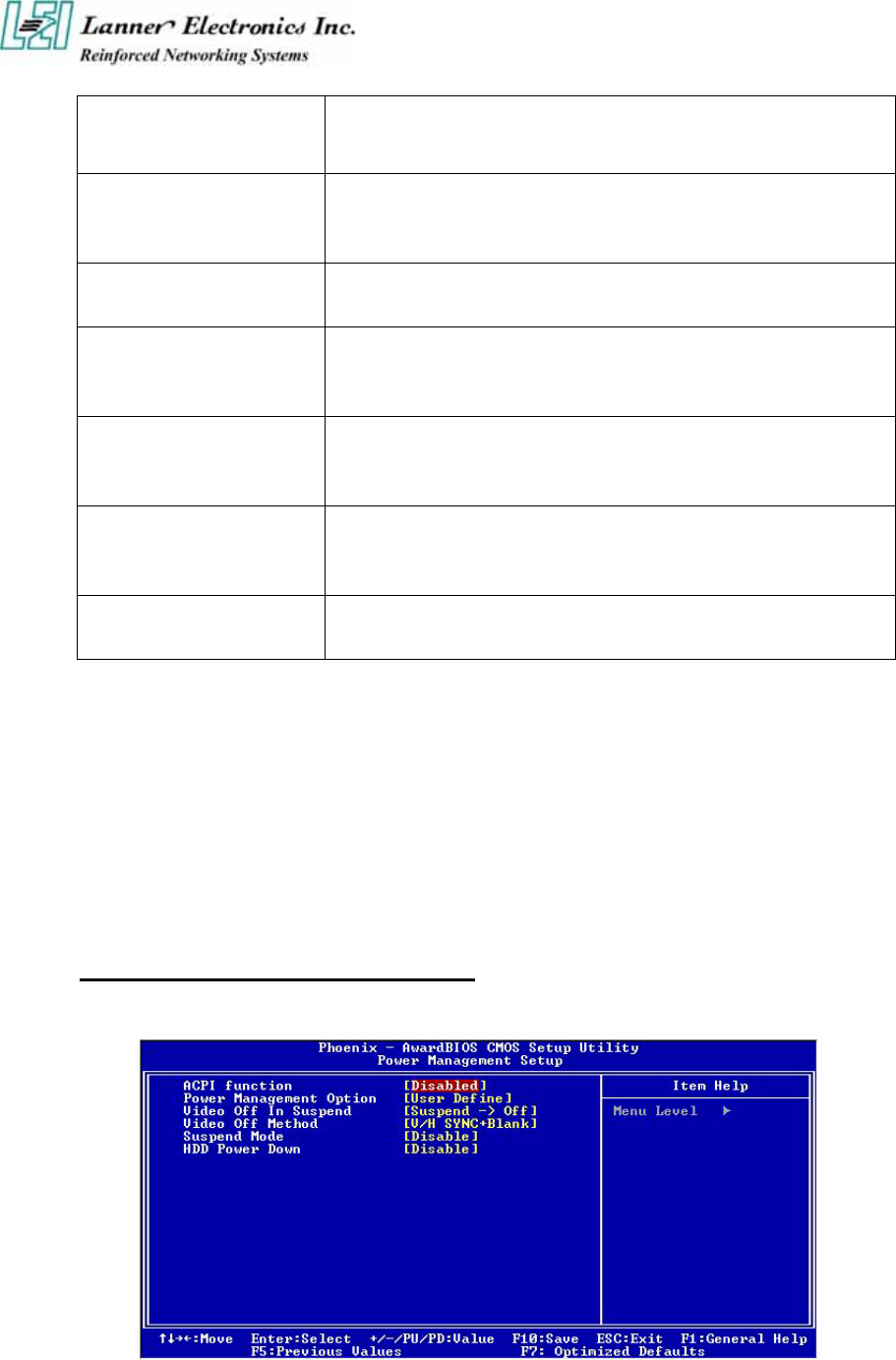
3.7 Power Management Setup
The “Power Management Setup” controls the CPU card‘s “Green” features. When you select
the “POWER MANAGEMENT SETUP” on the main program, the screen display will
appears as:
Power Management Setup Screen
ACPI Function : This item allows you to enable or disable the Advanced Configuration and
Power Management (ACPI). The settings are “Enabled” and “Disabled”.
Power Management :

There are three selections for Power Management, three of which have fixed mode setting
Disable (Default) No power management. Disables all four modes.
Min. Power Saving Minimum power management. Doze Mode=1hr. Standby Mode =1hr.,
Suspend Mode=1hr., and HDD Power Down=15min.
Max. Power Saving Maximum power management. –Only available for SL CPU’s. Doze
Mode=1min., Standby Mode=1min., Suspend Mode=1min., and HDD Power
Down=1min
User Defined Allows you to set each mode individually. When not disabled, each of the
ranges are from 1 min. to 1 hr. except for HDD Power Down which ranges
from 1 min. to 15 min. and disabled
Video Off In Suspend : This option is for choosing the setting in which the monitor will turn
off. The default setting is “Suspend”.
Always On The monitor will be turned on
Suspend -> Off The monitor will be turned off.
Video Off Method : This determines the manner in which the monitor is blanked. The default
setting is “V/H SYNC+Blank”.
V/H SYNC+Blank This selection will cause the system to turn off the vertical and
horizontal synchronization ports and write blank to the video buffer.
Blank Screen This option only writes blanks to the video buffer.
Suspend Type : Options are from “1 Min”. to “15 Min”.
HDD Power Down: Options are from “1 Min”. to “15 Min”. and “Disable”. The IDE hard
drive will spin down if it is not accessed within a specified length of time.
After you have made your selection in the POWER MANAGEMENT SETUP, press the
<ESC> key to go back to the main program screen.
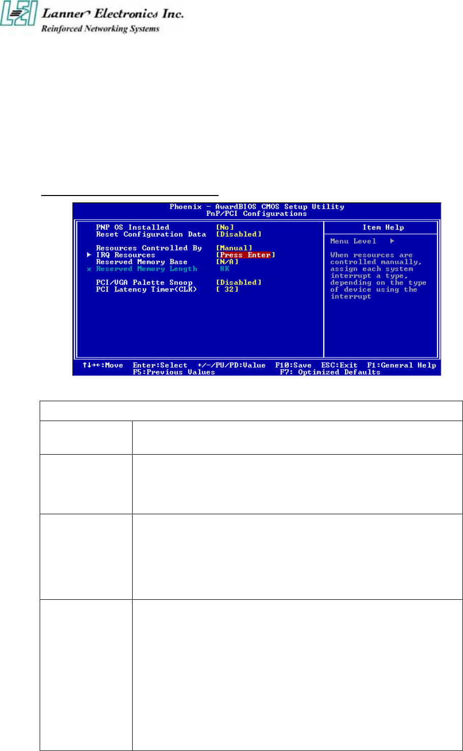
3.8 PCI Plug and Play Setup
Both the ISA and PCI buses on the CPU card use system IRQs & DMAs. You must set up the
IRQ and DMA assignments correctly through the PnP/PCI Configuration Setup utility,
otherwise the motherboard will not work properly.
PnP/PCI Configuration Setup Screen
BIOS Setting and Terms Description
PnP OS Installed Select “Yes” if you are using a Plug and Play capable operating system. Select
“NO” if you need the BIOS to configure non-boot devices
Reset Configuration
Data
N
ormally, you leave this field “Disabled”, Select “Enabled” to reset Extended
System Configuration Data (ESCD) when you exit Setup if you have installed a
new add-on and the system reconfiguration has caused such a serious conflict that
the operating system cannot boot.
Resource Controlled
By
The Award Plug and Play BIOS has the capacity to automatically configure all of
the boot and Plug and Play compatible devices. However, this capability means
absolutely nothing unless you are using a Plug and Play operating system such as
Windows®98. If you set this field to “Manual” choose specific resources by
going into each of the sub menu that follows this field ( a sub menu is proceded
by a “►”). The settings are “Auto(ESCD)”, “Manual”.
IRQ Resources
When resources are controlled manually, assign each system interrupt as one of
the following types, depending on the type of device using the interrupt.
IRQ3/4/5/7/9/10/11/12/14/15:
These items s
p
ecify the bus where the specified IRQ line is used. The settings
determine if Award BIOS should remove an IRQ from the pool of available IRQs
p
assed to devices that are configurable by the system BIOS. The available IRQ
pool is determined by reading the ESCD NVRAM. If more IRQs must be
removed from the IRQ pool, the end user can use these settings to reserve the IRQ
b
y assigning an ISA/EISA setting to it. Onboard I/O is configures by Award
BIOS. All IRQs used by onboard I/O are configured as PCI/PnP. If all IRQs are

set to ISA/EISA, and IRQ14/15 are allocated to the onboard PCI IDE, IRQ9 will
still be available for PCI and PnP devices. Settings: ISA/EISA and PCI/PnP.
Reserved Memory
Base
This option specifies the beginning address (in hex) of the reserved memory area.
The specified ROM memory area is reserved for use by legacy ISA adapter cards.
The settings are N/A, C8000, CC000, D0000, D4000, D8000 or DC000.
Reserved Memory
Length
This option specifies the size of the memory area reserved for legacy ISA adapter
cards. The settings are 8K, 16K, 32K or 64K.
PCI/VGA Palette
Snoop Leave this field at “Disabled”. The settings are “Enabled”, “Disabled”.
PCI Latency
Timer(CLK)
When enabled this item, the PCI cycle will only be deferred after it has been held
in a “Snoop Stall” for 31 clocks and another ADS# has arrived. When disabled,
the PCI cycle will be deferred immediately after the GMCH receives another
ADS#.
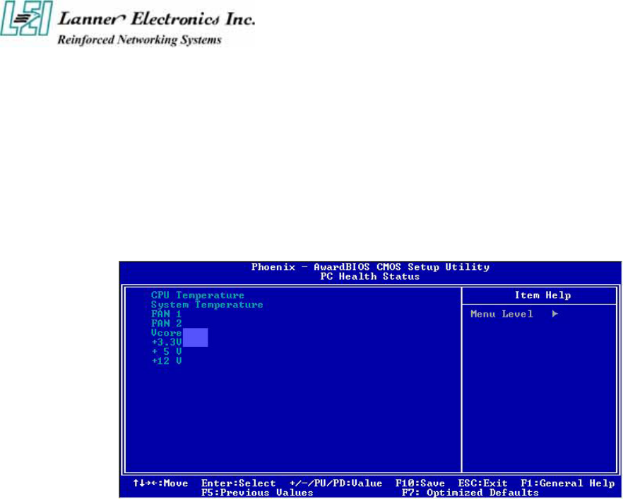
3.9 PC Health Status
This section helps you to get more information about your system including CPU temperature,
FAN speed and voltages. It is recommended that you contact your motherboard supplier to get
proper value about your setting of the CPU temperature.
Ç È Æ Move Enter: Select +/-/PU/PD: Value F10: Save Esc: Exit F1: General Help
F5: Previous Values F6: Fail-Safe Defaults F7: Optimized Defaults
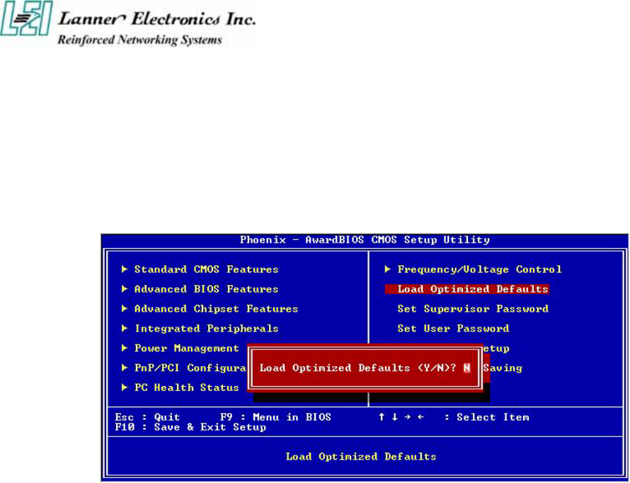
3.10 Load Optimal Defaults
When you press “Enter” on this item, you get a confirmation dialog box with a message similar
to :
Pressing “Y” loads the default values that are factory settings for optimal performance system
operations.
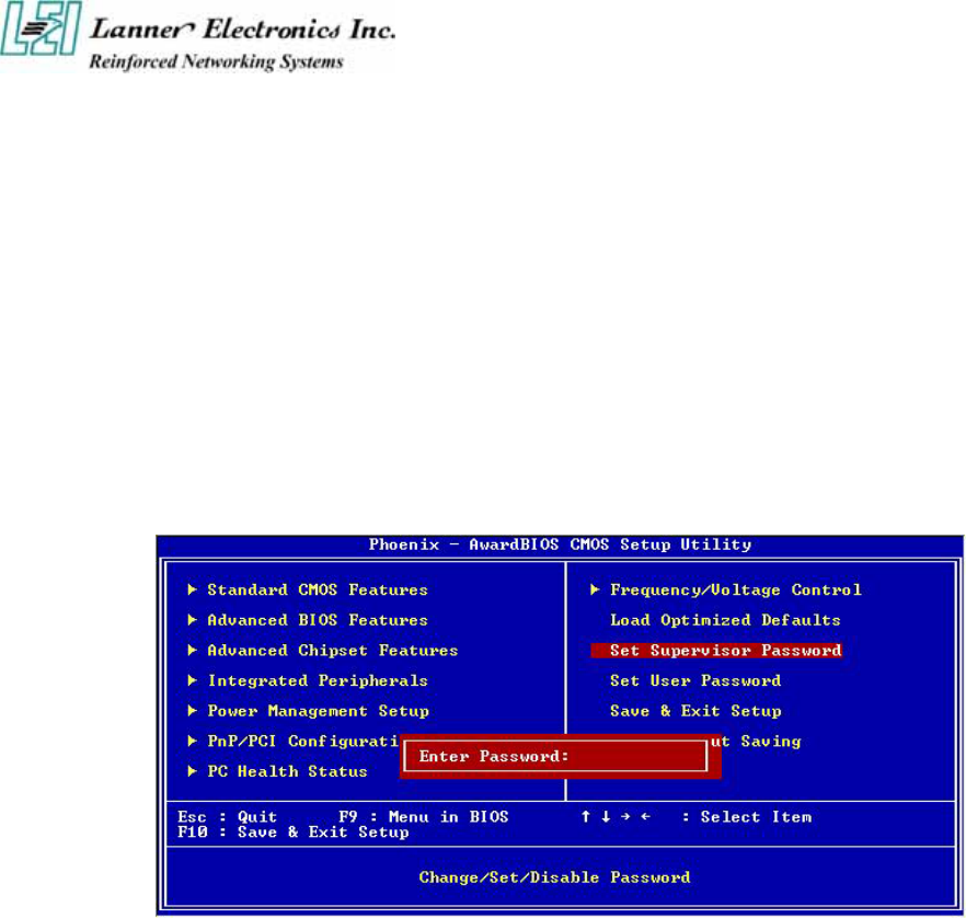
3.11 Supervisor / User Password
The “SUPERVISOR/USER PASSWORD” utility sets the password. The SBC is shipped with
the password disabled. If you want to change the password, you must first enter the current
password, then at the prompt -- enter your new password. The password is case sensitive, and
can be up to 8 alphanumeric characters. Press <Enter> after you have finished typing in the
password. At the next prompt, confirm the new password by re-typing it and pressing <Enter>
again. When you are done, the screen automatically reverts to the main screen. Remember that
when you use this feature, the “Security Option” line in BIOS FEATURES SETUP will
determine when entering the password will be required.
To disable the password, press the <Enter> key instead of entering a new password when the
“Enter Password” in the dialog box appears. A message will appear confirming that the
password is disabled.
If you have set both supervisor and user password, only the supervisor password allows you to
enter the BIOS SETUP PROGRAM.
Note : If you forget your password, the only way to solve this problem is to discharge the
CMOS memory.
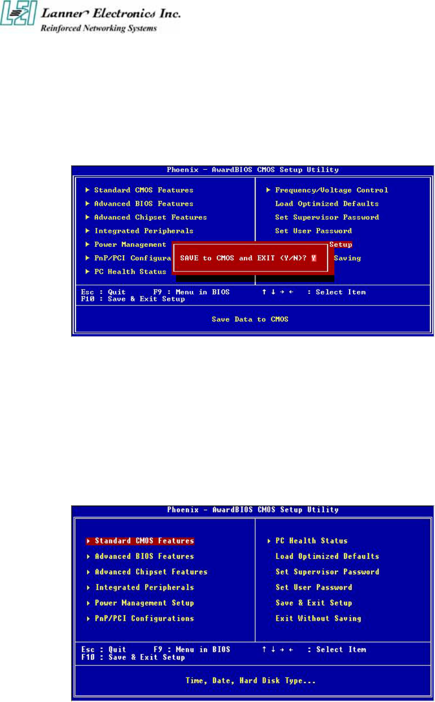
3.12 Save & Exit Setup
Select this option and press the <Enter> key to save the new setting information in the CMOS
memory and continue with the booting process.
Typing Y will allow you to quit the Setup Utility and save the user setup changes to RTC
CMOS.
Typing N will return to Setup Utility.
3.13 Exit Without Saving
Select this option and press the <Enter > key to exit the Setup Utility without recording any
new values or changing old ones.
Typing Y will allow you to quit the Setup Utility without saving any changes to RTC CMOS.
Typing N will return to the Setup Utility.
Appendix A
Power Adapter
Power Adapter Specification
General Specifications
Input voltage 90VAC to 264 VAC
Input frequency 47 Hz to 63 Hz
Inrush current 1.2 A rms max at AC low line input and DC output full load
Input protection 2A Fuse
Input surge current 45A/60A max
Efficiency 75% min
Hold up time 10ms min, at AC nominal input/output full load
Load Regulation +/- 5%
Operating temperature 0 oC to 40 oC convection
Storage temperature -20 oC to +85 oC
EMC EN55022 “B”, FCC”B”
CE spec EN55022, EN6100-3-2, EN6100-3-3, EN50082-1,
EN6100-4-2, EN6100-4-3, EN6100-4-4
Safety approval CUL, CB, TUV, PSE-MARK, CNS
Mechanical Dimensions 118.0mm X 60.0mm X 39.0mm
Output Specifications
Loading(A) Tolerance Range
Voltage
Min Normal Max Total Regulation
Adjustable voltage
Range
+12V 0 5A +/- 5% NONE

A p p e n d i x B
Console Redirection
Console redirection allows you to maintain a system from a remote location by re-directing keyboard
input and text output through the serial port. This section will tell you how to use console redirection.
1. Please insert console cable between on FW-6420 and Remote Client System.
2. Setup BIOS in FW-6420.
BIOS Æ Advanced Chipset Setup Æ Baud Rate : 38400 (Default)
BIOS Æ Advanced Chipset Setup Æ Console Redirection : Enabled(Default)
Enabled Attempt to redirect console via COM port.
Disabled Attempt to redirect console when keyboard absent.
Auto
If keyboard is plug in the Controller board, the Console Redirection
will not display BIOS screen on remote client.
If keyboard is not plug in the Controller board, the Console
Redirection will display BIOS screen on remote client.
3. Configure Console redirection on client system. This example is for Windows platform.
i . Click the Start button, point to programs Æ Accessories Æ Communications, and click Hyper
Terminal.
ii. Enter any name for the new connection and select any icon.
iii. Click OK.
iv. From the Connect to pull-down menu, select a COM port available on your client system and
click OK.
v. Select Baud Rate Æ 38400 , Flow control ÆNone , Data bitÆ8 , Parity check Æ None , Stop
bit Æ 1.
4. Power on FW-6420 and it will display the bios information on the client system.

Terms and Conditions
Date:2004.07.08
Warranty Policy
1. All products are warranted against defects in materials and workmanship for a period of two years from the
date of your purchase.
2. The buyer will bear the return freight charges for goods returned for repair within the warranty period;
whereas manufacturer will bear the after service freight charges back to user site.
3. The buyer will pay for repair (for replaced components plus service time) and transportation charges (both
ways) for items after the expiration of the warranty period.
4. If the RMA Service Request Form does not meet the stated requirement as listed on “RMA Service“, RMA
goods will be returned at customer’s expense.
5. The following conditions resulting to the defective goods are excluded from this warranty:
A. Improper or inadequate maintenance by the customer
B. Unauthorized modification, misuse, or reversed engineering of the product
C. Operation outside of the environmental specifications for the product.
RMA Service
1. Requesting for a RMA#:
To obtain a RMA number, simply fill out and fax the “RMA Request Form” to your supplier.
2. Shipping:
A. The customer is required to fill up the problem code as listed. If your problem is not among the codes
listed, please write the symptom description on the remark.
B. Ship the defective unit(s) on freight prepaid terms.
C. Mark the RMA # clearly on the box.
D. Customer is responsible for shipping damage(s) resulting from inadequate/loose packing of the
defective unit(s).
E. Use the original packing materials whenever possible.
3. All RMA# are valid for 30 days only:
RMA goods received after the effective RMA# period will be rejected.

RMA Service Request Form
When requesting RMA service, please fill out this RMA Service Request Form.
Without this form your RMA will be REJECTED!!!
RMA No: Reasons to Return: □ Repair(Please include failure details) □ Testing Purpose
Company: Contact Person:
Phone No. Purchased Date:
Fax No.: Applied Date:
Return Shipping Address:
Shipping by: □ Air Freight □ Sea □ Express □ Others:
Item Model Name Serial Number Configuration
Item Problem Code Failure Status
*Problem Code:
01:D.O.A.
02: Second Time R.M.A.
03: CMOS Data Lost
04: FDC Fail
05: HDC Fail
06: Bad Slot
07: BIOS Problem
08: Keyboard Controller Fail
09: Cache RMA Problem
10: Memory Socket Bad
11: Hang Up Software
12: Out Look Damage
13: SCSI
14: LPT Port
15: PS2
16: LAN
17: COM Port
18: Watchdog Timer
19: DIO
20: Buzzer
21: Shut Down
22: Panel Fail
23: CRT Fail
24: Others (Pls
specify)
Request Party
Confirmed By Supplier
Authorized Signatures / Date Authorized Signatures / Date
PEXNSD01-040709
Version 1.0
Printed and published in Taiwan
