Lantronix Tsc 4092A Irig B Users Manual 4091A Operations And Maintenance
4092A IRIG-B to the manual 583cc284-a364-4a00-90c7-0a1cfeb068cc
2015-02-09
: Lantronix Lantronix-Tsc-4092A-Irig-B-Users-Manual-570341 lantronix-tsc-4092a-irig-b-users-manual-570341 lantronix pdf
Open the PDF directly: View PDF ![]() .
.
Page Count: 34

TSC 4092A IRIG-B Autosense
Fault Switch
Operations and Maintenance
Manual
4775 Walnut Street
Suite 1B
Boulder, CO 80301
www.timing.com
Phone: (303) 939-8481

TSC 4092A IRIG-B Autosense Fault Switch Operations and Maintenance Manual
Copyright © 2005 Timing Solutions Corporation
Timing Solutions is a trademark of the Timing Solutions Corporation.
Other product and company names may be trademarks of their respective owners.
DOC04092A Rev A
Revision History
Revision Description Date Approved
A Initial release. 5/8/05 TLE

4092A Operations and Maintenance Manual i
Contents
1: Introduction 1
1.1 Symbols . . . . . . . . . . . . . . . . . . . . . . . . . . . . . . . . . . . . . . . . . . . . . . . . . . . . . . . . . . . . . . . . . . . 1
1.2 About This Manual . . . . . . . . . . . . . . . . . . . . . . . . . . . . . . . . . . . . . . . . . . . . . . . . . . . . . . . . . . 2
1.2.1 Conventions . . . . . . . . . . . . . . . . . . . . . . . . . . . . . . . . . . . . . . . . . . . . . . . . . . . . . . . . . . . 2
1.3 4092A Overview . . . . . . . . . . . . . . . . . . . . . . . . . . . . . . . . . . . . . . . . . . . . . . . . . . . . . . . . . . . . 3
2: Installing and Setting Up the 4092A 5
2.1 Safety Information . . . . . . . . . . . . . . . . . . . . . . . . . . . . . . . . . . . . . . . . . . . . . . . . . . . . . . . . . . . 5
2.2 Installing the 4092A. . . . . . . . . . . . . . . . . . . . . . . . . . . . . . . . . . . . . . . . . . . . . . . . . . . . . . . . . . 5
2.3 Assigning a Static IP Address . . . . . . . . . . . . . . . . . . . . . . . . . . . . . . . . . . . . . . . . . . . . . . . . . . 6
2.4 Selecting the Active Input Channel . . . . . . . . . . . . . . . . . . . . . . . . . . . . . . . . . . . . . . . . . . . . . . 8
2.5 Setting the 4092A to Autoswitch Mode . . . . . . . . . . . . . . . . . . . . . . . . . . . . . . . . . . . . . . . . . . 9
2.6 Cleaning. . . . . . . . . . . . . . . . . . . . . . . . . . . . . . . . . . . . . . . . . . . . . . . . . . . . . . . . . . . . . . . . . . . 9
3: Monitoring the 4092A 11
3.1 Accessing the System . . . . . . . . . . . . . . . . . . . . . . . . . . . . . . . . . . . . . . . . . . . . . . . . . . . . . . . 11
3.2 Checking System Information . . . . . . . . . . . . . . . . . . . . . . . . . . . . . . . . . . . . . . . . . . . . . . . . . 11
3.2.1 Checking Status and Alarms . . . . . . . . . . . . . . . . . . . . . . . . . . . . . . . . . . . . . . . . . . . . . 11
3.2.2 Checking Model Number and Software Version . . . . . . . . . . . . . . . . . . . . . . . . . . . . . . 14
3.3 Understanding Alarm Output. . . . . . . . . . . . . . . . . . . . . . . . . . . . . . . . . . . . . . . . . . . . . . . . . . 15
4: Troubleshooting the 4092A 17
4.1 Troubleshooting Input Problems . . . . . . . . . . . . . . . . . . . . . . . . . . . . . . . . . . . . . . . . . . . . . . . 17
4.2 Troubleshooting Output Problems. . . . . . . . . . . . . . . . . . . . . . . . . . . . . . . . . . . . . . . . . . . . . . 18
4.3 Troubleshooting Power Supply Problems . . . . . . . . . . . . . . . . . . . . . . . . . . . . . . . . . . . . . . . . 18
4.4 Configuring for Input Signal and Impedance . . . . . . . . . . . . . . . . . . . . . . . . . . . . . . . . . . . . . 19
4.5 Configuring for Dual Power Supplies . . . . . . . . . . . . . . . . . . . . . . . . . . . . . . . . . . . . . . . . . . . 19
4.6 Replacing Power Supplies . . . . . . . . . . . . . . . . . . . . . . . . . . . . . . . . . . . . . . . . . . . . . . . . . . . . 20
4.7 Replacing Fuses. . . . . . . . . . . . . . . . . . . . . . . . . . . . . . . . . . . . . . . . . . . . . . . . . . . . . . . . . . . . 21
4.8 Verifying Operational Problems . . . . . . . . . . . . . . . . . . . . . . . . . . . . . . . . . . . . . . . . . . . . . . . 21
5: Warranty and Shipping Information 23
5.1 Warranty Information . . . . . . . . . . . . . . . . . . . . . . . . . . . . . . . . . . . . . . . . . . . . . . . . . . . . . . . 23
5.2 Shipping Information. . . . . . . . . . . . . . . . . . . . . . . . . . . . . . . . . . . . . . . . . . . . . . . . . . . . . . . . 23
5.2.1 Packing Instructions. . . . . . . . . . . . . . . . . . . . . . . . . . . . . . . . . . . . . . . . . . . . . . . . . . . . 23
A Specifications 25
ii
A.3 Electrical Specifications . . . . . . . . . . . . . . . . . . . . . . . . . . . . . . . . . . . . . . . . . . . . . . . . . . . . . 25
A.3.1 Environment Specifications. . . . . . . . . . . . . . . . . . . . . . . . . . . . . . . . . . . . . . . . . . . . . . 26
A.4 Physical Specifications . . . . . . . . . . . . . . . . . . . . . . . . . . . . . . . . . . . . . . . . . . . . . . . . . . . . . . 26
Glossary 27
Index 29
4092A Operations and Maintenance Manual 1
1: Introduction
Note
FIRST READ THIS MANUAL THOROUGHLY.
This is especially true for the sections regarding Safety and Operation.
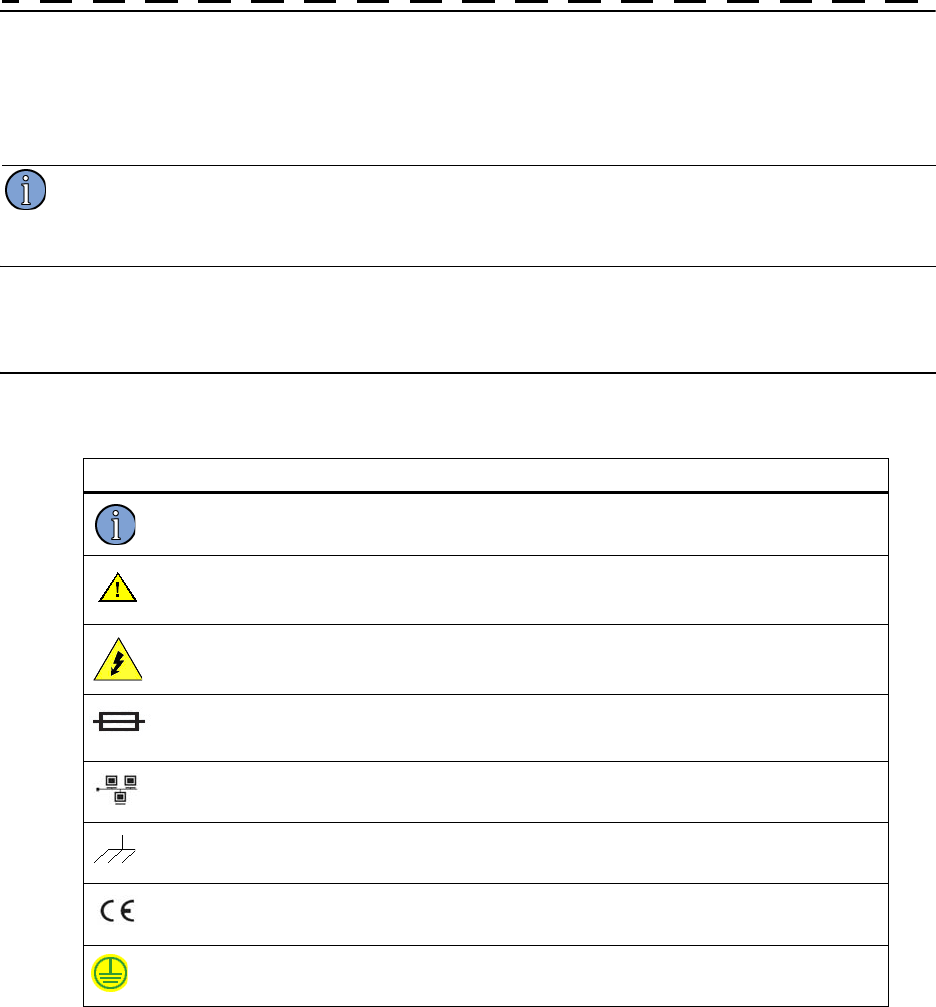
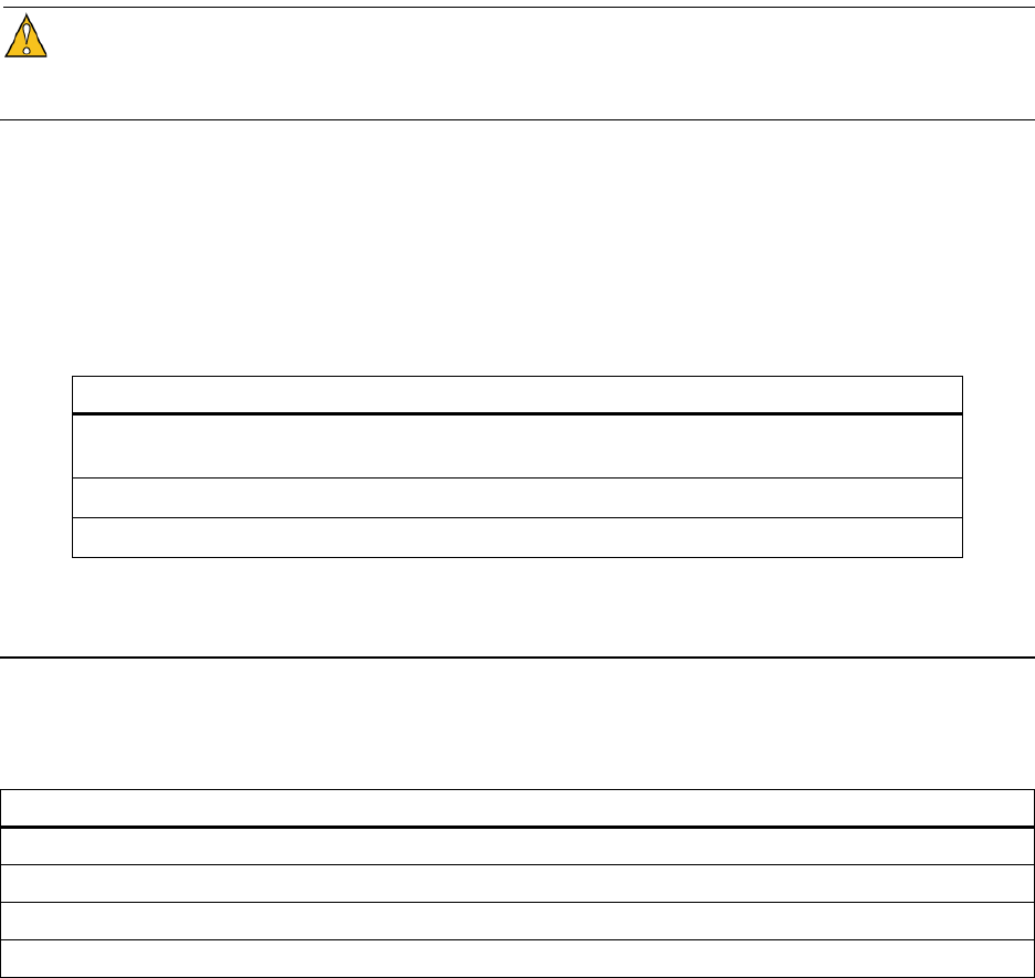
1.1 Symbols
These symbols (icons) appear throughout the manual as well as on the unit itself.
Symbol Definition
Note This symbol means the following information is a note that gives you important
information that may affect how you use the 4092A.
Caution, refer to manual. Read all instructions in this manual before using this
product.
Caution - Risk of electrical shock
Fuse symbol.
LAN port, network. DO NOT CONNECT TO TELECOM CONNECTIONS
THAT CARRY HAZARDOUS VOLTAGES.
Chassis ground.
CE marking attesting compliance with applicable European Directives.
Earth terminal symbol: used to indicate an earth ground connection to chassis.
21: Introduction
1.2 About This Manual
This manual tells you how to install, set up, monitor, and troubleshoot the 4092A.
“Chapter 1, Introduction” on page 1 explains symbols that appear in the manual and on the unit as
well as documentation conventions. The chapter also briefly describes the 4092A.
“Chapter 2, Installing and Setting Up the 4092A” on page 5 contains important safety information
and describes how to install the 4092A, assign a fixed IP address, select the active channel, and set
the autoswitching mode.
“Chapter 3, Monitoring the 4092A” on page 11 describes how to check status and monitor alarms.
“Chapter 4, Troubleshooting the 4092A” on page 17 describes how to troubleshoot the inputs and
outputs, replace power supplies, and replace fuses.
“Chapter 5, Warranty and Shipping Information” on page 23 explains how to contact Timing
Solutions Corporation for warranty service and provides shipping guidelines.
“Appendix A, Specifications” on page 25 contains the detailed specifications for the 4092A.
1.2.1 Conventions
This manual uses several typographical conventions to help explain how to use the 4092A.
Convention Definition
Bold Words in bold show:
Buttons and icons to click
Menu options to select
Commands to type
Non-variable information displayed in response to commands
Italics Words in italics show:
Names of windows and dialog boxes
Variable information displayed in response to commands
4092A Operations and Maintenance Manual 3
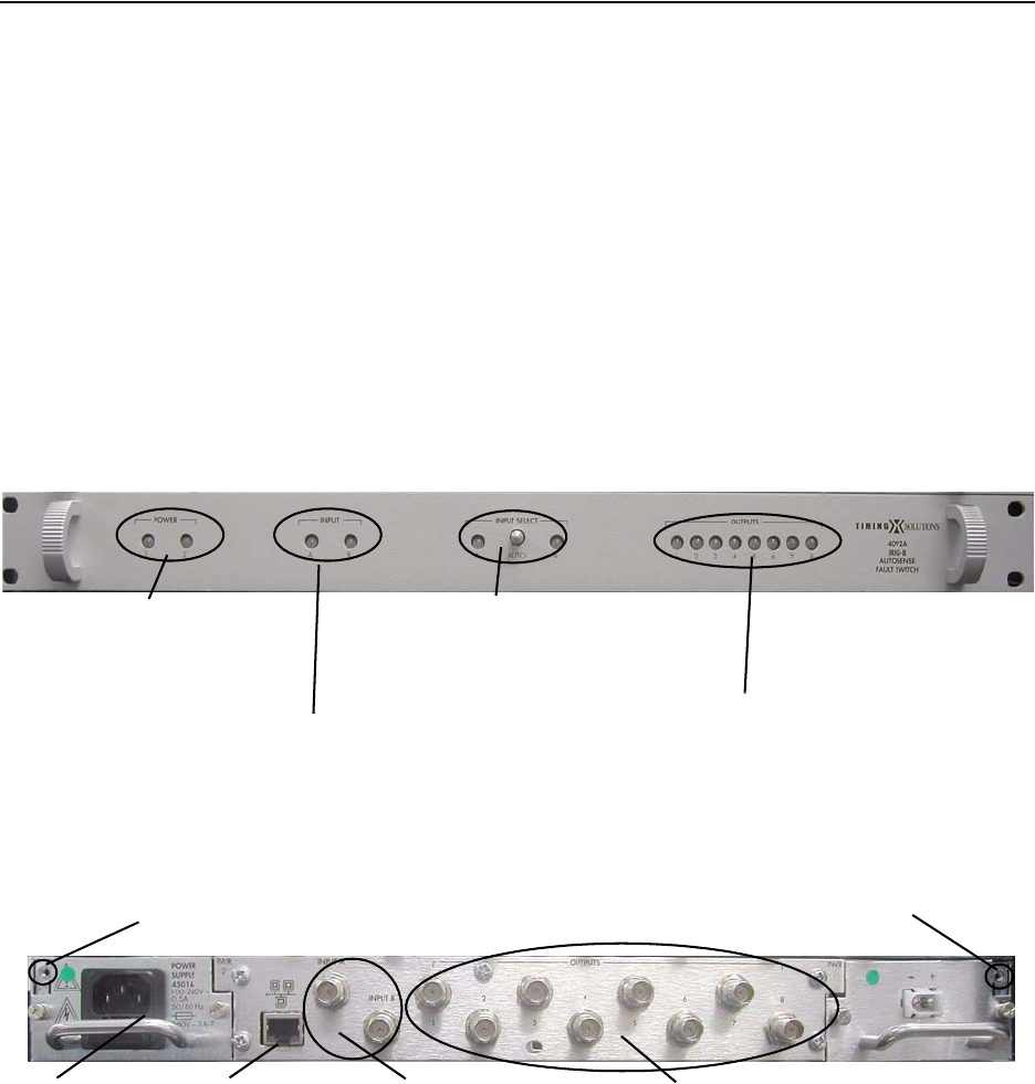
1.3 4092A Overview
The TSC 4092A IRIG-B Autosense Fault Switch is a 1U (1.75") high, 19-inch, rack-mount,
autosense, fault switch that accepts two IRIG-B inputs and produces eight outputs (chosen from
the two inputs). The unit can be configured with redundant hot swappable AC or DC power
supplies. The TSC 4092A can also be configured to accept two 1-200 kHz sinewave signals but
traditionally would be used as an IRIG-B Fault Switch.
The front panel provides green/red LED status for the inputs and for all output signals, as well as
indicating the active input signal. A green/red LED on the front panel also provides power status.
The front panel also has a locking toggle control switch that you can use to manually switch
between input signals or to configure the unit to switch automatically upon input signal failure.
An Ethernet port on the rear panel provides the capability to remotely monitor the status of the
power supplies, input, and all output signals. Any failure in the unit will immediately provide an
alarm to this port.
Figure 1 shows the 4092A’s front panel, and Figure 2 shows the 4092A’s rear panel.
Figure 1: Front panel
Figure 2: Rear panel
INPUT SELECT–Lit LED shows active
input. Use toggle switch to select active
input and set autoswitch mode.
INPUT–Green when connected to
input and receiving a signal. Red when
not receiving an input signal.
OUTPUT STATUS–Green during normal
operation of output signals. All red when
unit has no input signal on the active
channel.
POWER–Green when power is
on. One unlit LED shows unit has
one power supply. Red shows a
power supply failure.
INPUT A and B–Connect
IRIG-B or 1 kHz - 200 kHz
sinewave.
OUTPUTS–8 BNC
connectors.
Chassis ground
connection point.
AC POWER–
connector.
Chassis ground
connection point.
ETHERNET
PORT–1 RJ-45
connector.
41: Introduction

4092A Operations and Maintenance Manual 5
2: Installing and Setting Up the 4092A
2.1 Safety Information
Warning
This unit is for INDOOR USE ONLY. It is not sealed to prevent moisture from entering the
enclosure.
Do not attempt to install or operate this equipment if you have not first acquired proper training.
Equipment is intended for installation in an enclosed- or open-type equipment rack.
Ensure that all cables are properly connected. The power cord must be easy to remove from the
back.
Verify that input line voltage and current capacity are within specifications before turning on the
unit.
Disconnect all sources of input power before removing the top cover of this unit.
Operating and maintenance personnel must receive proper training before installing or maintaining
electrical equipment.
2.2 Installing the 4092A
The 4092A ships ready for installation into a standard 19" (48.3 cm) rack. You can mount the unit
using General Devices slides with part numbers C-300-S-126, -128 and -130.
Required for installation:
North American or European IEC power cord. One or the other will be supplied with the
unit.
#1 Phillips screwdriver.
One #6-32 x 5/8" pan head screw with lock washer.
Customer-supplied, double-shielded RG223 cables with BNC connectors from source and
to next devices in system.
Customer-supplied, shielded LAN cable for network connection (RJ-45).
Rack-mount slide kit from General Devices, C-300-S-126, -128 or -130 (Optional)
6 2: Installing and Setting Up the 4092A
Rack mounting screws.
Screwdriver for the rack mount screws and slide, as needed.
Caution
Since the unit does not have a AC mains power switch, both the appliance inlet connector and the
plug on the detachable power supply cord are considered to be suitable disconnect means for
disconnecting the unit from the AC mains supply. If the rear of the unit is not accessible after
installation in the instrument rack, you must provide a suitable external AC disconnect means for
the unit.
To set up the 4092A:
1. Unpack carefully and inspect the 4092A.
2. Check for physical damage.
If you observe physical damage, immediately contact Timing Solutions and the
carrier.
We recommend saving the shipping container for submitting any necessary claims to
the carrier.
3. Using a #1 Phillips screwdriver and a #6-32 pan head screw, connect a safety ground wire
to the safety ground point next to one power supply.
4. Plug the female end of the power cord into the male IEC-320 plug on the rear of each
power supply.
5. Plug the male end of each power cord into a 100–240 VAC, 50/60 Hz power source.
Caution
Ensure that this power supply cord is connected to a properly grounded mains
receptacle.
6. Connect the input signal cables from the desired signal source to the INPUT A and INPUT
B BNC connectors on the rear panel.
7. Connect up to eight cables to the OUTPUT BNC connectors on the rear panel to supply
users with a copy of the input signal.
8. (Optional.) Connect a shielded LAN cable to the Ethernet port on the rear panel of the
4092A.
For information about configuring the network connection, see “2.3 Assigning a Static
IP Address” on page 6.
2.3 Assigning a Static IP Address
The 4092A contains a Lantronix® Xport™ Ethernet to RS-232 converter, which provides the
4092A’s Ethernet connection.
The 4092A ships from the factory with a default IP address of 0.0.0.0, which enables DHCP. If the
network has a DHCP server, it will assign each unit an IP address, gateway address, and subnet
mask when the unit starts up.
4092A Operations and Maintenance Manual 7
To monitor multiple 4092A units remotely through their Ethernet connections, you must assign
each unit a fixed IP address. You identify which unit is the source of an alarm by its IP address.
Follow the instructions in this section to assign a unit’s IP address.
Note
For more detailed information, see the Xport User Manual. Section 3.3 discusses several different
ways that you can assign IP addresses. Chapter 4 explains how to permanently configure the IP
address. You can download the Xport User Manual from the Lantronix® Web site as an Adobe®
Acrobat® PDF file. Go to:
http://www.lantronix.com/
If you want to permanently configure the IP address, you must install the Lantronix
DeviceInstaller software. This software is available only by downloading from the Lantronix Web
site. Go to: http://www.lantronix.com
You can also assign the IP address using Telnet.
Note
If you move the 4092A to a different network hub after setting up the static IP address, the host
computer may not be able to make a connection. You may need to release the IP address lease on
your operating system.
To assign the static IP address using the Lantronix DeviceInstaller software:
1. Obtain the following network information from your system administrator for each 4092A
you want to install:
IP Address: ______ ______ ______ ______
Subnet Mask: ______ ______ ______ ______
Gateway: ______ ______ ______ ______
2. Connect a Windows® PC to the same local subnet as the 4092A.
3. Install and start the Lantronix® DeviceInstaller software.
4. Click the Search Network icon and search for XPORT devices connected to the network,
then click Save and Exit.
5. Click the IP icon or select Assign IP Address on the Tools menu.
The hardware device number and IP address appear in the Assign IP Address dialog
box.
6. Type the new IP address and click OK.
The new IP address appears in the Lantronix DeviceInstaller window.
7. Test the IP address by pinging the 4092A’s Xport on the Lantronix Xport Installer
window.
Click the Ping icon or select Ping Device on the Tools menu.
The Ping Device window should show the IP address of the 4092A’s Xport device,
and it should show successful replies if the IP address has been configured correctly.
8. Exit the browser.

8 2: Installing and Setting Up the 4092A
To assign the static IP address using Telnet:
1. Telnet to the assigned address, port 9999.
2. Press Enter within five seconds to enter the setup mode.
3. Select Option 0.
4. Set the IP address and follow the on-screen instructions to save the setting.
5. Telnet to the new IP address.
6. Type I
You do not need to type a carriage return or line feed.
The system returns I4092A-00\r\n, where the 00 is the hardware version, and turns on
the front panel input LEDs for two seconds before returning to normal operation.
If you see these responses, you know you are communicating with the unit.
2.4 Selecting the Active Input Channel
You can select the active input channel using either the toggle switch on the front panel or
remotely using the Ethernet connection.
To select the active input channel from the front panel:
1. Move the toggle switch by pulling the switch out, then moving it to the channel you want
to use.
The LED for the selected channel should be solid green.
2. If you want the unit to automatically switch to the other input channel in the event of a
failure, move the toggle switch back to the center position.
This puts the unit into autoswitch mode.
To select the active input channel remotely:
1. Telnet to the 4092A’s IP address.
No prompt displays in the Telnet window.
2. Type either A or B, depending on which channel you want to select.
You do not need to type a carriage return or line feed.
The LED on the for the selected channel flashes green, showing that the channel has
been selected remotely. It continues to flash green until you select the channel using
the toggle switch on the front panel or set the unit to autoswitch mode.
3. If you want the unit to automatically switch to the other input channel in the event of a
failure, type: C
The LED for the selected channel changes to solid green, showing that the channel is
active and the unit is in autoswitch mode.
4092A Operations and Maintenance Manual 9
2.5 Setting the 4092A to Autoswitch Mode
As long as the 4092A is in autoswitch mode and has two input signals connected, the unit will
automatically switch to the other input channel if it stops receiving a signal on the active channel.
You can set the 4092A to autoswitch mode using either the switch on the front panel or remotely
using the Ethernet connection.
To set the 4092A to autoswitch mode from the front panel:
Move the toggle switch to the center position.
To set the 4092A to autoswitch mode remotely:
Note
The toggle switch on the front panel must be in the center position for this command to work
properly.
1. Telnet to the 4092A’s IP address.
No prompt displays in the Telnet window.
2. Type: C
2.6 Cleaning
Warning
Do not spray or use too much liquid when cleaning the unit. Liquid can enter the unit and damage
sensitive electronic components.
Clean the main chassis with a soft cloth dampened with a mild soap and water solution.
10 2: Installing and Setting Up the 4092A

4092A Operations and Maintenance Manual 11
3: Monitoring the 4092A
3.1 Accessing the System
You access the 4092A system remotely by connecting to its Command-And-Response (CNR) Port
through the Ethernet connection. The CNR port (Port 10001), which uses TCP/IP, lets you input
commands, displays results of the commands, and publishes alarms as they occur.
When you Telnet to the CNR port, the system does not display a prompt.
3.2 Checking System Information
3.2.1 Checking Status and Alarms
The system can report status and alarms that occurred since the last status check.
To check system status:
Type: S
You do not need to type a carriage return or line feed.
The system returns Sabcde,fghij\r\n where
abcde is current status.
fghij is latched alarms and changed status since the last status request.
Both abcde and fghij are hexadecimal numbers, with each bit position representing one
output. LSB (farthest right) is output 1. MSB is the input. Bits 0–12 are latched alarms.
Bits 13–19 are change in status bits.
Latched alarms remain active in the current status field and latched status field until the
problem is corrected. Changed status bits are cleared upon next status request.
Example: S0A001,00001
This example shows that input B was selected using the front panel toggle switch, channel B is
active, and output 1 had a failure since the last status request.

12 3: Monitoring the 4092A
Table 1 defines each status or alarm bit position.
Table 1: Status or alarm binary codes
Status or alarm
character
position
Bit position Bit value and description
a or f 19 Not used
18 Not used
16 and 17 Remote control bits:
0:0 = Autoswitch/don’t care
0:1 = Channel A selected
1:0 = Channel B selected
1:1 = Not used
b or g 15 and 14 Front panel switch control bits:
0:0 = Autoswitch/don’t care
0:1 = Channel A selected
1:0 = Channel B selected
1:1 = Not used
13 0 = Channel A active input
1 = Channel B active input
12 1 = Cannot lock to input B
c or h 11 1 = Cannot lock to input A
10 1 = Autoswitch occurred
9 1 = Power supply 2 fault
8 1 = Power supply 1 fault
d or i 7 1 = output 8 failed
6 1 = output 7 failed
5 1 = output 6 failed
4 1 = output 5 failed
e or j 3 1 = output 4 failed
2 1 = output 3 failed
1 1 = output 2 failed
0 1 = output 1 failed

4092A Operations and Maintenance Manual 13
Table 2 shows an example Telnet session of command sent to the 4092A and the response from the
4092A.
Table 2: Example Telnet session
Command sent 4092A response
S
Status command
S00000,00000
4092A set to A and autoswitch, no active alarms
B
Make channel B active
command
ALARM22000
Alarm output shows change in active input; 4092A set to B with active input set to B.
S
Status command
S22000,22000
4092A set to B with active input set to B. Current status should match last alarm
output (ALARM22000). No latched alarms. Changed status (remote control bit
changed from autoswitch to B and active input changed from A to B).
S
Status command
S22000,00000
4092A set to B with active input set to B. Current status should match last alarm
output (ALARM22000). No latched alarms. Changed status bits cleared upon status
request.
C
Autoswitch command
ALARM02000
Alarm output shows change in status. 4092A set to autoswitch with active input set
to B.
S
Status command
S02000,20000
4092A set to autoswitch with active input set to B. Current status should match last
alarm output (ALARM02000). Changed status (remote control bit changed from B to
autoswitch).
S
Status command
S02000,00000
4092A set to autoswitch with active input set to B. No latched alarms. Changed
status bit cleared upon status request.
None sent; input A lost
signal
ALARM02800
Alarm output shows change in status. 4092A set to autoswitch with active input set
to B. Input A has a fault.
S
Status command
S02800,00800
4092A set to B with active input set to B. Current status should match last alarm
output (ALARM02800). Input A has a latched fault (latched fault will not clear until
input A failure is corrected and subsequent status command is sent).
S
Status command
S02800,00800
Input A still has fault.
S
Status command
S02800,00800
Input A still has fault.
None sent; input A
fixed and has valid
signal
ALARM02000
Alarm output shows change in status. Input A current status changed to OK.
S
Status command
S02000,00800
4092A set to autoswitch with active input set to B. Current status should match last
alarm output (ALARM02000). Input A OK in current status. Input A has a latched
fault.

14 3: Monitoring the 4092A
3.2.2 Checking Model Number and Software Version
Both commands are case sensitive. You do not need to type a carriage return or line feed.
To check the TSC model number:
Type: I
•The system returns I4092A-00\r\n, where the 00 is the hardware version.
To check the software version
Type: V
•The system returns Vxx\r\n where xx is the software version.
Example: V00.
S
Status command
S02000,00000
4092A set to autoswitch with active input set to B. Input A latched fault cleared.
A
Make channel A active
command
ALARM10000
Alarm output shows change in status. 4092A set to A with active input set to A.
S
Status command
S10000,12000
4092A set to A with active input set to A. Current status should match last alarm
output (ALARM10000). No latched alarms. Changed status (remote control bit
changed from B to A and active input changed from B to A).
S
Status command
S10000,00000
4092A set to A with active input set to A. No latched alarms. Changed status bits
cleared upon status request.
C
Autoswitch command
ALARM00000
Alarm output shows change in status. 4092A set to autoswitch with active input set
to A.
S
Status command
S00000,10000
4092A set to autoswitch with active input set to A. Current status should match last
alarm output (ALARM10000). No latched alarms. Changed status (remote control
bit changed from A to autoswitch).
S
Status command
S00000,00000
4092A set to autoswitch with active input set to A. No latched alarms. Changed
status bit cleared upon status request.
Table 2: Example Telnet session (Continued)
Command sent 4092A response

4092A Operations and Maintenance Manual 15
3.3 Understanding Alarm Output
The 4092A automatically publishes alarms to the CNR port as they occur.
The alarms appear in the format ALARMfghij where fghij is the summary status of the input and
output signals. The format of the alarm status is identical to the “S” command response defined in
Table 1 on page 12.
Example: ALARM00003
This example shows that outputs 1 and 2 have active faults.
16 3: Monitoring the 4092A

4092A Operations and Maintenance Manual 17
4: Troubleshooting the 4092A
Perform all of the following procedures before returning the unit for service. If the unit still
appears to have a problem, call Timing Solutions Corporation and request technical support. Have
the serial number of your unit ready to give to a technical representative.
4.1 Troubleshooting Input Problems
As long as the 4092A is in autoswitch mode and has two valid input signals connected, the unit
will automatically switch to the other input channel if it stops receiving a valid signal on the active
channel.
If the unit loses the active input signal, the LED for the that input turns red until you correct the
problem. To correct the problem, you must ensure that the channel is receiving a valid signal and
reset to the autoswitch mode.
Table 3 shows the INPUT LED states, their definitions, and actions required. Table 4 shows the
INPUT SELECT LED states, their definitions, and actions required.
Table 3: INPUT LED troubleshooting
Input LED status What it means What do to
One or both LEDs solid red The red LED shows that the channel is
not receiving a valid signal. 1. Check that the input cable is
connected.
2. Check that the input signal meets the
following specifications for
modulated signals:
• Signal type: IRIG-B
• Input level: > 2.8 V Peak to
Peak into 50 Ω.
3. Check that the input signal meets the
following specifications for
unmodulated signals:
• Signal Frequency: 1- 200 kHz
• Input level: > 1.5V Peak to Peak
into 50 Ω.
4. Check that the impedance and signal
type jumpers are set correctly. See
“4.4 Configuring for Input Signal
and Impedance” on page 19.
5. If the LED remains red, contact
TSC.
• See “5.1 Warranty Information”
on page 23.

18 4: Troubleshooting the 4092A
4.2 Troubleshooting Output Problems
If all of the OUTPUT LEDs are red, the unit is not receiving a valid input signal on the active
channel. Look at the INPUT LEDs and resolve the input problem. For more information, see “4.1
Troubleshooting Input Problems” on page 17.
If one OUTPUT LED is red, return the unit to TSC for repair. The output circuits have no user-
serviceable parts. For contact information, see “5.1 Warranty Information” on page 23.
4.3 Troubleshooting Power Supply Problems
Table 5 shows the POWER LED states, their definitions, and actions required.
Table 4: INPUT SELECT LED troubleshooting
INPUT SELECT LED status What it means What do to
One LED solid green and one not
lit The green LED shows the active
channel and that the unit is in
autoswitch mode, if the toggle
switch is in the center position. The
unlit LED shows the inactive
channel.
No action required.
One LED flashing green and one
not lit. The flashing green LED shows:
The channel is the active
channel.
The channel was selected
remotely.
The unit is not in autoswitch
mode.
The unlit LED shows the inactive
channel.
No action required, but you can
make the LED solid by moving the
toggle switch on the front panel to
toward the flashing LED until the
LED is solid.
If you want to unit to be in
autoswitch mode, move the toggle
switch back to the center position.
A green and B red Autoswitch occurred due to an
intermittent input or input failure. Check input level on channel B.
A red and B green Autoswitch occurred due to an
intermittent input or input failure. Check input level on channel A.
Table 5: INPUT LED troubleshooting
POWER LED status What it means What do to
Power supply 1 green and
power supply 2 red. Power supply 2 failure or no
power supply installed into
power supply 2 slot.
Replace the failed power supply or set
power supply jumper to one power supply.
For more information, see “4.5
Configuring for Dual Power Supplies” on
page 19.
Power supply 1 green and
power supply 2 not lit. Power supply jumper is set for
one power supply. No action required if only one power
supply is installed. If two power supplies
are installed, see “4.5 Configuring for Dual
Power Supplies” on page 19.
4092A Operations and Maintenance Manual 19
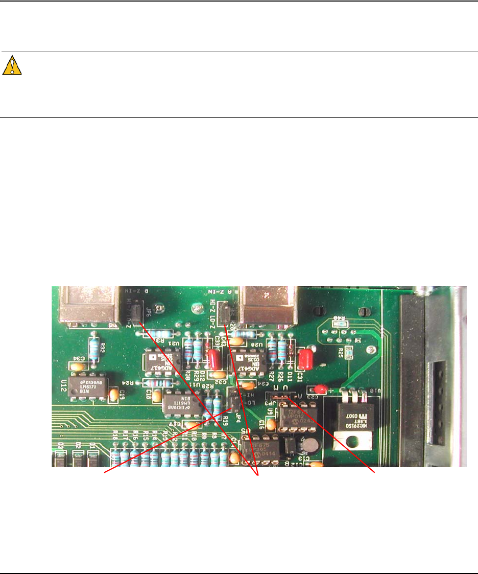
4.4 Configuring for Input Signal and Impedance
The Input Signal and Impedance settings are configured at the factory for a modulated input and
low Z input and output impedance. If the signal sources have a high Z output impedance, then
Caution
When opening the top cover and changing the power supply settings, use proper ESD precautions.
This includes ensuring that you are properly grounded before touching the internal PWA of the
unit to change the jumper settings.
Required for this procedure:
#1 Phillips screwdriver
To change the jumper settings:
1. Disconnect both power supplies from their power source.
2. Using a #1 Phillips screwdriver, remove the top cover.
3. Move the jumper one position to the left to the 2S position.
4. Replace the top cover.
5. Reconnect the power supplies.
4.5 Configuring for Dual Power Supplies
The power supply setting is configured at the factory based upon single or dual power supply
configuration. If you are adding a second power supply to a unit that was originally configured for
a single power supply, you should change the internal jumper setting. The jumper setting ensures
that the power supply LEDs reflect the proper configuration and that the second power supply is
monitored.
Inputs A & B impedance jumpers
configured for the LO-Z (50 Ω).
Gain setting for selected input
impedance. Must follow Input
impedance.
Signal Type jumper configured for
modulated (IRIG-B).
20 4: Troubleshooting the 4092A
Caution
When opening the top cover and changing the power supply settings, use proper ESD precautions.
This includes ensuring that you are properly grounded before touching the internal PWA of the
unit to change the jumper settings.
Required for this procedure:
#1 Phillips screwdriver
To change the jumper setting:
1. Disconnect both power supplies from their power source.
2. Using a #1 Phillips screwdriver, remove the top cover.
3. Move the jumper one position to the left to the 2S position.
4. Replace the top cover.
5. Reconnect the power supplies.
4.6 Replacing Power Supplies
For units with a single power supply, the normal LED state is for one LED to be green and the
other not lit. For units with dual power supplies, the normal LED state is for both LEDs to be
green.
If a power supply LED is red, check that the affected power supply is connected to a properly
functioning 100–240 VAC, 50/60 Hz power source. If the LED remains red, you should replace
the power supply.
For AC power supplies, use only TSC 4501A power supplies. For DC power supplies, use only
TSC 4502A power supplies.
In a unit with dual power supplies, you can hot swap the power supplies. This means you can leave
the working power supply connected to power and all input and output devices connected when
you replace the failed power supply.
Power supply jumper configured for
one power supply (in the 1S position).

4092A Operations and Maintenance Manual 21
Required for this procedure:
#1 Phillips screwdriver
To replace a power supply:
1. Disconnect the power cord from the failed power supply.
2. Using a #1 Phillips screwdriver, remove the two screws from the failed power supply.
3. Using #1 Phillips screwdriver, remove the ground screw.
4. Slide the power supply out of the chassis.
5. Slide the new power supply into the chassis, making sure it clicks into place.
6. Replace the two screws in the power supply.
7. Replace the ground screw in the power supply.
8. Reconnect the power cord to the new power supply.
4.7 Replacing Fuses
If you know that a local event caused blown fuses throughout a rack, you can replace the fuses in
each 4501A power supply. The AC power supplies have two fuses.
The DC power supplies do not have any customer-serviceable fuses.
Required for this procedure:
Small flat-head screwdriver
Replacement fuses for a standard IEC 320 power entry module with fuse (5 x 20 mm,
1 amp, 250 volt fuse)
To replace a fuse:
1. Disconnect the power cables from the power supplies.
2. Using a small screwdriver, open the fuse cover on the power supply.
3. Replace the old fuses as necessary in each power supply.
4. Close the fuse covers.
5. Reconnect the power cables to the power supplies.
4.8 Verifying Operational Problems
If the unit does not operate properly after you have checked the following:
Troubleshot the inputs as described in “4.1 Troubleshooting Input Problems” on page 17
Checked that the correct power is applied to the power supplies
Checked that the fuses are good
return the unit to TSC for repair. For contact information, see “5.1 Warranty Information” on
page 23.
22 4: Troubleshooting the 4092A

4092A Operations and Maintenance Manual 23
5: Warranty and Shipping Information
This chapter provides information on how to contact Timing Solutions Corporation for warranty
service, as well as shipping guidelines for the 4092A.
5.1 Warranty Information
The 4092A carries a warranty from Timing Solutions Corporation for a period of 1 year from date
of shipment.
For repairs, contact Timing Solutions Corporation:
Phone (303) 939-8481
Fax (303) 443-5152
Address written correspondence to:
Timing Solutions Corporation
4775 Walnut Street, Suite 1B
Boulder, CO 80301
USA
5.2 Shipping Information
If you need to ship this unit for any reason, including returning equipment to Timing Solutions for
warranty service, follow these shipping instructions. Failure to follow these instructions may
damage your system.
5.2.1 Packing Instructions
Always ship the 4092A appropriately packaged to protect it from damage.
No cables or connectors may be attached to the rear of the chassis.
Wrap the chassis in plastic to protect against moisture.
24 5: Warranty and Shipping Information

4092A Operations and Maintenance Manual 25
Appendix A: Specifications
A.3 Electrical Specifications
Table 3 lists the electrical specifications for the 4092A.
Table 3: Electrical specifications
Item Specification
Protection Class Class I (Grounded Type)
Power Input Voltage 100–240 V ~ 50/60 Hz 0.5 A, power dissipation ~20 Watts
Note: Fluctuations not to exceed ± 10% of nominal supply voltage.
Power Inlet Type IEC 60320 sheet C14
AC Power Supply Cord Set 18 AWG (0.75 mm2 minimum)
DC Power Supply The external wiring to this connector must be at a minimum 1.5 mm² (14 AWG)
with a 15 A fuse or circuit breaker. A 20 A circuit breaker may be used if the
external wiring is jacketed 14 AWG, with maximum length of 20 feet. An
internal fuse mounted on the power supply carrier board is included to protect
this input but is not field replaceable. Mating connector for the DC power
supply is a AMP 1-350344-0 and 2 sockets are required, AMP 350388-1.
Power Supply Part Numbers AC: TSC 4501A
DC: TSC 4502A
Power Mains Fuse AC: (2) - 250V~1A time lag 5 x 20 mm. Initial shipments will have one fuse.
DC: No customer-serviceable fuses.
Unmodulated Signal Input Frequency: 1–200 kHz
Lo-Z Impedance: 50 Ω ±5 Ω
Hi-Z Impedance: 600 Ω ±10 Ω
Input level: > 1.5 V peak to peak into 50 Ω
Modulated Signal Input Code Format: IRIG-B
Frequency: 1 kHz (IRIG-B)
Lo-Z Impedance: 50 Ω ±5 Ω
Hi-Z Impedance: 600 Ω ±10 Ω
Input level: > 2.8 V peak to peak into 50 Ω
Connectors Input: 2 BNC
Output: 8 BNC
LAN: RJ-45
Gain 0 dB
Isolation > 70 dB
26 Appendix A: Specifications
A.3.1 Environment Specifications
Warning
This unit is for INDOOR USE ONLY. It is not sealed to prevent moisture from entering the
enclosure. Equipment intended to be installed in an enclosed- or open-type equipment rack.
Pollution Degree II per EN61010-1
Installation (Over-Voltage) Category II for transient over-voltages per EN 61010-1
Equipment suitable for continuous operation
Table 4 lists the environmental specifications for the 4092A.
A.4 Physical Specifications
Table 5 lists the physical specifications for the 4092A.
Table 4: Environment specifications
Item Temperature Relative Humidity Altitude
In Use 15°C to 40°C 10% to 85% (non-condensing) 3,000 meters
(9,843 feet)
Storage –40°C to 70°C 5% to 95% (non-condensing)
Transportation –40°C to 70°C 5% to 95% (non-condensing)
Table 5: Physical specifications
Item Specification
Width Standard 19-inch rack mount
Height Standard 1U (~1.75 inches or 4.44 cm)
Depth 12.75 inches or 31.875 cm
Weight Approximately 4.1 kg

4092A Operations and Maintenance Manual 27
Glossary
\n Line feed
\r Carriage return
CNR Command and Response
DHCP Dynamic Host Configuration Protocol
ESD electrostatic discharge
LED light-emitting diode
LSB least significant bit
MSB most significant bit
PDF portable document format
PWA printed wiring assembly
RF radio frequency
TSC Timing Solutions Corporation
28 Glossary

4092A Operations and Maintenance Manual 29
Index
Numerics
4092A
accessing remotely 11
alarms 15
cleaning 9
command interface 11
front panel 3
installing 5
monitoring 11
overview 3
rear panel 3
required cables 5
specifications 25
unpacking 5
A
accessing the 4092A remotely 11
active input channel
selecting from the front panel 8
selecting remotely 8
alarms
checking 11
understanding 15
assigning
gateway address 6
IP address 6
subnet mask 6
autoswitch mode
setting from the front panel 9
setting remotely 9
C
cables
connecting 5
required 5
checking
alarms 11
system status 11
the model number 14
the software version 14
cleaning the 4092A 9
Command-And-Response Port, explained 11
commands
for checking status and alarms 11
for selecting the active input channel 8
for setting autoswitch mode 9
connections
Ethernet 3, 5
input power 5
input signal 3
input signals 5
output signal 3
output signals 5
power 3
conventions, typographic 2
D
DeviceInstaller software 7
dual power supplies, configuring for 19
E
earth symbol 1
Ethernet
connecting 5, 11
port 3, 6, 11
F
fuse
replacing 21
symbol 1
G
gateway address, assigning 6
I
information
shipping 23
input
connector 3
LEDs 3
input channel
selecting active from the front panel 8
selecting active remotely 8
input select LED 3
input signals
connecting 5
specifications 25
troubleshooting 17
installing the 4092A 5
IP address assigning 6
L
LAN
assigning an IP address 6
connecting 5
LAN port symbol 1
Lantronix DeviceInstaller software 7
Lantronix Xport. See Xport.
LEDs
input 3
input select 3
output 3
power 3
M
model number, checking 14
monitoring the 4092A 11
N
network
assigning an IP address 6
30 Index
connecting 5
O
operational problems
verifying 21
output
connectors 3
LEDs 3
output signals
connecting 5
troubleshooting 18
P
packing instructions 23
panels
front 3
rear 3
ports
Command-And-Response 11
Ethernet 11
power
connecting 5
connector 3
LED 3
specifications 25
power supplies
configuring for dual 19
replacing 20
replacing fuses in 21
R
replacing
a fuse 21
power supplies 20
S
safety instructions 5
setting autoswitch mode 9
shipping
information 23
software version, checking 14
specifications
electrical 25
environment 26
physical 26
status, checking 11
subnet mask, assigning 6
symbols 1
earth 1
fuse 1
LAN port 1
system status, checking 11
T
troubleshooting
input problems 17
output problems 18
typographic conventions 2
U
unpacking the 4092A 5
W
warning 1
warning symbol 1
warranty information 23
X
Xport
Ethernet to RS-232 converter 6
user manual 7
