Lanzar E540P Users Manual
Lanzar-Car-Audio-E540P-Users-Manual-435459 lanzar-car-audio-e540p-users-manual-435459
Lanzar Vibe VIBE750S User’s Manual VIBE 740V-750S-540P Troubleshoot Lanzar Vibe VIBE750S |
E750S vibe 740v-750s-540p
PYLE Wave PLE755S 267-820-lanzar-vibe540p-manual
E740V to the manual 4c2553a6-9309-4092-a45d-ec50dce0691b
2015-02-03
: Lanzar Lanzar-E540P-Users-Manual-469049 lanzar-e540p-users-manual-469049 lanzar pdf
Open the PDF directly: View PDF ![]() .
.
Page Count: 24

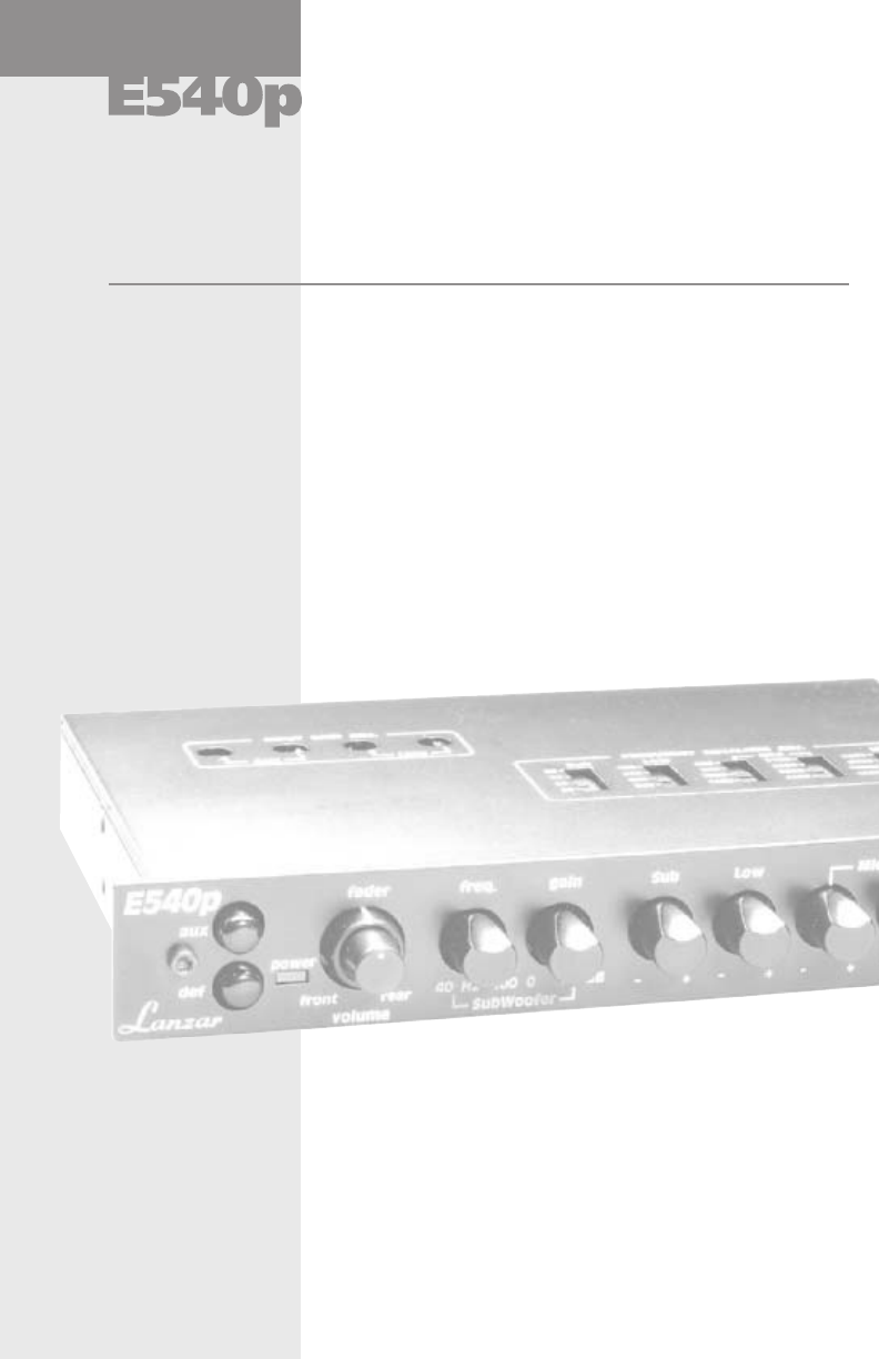
preamp equalizer
with subwoofer crossover
parametric equalizer
with subwoofer crossover
preamp equalizer
E540
E75
© 1999 Lanzar Audio Inc.
Thank you for choosing
Lanzar Audio, and
congratulations on joining
a select group of dedicated
enthusiasts committed to
the very best in mobile
sound performance and
dependability.
You are now the proud
owner of one of the world’s
most sophisticated
electronics components.
This Lanzar product is the
result of an extensive
engineering program with
the sole purpose of creating
the finest mobile audio
experience imaginable.
We’re confident that this
product will provide you
with many years of
outstanding musical
entertainment.
0P
750S
owner’s manual
signal processors

© 1999 Lanzar Audio Inc.

owner’s manual
Congratulations
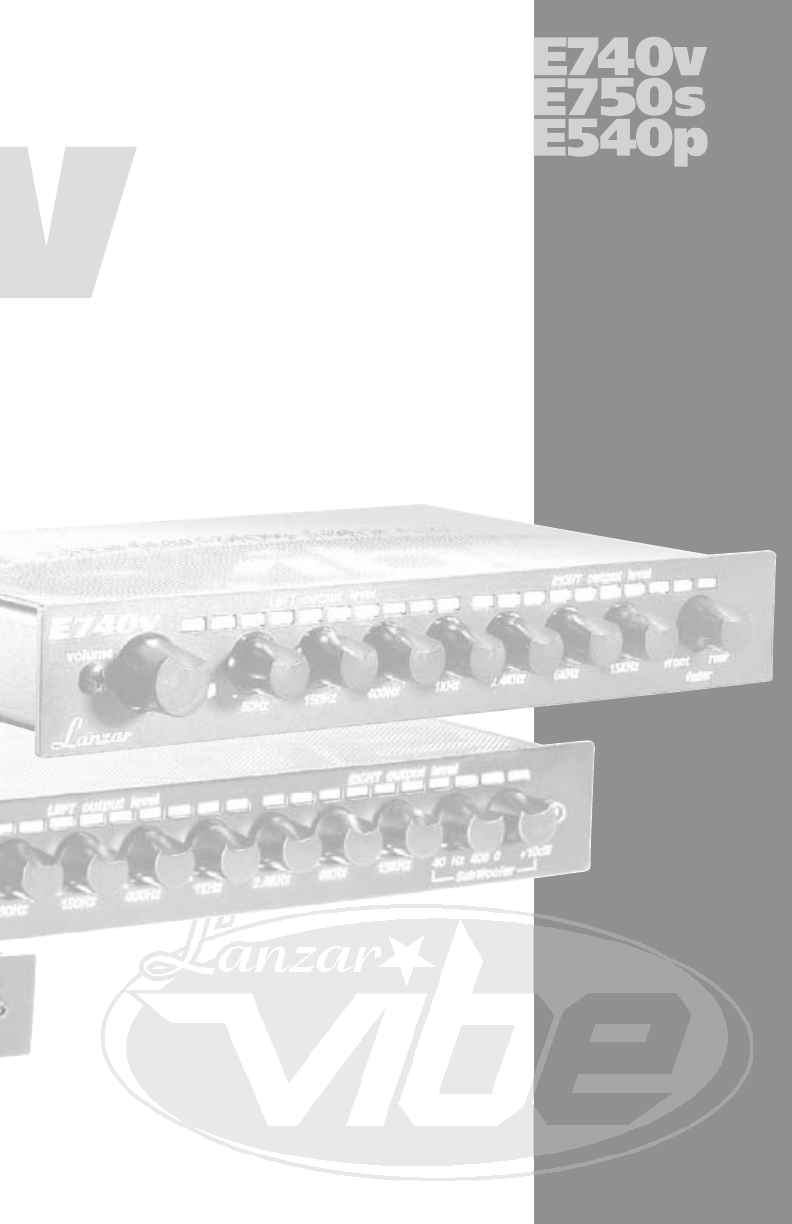
E740v
E740v
E750s
E750s
2
4
6
8
contents
signal processors
E540p
E540p
Installation
Wiring Directions
System Diagrams
Troubleshooting and Precautions
10
12
14
15
16
20
Limited Warranty 21
Features and Specifications
Controls and Operation
Features and Specifications
Controls and Operation
Features and Specifications
Controls and Operation
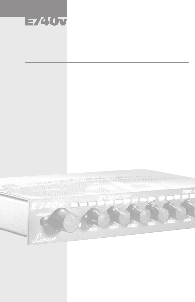
features
preamp equalizer
• 7 Band Graphic Equalizer
• Pre-Amp Input via RCA Jacks
• Output Level Control
• LED Power Level Meter
• 12 dB Boost/Cut
• Rotary Band Control
• Rotary Fader
• 4-Channel RCA Outputs
• Fully Isolated DC-t0-DC Power Supply
• Remote Power On/Off
• Half-DIN Size Cabinet
2
owner’s manual specifications
preamp equalizer
Center Frequencies
60 Hz • 150 Hz
400 Hz • 1 kHz
2.4kHz•6Hz
15 kHz
Frequency Response
15 Hz – 20 kHz
(at +/– 3 dB, 400 mv)
Dimensions,WxDxH (mm)
7.0 x 6.25 x 1
(190 x 115 x 29 mm)
Power Supply Voltage
10 – 16 V Neg. Ground
Current Drain
250 mA Maximum
Separation
60 dB
Signal-to-Noise Ratio (S/N)
90 dB
Output Impedance
1.2 k-Ohm
Total Harmonic Distortion (THD)
(at 400 mV Output)
< 0.025%
Input Level
(for 400 mV Output)
400 mV
pply
3
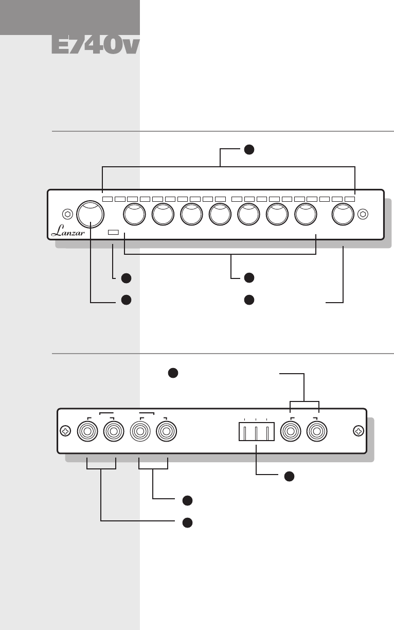
controls
preamp equalizer
Front panel
E740
v
LEFT output level RIGHT output level
volume
60Hz
–+
150Hz
–+
400Hz
–+
1kHz
–+
2.4kHz
–+
6kHz
–+
15kHz
–+
front
rear
fader
4Volume Control
1LED Level Display
3Equalizer Control
5Fader Control
2Power Indicator LED
Rear panel
+12 Rem Gnd INPUT
LR
FRONT
LR
REAR
LR
OUTPUT
9Rear Channel Outputs
8Front Channel Outputs
7Power Connections
(+12V, Remote, Ground)
6Line Channel Inputs
4

owner’s manual operation
preamp equalizer
Control/Connector Function
2Power Indicator LED This LED is illuminated when the unit is
properly powered, grounded and the remote
power has been turned on.
3Equalizer Controls This seven-band equalizer’s rotary controls
give you control over musical frequency
ranges.
7Power Connection Connect to power source as follows:
+12: Connect a red wire of at least 12 gauge to
the car battery or other power source.
GROUND: Connect a black wire of at least 12 gauge
to car chassis for ground connection
REMOTE: Connect an orange wire to remote
activating (12V DC) wire of car stereo or other
head unit.
These rows of LEDs display the Preamp
Output Level. Left and right \channels are
displayed independently at peak levels.
1LED Level Display
4Volume Control Allows adjustment of sound level for particular
program material or source.
• In a 2 Speaker system, the fader control
should be rotated to the position which
provides highest levels for both sets of
speakers.
5Fader Control • In a 2 Amplifier, 4 Speaker system, rotating
the knob to the FRONT side increases the
level of the front speakers; rotating to the
REAR side increase level of the rear speakers.
At mid position, both sets of speakers are at
maximum level
6Line Channel Inputs RCA cables are used to connect the front
input signal from head unit or other source.
8Front Channel Outputs RCA cables are used to connect the front
channel ouputs to the front channel amplifier
inputs.
9Rear Channel Outputs RCA cables are used to connect the rear
channel ouputs to the rear channel amplifier
inputs.
s
)
5
• 7 Band Graphic Equalizer
• Pre-Amp Input via RCA Jacks
• Output Level Control
• LED Power Level Meter
• 12 dB Boost/Cut
• Subwoofer Frequency Control
• Subwoofer Boost Control
• Front and Rear Fader Control
• 6-Channel RCA Outputs
• Night Illumination
• Remote Power On/Off
• High Impedance Input
• Half-DIN Size Cabinet
equalizer with
subwoofer crossover
features
6
owner’s manual specifications
Center Frequencies
60 Hz • 150 Hz
400 Hz • 1 kHz
2.4kHz•6Hz
15 kHz
Frequency Response
20 Hz – 20 kHz
(at +/– 3 dB, 400 mv)
Current Drain
250 mA Maximum
Subwoofer Boost Control
0-10 dB
Subwoofer Frequency
40-400H
Z
Separation
60 dB
Signal-to-Noise Ratio (S/N)
85 dB
Output Impedance
1.2 k-Ohm
Total Harmonic Distortion (THD)
(at 400 mV Output)
< 0.025%
Input Level
(for 400 mV Output)
400 mV
7
Dimensions,WxDxH (mm)
7.0 x 6.25 x 1
(190 x 115 x 29 mm)
Power Supply Voltage
10 – 16 V Neg. Ground
equalizer with
subwoofer crossover
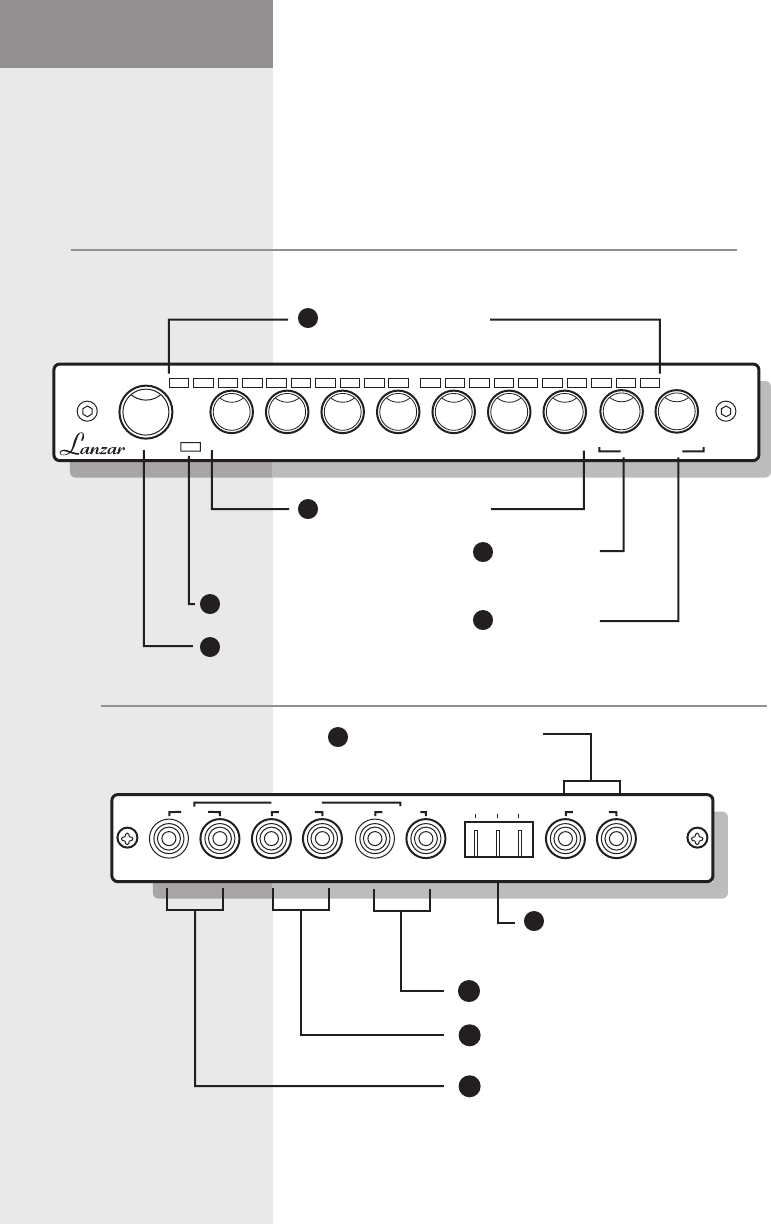
controls
Front panel
Fader Control
LED Level Display
Equalizer Controls
Subwoofer
Frequency
Control
Power Indicator LED
Rear panel
Front Channel Outputs
Power Connections
(+12V, Remote, Ground)
Line Channel Inputs
8
Subwoofer
Boost
Control
Subwoofer Channel Outputs
E750S
+12 Rem Gnd INPUT
LR
SUB
LR
REAR
LR
OUTPUT FRONT
LR
E7
5
0
s
LEFT output level RIGHT output level
60Hz
–+
150Hz
–+
400Hz
–+
1kHz
–+
2.4kHz
–+
6kHz
–+
15kHz
–+
0 +10dB
front rear
fader 40 400
–+
Subwoofer
Rear Channel Outputs
8
9
10
11
7
6
5
4
3
2
1
equalizer with
subwoofer crossover

owner’s manual operation
Control/Connector Function
9
E750S
equalizer with
subwoofer crossover
This seven-band equalizer’s rotary controls give
you control over musical frequency ranges.
Equalizer Controls
2
• In a 2 Speaker system, the fader control should
be rotated to the position which provides highest
levels for both sets of speakers.
• In a 2 Amplifier, 4 Speaker system, rotating the
knob to the FRONT side increases the level of
the front speakers; rotating to the REAR side
increase level of the rear speakers. At mid position,
both sets of speakers are at maximum level.
Fader Control
4
Line Channel Inputs RCA cables are used to connect the front
input signal from head unit or other source.
7
Subwoofer Boost Control Lets you adjust the subwoofer boost level
froma0to+10dB increase.
6
Subwoofer
Frequency Control
Lets you adjust the subwoofer frequency and
crossover point from 40-400 Hz.
5
Power Connection Connect to power source as follows:
+12: Connect a red wire of at least 12 gauge to
the car battery or other power source.
GROUND: Connect a black wire of at least 12 gauge
to car chassis for ground connection
REMOTE: Connect an orange wire to remote
activating (12V DC) wire of car stereo or other
head unit.
8
Front, Rear &
Subwoofer Outputs
RCA cables are used to connect the front
channel outputs to the front channel amplifier
inputs, the rear channel outputs to the rear
channel amplifier inputs, and the sub outputs
to the subwoofer amplifier inputs.
9
10
11
This LED is illuminated when the unit is
properly powered, grounded and the remote
power has been turned on.
Power Indicator LED
3
These rows of LEDs display the Preamp
Output Level. Left and right \channels are
displayed independently at peak levels.
LED Level Display
1
• 5 Band Graphic Equalizer
• 5 Band Parametric Control
• 20 Frequency Band Selector
• Adjustable Subwoofer Crossover
• Pre-amp Line & Aux Inputs via RCA Jacks
• Output Volume Control
• Input Gain Adjustments
• Frequency Gain Control
• Rotary Fader
• Rotary Band Control
• Defeat Switch
• 6-Channel RCA Outputs
• Fully Isolated DC-to-DC Power Supply
• Remote Power On/Off
parametric equalizer
features
10
A Jacks
ply
owner’s manual specifications
Sub Band Parametric Range
Low Band Parametric Range
Mid Band Parametric Range
High Band Parametric Range
35•50•65•80Hz
150 • 200 • 260 • 320 Hz
600 • 800 • 1000 • 1200 Hz
2.1 • 2.8 • 3.5 • 4.2 KHz
7•9.5•12•15KHz
Frequency Response
20 Hz – 20 kHz
(at +/– 3 dB, 400 mv)
Current Drain
.5 A Maximum
Control Range
+ 12dB
Subwoofer Frequency
Variable from 40-400H
Z
Separation
60 dB
Signal-to-Noise Ratio (S/N)
85 dB
Output Impedance
1.2 k-Ohm
Total Harmonic Distortion (THD)
(at 400 mV Output)
< 0.025%
Input Level
(for 400 mV Output)
400 mV
11
Dimensions,WxDxH (mm)
7.0 x 6.25 x 1
(190 x 115 x 29 mm)
Power Supply Voltage
DC, 10 – 16 V Neg. Ground
parametric equalizer
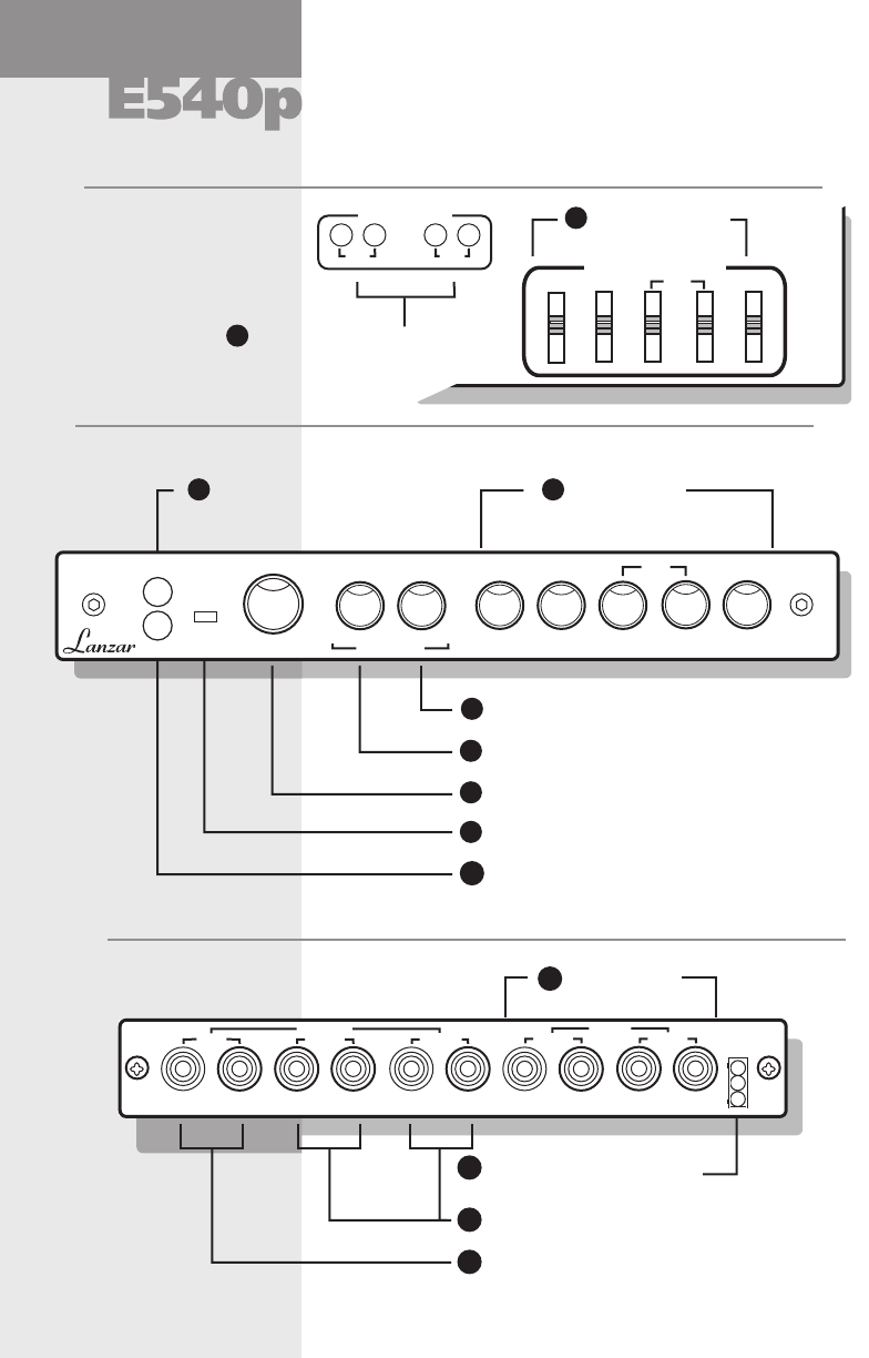
controls
Front panel
Power Indicator LED
Parametric
EQ Controls
Subwoofer Gain Control
Volume and Fader Control
Aux Input Switch
Rear panel
Front & Rear Channel Outputs
Power Connections
(+12V, Remote, Ground)
Line & Aux
Inputs
12
Subwoofer Frequency Control
Sub Channel Outputs
parametric equalizer
Top panel
Line
Aux
Input Gain Adj.
EQ Frequency Adj.
35-
50-
65-
80-
150-
200-
260-
320-
600-
800-
1000-
1200-
2.1-
2.8-
3.5-
4.2-
7-
9.5-
12-
15-
HighMid
LowSub
Input Gain Adjustments
EQ Frequency
Controls
Defeat Switch
E
540
P
front rear
Volume
Fader
Mid
–+–+
Low
–+
Sub
–+
–+
Freq.
Subwoofer
0 +10dB40 400
Gain
Aux
Def
–+
High
AUX
LR
SUB
LR
REAR
LR
OUTPUT FRONT
LR
LINE INPUT
2
4
7
6
5
8
9
10
11
3
1
12
13
LR

owner’s manual operation
Control/Connector Function
13
parametric equalizer
These switches determine the frequencies the gain
knobs on the front panel will affect. Setting a switch
on one of the 5 bands on top of the equalizer permits
the corresponding control on the front panel to raise
or lower the gain at that frequency.
EQ Frequency Controls
Allows you to adjust the left and right channel
input sensitivity to match the output level from
your line or auxiliary source.
Input Gain Adjustments
Subwoofer Gain Control Turning this control clockwise increases the
subwoofer channel level.
Volume and Fader Control The Volume adjusts the total output level. Fader
adjusts the output balance between the front and
rear amplifiers.
Power Indicator LED This indicator lights up when the unit is properly
powered, grounded, and the remote power lead
has power to it.
Defeat Switch When the “DEF” switch is in the on position the
equalizer functions are bypassed. Depressing the
“DEF” switch again will restore the equalizer’s
operation.
Power Connections
(+12V, Remote, Ground)
1. Connect the red wire to the car battery or
other power source.
2. Connect the orange wire to the power antenna
activating wire of the car stereo.
3. Connect the black wire to the car’s chassis for
the proper ground connection.
Line and Auxiliary Inputs RCA cables are used to connect your car stereo
head unit, CD player, or other source to either
the line or aux inputs.
Subwoofer Frequency
Control
By rotating this selector you can choose any
crossover frequency from 40Hz to 400Hz. Turning
the control clockwise permits more upper bass
to travel through the sub channel.
Front, Rear &
Subwoofer Outputs
RCA cables are used to connect the front channel
outputs to the front channel amplifier inputs, the
rear channel outputs to the rear channel amplifier
inputs, and the sub outputs to the subwoofer
amplifier inputs.
1
2
5
7
6
8
9
10
11
12
13
This switch selects the aux or line inputs.
Aux Input Switch
3
Parametric EQ Controls
Turning the controls clockwise increases the level
of the sound at the frequency that you have set on
the EQ’s top panel. Counter-clockwise reduces the
level at that frequency. Choose the settings which
best match your system and your prefered audio
response.
4
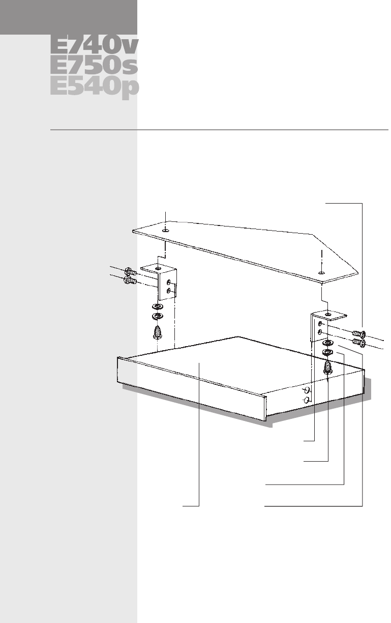
installation
Please take the time to install your new
Lanzar Signal Processor securely, according
to this diagram, using the hardware provided.
Signal Processor enclosure
Mounting Bracket
4x12mm
self-tapping screw (2)
4 mm spring
washer (2)
4 mm plain
washer (2)
4x 6 mm machine screw (4)
Dashboard
Installing your signal processor under the dash of your car
14
This Half-DIN size unit can also be installed in the
dash adjacent to the head unit, provided that there
is a slot available.

owner’s manual wiring
Connect 12V DC from a constant battery source to a +12V slip-on spade terminal
and install a one (1) amp fuse in line.
Connect the signal processor’s GROUND to a good chassis ground, near where
the unit is mounted, or to the case of the head unit.
Connect the signal processor’s REMOTE TURN-ON lead to the remote turn-
on lead out of the head unit, and install a 1/2 amp fuse in line. (A relay
should be used if turning on more than one component, such as EQ’s,
crossovers or amplifiers.)
Connect stereo RCA cables from the head’s left and right front outputs to
the left and right inputs of the signal processor.
Connect stereo RCA cables from the left and right outputs, (and low, mid
and high outputs if applicable), of the signal processor to the left and right
inputs of your amplifier(s) or additional signal processor(s).
Turn the unit on, and adjust the input gain on the signal processor to match
the output of the head unit (1/2, or at center position, is about 1 V). Be careful
not to overdrive the input of your amplifier(s) or signal processor(s). Use
clip detectors to adjust output.
Adjust each of the crossover or equalizer controls to achieve the desired
sound characteristics.
15
signal processors
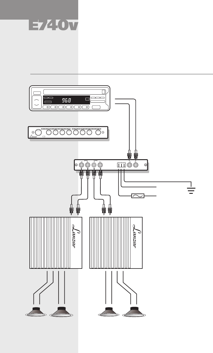
preamp equalizer
Basic 2-Amp/4-Speaker system application using the E740v
Head unit (Stereo, CD Player, Tape Deck, etc.)
E740v
LEFT output level RIGHT output level
volume
60Hz
–
+150Hz
–+
400Hz
–+
1kHz
–+
2.4kHz
–+
6kHz
–+
15kHz
–+
front rear
fader
+12 Rem Gnd INPUT
LR
FRONT
LR
REAR
LR
OUTPUT
Lanzar Vibe E740v Preamp Equalizer
REAR CHANNEL
Power Amplifier FRONT CHANNEL
Power Amplifier
to Ground (Black)
to Remote On
(Orange)
to +12v Battery
(Red)
Left and Right
Line Inputs
Rear Panel
Left and Right
Line Outputs
from Head Unit
REAR CHANNEL
Speakers FRONT CHANNEL
Speakers
16
Fuse: 1A
system diagram
–+
–+ –+
–+ +
owner’s manual
17
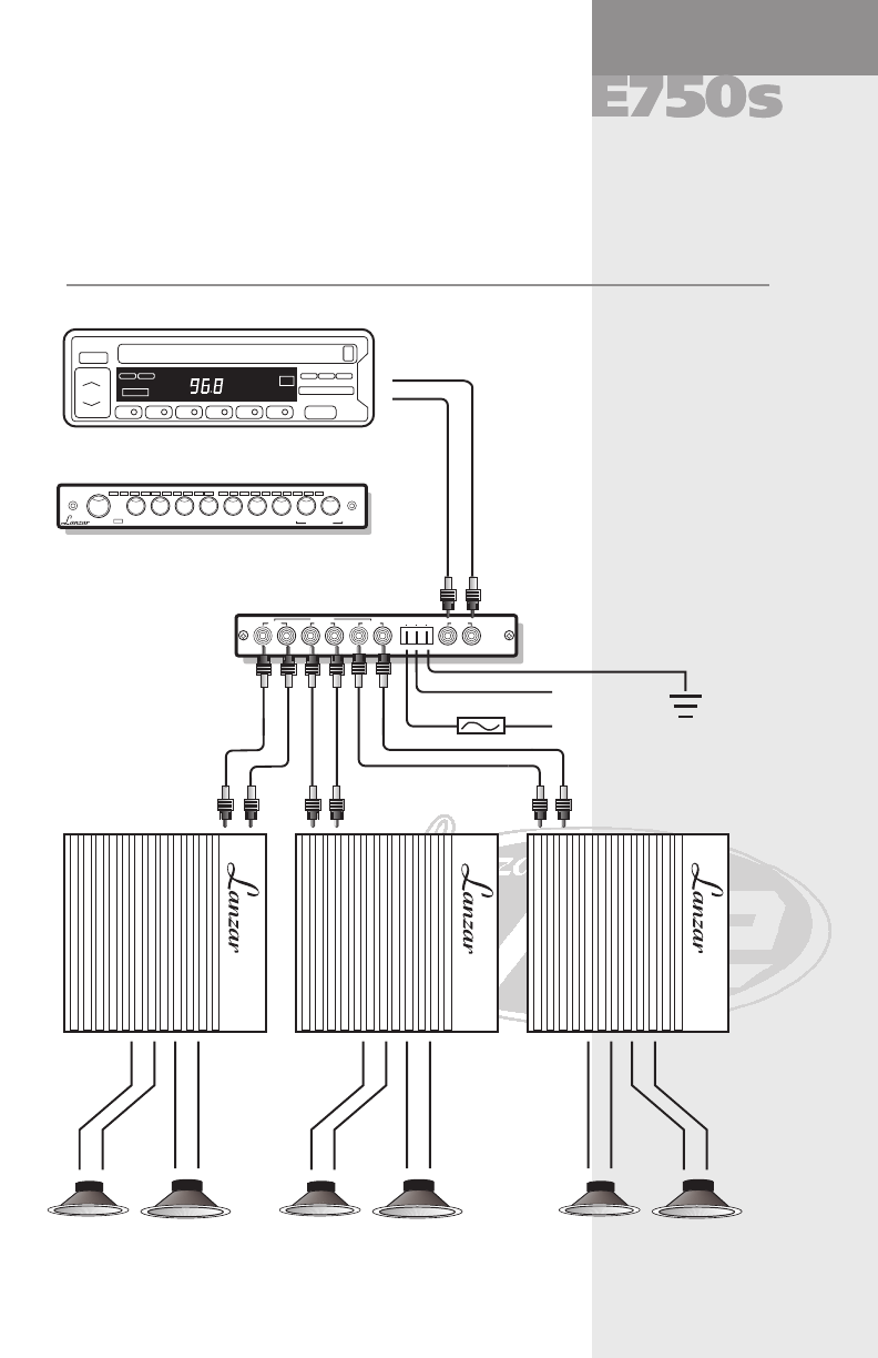
system diagram
4-Speaker and subwoofer system application using the E750s
Head unit (Stereo, CD Player, Tape Deck, etc.)
Lanzar Vibe E750s Equalizer & Crossover
REAR CHANNEL
Power Amplifier FRONT CHANNEL
Power Amplifier
to Ground (Black)
to Remote On
(Orange)
to +12v Battery
(Red)
Left and Right
Line Inputs
Rear Panel
Left and Right
Line Outputs
from Head Unit
REAR CHANNEL
Speakers FRONT CHANNEL
Speakers
Fuse: 1A
+12 Rem Gnd INPUT
LR
SUB
LR
REAR
LR
OUTPUT FRONT
LR
SUB CHANNEL
Speakers
SUB CHANNEL
Power Amplifier
E750
s
LEFT output level RIGHT output level
60Hz
–
+150Hz
–+
400Hz
–+
1kHz
–+
2.4kHz
–+
6kHz
–+
15kHz
–+ 0 +10dB
front rear
fader 40 400
–+
Subwoofer
equalizer with
subwoofer crossover
–+
–+ –+
–+
–+
–+
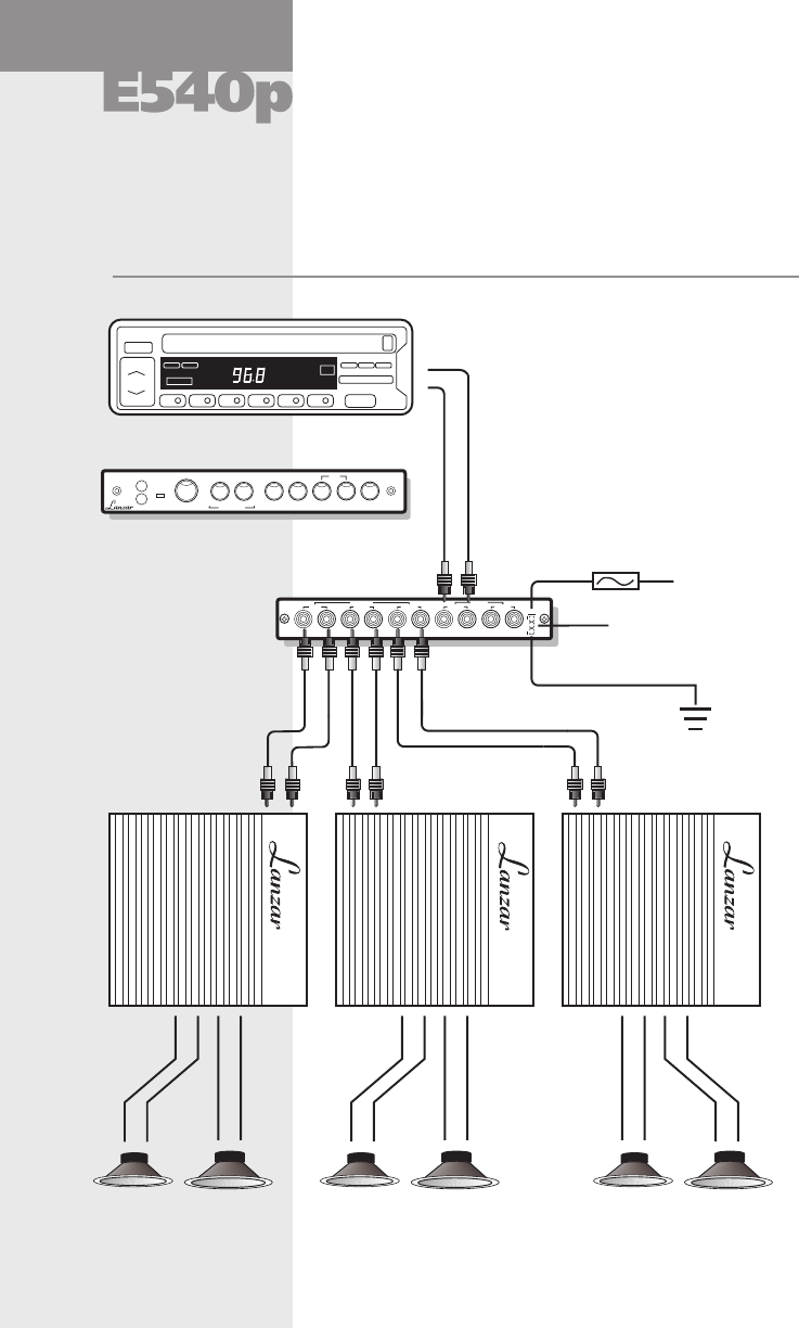
system diagram
19
4-Speaker and subwoofer system application using the E540P
Head unit (Stereo, CD Player, Tape Deck, etc.)
Lanzar Vibe E540PParametric Equalizer
REAR CHANNEL
Power Amplifier FRONT CHANNEL
Power Amplifier
to Remote On
(Orange)
to +12v Battery
(Red)
Left and Right
Line Inputs
Rear Panel
Left and Right
Line Outputs
from Head Unit
REAR CHANNEL
Speakers FRONT CHANNEL
Speakers
Fuse: 1A
SUB CHANNEL
Speakers
SUB CHANNEL
Power Amplifier
parametric equalizer
E
540
P
front rear
Volume
Fader
Mid
–+–+
Low
–+
Sub
–+
–+
Freq.
Subwoofer
0 +10dB40 400
Gain
Aux
Def –+
High
AUX
LR
SUB
LR
REAR
LR
OUTPUT FRONT
LR
LINE INPUT
to Ground (Black)
–+
–+ –+
–+
–+
–+

owner’s manual
troubleshooting
If you experience.... Check that:
Level of sound is low. • Wiring is not loose or cables
misconnected/disconnected
• RCA cables are not faulty.
Background noise is
too high.
• Wiring is not loose or cables
misconnected/disconnected
• RCA cables are not faulty.
20
Signal Processor does not
turn on.
• Remote Turn-On wire has 12V
• 12V wire has 12V
• Ground wire is properly connected
precautions
• Never drive with the volume raised so high you cannot hear what is occuring in traffic
around you.
• Be aware that repeated exposure to excessive volume levels can permanently damage
your hearing!
• Keep all electronics away from moisture, dust, extreme heat or extreme vibrations.
• Lanzar Audio products are capable of sound pressure levels in excess of 150 dB.
Continuous exposure to sound pressure levels over 100 dB may cause permanent
loss of hearing. Use common sense and PRACTICE SAFE SOUND.
Enjoy your system, but use it wisely and safely!
signal processors

CAR AUDIO
Quality
Technology
Performance
Quality
Technology
Performance
All Lanzar Signal Processors are carefully constructed and thoroughly
tested before shipment. Units purchased in the USA are warranted
to be free of defects in material and workmanship for three (3) years
from the date of purchase. This warranty is limited to the original
retail purchaser of the Signal Processor.
Should the unit fail due to a factory defect in material or workmanship,
your unit will be repaired or replaced at the sole discretion of Lanzar.
To obtain warranty service, you must first call our Consumer Return
Hotline number at (718) 236-6948 to obtain a Return Authorization
(RA) number. This RA Number must appear on the outside of your
package and on all paperwork relating to your return.
When returning the unit to us for warranty service, it must be
carefully packed and shipped prepaid to:
R.A. #______________
Lanzar Service Center
1600 63rd Street
Brooklyn, NY 11204
You must also include the following items with your return:
• A copy of your sales receipt or other proof of purchase
• A brief letter indicating the problem you are experiencing with
the product
• Include in your letter your return address, daytime phone number
and RA Number
• Also include a check or money order for $15.00 for return shipping,
handling and insurance, or provide your VISA/MasterCard
number with expiration date.
Our obligation under this warranty is limited to the repair or
replacement of the defective unit when it is returned to us prepaid.
This warranty will be considered void if the unit was tampered with,
improperly serviced, or subject to misuse, neglect or accidental
damage.
All implied warranties of merchantability and fitness for a particular
purpose are limited in duration to the length of the warranty. Lanzar
expressly disclaims any liability for incidental or consequential
damages caused by product defects. This warranty does not cover
any expense incurred in the removal and/or reinstallation of the
Signal Processor. Lanzar’s total liability will not exceed the purchase
price of the Signal Processor.
Some states do not allow the exclusion or limitation of incidental or
consequential damages, or limitations on how long an implied
warranty lasts, so the above limitations and exclusions may not apply
to you. This warranty gives you specific legal rights, and you may
also have other rights which vary from state to state.
Limited Warranty Policy
Lanzar Audio Inc.
1600 63rd Street, Brooklyn, NY 11204 (718) 236-6948
warranty
