Larcan MXI005U Digital Television Broadcast Translator User Manual Heading 3
Larcan Inc Digital Television Broadcast Translator Heading 3
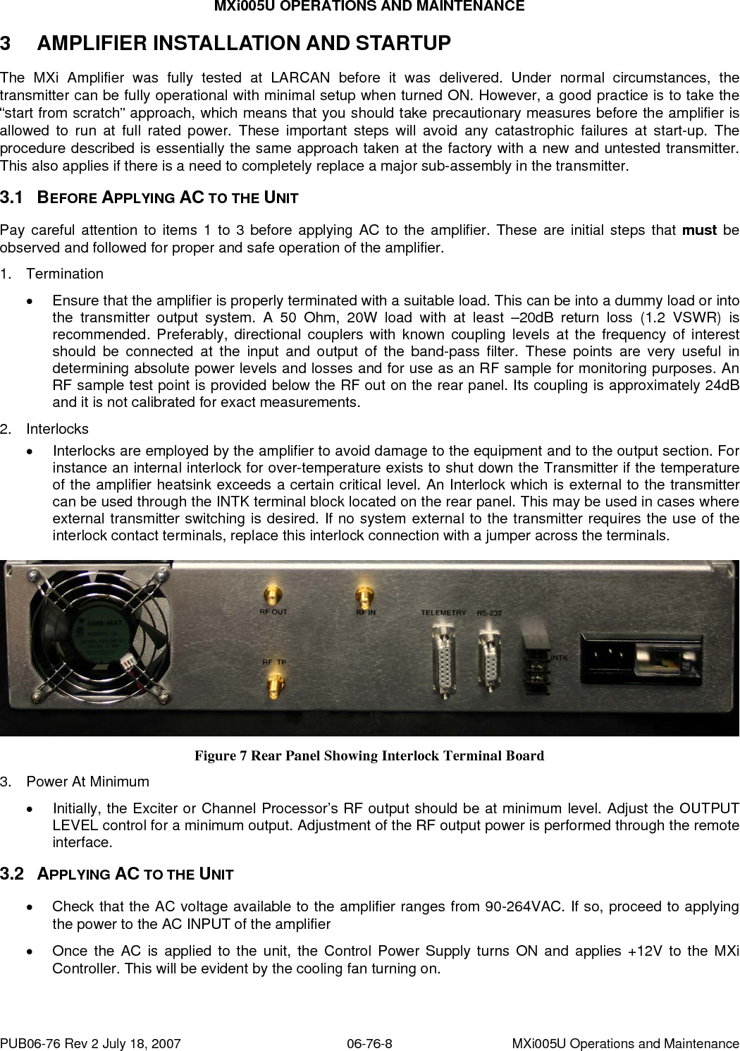
UserManual.wiki
>
Larcan
>
MXI005U User Manual
users manual
Navigation menu
Upload a User Manual
Namespaces
Wiki Guide
HTML
PDF
Info
Views
User Manual
Discussion / Help
Navigation
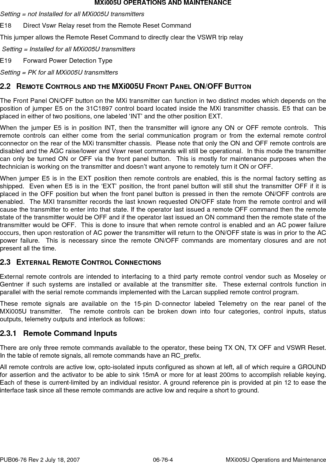
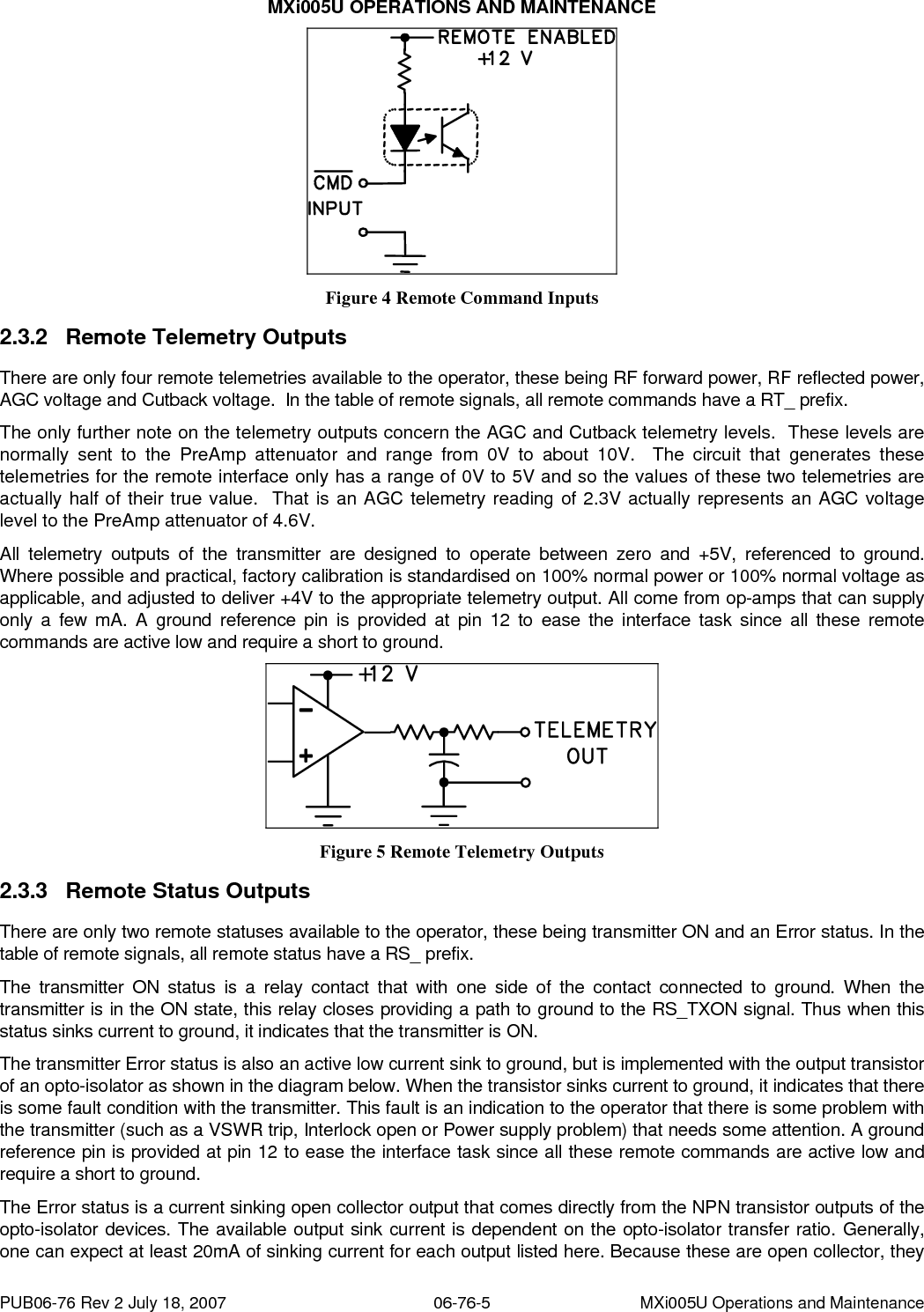
![MXi005U OPERATIONS AND MAINTENANCE can be connected to maximum 30 VDC output. The active (true) condition whether high or low will depend on the specific status output. Figure 6 Remote Status Outputs 2.3.4 2.4 External1 Interlock There is a pair of terminals on the D-connector that is used for an external interlock to interface to any site alarms or shutdown conditions. These pins would expect a dry contact that is closed when there is no error condition. This External #1 interlock is in parallel with the two pin terminal block on the rear of the MXi transmitter chassis. The MXi applied its own +12V to one side of this interlock (the Ext1+ line) and will sense this +12V on the other interlock side (the Ext1- line). REMOTE SIGNAL PIN# DESCRIPTION RC_TXON 1 Control, Transmitter ON RC_VSWRRst 2 Control, VSWR Reset RS_TXON 3 Status, Transmitter ON Spare [Unused] 4 RT_FwdPwr 5 Telemetry, Forward Power Spare [Unused] 6 RT_CutBack 7 Telemetry, Cutback Voltage (1/2 Scale) Ext1- 8 External Interlock, Normally Open RC_TXOFF 9 Control, Transmitter OFF Spare [Unused] 10 RS_TXErr 11 Status, Transmitter Error Ground Reference 12 Ground Reference RT_RflPwr 13 Telemetry, Reflected Power RT_AGC 14 Telemetry, AGC Voltage (1/2 Scale) Ext1+ 15 External Interlock, (+12V Armed) EXTERNAL TRANSMITTER INTERLOCK The MXi transmitter provides the customer a set of contacts where an external interlock can be applied to control the ON state of the transmitter. The purpose of this interlock is to shut down the transmitter if there is sensed an emergency condition (such as a building fire or smoke alarm) or it there is some RF output switch that is going to be moved and the RF output of the transmitter needs to be shut off temporarily when the switch is in transit. If there is no application for this interlock then the customer must insure that it is shorted out (i.e., closed) so that the transmitter is enabled to be turned ON. PUB06-76 Rev 2 July 18, 2007 06-76-6 MXi005U Operations and Maintenance](https://usermanual.wiki/Larcan/MXI005U/User-Guide-1231646-Page-9.png)