Larcan MXI1002U Digital Television Translator User Manual Heading 3
Larcan Inc Digital Television Translator Heading 3
Larcan >
Contents
Amplifier Chassis PUB
MXi501U/1002U AMPLIFIER CHASSIS
CONTENTS
1 MXi501U/1002U AMPLIFIER.........................................................................................................................................1
FIGURES
FIGURE 1 MXI501U/1002U AMPLIFIER WIRING SCHEMATIC......................................................................................................2
PUB11-013 Rev 1 July 2011 11-013-i MXi501U/1002U Amplifier Chassis
MXi501U/1002U AMPLIFIER CHASSIS
1 MXi501U/1002U AMPLIFIER
The Amplifier Chassis Assemblies 41D2270G1&G2 consists of a standard 19" rack mountable 5.25" (3RU)
enclosure containing the amplifier heatsink assembly, a fan array assembly consisting of four DC cooling fans, a
controller board with built-in RF detectors and a rear panel assembly with connectors for interfacing to external
equipment. The MXi501 chassis (G1) has a front panel consisting of ON/OFF, RESET switches and an
LCD/Touchpad. The MXi1002 does not have these on the front panel as they are located in the power supply
chassis
The rear of the AMPLIFIER has the following connectors:
• RS232 SERIAL nine-pin connector
• REMOTE CONTROL 15-pin D-shell connector
• RF IN SMA connector
• INTERLOCK terminal board
• RF TP SMA connector – RF sample
• RF OUT N connector
• Control/Auxiliary power supply connector.
• 50V power supply connector.
The amplifier is a broadband amplifier, thus it is operational to cover the entire UHF television spectrum ranging in
frequencies from 470MHz to 860MHz.
Main DC power to the amplifier assembly comes from the high efficiency switching power supply (separate
chassis). There is a second auxiliary +12V power supply which is used for powering the controller and the cooling
fans.
The heatsink cooling fans are the +12VDC, 4-inch muffin model. They are energized when the controller turns on
the main power supply to power amplifier. The voltage is supplied to the amplifier from the 12V six-pin connector
on the rear panel and it is connected to the controller PC board connector, J8. As built, the cooling fans push air
from the front panel through the heatsink. This assembly is located underneath the MXi Controller board.
A thermal switch is mounted on the heatsink. If this temperature increases beyond the trip point of the thermal
switch of 76°C, its contact opens and breaks the interlocking circuit of the MXi amplifier. The interlock circuit
ultimately controls the power supply to the power amplifier and therefore shuts down and remains OFF until the
heatsink cools down.
A directional coupler is mounted at the rear of the heatsink and provides forward and reflected RF signals to the
controller. These RF samples are detected and processed on the MXi controller to provide DC outputs
corresponding to these signals. They are then used for AGC, VSWR supervision.
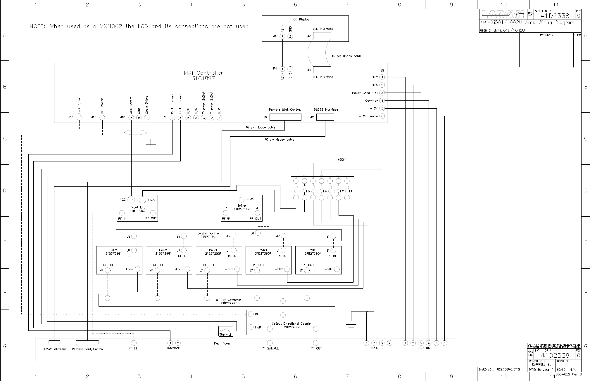
The chassis is wired according to the functional diagram 41D2238 as shown in Figure 1
PUB11-013 Rev 1 July 2011 11-013-1 MXi501U/1002U Amplifier Chassis

MXi501U/1002U AMPLIFIER CHASSIS
Figure 1 MXi501U/1002U Amplifier Wiring Schematic
PUB11-013 Rev 1 July 2011 11-013-2 MXi501U/1002U Amplifier Chassis