Larcan MXI101V Digital Television Broadcast Translator User Manual Heading 3
Larcan Inc Digital Television Broadcast Translator Heading 3
Larcan >
User manual

TSM21Q-365
MXi101V AMPLIFIER
TECHNICAL SERVICE MANUAL
LARCAN INC.
228 AMBASSADOR DRIVE
MISSISSAUGA, ONTARIO
CANADA L5T 2J2
PHONE: (905) 564-9222
FAX: (905) 564-9244
EMAIL: techservices@larcan.com
TSM21Q-365 Rev 0
July 17, 2009
1
MXI101V TECHNICAL SERVICE MANUAL
CONTENTS
TSM20-365 MXi201U TECHNICAL SERVICE MANUAL
1 MXi201U AMPLIFIER–INTRODUCTION ..................................................................................................................3
2 SAFETY NOTICES..........................................................................................................................................................4
2.1 BERYLLIUM OXIDE WARNING ......................................................................................................................................4
2.2 OTHER TOXIC MATERIALS ...........................................................................................................................................4
2.3 DANGEROUS VOLTAGES...............................................................................................................................................4
2.3.1 Switch to Safety....................................................................................................................................................5
3 LARCAN PARTS, ASSEMBLIES, ASSEMBLY DRAWINGS AND SCHEMATIC NUMBERS...........................7
3.1 VENDOR STANDARD PART NUMBERS...........................................................................................................................7
3.2 LARCAN NUMBERS FOR PARTS, ASSEMBLIES AND DOCUMENTATION .......................................................................7
3.3 LEADED RESISTORS......................................................................................................................................................8
3.4 SURFACE MOUNT RESISTORS 1/4W AND LESS .............................................................................................................8
3.5 SURFACE MOUNT CAPACITORS ....................................................................................................................................9
3.6 PARTS LISTS .................................................................................................................................................................9
3.6.1 Production Changes.............................................................................................................................................9
FIGURES
FIGURE 1 MXI AMPLIFIER HEATSINK ASSEMBLY ........................................................................................................................3
TSM21Q-365 Rev 0 July 17, 2009 MXi101V 2
MXI101V TECHNICAL SERVICE MANUAL
1 MXI101V AMPLIFIER–INTRODUCTION
This Technical Service Manual contains publications (PUBs) describing the technical details of the MXi101V
amplifier, as well as the overall operating instructions, including the bench test procedures of the amplifier stages
incorporated in this unit. It also covers the transmitter’s start-up operation, and troubleshooting, as well as basic
transmitter maintenance guidelines.
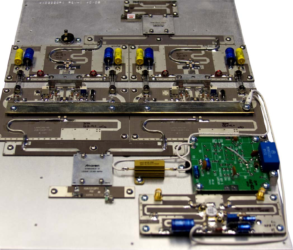
The RF section of the MXi101V Amplifier consists of a heatsink assembly that includes three cascaded
broadband amplifier modules and a directional coupler. Figure 1 shows the layout of an MXi201 assembly. The
MXi101V utilizes one of these output amplifiers only.
Figure 1 MXi Amplifier Heatsink Assembly
Also mounted on the heatsink is a thermal switch that protects the amplifier from over temperature conditions.
TSM21Q-365 Rev 0 July 17, 2009 MXi101V 3
MXI101V TECHNICAL SERVICE MANUAL
2
2.1
2.2
2.3
SAFETY NOTICES
This section provides general guidance and information for the operation, maintenance, and service personnel
who are familiar with the hazards of working with high-powered electronic circuits. This manual does not detail all
of the safety precautions which should be observed when servicing this or any other electronic equipment.
Service by inadequately trained or inexperienced personnel can result in personal injury or death and/or
damage to the equipment.
Important: All personnel concerned with the servicing of this equipment should be thoroughly familiar with
standard first aid procedures for the treatment of electrical burns and shock, including cardio-pulmonary
resuscitation (CPR).
Use the “buddy” system, with one person performing the actual service and a colleague observing. The observer
must be familiar with the work being performed and within sight and sound of the person doing the work. The
observer should not be engaged in any other work or be otherwise distracted; he must be available instantly in
case of accident.
Always have the observer with you when you work on the transmitter.
BERYLLIUM OXIDE WARNING
Internal thermal management in certain RF devices in this equipment is accomplished through the use of
Beryllium Oxide ceramic material. Do not break open any RF power transistors, or otherwise dismantle them.
Beryllium Oxide is a hard white ceramic used as insulation for heatsinking of RF power semiconductors. Beryllium
Oxide is a poison. In case of accidental breakage of devices, do not inhale the resulting beryllium dust and
avoid getting beryllium dust in your mouth. Do not let beryllium into your blood stream through cuts or
open wounds. Seek immediate medical attention if the dust enters your body in any manner. Avoid cuts by
wearing gloves while picking up the broken pieces. Be careful – do not inhale dust while replacing or emptying
vacuum cleaner filter bags and wash your hands thoroughly afterward. Wash your hands thoroughly after
replacing RF power devices. Dispose of defective RF power devices only through approved toxic waste facilities.
Wear gloves when picking up the pieces. Wash your hands thoroughly after replacing devices. Dispose of defective
devices only through approved toxic waste facilities.
When cleaning up after an accidental breakage, remember to wear a respirator mask to avoid inhaling the dust while
replacing or emptying vacuum cleaner filter bags and to wash your hands well after servicing the vacuum cleaner. If
possible, use a wet vacuum, in which the dust gets trapped in water.
OTHER TOXIC MATERIALS
The non-metallic coverings of some coaxial cables used in this equipment are flammable and can transmit fire
when ignited. Other wire coverings are not capable of supporting combustion but any non-metallic covering when
heated sufficiently can emit dense smoke and acid gases, which can be highly toxic and often corrosive.
Solvents and glues can emit toxic vapors and can be flammable. Read and understand the directions on the
containers and ensure that they are used only in well ventilated locations.
DANGEROUS VOLTAGES
This equipment has been designed to protect operating personnel from accidental contact with dangerous voltages,
by means of shields and covers. It is extremely important that any protective covering devices be kept in place at all
times.
While all practical safety precautions have been adopted to safeguard personnel from possible injury, both
supervisory and operating personnel are urged to ensure that the safety rules detailed below are followed as an
established routine at all times. The following four Rules are the standard safety guidelines for working with and
around transmitters.
TSM21Q-365 Rev 0 July 17, 2009 MXi101V 4
MXI101V TECHNICAL SERVICE MANUAL
Rule #1 KILL THE AC POWER BEFORE IT KILLS YOU
Under no circumstances should any person reach within the cabinets for the purpose of servicing or
adjusting the equipment without first disconnecting the AC power or without the immediate presence of
another person capable of rendering aid. The “buddy” system is encouraged for transmitter work.
Rule #2 DO NOT TAMPER WITH INTERLOCKS OR SAFETY SHIELDS
Under normal circumstances, no safety shield should be removed.
Rule #3 REMOVE PERSONAL JEWELRY WHEN WORKING ON THE EQUIPMENT
The mains AC power to this transmitter can deliver high currents capable of melting metallic tools or
personal jewelry, such as watch bands, bracelets, or rings. Accidental short circuits from such metallic
objects can cause an explosive shower of molten metal which can result in serious personal injury.
Rule #4 KNOW FIRST AID AND KEEP FIRST AID SUPPLIES AVAILABLE
Illustrated first aid instructions for the treatment of electrical shock and burns and CPR procedures should
be displayed in a prominent location adjacent to the equipment. In rendering first aid, the timeliness and
effectiveness of the treatment are vitally important to the recovery of the injured person.
Always have a colleague with you when you work on the transmitter and make sure both of you know first
aid, including cardio-pulmonary resuscitation (CPR). This is most important.
Without exception, all personnel should thoroughly familiarize themselves with the procedures involved. One
person, whose normal duties place him or her at the transmitter site often, should be given complete
responsibility and authority to ensure that first aid supplies are kept onsite and maintained. Prominently
display a list of emergency phone numbers. This list should include the numbers of the nearest police,
ambulance, hospital, doctor, fire department, paramedics, poison control center, public works (roads)
department, and the utility (power and phone) companies.
Do not try to work on the transmitter if you are tired or drowsy; you could make a fatal error in judgment.
2.3.1 Switch to Safety
Here are some safety suggestions, based partially on the knowledge of experts familiar with high-powered tubed
equipment, and partially on the procedures used at a typical utility company and at a company which makes and
tests high voltage devices. A few of these suggestions apply primarily to factory environments and require some
modification to be applied in transmitter settings.
Our thanks to the Varian Corporation for sharing its "Electrical Safety Training Program" notes. Our thanks also to
Ontario Hydro for its information booklets dealing with high voltage.
Have in place a comprehensive safety program, with defined procedures. Know First Aid and CPR.
Use the “buddy” system, with one person performing the actual service and a colleague observing. The observer
must be familiar with the work being performed and within sight and sound of the person doing the work. The
observer should not be engaged in any other work or be otherwise distracted; he must be available instantly in
case of accident. Always have the observer with you when you work on the transmitter.
Pay attention to emergency communications requirements. This could even include a voice channel on the STL
so that constant communication with the studio can be maintained. Headset-equipped phones connected on this
voice channel should be installed in locations near hazardous areas or everyone on site should carry fully
charged cell phones. When you are administering CPR, you might not be able to leave your patient for the length
of time it could take to call paramedics, especially if phone service is poor, or lines are down, and/or you are in a
rural area without emergency telephone service (e.g., 911 in North America).
Do not defeat the interlock switches on access doors unless it is absolutely necessary and you know exactly
what you are doing.
Keep the area neat and tidy, free of any interfering conductive material and free of any sharp objects. Remember
that reaction to a shock could cause you to strike nearby objects.
TSM21Q-365 Rev 0 July 17, 2009 MXi101V 5
MXI101V TECHNICAL SERVICE MANUAL
Avoid wearing loose clothing and personal jewelry such as rings, watches, and chains when working near
energized circuits. Make a habit of removing all jewelry and storing it in a safe place as soon as you enter the
transmitter building.
Before beginning work, shut off all AC to the transmitter power supplies. Tag and lockout the switches.
Your safety routine must ensure that the person placing the tag and locking the switch is the only person who
removes it and reactivates the switch. You might want to include the AC to the remote control as well, if there is
any possibility that a studio worker could unknowingly activate the transmitter while you are working on it. One
way of ensuring that the lockout "placer and remover" are the same person is to issue individual padlocks to each
person on the transmitter technical staff.
You might want to include your tower contractor's rigging crew in the list of people who are allowed to use tags
and padlocks. As an alternative, Dielectric™ makes a transmission line lockout switch that is intended for riggers
to turn off and lock out any RF before climbing over the antenna to replace light bulbs, etc.
Proper grounding is vital. Make ground inspection a part of your maintenance program; someone's life could
depend on it.
TSM21Q-365 Rev 0 July 17, 2009 MXi101V 6
MXI101V TECHNICAL SERVICE MANUAL
3
3.1
3.2
LARCAN PARTS, ASSEMBLIES, ASSEMBLY DRAWINGS AND SCHEMATIC
NUMBERS
VENDOR STANDARD PART NUMBERS
Vendor or original manufacturer part numbers are indicated for most components.
LARCAN NUMBERS FOR PARTS, ASSEMBLIES AND DOCUMENTATION
An index of LARCAN specified number are used to define and specify the following:
• parts made by a manufacturer to LARCAN specification;
• an assembled unit or “group” such as a PC Board or completed cabinet;
• assembly drawings and schematics;
• standards.
Depending on the application, AutoCAD drawing or Microsoft Word document format is used.
Document numbers have the format YYZXXXXKn Rev m where:
YYZ Prefix denoting drawing size and Product type. Can be 10A, 11A, 20B, 21B, 30C, 31C, 40D, 41D, 50E, 51E
– describes drawing or document size, VHF or UHF application
XXXX Drawing Index number. Between 0000 to 9999.
K Refers to the type of drawing / document:
• “no suffix” for drawing of part (assembly or schematic)
• P = Part
• G = Group of parts
• A = Assembly drawing
• F = PC board fabrication films and
• S = Schematic
n Index number for drawing type. Part, group, assembly drawing or schematic next number and may be
one or more digits
Rev Revision (sometimes denoted as R or R–)
m Revision number and may be one digit or more. May contain a decimal (e.g., Revision 3.2)
Drawings may consist of one or more sheets. Generally multiple sheets are used if one sheet is not enough to
show all necessary information. Sometimes, especially with older drawings, multiple sheets are used to show
more than one part or assembly.
TSM21Q-365 Rev 0 July 17, 2009 MXi101V 7
MXI101V TECHNICAL SERVICE MANUAL
3.3 LEADED RESISTORS
Generic carbon composition resistors with leads are numbered as follows:
3R P
nnnx
- or -
nnx
Power Rating Resistance Value * Tolerance
152 = 1/4W nn - first digits of K =10%
77 = 1/2W resistance (5, 10% tol.) J =5%
78 = 1W nnn - first digits of H =1%
79 = 2W resistance (1% tol.)
x - x10 multiplier
For values between 1Ω and 10Ω, a letter “R” will appear in the resistance value to indicate the decimal place.
For vendor leaded resistors a generic drawing describing basic specifications, but having many “parts”, will often
be used.
“3R152P5R6J” is 5.6Ω, 1/4W, ±5%
“3R152P470K” is 47Ω, 1/4W, ±10%
“3R152P1022H” is 10.2kΩ, 1/4W, ±1%
“3R152P102J” is 1kΩ, 1/4W, ±5%
3.4 SURFACE MOUNT RESISTORS 1/4W AND LESS
There is no specified recommended supplier of these parts. The Philips numbering system is employed with the
following parameters/designations (example follows):
9C A nnnx
SIZE LxW POWER
RATING
RESISTANCE VALUE TOLERANCE TEMP COEF
0603=1.6x08mm 1 = 1/16W nnx tolerance>=5% D=0.5% C=50ppm/°C
nn=first 2 digits
x=multiplier F=1% K=100ppm/°C
0805=2x1.25mm 2 = 1/10W
nnnx tolerance<5% J=5% L=200ppm/°C
nnn=first 3 digits
1206=3.2x1.6mm 2 = 1/8W
(1% tol.)
x=multiplier M=300ppm/°C
3 =1/4W
(5% tol.)
nRnx or nnRnx or nRnnx
R inserted as decimal point
where required
0000 - four zeros for jumper
The pairs of parameters enclosed in boxes are normally mutually selected; for example, a resistor having 1%
tolerance normally is selected as having a temperature coefficient of 100ppm/°C.
TSM21Q-365 Rev 0 July 17, 2009 MXi101V 8

MXI101V TECHNICAL SERVICE MANUAL
Example: 9C08052A1001FK
(Size 0805, Power Rating 1/10W, Resistance 1kohm, Tolerance 1%, Temperature
Coefficient 100ppm/°C)
3.5 SURFACE MOUNT CAPACITORS
There is no specifically recommended supplier of these parts. The part numbering system being used is based on
a Philips (now Yageo/Phycomp) numbering system with the following parameters/designations (example follows):
Nnx
SIZE LxW DIELECTRIC
MATERIAL
CAPACITANCE
VALUE
(in Pico farads)
TOLERANCE VOLTAGE
RATING
TERMINATION
0603=1.6x08mm CG = NPO nn =first 2 digits B=0.10pF 7=16VDC B=Ni/Sn
0805=2x1.25mm 2R = X7R C=0.25pF 8=25VDC A=Ag/Pd
1206=3.2x1.6mm 2F = Y5V * x =multiplier as
shown below
D=0.50pF 9=50 VDC C=Ni/Sn-Pb
2E = Z5U * 8=x0.01
F=1% 0=100VDC
9=x0.1
G=2% B=200VDC
0=x1
J=5% D=500VDC
1=x10
K=10%
2=x100
M=20%
3=x1000
4=x10000
5=x100000
* (infrequent use)
e.g., 0805CG102J9B
SIZE =0805
DIELECTRIC MATERIAL =NPO
VALUE =1000pF
TOLERANCE =5%
VOLTAGE RATING =50V
TERMINATION =Ni/Sn
PACKAGING =Not Specified
MARKING =None
Note that “u” appears in most cases instead of the correct symbol “μ” whenever a “micro” is required. Electronic
parts list data, when imported by our PC publication program, allows us to substitute the correct “μ” when
checking and editing.
3.6
3.6.1
PARTS LISTS
Parts lists for all assemblies in the transmitter are provided on CD-ROM, in PDF format. The CD-ROM is packed
inside the transmitter cabinet for shipping.
Parts lists are generated in a hierarchical structure, beginning with major assemblies, then the subassemblies of
each major assembly, and so forth.
Production Changes
From time to time, it may become necessary to make changes in the equipment described in this manual. Such
changes are usually made either to provide improved performance or to accommodate component substitutions.
TSM21Q-365 Rev 0 July 17, 2009 MXi101V 9
MXI101V TECHNICAL SERVICE MANUAL
A revision letter or number may follow the model or group number marked on the nameplate, chassis, or circuit
board; or on the parts list (where it is an "R" followed by a dash and a number). Whenever a revision letter or
number appears, it should be quoted in any communication regarding the equipment.
TSM21Q-365 Rev 0 July 17, 2009 MXi101V 10
MXiV DUAL PALLET OPERATIONS AND MAINTENANCE
CONTENTS
1 MXi CONTROLLER .....................................................................................................................................................12
2 AMPLIFIER INSTALLATION AND STARTUP.......................................................................................................14
2.1 BEFORE APPLYING AC TO THE UNIT ..........................................................................................................................14
2.2 APPLYING AC TO THE UNIT........................................................................................................................................14
2.3 BEFORE TURNING THE AMPLIFIER ON .......................................................................................................................15
2.4 AMPLIFIER ON SEQUENCE..........................................................................................................................................16
2.4.1 Turning ON MXi Amplifier ..............................................................................................................................166
3 TEST AND TROUBLESHOOTING ............................................................................................................................17
3.1 BASIC TROUBLESHOOTING TECHNIQUES ....................................................................................................................17
3.1.1 Amplifier Completely OFF.................................................................................................................................17
3.1.2 No RF Output.....................................................................................................................................................17
3.1.3 Output Reduced to 25% .....................................................................................................................................17
4 MAINTENANCE............................................................................................................................................................18
4.1 DAILY.........................................................................................................................................................................18
4.2 MONTHLY...................................................................................................................................................................18
4.3 SEMI-ANNUALLY AND ANNUALLY .............................................................................................................................18
4.4 TRANSMITTER COOLING SYSTEM ...............................................................................................................................18
5 SERVICE.......................................................................................................................................................................119
5.1 REMOVING THE FAN ARRAY.......................................................................................................................................19
5.2 REPLACING THE ENTIRE FAN ARRAY .........................................................................................................................20
5.3 REPLACING A SINGLE FAN..........................................................................................................................................20
6 TEST EQUIPMENT SETUP.........................................................................................................................................21
7 SPECIFICATIONS ........................................................................................................................................................22
7.1 ELECTRICAL ...............................................................................................................................................................22
7.2 ENVIRONMENTAL .......................................................................................................................................................22
7.3 COOLING ....................................................................................................................................................................22
7.4 DIMENSIONS ...............................................................................................................................................................22
7.5 SHIPPING WEIGHT ......................................................................................................................................................22
FIGURES
FIGURE 2 MXI CONTROLLER......................................................................................................................................................12
FIGURE 3 MXI FRONT PANEL .....................................................................................................................................................12
FIGURE 4 MAIN MENU SCREEN ..................................................................................................................................................12
FIGURE 5 AMPLIFIER (AMP) SUBMENU .....................................................................................................................................13
FIGURE 6 REAR PANEL SHOWING INTERLOCK TERMINAL BOARD..............................................................................................14
FIGURE 7 MAIN MENU................................................................................................................................................................15
FIGURE 8 INTERLOCKS STATUS ..................................................................................................................................................15
FIGURE 9 AGC OFF ...................................................................................................................................................................15
FIGURE 10 TRANSMITTER ON ....................................................................................................................................................16
FIGURE 11 BOTTOM VIEW OF MXI.............................................................................................................................................19
FIGURE 12 FAN ARRAY ..............................................................................................................................................................20
FIGURE 13 FAN ATTACHMENT TO MOUNTING PLATE.................................................................................................................20
FIGURE 14 TEST EQUIPMENT SETUP ...........................................................................................................................................21
TSM21Q-365 Rev 0 July 17, 2009 MXiV Dual Pallet Operations and Maintenance 11
MXiV DUAL PALLET OPERATIONS AND MAINTENANCE
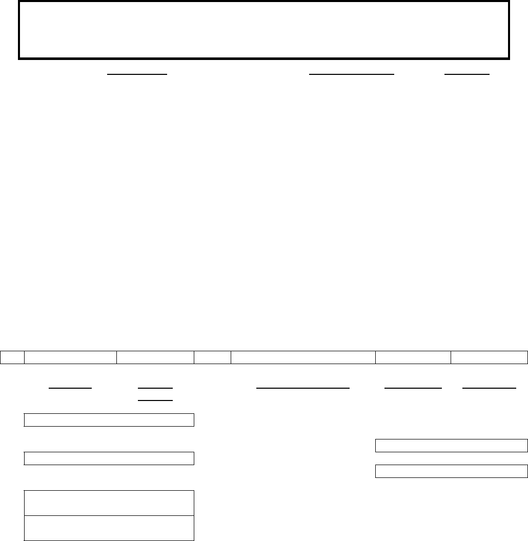
1 MXi CONTROLLER
The MXi control board (Assembly 31C1897) is a single-circuit assembly that provides all of the control functions
required for the MXi series of transmitters on a single circuit board. This board can be configured for a number of
different transmitter types, power levels, transmission standards and options.
Figure 2 MXi Controller
The MXi control board provides local front panel interface via ON/OFF and RESET buttons as well as a graphical
user interface through a front panel LCD assembly with touchpad for user commands. The board implements
controls/status/telemetry for remote control through a rear panel connector that will interface to a typical remote
control systems (such as Moseley or Gentner). An RS232 serial port is also provided to allow the operator to
access the MXi through an external computer (with the appropriate software). The MXi control board has RF
detectors for forward and reflected power and all the circuitry to support AGC/VSWR/Cutback functions. Circuitry
to control and monitor the +50V power supply is also included on this board.
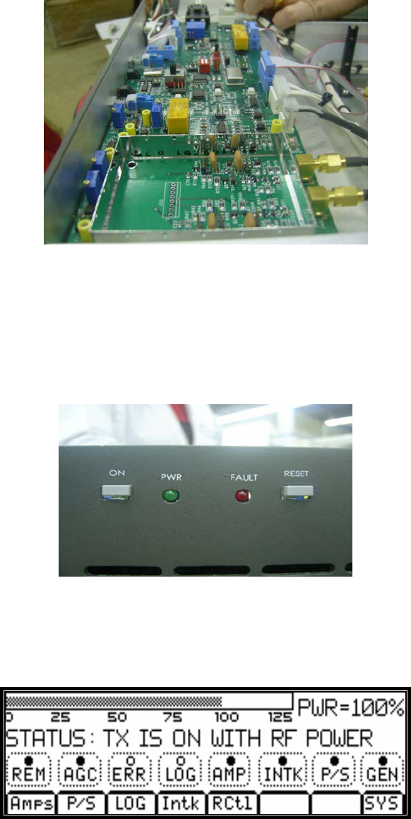
Figure 3 MXi Front Panel
The user interface to the amplifier is accomplished with the front panel LCD that incorporates a touchpad as an
integral part of the unit. The LCD has the capability of displaying a variety of screens, which are selected by the
user via the touchpad. Figure 4 shows the LCD main menu, which shows the present status of the amplifier along
with the selections of submenus.
Figure 4 Main Menu Screen
TSM21Q-365 Rev 0 July 17, 2009 MXiV Dual Pallet Operations and Maintenance 12
MXiV DUAL PALLET OPERATIONS AND MAINTENANCE
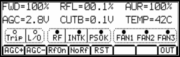
Forward (FWD) and Reflected power (RFL), AURal power, AGC and CUTBack (VSWR) control voltage, as well
as the heatsink TEMPerature (Optional) can be displayed by selecting the AMP submenu as shown in Figure 5.
Figure 5 Amplifier (AMP) Submenu
Similarly, pressing the power supply P/S submenu from the Main Menu displays the power supply voltage and
current consumption as well as its status.
For complete documentation regarding the Controller, see the publication MXi Controller Board.
TSM21Q-365 Rev 0 July 17, 2009 MXiV Dual Pallet Operations and Maintenance 13
MXiV DUAL PALLET OPERATIONS AND MAINTENANCE
2
2.1
AMPLIFIER INSTALLATION AND STARTUP
The MXi Amplifier was fully tested at LARCAN before it was delivered. Under normal circumstances, the
transmitter can be fully operational with minimal setup when turned ON. However, a good practice is to take the
“start from scratch” approach, which means that you should take precautionary measures before the amplifier is
allowed to run at full rated power. These important steps will avoid any catastrophic failures at start-up. The
procedure described is essentially the same approach taken at the factory with a new and untested transmitter.
This also applies if there is a need to completely replace a major sub-assembly in the transmitter.
BEFORE APPLYING AC TO THE UNIT
Pay careful attention to items 1 to 3 before applying AC to the amplifier. These are initial steps that must be
observed and followed for proper and safe operation of the amplifier.
1. Termination
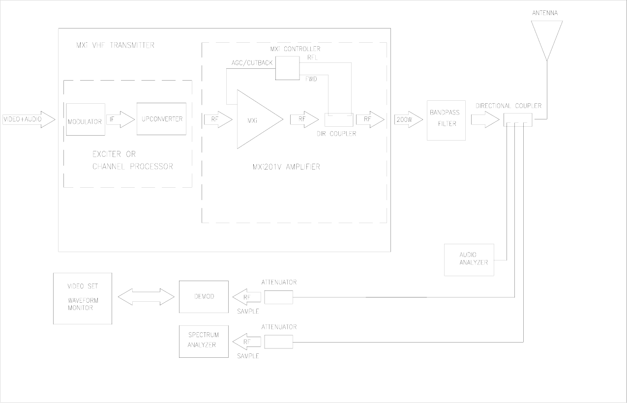
• Ensure that the amplifier is properly terminated with a suitable load. This can be into a dummy load or into
the transmitter output system. A 50 Ohm, 100W load with at least –20dB return loss (1.2 VSWR) is
recommended. Preferably, directional couplers with known coupling levels at the frequency of interest
should be connected at the input and output of the band-pass filter. These points are very useful in
determining absolute power levels and losses and for use as an RF sample for monitoring purposes. See
Figure 14 for a typical transmitter test equipment setup.
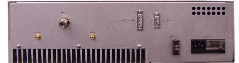
2. Interlocks
Interlocks must be connected to the amplifier to avoid damage to the equipment and to the output
section. Interlock is provided at the INTERLOCK terminal board located on the rear panel. If this interlock
is open, the +50V to the amplifier will shut down, including the cooling fans. DO NOT replace this
interlock with a jumper.
Figure 6 Rear Panel Showing Interlock Terminal Board
3. Power At Minimum
• Initially, the Exciter or Channel Processor’s RF output should be at minimum level. Adjust the OUTPUT
LEVEL control for a minimum output.
2.2 APPLYING AC TO THE UNIT
• Check that the AC voltage available to the amplifier ranges from 90-264VAC. If so, proceed to applying
the power to the AC INPUT of the amplifier
• Once the AC is applied to the unit, the Control Power Supply turns ON and applies +12V to the MXi
Controller.
• Observe that the Power-Up screen is displayed on the LCD, followed by the Main Menu.
TSM21Q-365 Rev 0 July 17, 2009 MXiV Dual Pallet Operations and Maintenance 14
MXiV DUAL PALLET OPERATIONS AND MAINTENANCE
Figure 7 Main Menu
2.3 BEFORE TURNING THE AMPLIFIER ON
From the Main Menu, the status of the amplifier is displayed and shows if the amplifier is ready for operation.
Status legends, when lit, such as the INTK (INTERLOCK), usually signify OK conditions and that the transmitter is
ready to be turned ON.
Check that all of the following conditions are met:
1. EXCITER or Channel Processor is Ready.
• Usually in the application of AC, the Exciter goes through its warm-up sequence. Ensure that it
has done so.
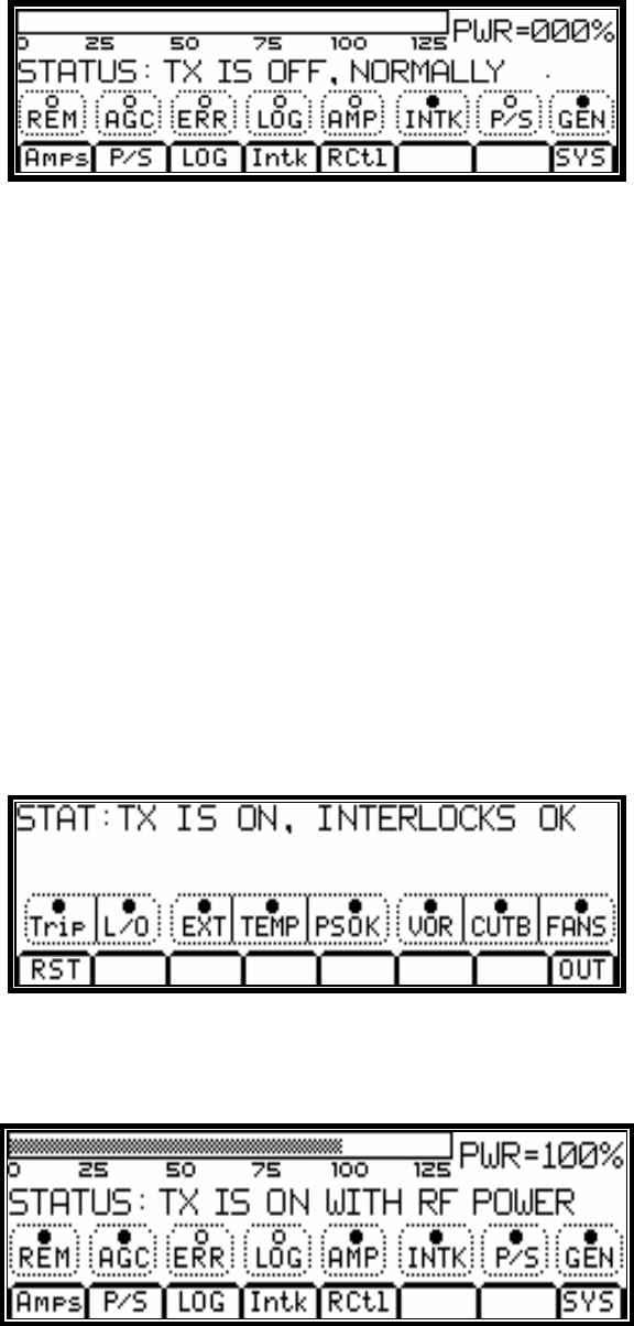
2. POWER METERING is at Zero.
• On the LCD (see Main Menu display in Figure 7), the PWR should be at 000% and the STATUS
should be TX IS OFF, NORMALLY.
3. MXi CONTROLLER is ready.
• If there were prior faults, clear them by pushing the RESET button.
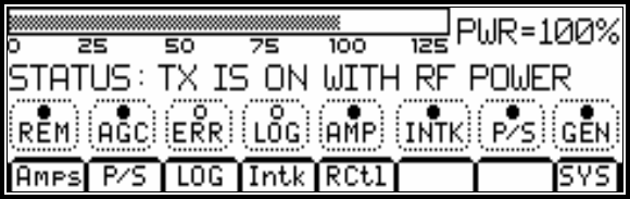
4. INTERLOCKS are closed or OK.
• Interlocks and Status are OK.
Figure 8 Interlocks Status
5. AGC control is DISABLED at this time.
• Push the AGC button on the touchpad so that it is NOT selected.
Figure 9 AGC OFF
6. The Amplifier is in LOCAL mode.
• Push the REM button so that it is NOT lit.
7. The TX is OFF.
TSM21Q-365 Rev 0 July 17, 2009 MXiV Dual Pallet Operations and Maintenance 15
MXiV DUAL PALLET OPERATIONS AND MAINTENANCE
• Push the Front Panel ON/OFF button so that it is NOT pushed in.
2.4
2.4.1
AMPLIFIER ON SEQUENCE
Upon depressing the ON button, the fans start and at the same time the +50V power supply is enabled, thus
applying power to the MXi Amplifier. Since the Exciter or Channel Processor is on hot standby (RF is always
applied), the amplifier normally produces output power immediately.
Turning ON MXi Amplifier
1. Enable amplifier LOCAL operation by pressing the REM touch button such that the REM legend is NOT lit.
• Push the front panel ON button.
• The MXi Amplifier should now be ON.
Figure 10 Transmitter ON
2. Monitor the +50V power supply voltage and current on the LCD. Check that the power supply is operating by
pressing the P/S touch button. The voltage reading should be about 50V and the current should be about
3.0A under Static condition (no RF drive).
ALLOW THE AMPLIFIER SOME WARM-UP TIME!
Only after the transmitter has been ON for approximately 15 minutes should you perform the fine
adjustments. The amplifier must be allowed to reach its operating temperature for stable and consistent
operation. The Power Amplifier in the MXi transmitter is equipped with thermal compensation circuits, which
reduce the output power when the temperature rises. Therefore, the operating temperature must be reached
before adjusting the RF level to its proper level. The amplifier is also equipped with Automatic Gain Control,
primarily designed to prevent the transmitter from overpower or overdrive condition.
3. Increase the RF output by slowly turning the Exciter or Channel Processor output level control.
Stop at about 50% output power indicated on the LCD. At this level, the current should not be more than 6
Amps.
4. If the current is not abnormally high, increase the power to 100%. Again, make note of the PS current reading.
This should not be more than 18 Amps.
5. AGC SETTING: With the AGC still disabled, increase the output power to 110%, using the output level control
in the Exciter or Channel processor. Enable the AGC by pressing the AGC touch button until it lights. Use the
LOWER button to set the power to 100%.
6. With the amplifier fully functional and adjusted to its final setting, record keeping becomes very important.
Record the current, voltage, power, etc. This data can be used as a very valuable troubleshooting tool later.
Below is typical test data pertaining to the MXi amplifier at 100% output power.
TYPICAL DATA read on the LCD
FWD 100% CUTB 0.1V
RFL 00.1% PS VOLTS 50.0V
AGC 1.0V PS CURR 16A
TSM21Q-365 Rev 0 July 17, 2009 MXiV Dual Pallet Operations and Maintenance 16
MXiV DUAL PALLET OPERATIONS AND MAINTENANCE
3
3.1
3.1.1
3.1.2
3.1.3
TEST AND TROUBLESHOOTING
BASIC TROUBLESHOOTING TECHNIQUES
One of the best tools in troubleshooting is knowing what the nominal figures or typical values of the MXi amplifier
when it is at its normal performance. If a fault condition occurs, then you can compare the data taken previously
with the present conditions and come up with a reasonable conclusion about what is at fault.
The following describes some fault conditions and possible solutions.
Amplifier Completely OFF
The MXi amplifier is equipped with a fused AC line filter. Although it rarely happens, abnormal conditions such as
power surges may cause the fuse to blow. A blown AC fuse will completely shutdown the amplifier, including a
complete loss of information on the LCD touchpad. In this case, replacing the fuse will rectify the problem.
No RF Output
• Check for proper power supply voltage.
• Check for potential connector problems causing either no drive to a module pallet (input connector) or VSWR
(output connector) problems.
Output Reduced to 25%
If the output is approximately 25%, a possible cause is a failure of one of the devices in the IPA or the PA
amplifier module. These stages have dual devices so that if one fails the output of that stage will be reduced to
quarter power (25%). A measurement of the current drawn by the amplifier will determine if this condition exists.
The IPA usually draws 1A. If the current is 0.5, then this is the case. Similarly, the if one PA pallet draws either no
current, or significantly less current than the other with no drive condition, then this is also the case.
TSM21Q-365 Rev 0 July 17, 2009 MXiV Dual Pallet Operations and Maintenance 17
MXiV DUAL PALLET OPERATIONS AND MAINTENANCE
4 MAINTENANCE
4.1
4.2
4.3
4.4
Equipment which is regularly and carefully maintained is far less likely to be subject to sudden failure than that
which is operated without regard to basic maintenance requirements. A detailed preventive maintenance program
should be established to ensure that the original efficiency and picture quality is maintained throughout the life of
the equipment. Given reasonable care and attention, the transmitter will provide efficient and reliable service for
many years.
Preventive maintenance techniques do not necessarily involve extensive dismantling of the various assemblies;
on the contrary, this practice is to be discouraged unless a valid reason exists for doing so. Preventive
maintenance is more directed at detailed physical inspection and the general observation of the equipment during
and after operation, to detect the presence of any abnormality, which, if not corrected, might result in operational
failure.
In preparing any maintenance program, the frequency and scope of the inspections must be determined and to a
great degree will be influenced by site location and the station's market parameters and consequently its hours of
operation, equipment configuration, and technical personnel deployment. For example, is the station on the air for
24 hours-a-day? Are there main/standby transmitters and are they attended or unattended?
In general, the following routines should form the basis of any maintenance program.
DAILY
At an attended site, the operator is afforded the opportunity to make frequent checks on the equipment and
thereby increase his/her familiarity with its operation. The transmitter log entries made during these checks would
include all meter readings, also any irregularity in performance or in picture quality, for later analysis. An
unattended site where equipment is operated by remote control and monitored by telemetry and a high quality off-
air receiver or demodulator can also be continuously checked for performance by studio technical personnel.
MONTHLY
In addition to the normal operational tests, thorough physical inspection of every piece of equipment should be
made, with all power turned off. All surfaces should be dusted off or wiped down, terminal boards checked for
loose connections, and all components examined for any evidence of overheating. High-pressure air, not over
20psi, can be used with discretion to dislodge dust from inaccessible places.
SEMI-ANNUALLY AND ANNUALLY
Check all external RF connections for tightness, looking specifically for any discoloration, which might indicate a
loose inner connector, flange or sleeve coupling. Test the passive RF system with a transmission test set or
network analyzer, if one is available, to identify any potential problems with the antenna or line. Inspect and clean
contacts on all switches and contactors; carefully redress contact surfaces if pitted.
Check the operation of all interlocks including patch panel, dummy load, air and thermal switches and emergency
interlocks (if applicable).
TRANSMITTER COOLING SYSTEM
All cooling fans in the transmitter are fitted with sealed bearings requiring no lubrication during the lifetime of the
motor. Access to the blower assembly is via the top of the transmitter.
TSM21Q-365 Rev 0 July 17, 2009 MXiV Dual Pallet Operations and Maintenance 18
MXiV DUAL PALLET OPERATIONS AND MAINTENANCE
5
5.1
SERVICE
The MXi contains few user-serviceable parts; the modular surface-mount design makes module replacement
and/or factory repair the most efficient repair method.
The service most likely to be performed by users is the replacement of the fan array.
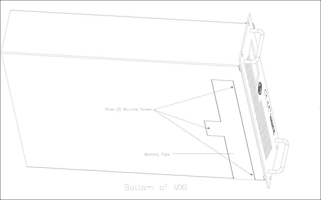
REMOVING THE FAN ARRAY
The MXi fan array consists of four 4” muffin-type fans which are attached to the mounting plate. The mounting
plate is secured to the bottom of the MXi chassis with three Phillips head screws.
Figure 11 Bottom View of MXi
1. Turn the MXi OFF.
2. Disconnect the AC power from the MXi.
3. Slide the MXi partially out from the mounting rack. Important: Ensure that the weight of the MXi is fully
supported.
4. With a Phillips screwdriver, remove the three mounting screws on the underside of the MXi. When
removing the last screw, be sure to hold the mounting plate in place.
5. Remove the mounting plate. The fan array is attached to the mounting plate and comes out with the plate.
TSM21Q-365 Rev 0 July 17, 2009 MXiV Dual Pallet Operations and Maintenance 19
MXiV DUAL PALLET OPERATIONS AND MAINTENANCE
TSM21Q-365 Rev 0 July 17, 2009 MXiV Dual Pallet Operations and Maintenance 20
5.2 R
5.3 R
In the event of a fan failure, LARCAN recommends replacing the entire array, as all fans have a similar lifespan.
1. Remove the fan array as described in Section 5.1.
2. Each of the four fans is attached to the mounting plate via two screw-and-nut assemblies. Remove the
screws and nuts and set aside.
3. Insert and tighten the five mounting screws. Note: Screws only need to be snug; do not overtighten.
2. Slide the new fan array into the MXi. The power connection is aligned so that it connects when the
mounting plate is fully in place.
1. Remove the fan array as described in Section 5.1.
9. Replace fan array into MXi as described in Section 5.1.
8. If necessary, replace the zip tie holding the wires to the fan frame.
7. Re-fasten the two screw-and-nut assemblies holding the fan to the mounting plate.
6. Re-connect the three-pin wiring harness connection.
5. Remove the defective fan and replace with a known good fan of exactly the same dimensions and
specifications.
4. If necessary, carefully cut and remove the zip tie holding the wires to the fan frame.
3. Disconnect the three-pin wiring harness connection by gently sliding it back with a fingernail or small
plastic tool.
EPLACING A SINGLE FAN
EPLACING THE ENTIRE FAN ARRAY
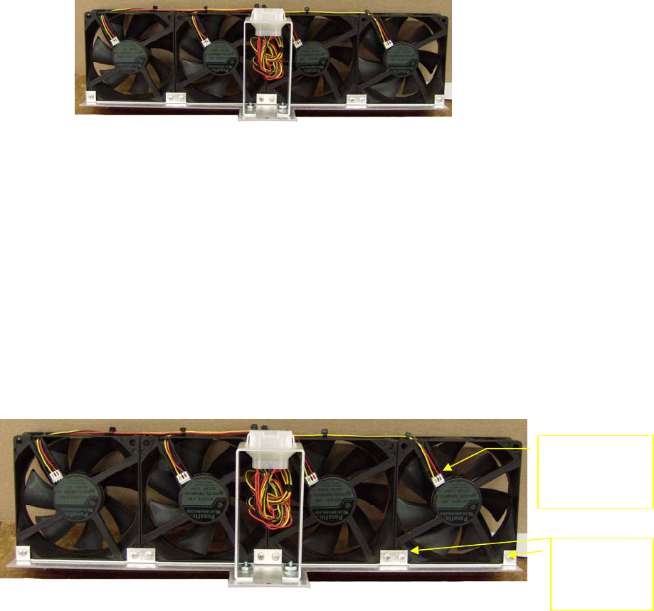
Figure 13 Fan Attachment to Mounting Plate
Figure 12 Fan Array
Three-pin
wiring harness
connector
Screw-and-
nut
assemblies
MXiV DUAL PALLET OPERATIONS AND MAINTENANCE
TSM21Q-365 Rev 0 July 17, 2009 MXiV Dual Pallet Operations and Maintenance 21
6
Figure 14 Test Equipment Setup
TEST EQUIPMENT SETUP
MXi DUAL PALLET OPERATIONS AND MAINTENANCE
7
7.1
7.2
7.3
7.4
7.5
SPECIFICATIONS
Specifications are subject to change without notice.
ELECTRICAL
AC Line Input .....................................................................................................................90 to 264VAC, 50 to 60Hz
Power Consumption, black picture + 10% aural ................................................................................. 500VA (typical)
ENVIRONMENTAL
Ambient Temperature .....................................................................................................0°C to +45°C (0°F to 113°F)
Humidity ..................................................................................................................................................... 0% to 90%
Altitude ............................................................................................................................................. 2286 m (7500 ft.)
COOLING
Four 4” muffin fans push air through the heatsink and through the rear panel perforations.
DIMENSIONS
The Amplifier and Channel Processor chassis are standard 19" rack wide units.
Height
Amplifier........................................................................................................................................5.25" (3RU)
Exciter or Channel Processor.......................................................................................................1.75” (1RU)
Total Height ..................................................................................................................................7.00” (4RU)
Depth is 25" including a 3" allowance for connectors.
SHIPPING WEIGHT
Weight ……………………………….……… .....................................................................Approximately 14kg (31lbs.)
TSM21Q-365 Rev 0 July 17, 2009 MXiV Dual Pallet Operations and Maintenance 22
MXi AMPLIFIER CHASSIS
CONTENTS
1 MXi AMPLIFIER...........................................................................................................................................................24
FIGURES
FIGURE 15 FRONT VIEW OF MXI AMPLIFIER..............................................................................................................................24
FIGURE 16 REAR VIEW OF MXI AMPLIFIER................................................................................................................................24
FIGURE 17MXI FAN ARRAY.......................................................................................................................................................25
FIGURE 18 MXI HEATSINK ASSEMBLY .......................................................................................................................................25
TSM21Q-365 Rev 0 July 17, 2009 MXi Dual Pallet Amplifier Chassis 23
MXi AMPLIFIER CHASSIS
1 MXi VHF AMPLIFIER
The MXi VHF Amplifier Chassis Assembly consists of a standard 19" rack mountable 5.25" (3RU) enclosure
containing the amplifier heatsink assembly, a fan array assembly consisting of four DC cooling fans, a controller
board with built-in RF detectors, and a front panel consisting of ON/OFF, RESET switches and an
LCD/Touchpad, and a rear panel assembly with connectors for interfacing to external equipment. A dual output
DC power supply for powering the amplifier, the controller and the cooling fans is also housed in this enclosure.
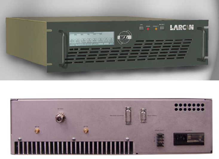
Figure 15 is a front view of the MXi101V amplifier, showing the LCD Touchpad, ON/OFF switch, Status PWR
(Green) and FAULT (Red) LEDs, and RESET switch.
Figure 15 Front View of MXi Amplifier
Figure 16 Rear View of MXi Amplifier
The rear of the MXi AMPLIFIER has the following connectors (from left to right):
• RF IN SMA connector-
• RF OUT N connector
• RF TP SMA connector – RF sample
• REMOTE CONTROL 15-pin D-shell connector
• RS232 SERIAL nine-pin connector
• INTERLOCK terminal board
• AC INPUT
The MXi is classified as a broadband amplifier, thus it is operational to cover the entire VHF television spectrum in
three bands comprising ATSC channels 2 through 4, 5 through 6 and channels 7 through 13.
Controlled DC power to the amplifier assembly comes from the high efficiency 1000W switching power supply via
a two-pin connector, J4 of the MXi Controller Board. Regulated DC of +50V from the switching power supply is
the B+ voltage to the amplifier heatsink assembly. The second auxiliary output of the power supply is +12VDC,
which is used for powering the controller and the cooling fans.
The heatsink cooling fans are the +12DC, 4-inch muffin model. Typically, they come ON at the same time B+ is
applied to the power amplifier. It is connected to the controller PC board connector, J8. As built, the cooling fans
TSM21Q-365 Rev 0 July 17, 2009 MXi Dual Pallet Amplifier Chassis 24
MXi AMPLIFIER CHASSIS
push air from the front panel through the heatsink and through the perforations in the rear panel. This assembly is
located underneath the MXi Controller board.
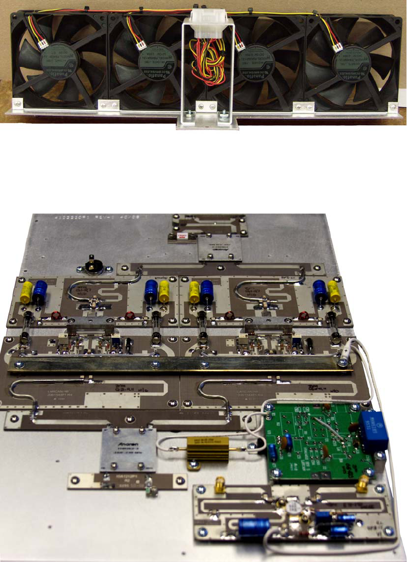
Figure 17 MXi Fan Array
A thermal switch is mounted on the heatsink where the operating temperature is sensed. If this temperature
increases beyond the trip point of the thermal switch, which is about 60°C, its contact opens and breaks the
interlocking circuit of the MXi amplifier. The interlock circuit ultimately controls the power supply to the power
amplifier and therefore shuts down and remains OFF until the heatsink cools down to about 50°C.
Figure 18 MXi Heatsink Assembly
A directional coupler is also mounted on the heatsink and provides forward and reflected RF signals to the
controller. These RF samples are detected and processed on the MXi amplifier controller to provide DC outputs
corresponding to these signals. They are then used for AGC, VSWR supervision and also for providing digital
metering available on the front panel LCD touchpad.
TSM21Q-365 Rev 0 July 17, 2009 MXi Dual Pallet Amplifier Chassis 25
POWER AMPLIFIER HEATSINK ASSEMBLY
TSM21Q-365 Rev 0 July 17, 2009 June 2009 26
CONTENTS
1 FUNCTIONAL DESCRIPTION:...................................................................................................................................27
2 RF PREAMPLIFIER ......................................................................................................................................................27
3 POWER AMPLIFIER:...................................................................................................................................................27
4 ADJUSTMENT OF BIAS VOLTAGE TO ESTABLISH PROPER QUIESCENT FET BIAS CURRENT:..........28
5 LOW POWER SWEEP AMPLIFIERS.........................................................................................................................29
FIGURES
FIGURE 19 MODULE SWEEP SETUP .........................................................................................................................................29
POWER AMPLIFIER HEATSINK ASSEMBLY
TSM21Q-365 Rev 0 July 17, 2009 PA Assembly 27
1 FUNCTIONAL DESCRIPTION:
The Power Amplifier heatsink assembly consists of a preamplifier driving a four-way power splitter, four 250W
FET amplifiers, a four-way power combiner. A full-size heatsink provides the cooling for the active devices. It is
designed for High Band 174 - 230 MHz television systems, and provides power gain of approximately 15 - 16 dB,
with 1 kW peak sync visual or 600 W aural output. The module can provide upwards of 200W of average digital
power when used with appropriate predistortion.
2 RF PREAMPLIFIER
High Band preamps 10A1453G1, used in higher powered transmitter service, have a type MWA130 instead of an
MWA330 for U4. Specified gain of an MWA130 is approximately 12dB.
At the output of U2, a match to 50Ω is provided by C12 and the device lead inductance. These together create a
low pass matching network in boards where a type CA2885 amplifier is used; conversely a type MHW6185 device
characteristics give it a wideband match to 50Ω therefore no special output matching is necessary, and C12 is not
present.
U3 is a voltage regulator providing +24 V to the preamplifier stage(s).
3 POWER AMPLIFIER:
.
The output amplifier consists of a single, source grounded, N-channel, insulated gate Field Effect Transistors (FETs)
packaged in a single case and operating Class AB in a push-pull configuration. Because these FETs are
"enhancement mode" devices, they require a positive gate-to-source bias voltage on each gate to cause
source-drain conduction. The quiescent Class AB idling bias current is set independently for each half. The
threshold gate voltage required to produce this idling current is typically may vary between 2V and 5V. Gate voltage
thresholds in FETs also are temperature sensitive, so thermal compensation is provided by thermistor elements RT1
and RT2. Bias current is set to 500mA per half of the device for analog operation and 750mA per half for digital
operation.
Gate bias is supplied from an adjustable voltage divider from the +39 V regulated bias rail. Resistors R1, R2, R3,
R4 provide gate bias for one half of the amplifier; R5, R6, R7, R8 provide bias for the other half.
The RF input signal is applied to balun T1/L1 to provide two signals 180° out of phase. These signals are stepped
down to match the low input impedance of the FET through a double L-π-network consisting of C1, C2, L2, L3, C7,
and the gate capacitances of the FET, and then applied to the gates. The gate input impedance at the operating
frequency is very low by comparison with the values of R3 and R6, so these resistors have little or no effect at RF.
R3 and R6 provide a DC path for bias, and provide loading at lower frequencies in order to assist in maintaining
amplifier stability. The choice of C4 and C5 values, and their internal equivalent series inductances, also ensures
effective bypassing at all frequencies.
The output matching double π-network, consisting of inductors L4 thru L10, and capacitances C12 thru C15, tunes
out the FET drain capacitance and transforms the very low output impedance of the FET to 12.5 ohms. The two
antiphase output signals, Push and Pull, are combined in balun T2, L11.
DC is applied to the drains through L4, L5 for the first half, and L6, L7 for the other half. L5 and L6 are also short
sections of microstrip transmission line which transform the apparent RF impedances of L4 and L7 to more effective
values as seen by the FET. RF and lower frequencies are bypassed with C3, C8, C9, and C6, C10, C11.
These groups of capacitors are selected in value and for their internal equivalent series inductances so that they will
be an effective bypass at all frequencies of interest including video, to assist in maintaining amplifier stability.
Towards this objective of stability: inductance L9, in addition to resonating with the FET output capacitance in the
POWER AMPLIFIER HEATSINK ASSEMBLY
TSM21Q-365 Rev 0 July 17, 2009 PA Assembly 28
operating frequency band, also is equivalent to a dead short at lower frequencies where it loads the device so
heavily so that the stage will not become unstable.
Note that fuses are provided for the voltage supplied to the FET drain connections. The intent of these fuses is to
protect the surrounding circuitry in the event of a device failure. The normal failure mode of active devices such as
these is short-circuit, and the fuse will blow in this case, isolating the defective device from the rest of the module
and transmitter power supply, allowing the remaining devices to keep operating normally. A blown fuse can serve
as a valuable troubleshooting aid, when trying to identify failed devices.
4 ADJUSTMENT OF BIAS VOLTAGE TO ESTABLISH PROPER QUIESCENT FET
BIAS CURRENT:
Important: 50 Ω input and output terminations are necessary to achieve consistent results and prevent damage
to the devices when testing modules. Supplemental cooling is not required when performing bias adjustments or
low power sweep of the PA modules.
1. Remove all fuses from the module to be tested. (There are 8 fuses in total).
2. Adjust all bias pots to maximum resistance, for minimum bias voltage. (Again, there are 8).
3. 3.Use a clip lead to short the junction of C5, R6, and R7 to ground. This shuts off side B of the amplifier so
it will not interfere (thru L9) with measurement of quiescent current from side A.
4. Terminate the RF input and output into a 50 Ω load.
5. Apply +50VDC from the front panel test point on the transmitter, through an ammeter, to the positive
copper bus bar, and its negative to chassis. Caution: Observe polarity!
6. Check the voltage on the bias terminals, it should be 39 V ±2 V. (The bias terminals are connected
together via insulated bus wire).
7. Read the current drawn by the VSWR board and bias regulator. Next, install a fuse in side A (nearest the
panel) of amplifier #1; adjust the corresponding bias pot for a 500 mA increase in the power supply
current; this increase corresponds to an idling bias current of 0.5 A. Remove the fuse. Remove the side
B bias short and place it on side A at the junction of C6, R2, R3 and R9. Place the fuse in side B. Adjust
the side B bias pot for the proper current.
8. Move the fuse to the remaining fuse holders, one at a time, and adjust each companion bias
potentiometer in the same manner for the proper bias current.
9. Install remaining fuses and remove the bias short after all bias adjustments have been made.
POWER AMPLIFIER HEATSINK ASSEMBLY
TSM21Q-365 Rev 0 July 17, 2009 PA Assembly 29
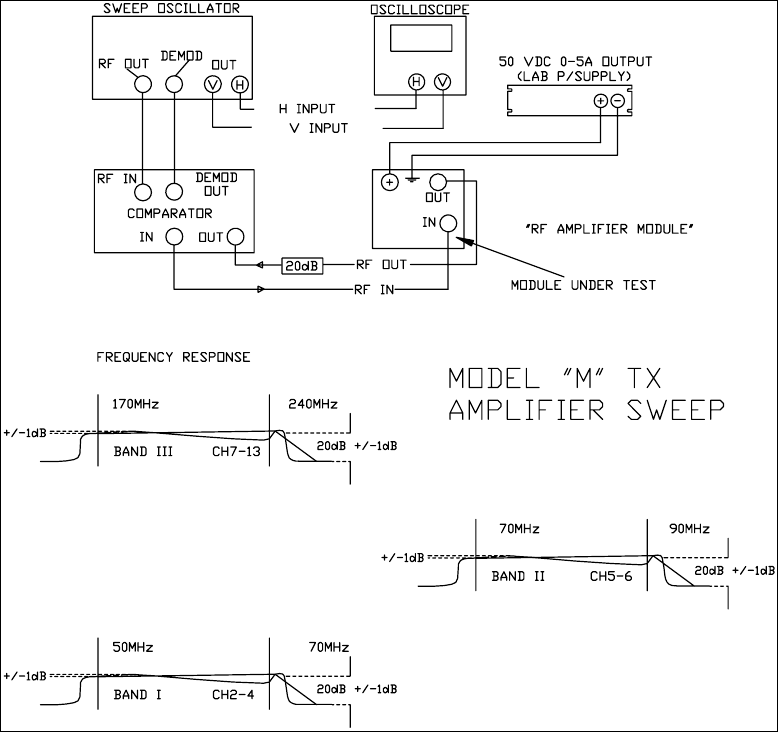
6 LOW POWER SWEEP AMPLIFIERS
Note: Low power sweep of PA modules should not be required under normal circumstances – even when
replacing FET devices. There are no tuning adjustments on these modules.
1. Ensure that terminations are in place in the test setup. All modules require 50 Ω source and load
impedances to prevent damage and for consistent results during testing.
2. Connect the module to a sweep system, typically as shown in Figure 1. The sweep generator should be
adjusted to give a linear sweep from 160 to 240 MHz so that all of High Band or Band III is swept, with a
small amount of out-of-band signal on both ends.
3. Connect the lab power supply +50 V to the positive supply bus bar, and the negative to the chassis of the
amplifier. The current should be limited to 7 or 8 A for this test. Caution: observe polarity!
4. With the power supply switched on, the current drawn should be not more than the bias current for all the
devices together - about 4 amperes (8 x 0.5 A) for the PA module.
The swept in-band frequency response, for High Band modules, should be essentially flat within ±1 dB as shown
in Figure 1, with gain approximately 15 to 16dB.
Figure 19 Module Sweep Setup
MXi 50V 1KW POWER SUPPLY
CONTENTS
1 MXi POWER SUPPLY LAR1000-32-P5337.................................................................................................................31
2 POWER SUPPLY DATA SHEET REPRINT ..............................................................................................................33
FIGURES
FIGURE 20 MXI 1000W POWER SUPPLY ....................................................................................................................................31
FIGURE 21 12-TERMINAL INTERFACE BOARD ............................................................................................................................31
TSM21Q-365 Rev 0 July 17, 2009 MXi 1kW Power Supply 30
MXi 50V 1KW POWER SUPPLY
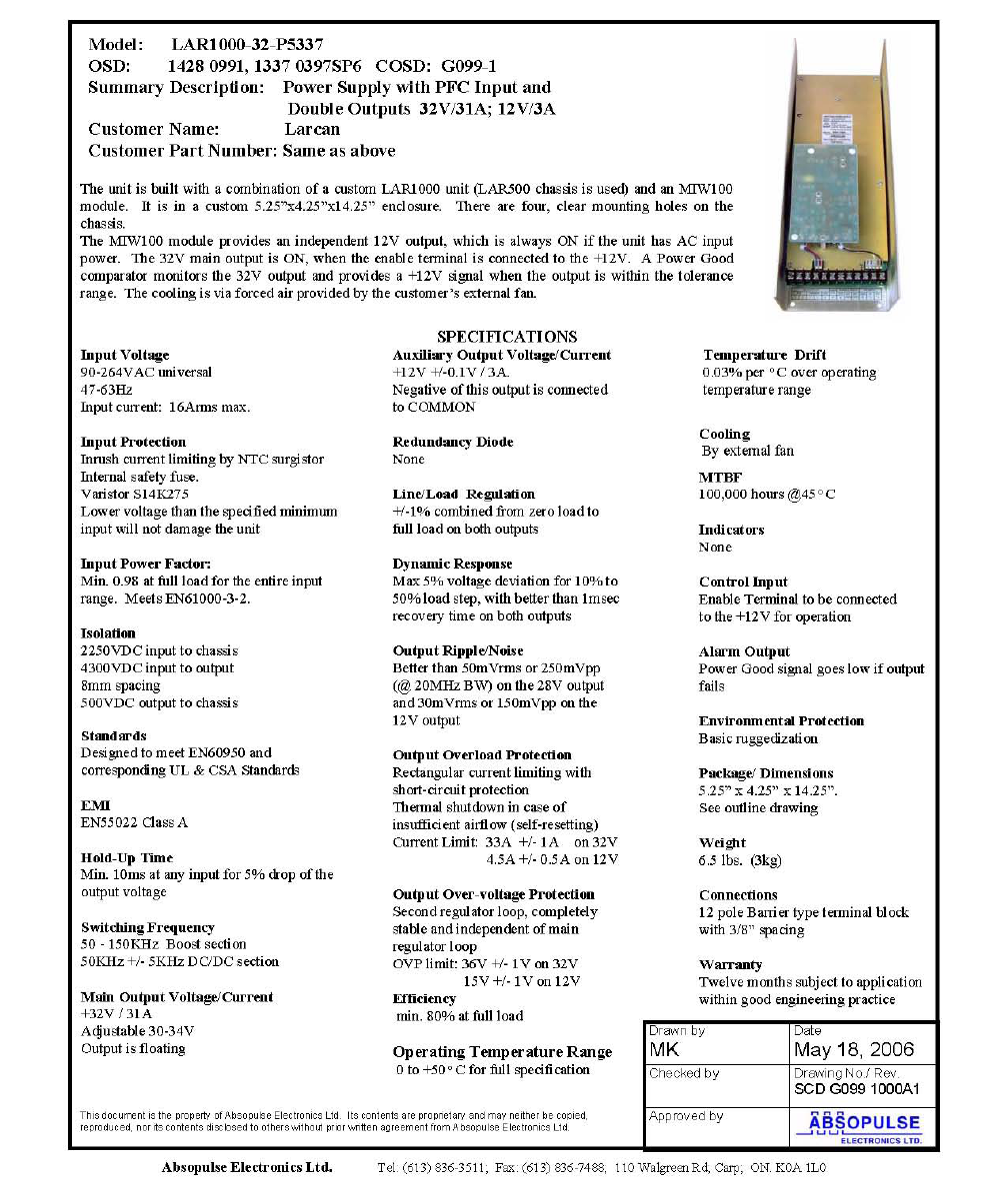
1 MXi POWER SUPPLY LAR1000-50-P5337
The LAR1000-50-P5337 power supply used in the MXi Dual Pallet VHF amplifier is a free-standing, power factor
corrected 1000W unit. It has the capability to deliver up to 20A when the power supply output is set to +50VDC.
The design of this unit results in a highly efficient power supply ideal for the MXi dual pallet power level. This unit
also contains an internal auxiliary 12VDC power supply rated at 3A which is used to provide power to the MXi
Controller board as well as supplying power to the cooling fans. This auxiliary power supply provides +12VDC
output as long as the main AC input is present.
Figure 20 MXi 1000W Power Supply
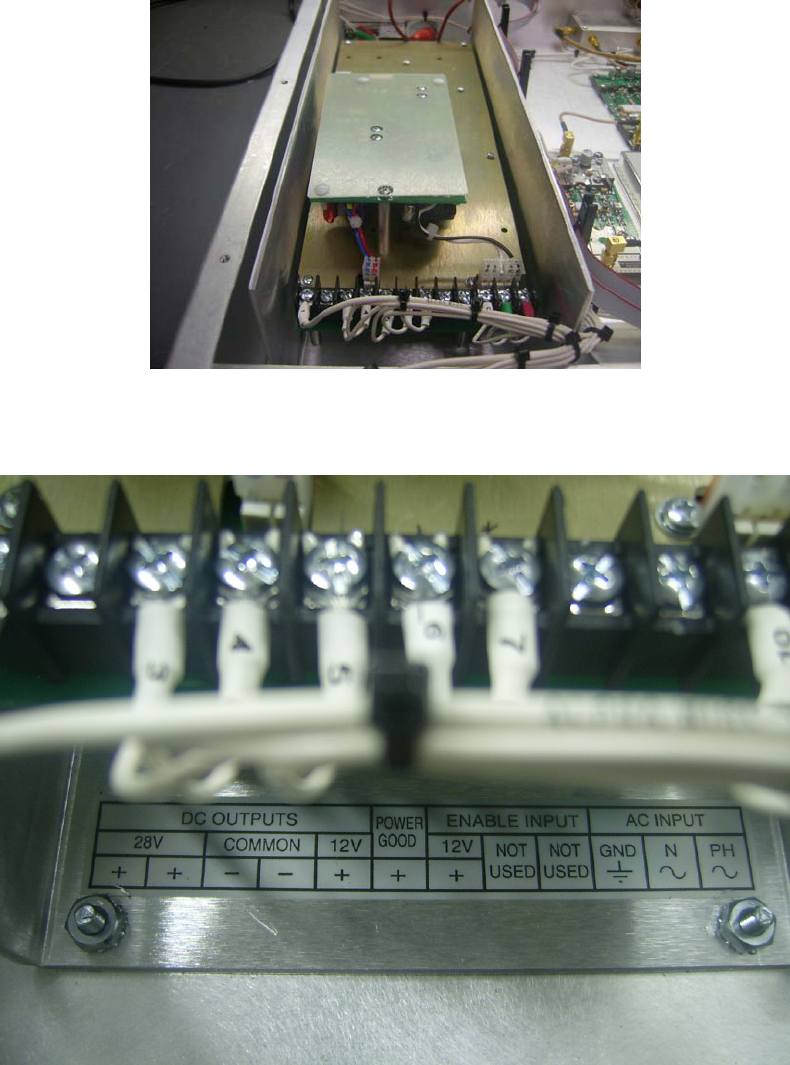
A 12-terminal interface board is used in the power supply for interfacing to various sub-assemblies in the MXi
enclosure. The following describes the function of each terminal.
Figure 21 12-Terminal Interface Board
TSM21Q-365 Rev 0 July 17, 2009 MXi101V 31

MXi 50V 1KW POWER SUPPLY
TERMINAL/DESCRIPTION FUNCTION
1. +50VDC OUTPUT First of two +50VDC outputs of the power supply
2. +50VDC OUTPUT Second of two +50VDC outputs of the power supply
3. COMMON (–) return of the 50V and 12V power supply
4. COMMON (–) return of the 50V and 12V power supply
5. +12VDC OUTPUT +12VDC for powering the MXi controller
6. POWER GOOD A High (+12V) is measured here if the +50V power supply is OK
7. +12V ENABLE INPUT If +12V is applied here, it will turn ON the +50VDC power supply.
This enable signal comes from the MXi controller board provided the interlocks
are closed and there are no fault conditions.
8. NOT USED
9. NOT USED
10. GND AC GND
11. N AC Neutral
12. PH AC Phase (Line)
TSM21Q-365 Rev 0 July 17, 2009 MXi101V 32
MXi 50V 1KW POWER SUPPLY
2 POWER SUPPLY DATA SHEET REPRINT
The following is a reprint of the LAR1000-50-P5337 switching power supply data sheet, with permission from
Absopulse Electronics Ltd.
TSM21Q-365 Rev 0 July 17, 2009 MXi101V 33
MXi 50V 1KW POWER SUPPLY
TSM21Q-365 Rev 0 July 17, 2009 MXi101V 34