Laserline S p A EPS4003RF-RX ELECTRONIC PARKING SYSTEM - RECEIVER User Manual F istruzioni p65 ISTRUZIONI LA
Laserline S.p.A. ELECTRONIC PARKING SYSTEM - RECEIVER F istruzioni p65 ISTRUZIONI LA
User Manual
L'installazione di questo prodotto deve essere
effettuata da personale competente e qualificato
EPS
Electronic Parking System
- Radio -
This product must be installed by
skilled and qualified personnel
IISTRUZIONI DI MONTAGGIO
GB FITTING INSTRUCTION
ISEPSRF.p6511/05/2005, 17.181
2
Il prodotto è formato dalle seguenti parti:
- sensori ad ultrasuoni: emettono brevi impulsi ad ultrasuoni i quali
rimbalzano ogni volta che incontrano degli ostacoli e attraverso una
trasmissione via radio viene trasferita l’informazione al ricevitore posto all’interno
del veicolo; a seconda del modello, i sensori sono già montati sul profilo pastico
o forniti da installare sul paraurti della vettura;
- trasmettitore: è la centralina alla quale sono collegati i sensori e che trasmette
le informazione al ricevitore. Questa centralina è incorporata nel profilo plastico
o separata da fissare nel portabagagli.
- ricevitore: decodifica l’informazione e segnala la presenza di tali ostacoli al
conducente attraverso una serie di ‘beeps’ tramite un altoparlante (è possibile
scegliere il volume di segnalazione: alto-medio-basso). Ogni centralina ha un
codice univoco, in questo modo ogni ricevitore comunica solo con il profilo ad esso
abbinato. E' posizionato all'interno del veicolo, collegato attraverso la presa
accendisigari oppure tramite cavo all'impianto elettrico.
DESCRIZIONE DEL FUNZIONAMENTO
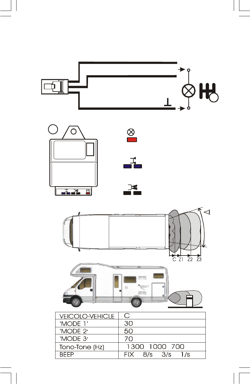
Per indicare la corretta attivazione del sistema all’inserimento della retromarcia
verrà emesso un breve ‘beep’, dopodichè il dispositivo inizierà la rilevazione degli
ostacoli a cui il veicolo si avvicinerà. Con l’avvicinarsi all’ostacolo, la segnalazione
acustica diventerà più frequente, fino a diventare continua per ostacoli posti nella
zona C (vedi tabella e raffigurazione).
IMPOSTAZIONI
Tramite il pulsante posto sul ricevitore è possibile variare le distanze di rilevamento
degli ostacoli, come indicate nella tabella, ed attivare la PROCEDURA DI
AUTOAPPRENDIMENTO. Inizialmente è impostato ‘MODE 1’; premendo il pulsan-
te una volta si accenderà il LED ARANCIONE per 3 secondi e si passerà a ‘MODE
2’, premendo ancora una volta il pulsante si accenderà il LED ROSSO per 3 secondi
e si passerà a ‘MODE 3’. Premendo ancora il pulsante si accenderà il LED VERDE
per 3 secondi e si ritornerà a ‘MODE 1’, in modo sempre ciclico. Il LED verde
lampeggerà ogni volta che una corretta trasmissione viene inviata dal trasmettitore. Se
il LED verde lampeggia ma non si sente nessun tono all'inserimento della retromarcia,
sarà necessario rieseguire la “PROCEDURA DI AUTOAPPRENDIMENTO”.
NOTA: occorre in ogni caso guardare dietro al veicolo mentre si manovra,
piccoli ostacoli o oggetti di bassa capacità di riflessione non possono essere
rilevati dal sistema.
I
PROCEDURA DI AUTOAPPRENDIMENTO
Per cancellare il codice univoco premere il pulsante per almeno 5 sec.; adesso la
memoria del ricevitore è vuota e il LED rosso lampeggia. Quando il LED rosso del
ricevitore lampeggia, collegare l’alimentazione al profilo plastico (o inserire la
retromarcia se il profilo plastico è già installato sul veicolo). Dopo pochi secondi
il LED verde lampeggerà e il nuovo codice univoco del profilo sarà memorizzato nel
ricevitore.
ISTRUZIONI DI MONTAGGIO
1 - RICEVITORE: connettere alla presa accendisigari del veicolo o collegare i cavi
all'impianto elettrico del veicolo; il LED giallo sarà acceso fisso, per indicare il corretto
collegamento e nessun errore rilevato dall’unità. Se un codice univoco del profilo ad
ultrasuoni è memorizzato correttamente nel ricevitore, il LED rosso/verde sarà spento.
Mentre nel caso in cui lampeggi il LED rosso, si dovrà seguire la PROCEDURA DI
AUTOAPPRENDIMENTO.
2 - PROFILO AD ULTRASUONI: installare nella parte posteriore del veicolo, ad una
distanza minima di 50cm dal livello stradale. I sensori posti su di esso devono essere
perpendicolari rispetto al suolo, eventualmente si devono utilizzare le staffe fornite nel kit.
SENSORI AD ULTRASUONI
L’unità centrale deve essere collocata nel portabagagli posteriore. I sensori ultrasuono
verranno fissati sul paraurti posteriore in accordo alle quote riportate nella illustrazione.
ISEPSRF.p6511/05/2005, 17.182

3
2INSTALLAZIONE DEI SENSORI E DEI LORO SUPPORTI
Versione standard: pulire bene lo spazio relativo ai supporti autoadesivi sul
paraurti applicando uno strato di Primer 3M 4298 UV (ATTENZIONE! FACILMEN-
TE INFIAMMABILE, NOCIVO PER INALAZIONE E CONTATTO) lasciandolo
asciugare per almeno 90 secondi. Inserire i sensori nei relativi supporti, rimuovere
il foglio di copertura dei supporti autoadesivi; inserire i supporti con i sensori nei
fori effettuati nel paraurti e premere con forza le alette laterali. Una tenuta
ottimale del supporto avverrà dopo 1 ora dall'installazione.
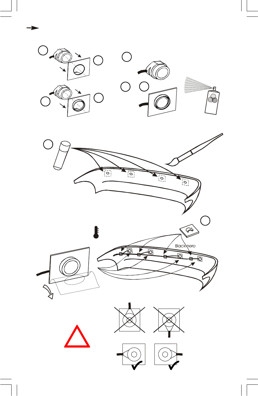
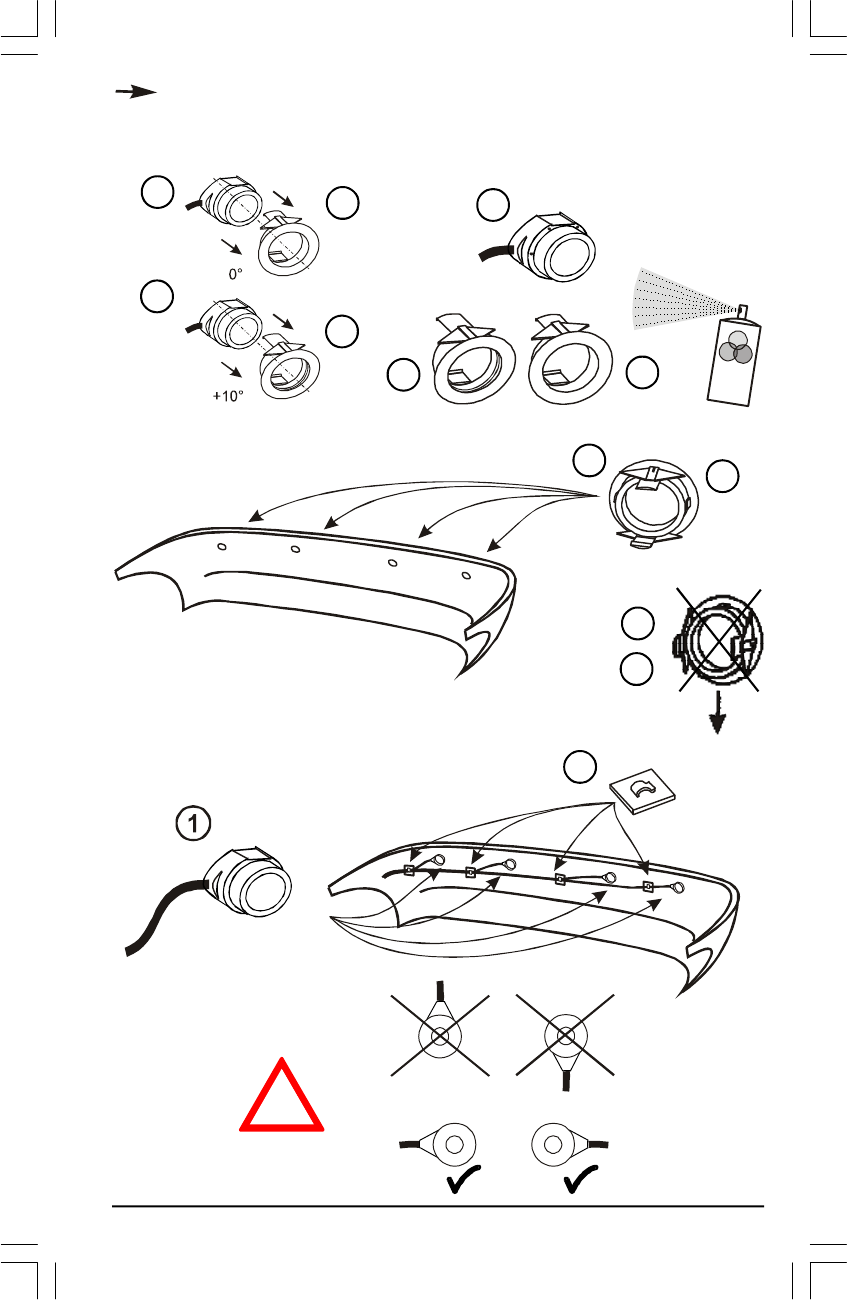
Versione con gasket: inserire i supporti per i sensori (normali o angolari, a seconda
della forma dei paraurti) nei fori effettuati, mantenendo le linguette di fissaggio
degli stessi in posizione corretta (vedi illustrazione).Inserire i sensori posteriori nei
relativi supporti, arrivando al completo incastro negli stessi.
IMPORTANTE!: orientare i sensori in modo che il cablaggio sia orizzontale.
NEL CASO DI INSTALLAZIONE DEI SENSORI SU PARAURTI IN METALLO,
UTILIZZARE L’INSERTO art. PPADI-1 (optional).
Fissare in modo appropriato sul paraurti i cavi dei sensori utilizzando le apposite
fascette con i supporti autoadesivi forniti nel kit.
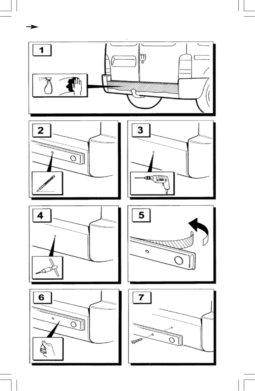
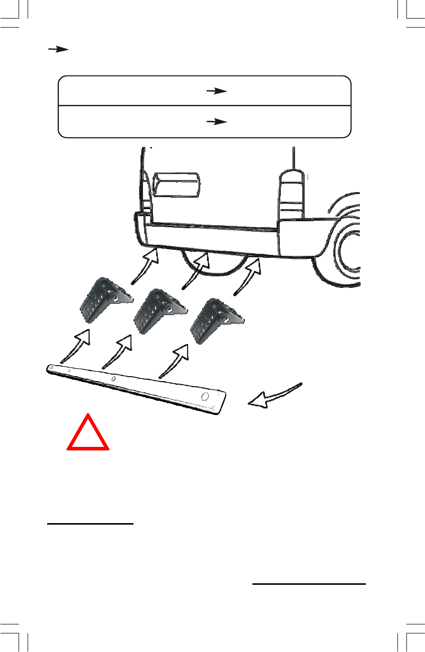
B) Contrassegnare i centri dei fori come da illustrazione, così che siano ad
all’altezza minima dal suolo stradale. Le distanze vengono misurate dal centro
del paraurti lungo la sua superficie arrotondata.
C) Togliere il paraurti posteriore o le “CRASH STRIP”.
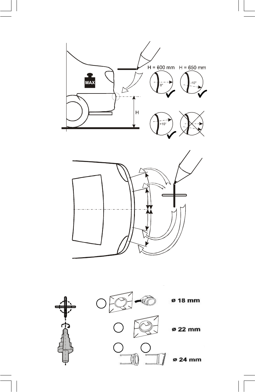
D) Forare con cura creando fori di un diametro di 18mm negli spazi contrasse-
gnati per la versione standard, 22mm se si utilizzano gli inserti angolari,
24mm per la versione gasket.
montaggio dei sensori all’interno del paraurti del veicolo. Se possibile, è preferibile
montare i sensori sulle striscie in gomma dei paraurti, dette anche “CRASH STRIP”.
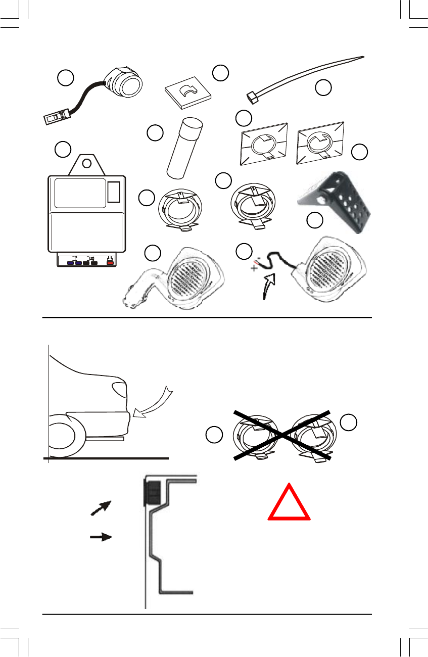
1FORATURA DEL PARAURTI
A) Nelle illustrazioni vengono mostrate le condizioni e le distanze ottimali per il
The product consist of these parts:
- ultrasound sensors: detect the obstacles and send the information,
through radio transmission, at the receiver inside the vehicle; these
sensors are installed on the rear bumper of the vehicle or in the plastic profile;
- transmitter: the sensors are connected to this unit and it transmit the informations
to the receiver. This unit is inserted in the plastic profile or separated to fix in the
boot of the vehicle.
- receiver: with speaker and LED's is connect in the cigarette lighter inside the
vehicle through the plug or with the wires to the electrical system in the car. It decode
the informations and signalling the obstacles at the user with the speaker (a slide
switch provide to select the volume of the speaker: high-average-low). Any central
unit have a unique address, in this way the communication is point to point (one
receiver can get only one ultrasound set).
DESCRIPTION OF THE FUNCTION
The correct activation of the system, when you insert the reverse gear will be
signalled by short “beeps”, after the sensors will start to detect the obstacles.
Further closing the obstacle, the sensor will increase the rate of the “beeps” up to
zone C (see picture this the correct distance) after which the acoustic signalling will
be continous till the reverse gear will maintain selected.
GB
SETTING AND LEARNING PROCEDURE
Through the button in the receiver is possible to vary the distances of detecting
obstacles, as indicated in the table. Initially ‘MODE 1’ is set up; pressing the button
once the ORANGE LED for 3 seconds is ON and will pass to ‘MODE 2’, pressing
once again the button the RED LED for 3 second will be ON and it will be passed
to ‘MODE 3’. Still pressing the button, the GREEN LED for 3 second will be ON and
it will be returned to ‘MODE 1’, always cyclical way. The green LED blinking every
time a correct transmission is received (the receiver is linked with the transmitter).
ISEPSRF.p6511/05/2005, 17.183

4
2 INSTALLATION OF THE SENSORS (STANDARD OR WITH GASKET)
The distribution of the ultrasound sensors has been shown on the illustration.
STANDARD VERSION: clean the area around the holes where the sticky pads will
mount to the bumpers and apply a thin layer of Primer 3M 4298 UV (ATTENTION!
PRIMER IS EXTREMELY FLAMMABLE, VAPOR HARMFUL MAY CAUSE EYE AND
SKIN IRRITATION). Insert sensors into the holders, normal or angle according to
the type of holder that you are using fits over the lock taps to the front of holders.
Remove the covering foil from the self-sticky pads; insert sensors into the appropriate
holes ensuring cable exits horizontaly from sensors and press down on sticky pads
to ensure a good adhesion to the bumper.
GASKET VERSION: insert gaskets for the sensors (normal or angle, see bumpers
construction) into the holes, look the correct position in the illustration.
Fix the cables appropriately inside the bumpers with the enclosed self-sticking
cable holders and/or with cable ties. Route the rear sensors cables into the boot (use
the entry hole for the towing facility, rear lamp loom ect). Ensure cable entry
positions are protected from external events, high-voltage coil and sources of heat.
IF YOU FIT THE SENSOR ON A METAL BUMPER YOU MUST USE THE ADAPTER
ART. PPADI-1 (OPTIONAL).
1 DRILLING OF THE HOLES IN THE BUMPER
A) The perfect positions for fitting the sensors in the cars bumper are shown on the
illustrations.
B) Mark the centres of the holes, as on the illustration, so that they are at the
determined height above the road. The separating distances are measured from the
centre of the bumper.
C) Remove the bumpers or the “Crash Strips”.
D) Carefully drill the holes to a diameter of 18mm for standard version, drill holes
of 22mm diameter if you use the standard version with angle holders, drill holes
of 24mm for gasket version.
LEARNING PROCEDURE
To delete the unique code press the push-button at least 5 sec.; now the memory
of the receiver is empty and when you reconnect the power supply the red LED
blinking. When the red LED in the receiver blinking just connect power supply at the
ultrasound profile (or engage the rear gear if the profile is ready installed on the
vehicle); after a few seconds the green LED blink and the unique code of the profile
is stored in the memory of the receiver.
CONNECTIONS
1 - RECEIVER: simply connect to the cigarette lighter plug; when the plug is powered
the yellow LED is ON (indicate that the power is OK and no errors detect from this unit).
If a unique code of the ultrasound profile is ready stored in the receiver the red/green
LED is OFF, otherwise the red LED blinking (see LEARNING PROCEDURE).
2 - ULTRASOUND PROFILE: install on the back side of the trailer, it will be 50mm at
minimum from the ground, eventually use the iron brackets incluse in the kit.
ULTRASOUND SENSORS
The central unit must be fix in the boot of the vehicle while the ultrasound sensors
must be fix in the rear bumper according the distances show in the illustration.
If the green LED blinking and no one tone is emetted when the reverse gear is
inserted, is necessary to do the “LEARNING PROCEDURE”.
NOTE: you must always visually monitor the space around the vehicle even
with the BACK SONAR fitted. It will not be able to detect any obstacle: small
obstacles are subject to a low rebounding capacity and may not be detected by
the system. The sensors will fully recover its detecting ability as soon as the
vehicle moves away from any obstacle within that area.
ISEPSRF.p6511/05/2005, 17.184
5
PRIMER
3M 4298UV
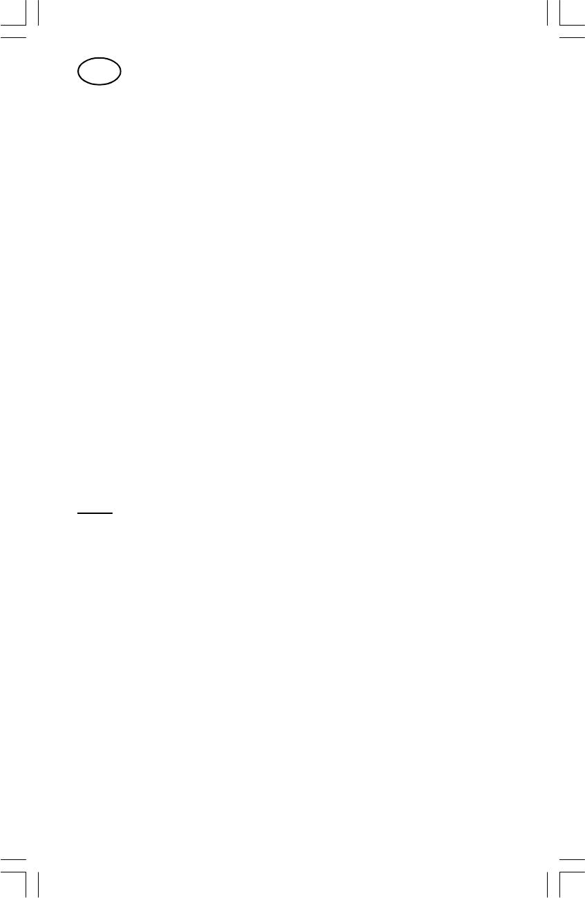
COMPOSIZIONE DEL KIT - SET CONTENTS
12
3
4
5
8
6
9
7
AVVERTENZE - WARNING
NEL CASO DI INSTALLAZIONE DEI SENSORI SU
PARAURTI IN METALLO, UTILIZZARE L’INSERTO
ART. PPADI-1 (OPTIONAL).
IF YOU FIT THE SENSOR ON A METAL
BUMPER YOU MUST USE THE ADAPTER ART.
PPADI-1 (OPTIONAL).
9
8
OK
NO! FARE ATTENZIONE ALLA PRESENZA DEL
LONGHERONE IN FERRO DIETRO IL
PARAURTI DEL VEICOLO
MAKE ATTENTION TO THE PRESENCE
OF THE STRENGTHENING BAR BEHIND
THE BUMPER OF THE VEHICLE
SENSORE
SENSOR
10
11 12
CBS-4 RF
12/24V= CC
1
3
2
4
!
FILO-WIRE: 1,5m
ISEPSRF.p6511/05/2005, 17.195
6
FORATURA PARAURTI
DRILLING OF THE HOLES IN THE BUMPER
INSTALLAZIONE DEI SENSORI - SENSORS INSTALLATION
250
600
250
600
6
7
89
ISEPSRF.p6511/05/2005, 17.196
7
VERSIONE STANDARD
STANDARD VERSION
+10°
0°
6
7
1
1
1
19
+
P
R
I
M
E
R
3
M
4
2
9
8
U
V
Blue-blu
Blue-blu
Black-nero
+18°C
á
!
7
5
2
!
ISEPSRF.p6511/05/2005, 17.197
8
VERSIONE GASKET
GASKET VERSION
NO!
1
89
8
9
1
1
89
8
9
blue-blu
blue
-blu
black
-nero
black
-nero
2
!
ISEPSRF.p6511/05/2005, 17.198
9
Utilizzare viti da 4mm
Use 4mm screws
MONTAGGIO VERSIONE PROFILO
PROFILE/S VERSION MOUNTING
Rimuovere i biadesivi posteriori
Remove back biadesives
Utilizzare viti da 4mm
Use 4mm screws
ISEPSRF.p6511/05/2005, 17.199
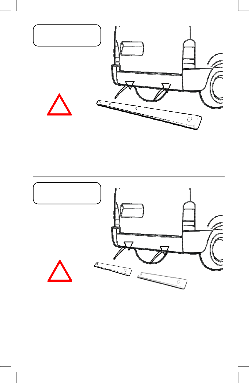
10
PROFILO PLASTICO
PLASTIC PROFILE
2 PROFILI PLASTICI
2 PLASTIC PROFILES
ATTENZIONE!
ATTENTION!
NOTE:
- L'ALTEZZA MINIMA DA TERRA DEVE ESSERE DI 50cm;
- DISTANZA TRA PROFILI: MIN 10cm, MAX 50cm
NOTE:
- THE MINIMUM DISTANCE FROM THE GROUND MUST BE 50cm;
- DISTANCE BETWEEN PROFILES: MIN 10cm, MAX 50cm
NOTE:
- L'ALTEZZA MINIMA DA TERRA DEVE ESSERE DI 50cm
NOTE:
- THE MINIMUM DISTANCE FROM THE GROUND MUST BE 50cm
ATTENZIONE!
ATTENTION!
!
!
ISEPSRF.p6511/05/2005, 17.1910
11
PROFILO PLASTICO
PLASTIC PROFILE
2 PROFILI PLASTICI
2 PLASTIC PROFILES
MONTAGGIO CON STAFFE
BRACKETS VERSION MOUNTING
USARE 3 STAFFE
USE 3 BRACKETS
USARE 4 STAFFE
USE 4 BRACKETS
ATTENZIONE!
ATTENTION!
!
NOTE:
- ANGOLO DI 90° TRA PARAURTI E PROFILO/I PLASTICO/I;
- L'ALTEZZA MINIMA DA TERRA DEVE ESSERE DI 50cm;
- DISTANZA TRA PROFILI PLASTICI: MIN 10cm, MAX 50cm
NOTE:
- BETWEEN BUMPER AND PLASTIC PROFILE/S THE ANGLE MUST BE 90°;
- THE MINIMUM DISTANCE FROM THE GROUND MUST BE 50cm;
- DISTANCE BETWEEN PROFILES: MIN 10cm, MAX 50cm
- ESEMPIO: SINGOLO PROFILO
- EXAMPLE: PLASTIC PROFILE
ISEPSRF.p6511/05/2005, 17.1911
12
- Inserire il connettore con
la fascetta BLU
- Connect the terminal
block with BLUE headband
- Inserire il connettore con
la fascetta ROSSA
- Connect the terminal block
with RED headband
R
1
2
- Inserire il connettore con la
fascetta NERA
- Connect the terminal block
with BLACK headband
4
CBS-4 RF
12/24V= CC
1
3
2
4
CONNESSIONI ELETTRICHE
ELECTRIC CONNECTIONS
+12V
R
Blue/black - Blu/Nero
Blue - Blu
Brown - Marrone
+24V
Yellow/black - Giallo/Nero
Yellow - Giallo
Z2
120
140
155
Z3
180 cm
180 cm
180 cm
Z1
60
80
100
34
ISEPSRF.p6511/05/2005, 17.1912
13
DATI TECNICI
Tensione di alimentazione.................................................................12/24V DC
Consumo corrente
(con motore acceso, retromarcia inserita, altoparlante attivo)..........100mA max
Temperatura di funzionamento..........................................................-25°C/+70°C
Frequenza dell’ultrasuono...............................................................................40kHz
TECHNICAL DATA
Power supply..........................................................................................12/24V DC
Current consumption
(with engine ON, reverse gear select and active buzzer)....................100mA max
Range of operational temperatures......................................................-25°C/+70°C
Frequency of the ultrasound.............................................................................40kHz
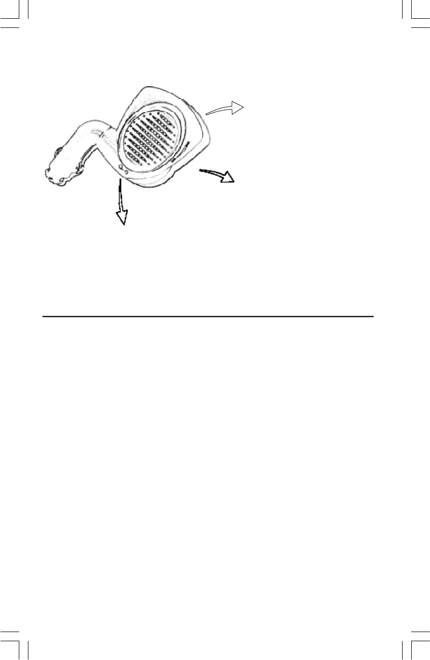
CARATTERISTICHE RICEVITORE
RECEIVER CHARACTERISTICS
- REGOLAZIONE VOLUME
- VOLUME SETTING
- LED COLORATI DI FUNZIONAMENTO
(ROSSO/VERDE e ARANCIONE)
- OPERATING COLOR LED
(RED/GREEN and ORANGE)
- PULSANTE PER
L'AUTOAPPRENDIMENTO E
LA REGOLAZIONE DEI
PARAMETRI
- BUTTON FOR SETTING AND
LEARNING PROCEDURE
ISEPSRF.p6511/05/2005, 17.1913

14
THE MANUFACTURER WILL NOT BE HELD RESPONSIBLE FOR DEFECT OR
MALFUNCTIONS OF THE PRODUCT OR CAR ELECTRICAL SYSTEM DUE TO
INCORRECT INSTALLATION OR HAVING GONE BEYOND THE LIMITS INDICATED
IN THE TECHNICAL DATA.
THE MANUFACTURER RESERVES THE RIGHT AT ANY TIME TO MAKE CHANGES
DEEMED NECESSARY WITHOUT PRIOR NOTICE.
NOTE
La ditta costruttrice declina ogni responsabilità per guasti o anomalie di funzionamento
del sistema o dell'impianto elettrico della vettura dovuti ad una cattiva installazione o
a un superamento delle caratteristiche indicate.
LA DITTA COSTRUTTRICE SI RISERVA IL DIRITTO DI EFFETTUARE VARIAZIONI IN
QUALSIASI MOMENTO SI RENDESSERO NECESSARIE SENZA L'OBBLIGO DI DARNE
COMUNICAZIONE.
NOTA
ISEPSRF.p6511/05/2005, 17.1914
15
1. “This device complies with Part 15 of the
FCC Rules. Operation is subject to the
following two conditions: (1) this device may
not cause harmful interference, and (2) this
device must accept any interference
received, including interference that may
cause undesired operation.”
2. “Changes or modifications not expressly
approved by the party responsible for
compliance could void the user’s authority
to operate the equipment.”
!
ISEPSRF.p6511/05/2005, 17.1915

16
Factory Management & Marketing
Via Don Locatelli, 51
20040 RONCELLO - (MI) Italy
Tel. +39 039 682561 - Fax. +39 039 68256248
cod.: ISEPSRF
FILENAME: ISEPSRF.P65
ISEPSRF.p6511/05/2005, 17.1916