Lattice Semiconductor 5397X Video Card User Manual SiI DS 0044 A
Silicon Image, Inc. Video Card SiI DS 0044 A
Users Manual

®
Technology
Orion and Maia ADD2 Card
User’s Guide
Document # SiI-UG-0044-A
FCC NOTICE
INFORMATION FOR THE USER
Silicon Image, Inc.
FCC ID: SAX5397X
This device complies with Part 15 of the FCC Rules. Operation is subject to the
following two conditions: (1) This device may not cause harmful interference, and
(2) This device must accept any interference received, including interference that
may cause undesired operation. This Product Certified to meet the Standards in
the categories listed below:
Information Technology Equipment
EMI: FCC Part 15 Class B; ICAN ICES-003 Class B; EN55022 Class B
This Class B digital apparatus complies with Canadian ICES-003. Cet appareil
numérique de la classe B est conforme à la norme NMB-003 du Canada.
This equipment has been tested and found to comply with the limits for a Class B digital device,
pursuant to Part 15 of the FCC Rules. These limits are designed to provide reasonable
protection against harmful interference in a residential installation. This equipment generates,
uses and can radiate radio frequency energy and, if not installed and used in accordance with
the instructions, may cause harmful interference to radio communications. However, there is no
guarantee that interference will not occur in a particular installation. If this equipment does
cause harmful interference to radio or television reception, which can be determined by turning
the equipment off and on, the user is encouraged to try to correct the interference by one or
more of the following measures:
1) Reorient or relocate the receiving antenna.
2) Increase the separation between the equipment and receiver.
3) Connect the equipment into an outlet on a circuit different from that to
which the receiver is connected.
4) Consult the dealer or an experienced radio/TV technician for help.
The user may find the following publication prepared by the Federal Communications
Commission helpful:
"How to Identify and Resolve Radio-TV Interference Problems" (Stock
Number 004-000-00345-4).
Available exclusively from the Superintendent of Documents, Government Printing Office,
Washington, DC 20402 (telephone 202-512-1800).
FCC WARNING
Changes or modifications not expressly approved by the party responsible for
compliance to Part 15 of the FCC Rules could void the user's authority to operate
the equipment.
Orion and Maia ADD2 Card User Guide
Silicon Image, Inc.
SiI-UG-0044-A
May 2004
Application Information
To obtain the most updated Application Notes and other useful information for your design, please visit the Silicon
Image web site at www.siliconimage.com or contact your local Silicon Image sales office.
Copyright Notice
This manual is copyrighted by Silicon Image, Inc. Do not reproduce, transform to any other format, or
send/transmit any part of this documentation without the expressed written permission of Silicon Image, Inc.
Trademark Acknowledgment
Silicon Image, the Silicon Image logo, PanelLink® and the PanelLink® Digital logo are registered trademarks of
Silicon Image, Inc. TMDSTM is a trademark of Silicon Image, Inc. VESA® is a trademark of the Video Electronics
Standards Association.
Disclaimer
This document provides technical information for the user. Silicon Image, Inc. reserves the right to modify the
information in this document as necessary. The customer should make sure that they have the most recent data
sheet version. Silicon Image, Inc. holds no responsibility for any errors that may appear in this document.
Customers should take appropriate action to ensure their use of the products does not infringe upon any patents.
Silicon Image, Inc. respects valid patent rights of third parties and does not infringe upon or assist others to
infringe upon such rights.
All information contained herein is subject to change without notice.
Revision History
Revision Date Comment
SiI-UG-0044-A 5/24/04 User’s Guide – 1st Release.
© 2004 Silicon Image Inc.
SiI-UG-0044-A ii

Orion and Maia ADD2 Card User Guide
iii SiI-UG-0044-A
TABLE OF CONTENTS
Introduction..................................................................................................................................................... 1
Video Resolutions Supported ..................................................................................................................... 3
Board Description........................................................................................................................................... 4
PCI-Express Connector:.......................................................................................................................... 4
Configuration EEPROM .......................................................................................................................... 4
SiI 1364 Tx and I2C Circuits.................................................................................................................... 4
Hot Plug and Receiver Sense ................................................................................................................. 5
Physical Dimensions and Devices.............................................................................................................. 5
Usage ............................................................................................................................................................. 7
Enabling DVI Display and Changing Resolutions....................................................................................... 7
Layout Requirements ................................................................................................................................... 10
LIST OF FIGURES
Figure 1. Orion ADD2-N Card - Blue.............................................................................................................. 1
Figure 2. Maia ADD2-R Card - Red................................................................................................................ 1
Figure 3. Functional Blocks of ADD2 Card..................................................................................................... 4
Figure 4. Physical Dimension and Device list ................................................................................................ 5
Figure 5. Enabling Digital Display via Mouse................................................................................................. 7
Figure 6. Enabling Digital Display via Keyboard ............................................................................................ 8
Figure 7. Changing Resolution....................................................................................................................... 9
Figure 8. SDVO and TMDS Trace Guideline................................................................................................ 10
LIST OF TABLES
Table 1. Video Resolutions Supported ........................................................................................................... 3
Table 2. Device Description............................................................................................................................ 6
Orion and Maia ADD2 Card May 2004
User’s Guide
Introduction
This purpose of this document is to introduce the ADD2 (Advanced Digital Display, 2nd Generation) Card, its
features and its usage. The ADD2 Card has been designed to work in Intel Motherboards that have PCI-Express
slots and support SDVO (Serial Digital Video Output) technology. It will not work on motherboards or systems that
support earlier DVO-based ADD (AGP Digital Display) Cards.
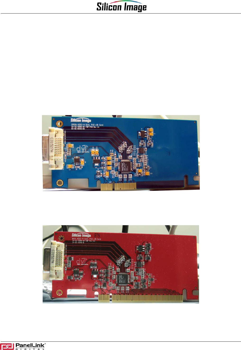
SDVO-based systems have 2 different layout options: non lane-reversed and lane-reversed, which require
separate ADD2 Card layout. The Orion ADD2-N (non lane-reversed) and Maia ADD2-R (lane reversed) cards
were designed for this requirement. They can be easily distinguished from their color code: ADD2-N is color
coded BLUE (see Figure 1) and ADD2-R is color coded RED (see Figure 2). Both cards have been designed to
meet the DVI (Digital Visual Interface) 1.0 standard.
Figure 1. Orion ADD2-N Card - Blue
Figure 2. Maia ADD2-R Card - Red
1 SiI-UG-0044-A

Orion and Maia ADD2 Card User Guide
SiI-UG-0044-A 2
The Orion ADD2-N and Maia ADD2-R cards share common features such as:
• Dual Pad: Supports either the 64-pin SiI1364 package or 48-pin SiI1362 package (see note below)
• Low Profile Card dimensions
• Retention mechanism for excellent board stability
• Four-layer PCB for good thermal and signal integrity.
• DVI Single Link with 100ohm differential impedance
• EMI shielding on Layer 1 and Layer 4 via copper pour
• Identical Bill of Materials and layout, with exception of ADD2+ enable pull up on ADD2-R and SDVO input
• 2KB serial EEPROM to store configuration information
• No special drivers required to enable card in an SDVO based system.
The Orion ADD2-N and Maia ADD2-R cards are available from Silicon Image as part of a Starter Kit. The Starter
Kit includes all necessary items including high profile and low profile brackets for sampling and documents for
mass production.
Available documents in Starter Kits SiI-SK-0025 for ADD2-N and SiI-SK-0026 or by request:
1. Layout in PowerPCB 5.0 format
2. Gerbers for both Orion ADD2-N and Maia ADD2-R with X-Y data for assembly
3. Bill of Materials with alternate vendor sources for discrete devices
4. Low Profile and High Profile bracket dimensions, along with vendor information.
Note on SiI1362 pads: The ADD2 cards provide 48-pin support for specialized applications only, since the
SiI1362 package does not support the configuration EEPROM interface. The host system BIOS would require
special enhancements by the OEM to support this configuration. Silicon Image does not provide any software
support for use of the SiI1362 package on an ADD2 card.
Orion and Maia ADD2 User Guide
3 SiI-UG-0044-A
Video Resolutions Supported
The ADD2 card will support all video modes that can be sent over a single link DVI connection, with pixel rates
ranging from 25 MHz to 162 MHz. This includes, but is not limited to, the following VESA and industry standard
modes. Note that some resolution selections may be disabled by the Grantsdale G drivers.
Table 1. Video Resolutions Supported
Resolution Vertical Refresh Rate Horizontal Frequency Pixel Frequency
640 x 350 85 Hz 37.9 kHz 31.5 MHz
640 x 400 85 Hz 37.9 kHz 31.500 MHz
720 x 400 85 Hz 37.9 kHz 35.500 MHz
640 x 480 60 Hz 31.5 kHz 25.175 MHz
640 x 480 72 Hz 37.9 kHz 31.500 MHz
640 x 480 75 Hz 37.5 kHz 31.500 MHz
640 x 480 85 Hz 43.3 kHz 36.000 MHz
800 x 600 56 Hz 35.1 kHz 36.000 MHz
800 x 600 60 Hz 37.9 kHz 40.000 MHz
800 x 600 72 Hz 48.1 kHz 50.000 MHz
800 x 600 75 Hz 46.9 kHz 49.500 MHz
800 x 600 85 Hz 53.7 kHz 56.250 MHz
1024 x 768 60 Hz 48.4 kHz 65.000 MHz
1024 x 768 70 Hz 56.5 kHz 75.000 MHz
1024 x 768 75 Hz 60.0 kHz 78.750 MHz
1024 x 768 85 Hz 68.7 kHz 94.500 MHz
1152 x 864 75 Hz 67.5 kHz 108.000 MHz
1280 x 960 60 Hz 60.0 kHz 108.000 MHz
1280 x 960 85 Hz 85.9 kHz 148.500 MHz
1280 x 1024 60 Hz 64.0 kHz 108.000 MHz
1280 x 1024 75 Hz 80.0 kHz 135.000 MHz
1280 x 1024 85 Hz 91.1 kHz 157.500 MHz
1600 x 1200 60 Hz 75.0 kHz 162.000 MHz
Orion and Maia ADD2 Card User Guide
SiI-UG-0044-A 4
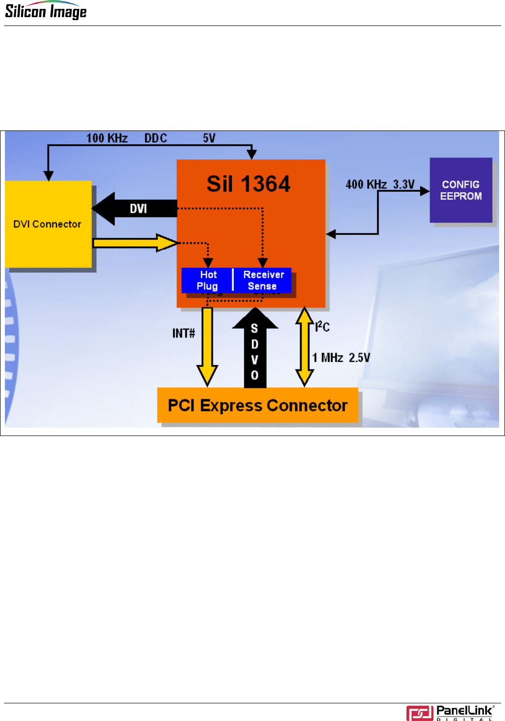
Board Description
The basic block diagram of the Orion and Maia ADD2 cards is illustrated in Figure 3. Each block is briefly
explained below.
Figure 3. Functional Blocks of ADD2 Card
PCI-Express Connector:
The PCI-Express slot passes all SDVO signals including the 1MHz-speed 2.5V I2C bus from the Grantsdale G
chipset and SDVO signals, and returns INT# (Serial Interrupt) from the SiI 1364 Tx. Both ADD2-N and ADD2-R
have x16 length PCI-Express card-edge connectors.
Configuration EEPROM
The Configuration EEPROM stores vital configuration header information for the Grantsdale G driver to recognize
and configure the SiI 1364 Tx as an SDVO-based DVI device. The EEPROM I2C bus from the SiI 1364 Tx
operates at 400kHz at 3.3V. The SiI 1364 Tx has internal 3.3V pull-up resistors for this bus; therefore, no external
pull-up resistors are stuffed. All ADD2 cards are shipped with a pre-programmed EEPROM installed. Refer to the
Bill of Materials for additional EEPROM information.
SiI 1364 Tx and I2C Circuits
The SiI 1364 Tx is the device that links the Grantsdale G platform to a DVI flat panel display. Grantsdale G reads
the EDID of a connected display, or retrieves configuration information from the EEPROM, by way of the I2C
pass-through of the SiI 1364 Tx. This pass-through interface operates at a 100kHz rate and provides the
required level shifting from the 2.5V Grantsdale G interface to either the 3.3V EEPROM interface or the 5V DDC
interface. The SiI 1364 Tx also provides an interrupt signal to the Grantsdale G to signal a display attach/detach
event using the DVI Hot Plug function.
Orion and Maia ADD2 User Guide
5 SiI-UG-0044-A
Note that the 2.5V I2C interface to the Grantsdale G chipset operates at speeds up to 1MHz when communicating
with the on-chip registers.
Hot Plug and Receiver Sense
Either Hot Plug or Receiver Sense can indicate attachment of a Digital Display to the ADD2 Card.
Hot Plug detects whether a display is attached by sensing when the display returns a 2V to 5V level on
the DVI connector Hot Plug pin.
Receiver Sense detects whether an attached display has applied power to its TMDS receiver by sensing
the voltage on the TMDS lines.
With this technology, no external circuit is required. While the ADD2 card supports both functions, only one can be
enabled at a time. At power-up time the Receiver Sense circuit is enabled, but the motherboard drivers typically
program the chip so that the Hot Plug function is used instead.
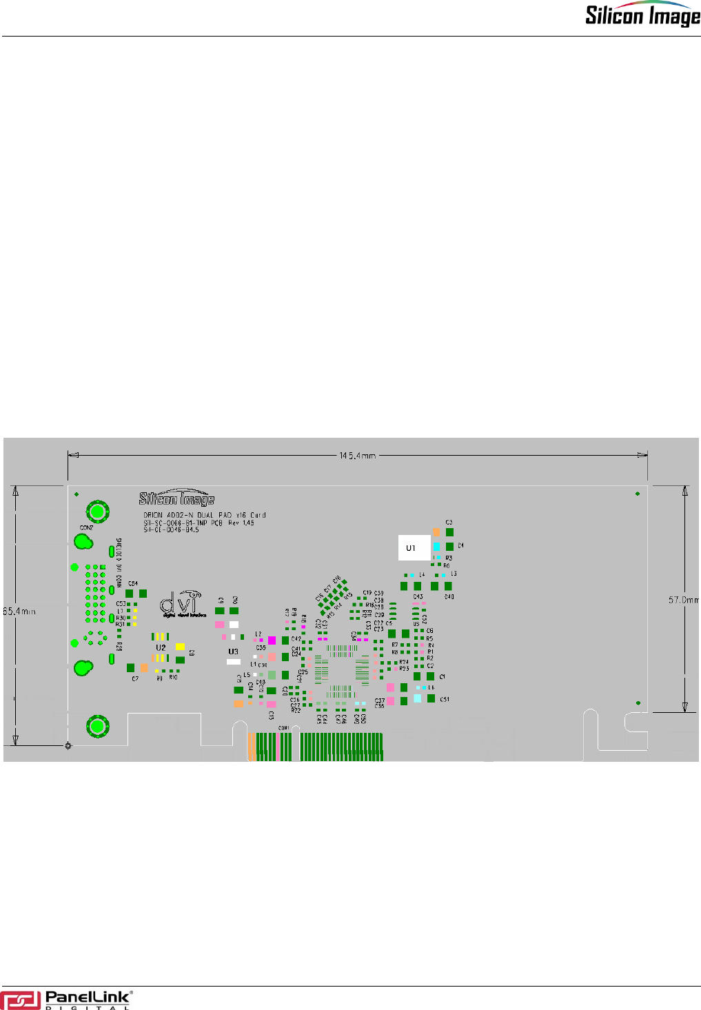
Physical Dimensions and Devices
Figure 4 illustrates the physical dimensions of the ADD2-N and ADD2-R cards. The PCI Express Card
Electromechanical Specification requires the maximum height of a low profile card to be 2.731inches(69.37mm)
or lower. The Orion ADD2-N and Maia ADD2-R cards are designed to meet this specification at a height of
2.57inch (65.4mm).
Figure 4. Physical Dimension and Device list
Orion and Maia ADD2 Card User Guide
SiI-UG-0044-A 6
Table 2 describes the basic purpose of the devices shown in Figure 4. Both ADD2-N and ADD2-R have the same
placement for the devices, with only minor changes to the reference designators.
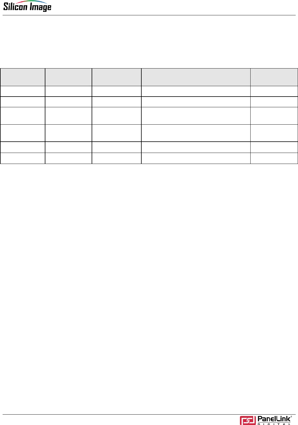
Table 2. Device Description
ADD2-N Ref
Designator ADD2-R Ref
Designator Device Purpose Package Type
U1 U1 LM317EMP 12V to 3.3V regulation for PVCC SOT 223
U2 U2 LM317L 12V to 5V for DDC I2C and Hot Plug SOIC 8
U3 U3 LM1117-1.8V
3.3V to 1.8V regulation for
VCC and SVCC. SOT 223
U4 U5 24LC02 2KB EEPROM to store
configuration information. SOIC 8
U5 U4
SiI 1364 Tx DVI Transmitter (default) 64-pin TQFP
U7 U7
SiI 1362 Tx DVI Transmitter (not used) 48-pin LQFP
Orion and Maia ADD2 User Guide
7 SiI-UG-0044-A
Usage
Insert the card in the PCI-Express slot of the Grantsdale G system, attach a DVI flat panel display using a DVI
cable, and boot the system. Use the correct ADD2 card (-N or -R) for the intended system. Using the wrong card
will not cause any damage, but it will not be initialized or show a display. The system should have Grantsdale G
drivers installed.
Enabling DVI Display and Changing Resolutions
All Grantsdale G video drivers provided by Intel have built in support to enable the ADD2 cards. No specialty
drivers are required. It is important to note that Silicon Image does not release, generate, or provide drivers. All
necessary drivers are available from Intel Corporation.
Download the latest Grantsdale G drivers from the Intel website or https:\\platformsw.intel.com. Install the driver
using the setup.exe file. Once installed, reboot the system and follow the instructions below
The following section provides guidance in using this application to capture and generate a DVI compliance
report.
a. Attach a DVI flat panel display to the ADD2 card. Ensure that the display is turned on.
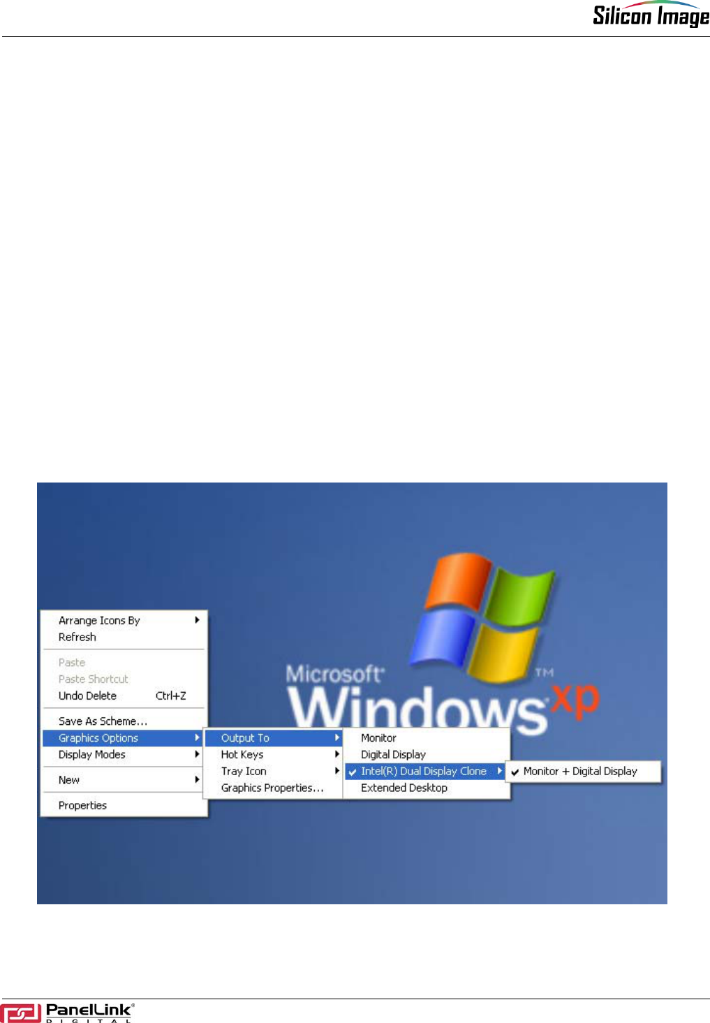
b. On the Windows Desktop, right click and a dialog box will appear. Select “Graphics Options” and, if a digital
flat panel is attached to the system, the “Output To” selection will be available. Select either the “Digital Display”
option or the “Intel® Dual Display Clone” option to enable the digital flat panel.
Figure 5. Enabling Digital Display via Mouse
Orion and Maia ADD2 Card User Guide
SiI-UG-0044-A 8
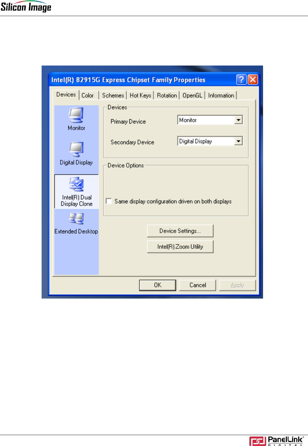
c. To see the dialog box shown in Figure 6, simultaneously press “SHIFT+CTRL+F12” and release. On the left
column, icons list the available options for display. Select either Digital Display for single display only or Intel®
Dual Display Clone for simultaneous Analog and Digital Display.
Figure 6. Enabling Digital Display via Keyboard
Orion and Maia ADD2 User Guide
9 SiI-UG-0044-A
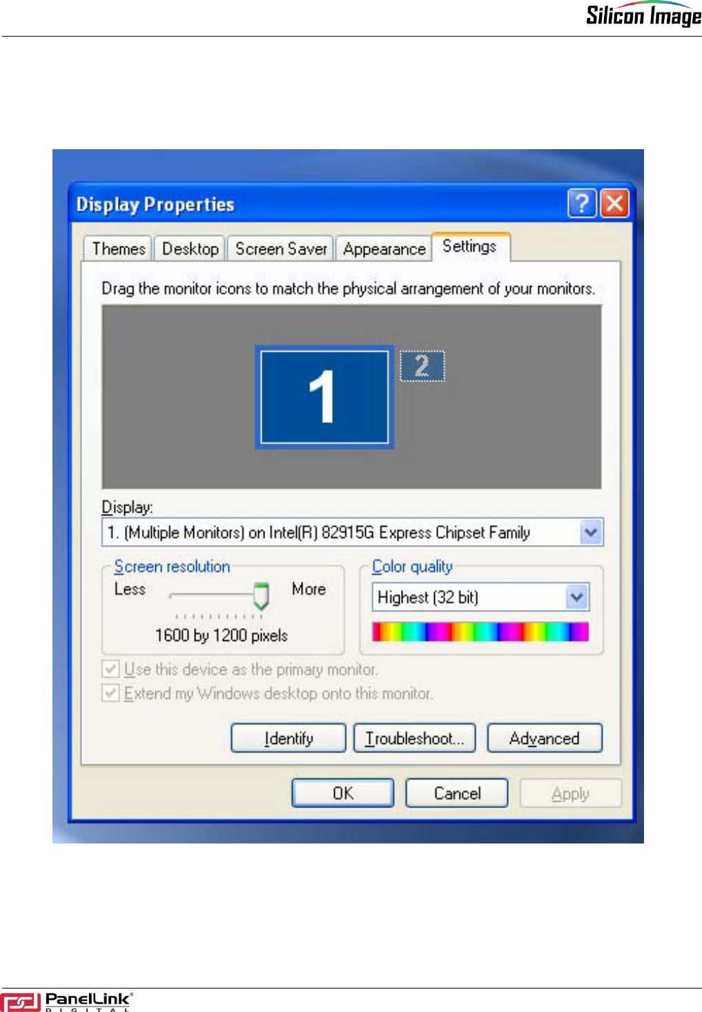
d. To change resolution, right click on the mouse and select Properties. Select the “Settings” tab as shown in
Figure 7. The slider in the Screen Resolution box allows change of resolution. Slide the marker on the slider bar
to the intended resolution and click OK.
Figure 7. Changing Resolution
Orion and Maia ADD2 Card User Guide
SiI-UG-0044-A 10
Layout Requirements
It is highly recommended that the provided layout and Gerber files be used for production of the ADD2 cards.
The cards are certified for acceptable radiated emissions levels as long as they are built as directed. Changes to
the silkscreen are allowed, but changes to layout, stack-up, or component selection will require the design to be
re-certified.
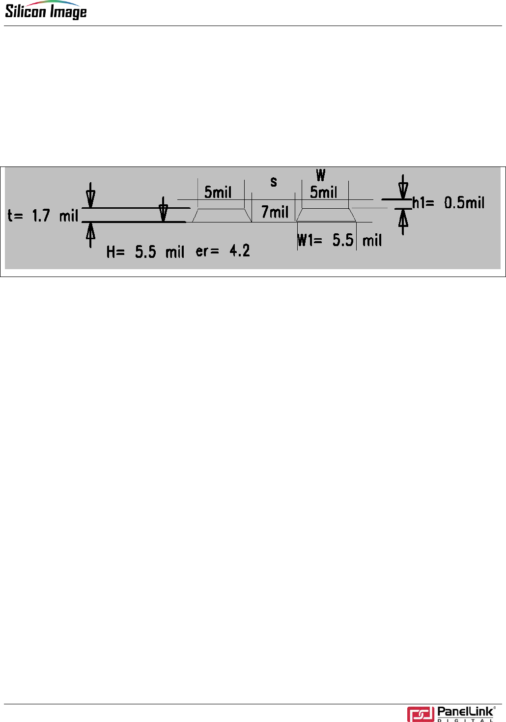
Both Orion ADD2-N and Maia ADD2-R cards follow the same trace guidelines for high-speed signals. The high-
speed traces consist of the SDVO input and the TMDS output of the SiI 1364 Tx. Figure 8 shows the appropriate
dimensions used to achieve a 100-ohm differential impedance between the traces.
Figure 8. SDVO and TMDS Trace Guideline
As shown in Figure 8, the trace width should be kept at 5 to 5.5 mils at layer 1, and the gap at 7 mil between each
pair. In addition, the stack-up between layer 1 and layer 2 should be kept at 5.5 mil. For detailed instructions on
all board fabrication related questions, please refer to the appropriate Gerber file for the Orion ADD2-N card or
the Maia ADD2-R card.

Orion and Maia ADD2 User Guide
11 SiI-UG-0044-A
© 2004 Silicon Image. Inc. SiI-UG-0044-A
Silicon Image, Inc. Tel: (408) 616-4000
1060 E. Arques Avenue Fax: (408) 830-9530
Sunnyvale, CA 94085 E-mail: salessupport@SiImage.com
USA Web: www.siliconimage.com