Lattice Semiconductor MOD621X MOD6213/MOD6212 transiver User Manual Module Guide
Lattice Semiconductor Corporation MOD6213/MOD6212 transiver Module Guide
Users Manual

SiBEAM Snap™
OEM Module Installation Guide for
MOD6212/13
Module Installation Guide
2 ©2017 SiBEAM, Inc., a Lattice Semiconductor company.
All rights reserved. CONFIDENTIAL
Introduction
The Lattice Semiconductor MOD6212/13 Wireless module provides a data interface
compatible with USB device, which allows reception/transmission of various data rate
from/to any USB compliant device. OEM can develop a system equipped with this module to
wirelessly connect their high data sources to the target device.
The MOD6212/13 modules fit into a variety of industrial designs. No software needs to
initialize and to control the module to achieve the wired connectivity offered. The
MOD6212/13 module is a completely self-contained autonomous wireless sub-system that
connects to a system board that provides the wired connectivity from a single port to a full
featured multiport, multi-standard system. The advantage of this design is that the
complexity of the wireless system, radio performance, regulatory requirements, and
compliance to standards are all eliminated. This system interface carries data, power, and
control signals. The module is pre-certified and is fully tested for fast time-to-market.
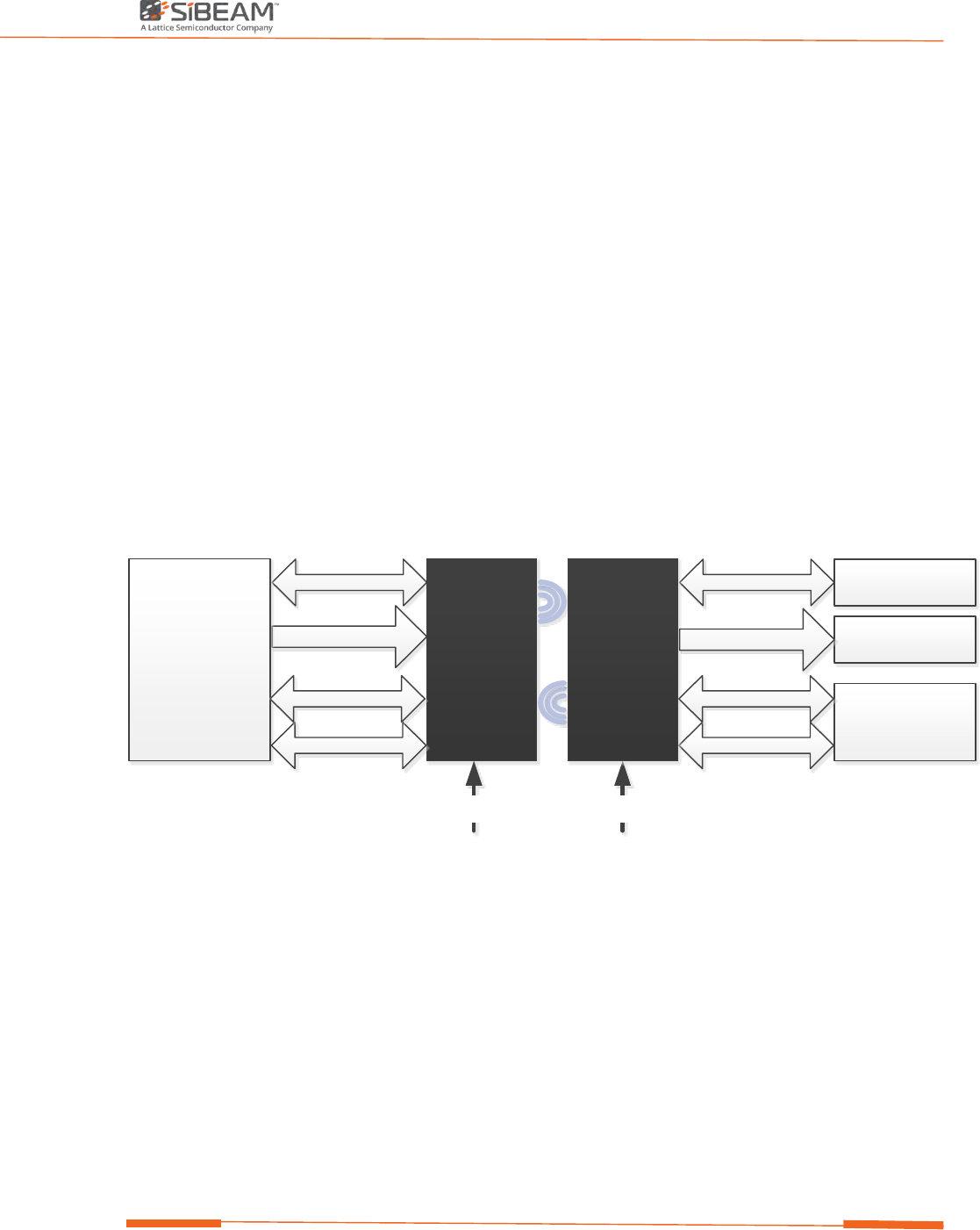
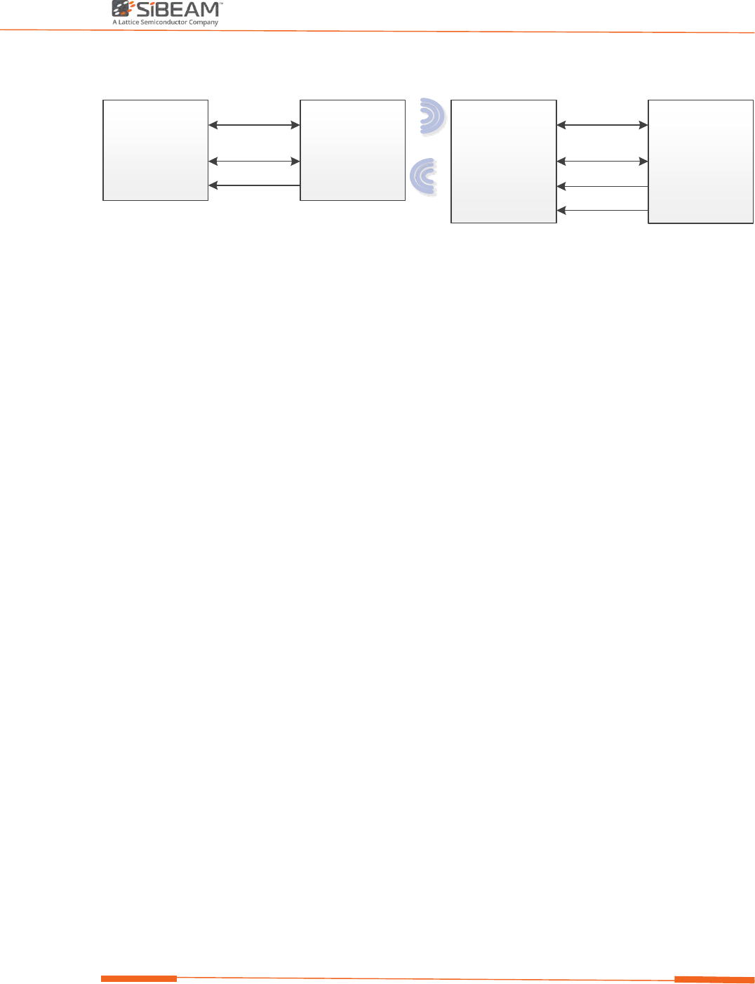
MOD6212/13 Diagram
USB3.0/2.0
I2C Tunnel
System
Host MOD6212
USB3.0/2.0
I/O RST
USB devices
I2C peripherals
System controller
3.3V 3.3V
MOD6213
I2C D eb ug
I/O RST
I2C D eb ug
I2C Tunnel
Figure 1. MOD6212/13 Transceiver Module Wireless connector principle
MOD6212/13 transceiver Features
• USB 3.0 and 2.0 connections: SS, HS, FS, LS.
• Up to 6Gbps full duplex data-rate
• I2C tunneling for remote I2C connections
• Fully automatic device detection and connection
• Close proximity operation
• Single chip IC, direct connector replacement
• Integrated antenna
• No software driver required
Module Installation Guide
3 ©2017 SiBEAM, Inc., a Lattice Semiconductor company.
All rights reserved. CONFIDENTIAL
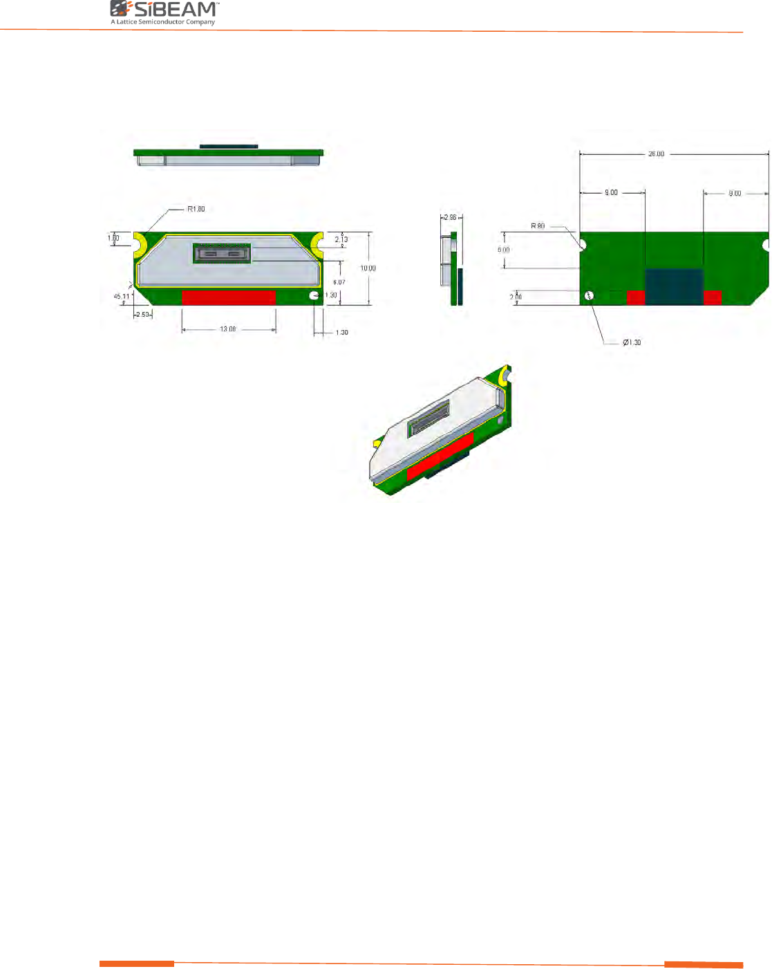
MOD6212/13 Transceiver Module Dimensions
Figure 2. MOD6212/13 Transceiver Module Dimension (in mm)

Module Installation Guide
4 ©2017 SiBEAM, Inc., a Lattice Semiconductor company.
All rights reserved. CONFIDENTIAL
MOD6212/13 Transceiver Module Pinout
Table 1. Signal pinout
Pin Name Type Dir Group Description
1 3V3 Power Input Power 3.3V +/-5% power supply
2 SCL Digital In/Out
O.D.
I2C I2C Clock, Tunneling port. SB6210/SB6212 Connect to
Master; SB6211/SB6213 Connect to Slave
3 3V3 Power Input Power 3.3V +/-5% power supply
4
SDA
Digital
In/Out
O.D.
I
2
C
I
2
C Data, Tunneling port. SB6210/SB6212 Connect to Master;
SB6211/SB6213 Connect to Slave
5 3V3 Power Input Power 3.3V +/-5% power supply
6 SCL_DBG I2C Bi-Dir USB I2C Data, Debug port. Connection to debug controller not
required for normal operation.
7 GND Power Power Ground
8 SDA_DBG I2C In/Out
O.D.
Debug I2C Data, Debug port. Connection to debug controller not
required for normal operation.
9 GND Power Power Ground
10 GPI Digital Input GPIO General purpose input. Status of this input is reflected on
the GPO pin on the opposite side of an active wireless link.
11 WAKE_UP Digital Input Control Force the link to W0 State. This is useful to bypass USB states,
when I2C tunnel or GPI signal needs to be used, while the link
is in low power states. Active High. Optional.
12
VBUS_SENSE
Digital
Input
USB
USB VBUS status input , 3V3
13 ATB_N Analog Output Debug Differential analog test bus - negative terminal
14
GND
Power
Power
Ground
15 ATB_P Analog Output Debug Differential analog test bus - positive terminal
16
SSRX-
Analog
Input
USB
USB Super speed Neg Input
17 RST Digital Input Config Reset Input, active HIGH
18
SSRX+
Analog
Input
USB
USB Super speed Pos Input
19 ID_IN Digital Input USB USB ID Input
20 GND Power Power Ground
21 ID_VAL Digital Input USB USB ID Valid Input
22 SSTX+ Analog Output USB USB Super speed Pos Output
23 ID_OUT Digital Output USB USB ID Output
24 SSTX- Analog Output USB USB Super speed Neg Output
25 VBUS_EN Digital Output USB USB VBUS status output, 3V3
26 GND Power Power Ground
27
LEDO
Digital
Output
Config
LED output
28 D+ Analog Bi-Dir USB USB High Speed/Full Speed/Low Speed Pos I/O
29
GPO/INT
Digital
Output
GPIO
General purpose output. When a wireless link is active, the
status of this output reflects the GPI pin on the opposite side
of the wireless link. Also used as I2C tunnel interupt
30 D- Analog Bi-Dir USB USB High Speed/Full Speed/Low Speed Neg I/O
Module Installation Guide
5 ©2017 SiBEAM, Inc., a Lattice Semiconductor company.
All rights reserved. CONFIDENTIAL
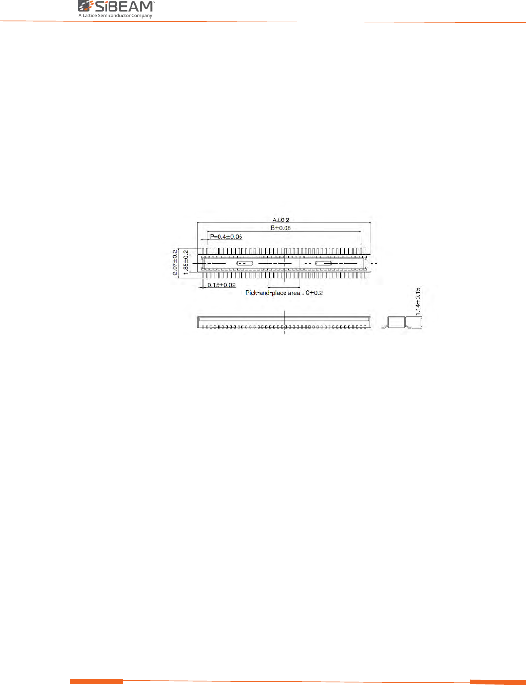
MOD6212/13 Transceiver Module Connector
The module is designed to be connected to the system board through a single board to board
connector:
On the module side:
The connector type is DF40 from Hirose
Part number: DF40C-30DP-0.4V (51)
Description: Dual row Board to Board Receptacle (Plug), 0.4 pitch, 50 pins
A=7.52mm, B=5.6mm, C =1.5mm
Figure 3. Module side connector.

Module Installation Guide
6 ©2017 SiBEAM, Inc., a Lattice Semiconductor company.
All rights reserved. CONFIDENTIAL
MOD6212/13 Transceiver Module Functional description
USB 3.0 Interface
The MOD6212/13 Transceiver Module interfaces directly with a USB 3.0 port without
requiring any additional control or interface logic. “ID_IN” and “ID_VAL” strapping pins
on the Transceiver Module are used along with wireless communication to establish the
USB port personality as either upstream facing or downstream facing. The ID_OUT signal
from each transceiver to the attached USB port indicates upstream or downstream
facing transceiver operation.
Table 2. Transceiver Personality Based on Pair Configuration
Pair Configuration
Transceiver Personality
Application Example
MOD6212 MOD6213 MOD6212 MOD6213 MOD6212 MOD6213 MOD6212 MOD6213
ID_IN ID_VAL ID_IN ID_VAL ID_OUT ID_OUT Facing Facing VBUS_En VBUS_En
1 1 0 1 0 Z US DS 0 1 2 in 1 Laptop
0
1
1
1
Z
0
DS
US
1
0
Sport Camera/ Storage
X 0 1 1 Z 0 DS US 1 0 Mobile Phone (as Device)
X 0 0 1 0 Z US DS 0 1 Mobile Phone (as Host)
The “VBUS” supply from the upstream USB port is used as a VBUS_SENSE input to the
transceiver. Note that a resistor divider or equivalent circuit should be used to reduce the
+5V VBUS voltage level to a +3.3V voltage level that is compatible with the VBUS_SENSE
input. The VBUS status is sent to the downstream facing transceiver, where the
“VBUS_EN” signal is used to control the local VBUS status at the downstream USB
connection.
When MOD6212 based Module transceiver is located in close proximity to another
MOD6213 based Module transceiver, the two transceivers automatically establish a
wireless connection, enabling high speed communication with the devices on the other
side of the link. Establishing a wireless link is analogous to plugging in a USB cable. Once
“connected”, this link will act and behave just like a wired USB 3.0 interface. The
“ID_OUT” signal emulates the proper grounding of the ID pin that would be seen when
attaching a USB 3.0 cable between devices. The “VBUS_EN” signal can be used to either
drive a VBUS logic input, or an external FET transistor to actually switch the VBUS power
to the downstream facing USB interface.
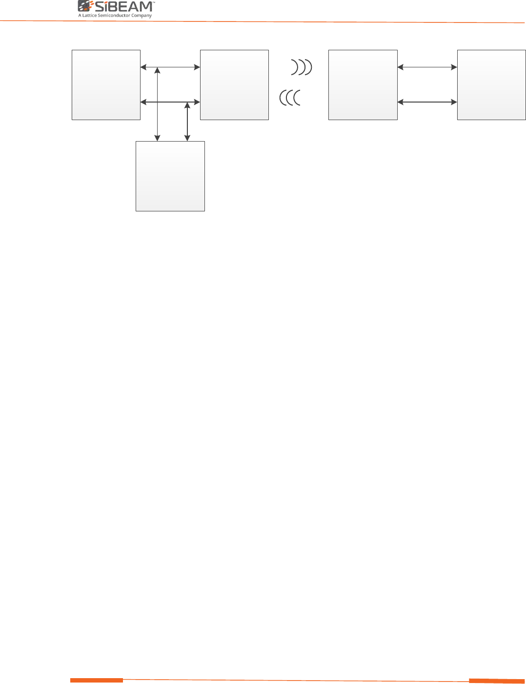
I2C Tunneling
I2C tunneling is a key feature of the MOD6212/13 Transceiver Module. It simply allows
an I2C master on the MOD6212 to communicate with I2C devices connected to the
MOD6213.
Module Installation Guide
7 ©2017 SiBEAM, Inc., a Lattice Semiconductor company.
All rights reserved. CONFIDENTIAL
I2C Master SK6210/12-MOD SK6211/13-MOD I2C Slave(s)
SDA
SCL
SDA
SCL
I2C Slave(s)
SDA
SCL
SDA
SCL
SCL
SDA
Figure 5. MOD6212/13 Transceiver Module I2C tunnel principle
GPI, GPO, and LEDO
The MOD6212/13 Transceiver Module contains a general purpose input (GPI) and a general
purpose output (GPO) as well as a dedicated led output (LEDO) pin. At system level those can
be routed to a Host MCU or directly to LED devices.
The LEDO indicates the state of the wireless link. A persistent low (off state) indicates that
the module transceiver is powered down or being held in reset. A periodic high (blink)
indicates that the device is scanning for a connection. A high (on state) indicates that RF link
is established.
Without a link present, GPO will be low (off state). When a link is established, and the
transfer is in the Full speed mode (W0 state), the GPO will reflect the state of the GPI pin on
the opposite side of the link. If the GPI pin on the opposite side of the link keeps high, the
GPO output can be used to indicate a high speed data transfer. If the device goes into a
“Detached State”, (link established but no data being transferred) the GPO signal will
periodically go high (blink).
Each GPI pin can be used to control the state of the GPO pin on the opposite side of the link,
but only when the link is in a Full Speed mode (W0 state).
GPI on MOD6212 to GPO on MOD6213 can also be used as interrupt function along with the
WAKE_UP pin to wake up the wireless link and I2C host for service. Asserting WAKE_UP will
force the wireless link to W0 state or stop the link from entering low power modes (W2, W3,
IDLE). This combination of WAKE_UP pin and GPO/INT works together with the I2C Tunnel
function to prevent the need for polling on the I2C tunnel from the master side.
Module Installation Guide
8 ©2017 SiBEAM, Inc., a Lattice Semiconductor company.
All rights reserved. CONFIDENTIAL
I2C Mas ter MOD6212 MOD62 13 I2C Sla ve(s)
SDA
SCL
SDA
SCL
SDA
SCL
SDA
SCL
INT GPO INT
GPI
WA KE_UP
Figure 6. MOD6212/13 Transceiver Module interrupt based I2C tunnel
Reset
The MOD6212/13 Transceiver module has an RST input pin that keeps the device in standby.
The reset circuit is designed such that if an RST signal is not available. The part will generate
an internal RST signal as the device is powered on.
No device driver needed
MOD6212/13 Transceiver module is software free product. Module does not need to install
and to initialize the device driver to control the module to achieve the wired connectivity
offered. As soon as the MOD6212/13 module detects each other through proximity
detection and establishes the RF link within second, user could start the USB data transfer
now.

Module Installation Guide
9 ©2017 SiBEAM, Inc., a Lattice Semiconductor company.
All rights reserved. CONFIDENTIAL
Modular approval for Lattice MOD6212/13 transmitter
MOD6212/MOD6213 radio is a low power 60GHz full duplex radio operating under §15.255 that
provides very short range (<15mm) contactless bidirectional USB data transfer between two hosts.
Spatial separation between receive and transmit antennas is used to allow simultaneous operation of
two radio links on the same frequency to provide bidirectional data transfer.
Lattice is a module supplier and does not manufacture host systems.
Modular transmitter should meet all the applicable requirements.
1. The final host system shall be subject to unwanted radiated emission testing up to 40GHz with
transmitter active and a test report shall be provided to the grantee. The grantee shall review that
report and acknowledge to the host manufacturer that it demonstrates compliance.
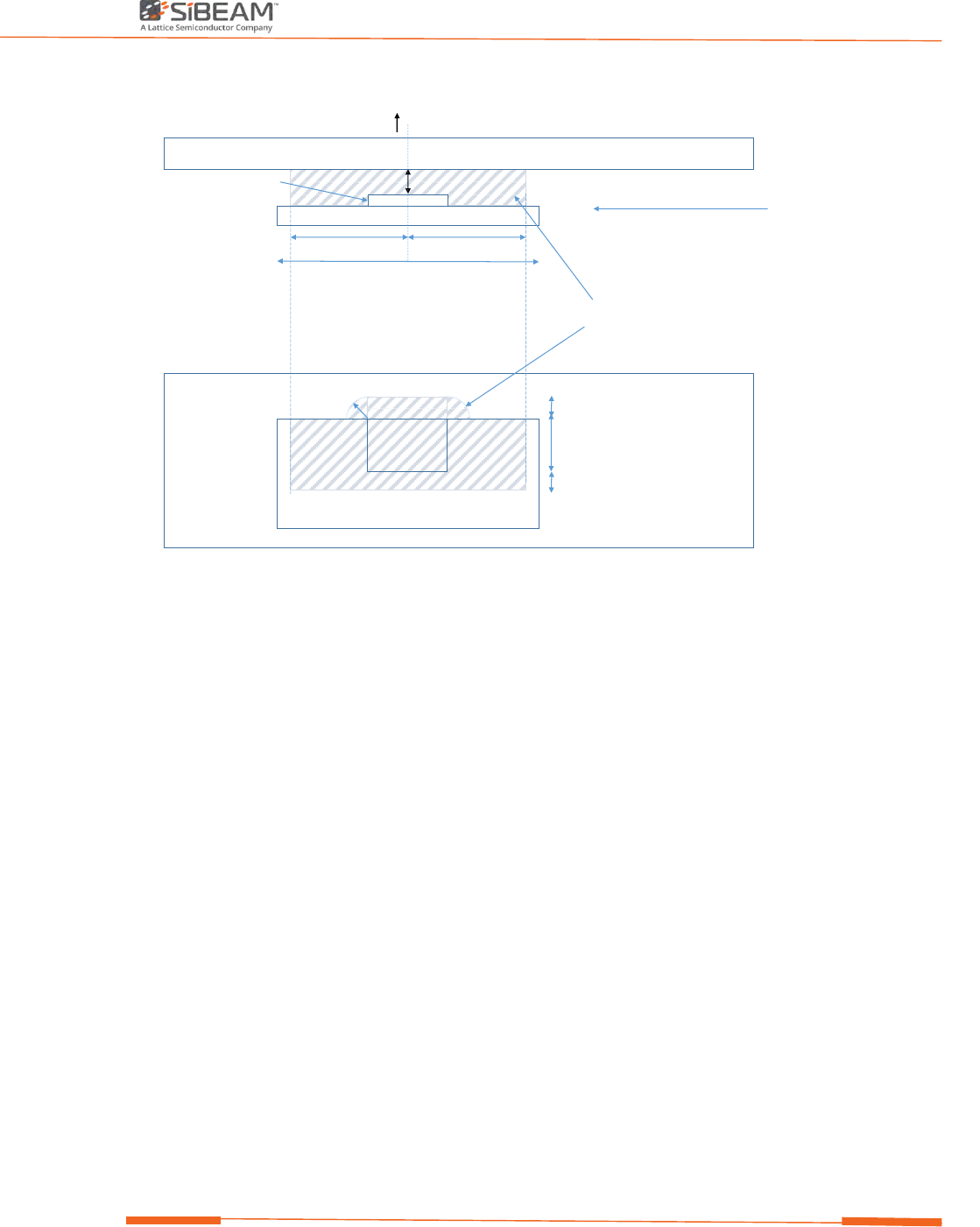
2. Host manufacturer module placement shall comply with the following requirements:
a) The shielded side of the module shall face inwards to the host;
b) The open side of the module shall be immediately adjacent to the enclosure with no intermediate
conducting material;
c) The spacing between unshielded side of module and enclosure shall be 3mm or less and must be free
of any conducting material within a defined exclusion region (Figure 7).
d) The enclosure shall be constructed from non-conducting material adjacent to that exclusion region.
Module Installation Guide
10 ©2017 SiBEAM, Inc., a Lattice Semiconductor company.
All rights reserved. CONFIDENTIAL
A
Module PCB
Host enclosure
(insulating)
Dimension A <= 3mm
26mm
10mm 10mm
Region with no metal permitted
Inward facing shielded side
MFC-VFBGA package
FRONT ELEVATION
PLAN ELEVATION
2.5mm
2.5mm
A
5mm
outward facing open side
2.5mm
direction of radiation
Figure 7: Module placement restrictions
Module Installation Guide
11 ©2017 SiBEAM, Inc., a Lattice Semiconductor company.
All rights reserved. CONFIDENTIAL
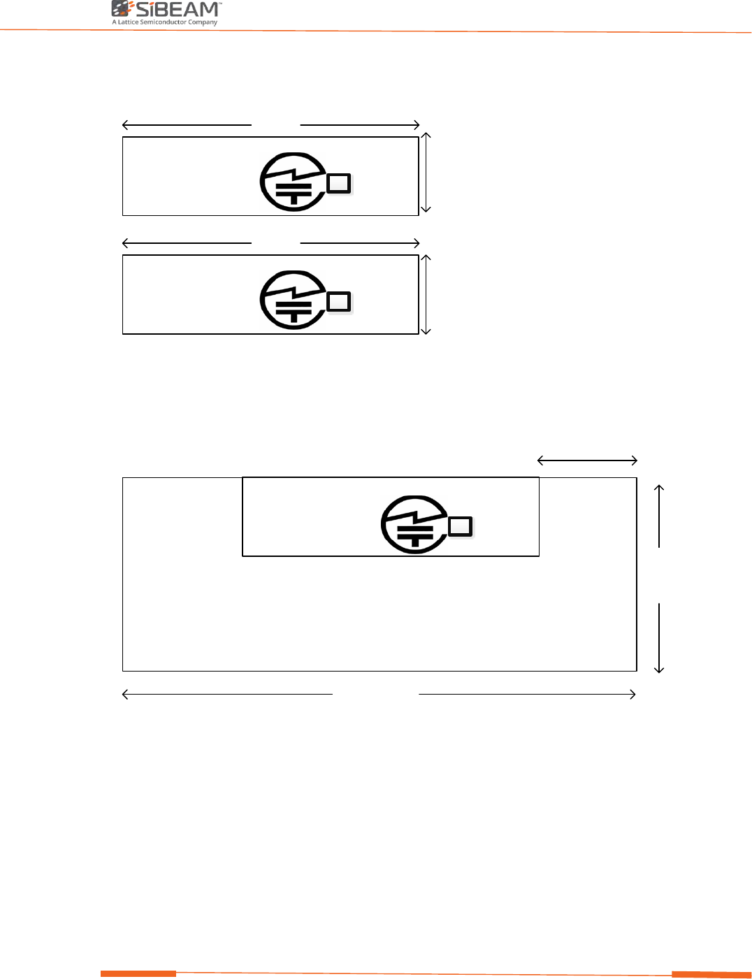
Proposed label
4mm
15mm
4mm
15mm
FCC ID: UK2-MOD621X
IC : 6705A-MOD621X204-630017
Made In China
Sibeam Snap Technology Transceiver module:MOD6213
FCC ID: UK2-MOD621X
IC : 6705A-MOD621X204-630016
Made In China
R
R
Sibeam Snap Technology Transceiver module:MOD6212
Lattice Semiconductor Corp.
Lattice Semiconductor Corp.
Proposed Module Location
9.8 mm
FCC ID: UK2-MOD621X
IC : 6705A-MOD621X
Made In China
R
Sibeam Snap Technology Transceiver module:MOD6213
204-630016
26 mm
5.0 mm
Lattice Semiconductor Corp.

Module Installation Guide
12 ©2017 SiBEAM, Inc., a Lattice Semiconductor company.
All rights reserved. CONFIDENTIAL
Federal Communication Commission Interference Statement
This equipment has been tested and found to comply with the limits for a Class B digital device,
pursuant to Part 15 of the FCC Rules. These limits are designed to provide reasonable
protection against harmful interference in a residential installation. This equipment generates,
uses and can radiate radio frequency energy and, if not installed and used in accordance with
the instructions, may cause harmful interference to radio communications. However, there is
no guarantee that interference will not occur in a particular installation. If this equipment does
cause harmful interference to radio or television reception, which can be determined by
turning the equipment off and on, the user is encouraged to try to correct the interference by
one of the following measures:
● Reorient or relocate the receiving antenna.
● Increase the separation between the equipment and receiver.
● Connect the equipment into an outlet on a circuit different from that to which the receiver is
connected.
● Consult the dealer or an experienced radio/TV technician for help.
FCC Caution: Any changes or modifications not expressly approved by the party responsible for
compliance could void the user’s authority to operate this equipment.
This device complies with Part 15 of the FCC Rules. Operation is subject to the following two
conditions: (1) This device may not cause harmful interference, and (2) this device must accept
any interference received, including interference that may cause undesired operation.
IMPORTANT NOTE:
FCC Radiation Exposure Statement:
This equipment complies with FCC radiation exposure limits set forth for an uncontrolled
environment. This equipment should be installed and operated with minimum distance
20cm between the radiator & your body.
IMPORTANT NOTE:

Module Installation Guide
13 ©2017 SiBEAM, Inc., a Lattice Semiconductor company.
All rights reserved. CONFIDENTIAL
This module is intended for OEM integrator. The OEM integrator is responsible for the
compliance to all the rules that apply to the product into which this certified RF module
is integrated.
Additional testing and certification may be necessary when multiple modules are used.
USERS MANUAL OF THE END PRODUCT:
In the user’s manual of the end product, the end user has to be informed to keep at
least 20cm separation with the antenna while this end product is installed and operated.
The end user has to be informed that the FCC radio-frequency exposure guidelines for
an uncontrolled environment can be satisfied.
The end user has to also be informed that any changes or modifications not expressly
approved by the manufacturer could void the user's authority to operate this equipment.
If the labelling area is small than the palm of the hand, then additional FCC part 15.19
statement is required to be available in the user’s manual: This device complies with
Part 15 of FCC rules. Operation is subject to the following two conditions: (1) this device
may not cause harmful interference and (2) this device must accept any interference
received, including interference that may cause undesired operation.
LABEL OF THE END PRODUCT:
The final end product must be labeled in a visible area with the following "Contains
FCC ID: UK2-MOD621X.
If the labelling area is larger than the palm of the hand, then the following FCC part
15.19 statement has to also be available on the label: This device complies with Part 15
of FCC rules. Operation is subject to the following two conditions: (1) this device may
not cause harmful interference and (2) this device must accept any interference
received, including interference that may cause undesired operation.
This Module may not be integrated into host devices that are addressed for operation
inside airplanes/satellites.

Module Installation Guide
14 ©2017 SiBEAM, Inc., a Lattice Semiconductor company.
All rights reserved. CONFIDENTIAL
Module Installation Guide
15 ©2017 SiBEAM, Inc., a Lattice Semiconductor company.
All rights reserved. CONFIDENTIAL
Industry Canada Interference Statement
This device complies with Industry Canada License-exempt RSS standard(s). Opération is subject
to the following two conditions: (1) this device may not cause interference, and (2) this device
must accept any interference, including interference that may cause undesired operation of the
device.
Le présent appareil est conforme aux CNR d'Industrie Canada applicables aux appareils radio
exempts de licence. L'exploitation est autorisée aux deux conditions suivantes : (1) l'appareil ne
doit pas produire de brouillage, et (2) l'utilisateur de l'appareil doit accepter tout brouillage
radioélectrique subi, même si le brouillage est susceptible d'en compromettre le
fonctionnement.
This radio transmitter (MOD6212/MOD6213) has been approved by Industry Canada to
operate with the antenna types listed below with the maximum permissible gain indicated.
Antenna types not included in this list, having a gain greater than the maximum gain indicated
for that type, are strictly prohibited for use with this device.
Le présent émetteur radio (MOD6212/MOD6213) a été approuvé par Industrie Canada pour
fonctionner avec les types d'antenne énumérés ci-dessous et ayant un gain admissible maximal
d'antenne. Les types d'antenne non inclus dans cette liste, ou dont le gain est supérieur au gain
maximal indiqué, sont strictement interdits pour l'exploitation de l'émetteur.
List of antenna for each module :
Brand
Model Name
Antenna Type
Gain (dBi)
Sibeam
SB6212
Chip
0
Sibeam
SB6213
Chip
2
IMPORTANT NOTE:
IC Radiation Exposure Statement:
This equipment complies with IC RSS-102 radiation exposure limits set forth for an uncontrolled
environment. This equipment should be installed and operated with minimum distance 20cm
between the radiator & your body.
Cet équipement est conforme aux limites d'exposition aux rayonnements IC établies pour un
environnement non contrôlé. Cet équipement doit être installé et utilisé avec un minimum de 20
cm de distance entre la source de rayonnement et votre corps.

Module Installation Guide
16 ©2017 SiBEAM, Inc., a Lattice Semiconductor company.
All rights reserved. CONFIDENTIAL
IMPORTANT NOTE:
This module is intended for OEM integrator. The OEM integrator is responsible for the
compliance to all the rules that apply to the product into which this certified RF module
is integrated.
Additional testing and certification may be necessary when multiple modules are used.
Any changes or modifications not expressly approved by the manufacturer could void
the user's authority to operate this equipment.
USERS MANUAL OF THE END PRODUCT:
In the user’s manual of the end product, the end user has to be informed to keep at
least 20cm separation with the antenna while this end product is installed and operated.
The end user has to be informed that the IC radio-frequency exposure guidelines for an
uncontrolled environment can be satisfied.
The end user has to also be informed that any changes or modifications not expressly
approved by the manufacturer could void the user's authority to operate this equipment.
Operation is subject to the following two conditions: (1) this device may not cause
harmful interference and (2) this device must accept any interference received,
including interference that may cause undesired operation.
LABEL OF THE END PRODUCT:
The final end product must be labeled in a visible area with the following "Contains IC:
6705A-MOD621X". The Host Model Number (HMN) must be indicated at any location
on the exterior of the end product or product packaging or product literature which shall
be available with the end product or online.