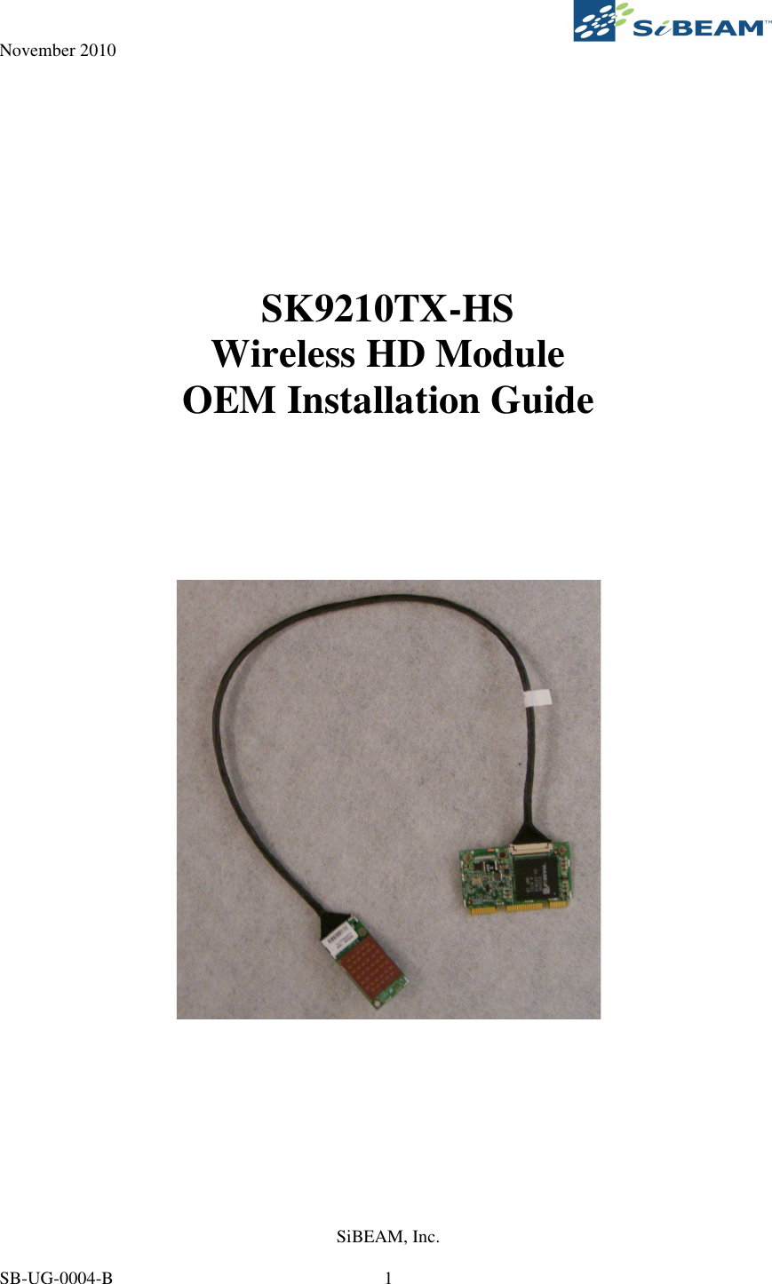
Lattice Semiconductor SK9210TX-HS 60GHz WirelessHD Display Mini Card Transmitter User Manual SB UG 0004 C

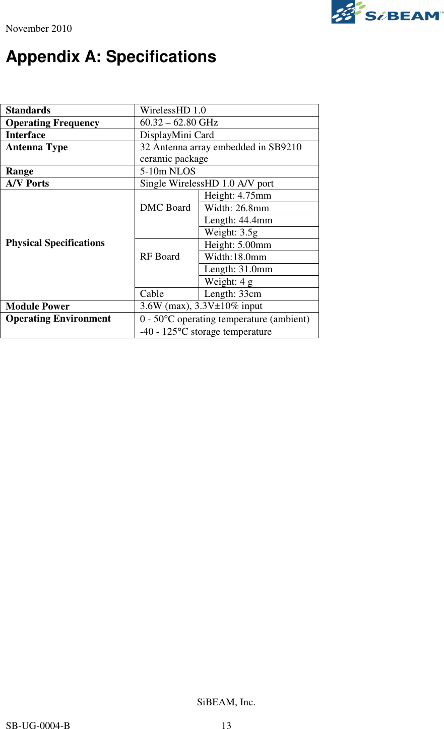
Lattice Semiconductor Corporation 60GHz WirelessHD Display Mini Card Transmitter SB UG 0004 C

User Manual

November 2010     SiBEAM, Inc.   SB-UG-0004-B  1     SK9210TX-HS Wireless HD Module OEM Installation Guide
November 2010     SiBEAM, Inc.   SB-UG-0004-B  2 Table of Contents Table of Contents _______________________________________________________ 2 Purpose of this Document ________________________________________________ 4 Introduction ___________________________________________________________ 4 Terminology _______________________________________________________________ 4 Getting Started _________________________________________________________ 6 SK9210TX-HS Contents______________________________________________________ 6 Unpacking the Module _______________________________________________________ 6 Customer Supplied Equipment ________________________________________________ 6 Setup _________________________________________________________________ 8 WirelessHD Applications Controller (WAC) ________________________________ 10 Appendix A: Specifications ______________________________________________ 13 Appendix B: Interference Statement_______________________________________ 14 Revision History_______________________________________________________ 15
November 2010     SiBEAM, Inc.   SB-UG-0004-B  3 List of Figures Figure 1. SK9210TX-HS Module .................................................................................................................. 6 Figure 2. DisplayMini Card............................................................................................................................ 9 Figure 3. RF Board......................................................................................................................................... 9 Figure 4. WAC Status Screen....................................................................................................................... 10 Figure 5. WAC Network Screen................................................................................................................... 11 Figure 6. WAC Info Screen.......................................................................................................................... 11 Figure 7. WAC Advanced Screen ................................................................................................................ 12
November 2010     SiBEAM, Inc.   SB-UG-0004-B  4 Purpose of this Document  This document provides customers with all the information necessary to allow them to utilize SiBEAM’s SK9210TX-HS WirelessHD module. It takes the user through an explanation of the system components, operation and bring-up while also describing the basic system configuration and diagnostics.    It  is  expected  that  user  of  the SK9210TX-HS  have  some  basic  knowledge  of the  WirelessHD  (WiHD) specification.    If  not,  the  user  should  review  the  major  operation  points  of  the  specification  to  better understand the operation of the module.  Introduction  The SK9210TX-HS module provides a complete WiHD solution.  The module is meant to be placed inside a Notebook PC’s DisplayMini Card (DMC) socket.  Alternatively, the SK9210TX-HS may be placed into a DMC adapter board provided by SiBEAM (SK9200DMCA).    The  setup  of  the  SK9210TX-HS  is  simple.    Inserting  the  DMC  board  into  the  DMC  socket  and  then properly placing the RF module in position followed by powering up the PC.  A software applications tool, the WirelessHD Applications Controller (WAC), is provided to control the module in the PC.  Terminology The following terms are used thru out this document.  Audio Video Control (AVC) – the command structure defined in the WiHD specification used between WiHD stations and coordinator.  Consumer Electronics Control bus (CEC) – the control bus defined in the HDMI specification which is used to pass command and other information between HDMI connected devices.  DMCA  (DisplyMini  Card  Adapter)  Board  –  a  reference  adapter  board  with  USB  and  HDMI  inputs which are provided to a DMC socket on board.  An SK9210TX-HS can be plugged into this socket and the adapter board may be plugged into any PC with USB and HDMI outputs to create a functioning solution.  Embedded  CPU  –  the  32-bit  embedded  CPU  inside  the  SB9220  or  SB9221  that  runs  all  the  WiHD protocol management between a source and sink device.  Host  Microcontroller  –  the  Atmel  AT91SAM7S  series  microcontroller  on  the  HDMI  Interface  board which provides over control of the WiHD board and standalone operation.  In development, the majority of the code running in this microcontroller will be ported to the host processor which runs the system.  Line of Sight (LOS) - uninterrupted or blocked transmission from the WiHD Transmitter Module to the WiHD Receiver Module.  Non Line of Sight (NLOS) - a transmission from the WiHD Transmitter Module which is not LOS and travels by bouncing off one or more objects before reaching the WiHD Receiver Module.  SBAM2 – SiBEAM’s Application Manager tool for the PC to monitor status, set configuration and control other  parameters  of  the  WiHD  Transmitter  and  Receiver  Modules.    SBAM2  is  used  for  the  second generation SK9200 kits.
November 2010     SiBEAM, Inc.   SB-UG-0004-B  5 Sink – a system which receives and renders A/V from a source device.  This typically is a DTV or similar device.    The  WiHD  Receiver  Module  can  be  considered  a  wireless  A/V  sink  when  it  is  connected  to another A/V sink over HDMI.  Sink devices may be a video sink, audio sink or audio/video (A/V) sink.  SK9210TX-HS – the WirelessHD module including the DMC board, cable and RF board.  Full schematics, BOM and layout files are available.  Source – a system providing A/V to a sink device.  This may be a DVD player, Set Top Box or A/V signal generator.  The WiHD Transmitter Module can be considered a wireless A/V source when it is connected to another A/V source over HDMI.  Source devices may be a video sources, audio source or audio/video (A/V) source.  The SK9210TX-HS is a source device.  WAC (WirelessHD Applications Controller)  – Application  tool which  runs  on the  PC to control  and monitor the SK9210TX-HS in a Notebook PC.   WiHD Receiver Board – WiHD board which includes the SB9221 Network Processor and SB9211 RF HRRX Transceiver.  WiHD Transmitter Board – WiHD board which includes the SB9220 Network Processor and SB9210 RF HRTX Transceiver.  WVAN  –  Wireless  Video  Area  Network.    A network  consisting  of  at  least  one  WiHD  enabled  device which  acts  as  a  WiHD  coordinator  for  the  network.    Additional  stations  may  join  or  be  added  to  the WVAN.
November 2010     SiBEAM, Inc.   SB-UG-0004-B  6 Getting Started SK9210TX-HS Contents The following items are included in a SK9210TX-HS module:   • DMC board • Cable • RF board  Unpacking the Module The module will come with the two boards already connected.  The only action by the user upon opening the packaging is to locate the DMC board and the RF board as shown in Figure 1.    Figure 1. SK9210TX-HS Module  Customer Supplied Equipment  The customer should have available a Notebook PC with a DMC slot available and accessible.  The RF board is typically mounted on the backside (outward facing) of the LCD panel with the cable running thru the hinge assembly.  RF board shall be positioned to provide at least 0.65 cm from the end user.  0.65 cm distance  is  measured  by  positioning  the  display  section  of  notebook/Netbook/Laptop  computers perpendicular  to  the  keyboard  section.   Measure  the  distance  from  the  nearest  point  of  antenna  to  the bottom of  host.  The PC should  be running the 64-bit  version of Windows 7.  The SK9210TX-HS can support a number of audio and video formats as listed in Table 1 and Table 2.  Also included but not listed are 3D video formats.  The host equipment must be labeled with the following text: “Contains TX module FCC ID: UK2-SK9210TX-HS” and /or “Contains TX module IC: 6705A-SK9210TXHS”.  The customer will also need a WirelessHD enabled sink device.  There are a number of options for this available on the market or they may use SiBEAM’s SK9200 reference design with the Rx module.
November 2010     SiBEAM, Inc.   SB-UG-0004-B  7  Table 1. Supported Video Formats  Video Format  Vertical Refresh  Color Space  Sampling  Bits/Pixel 4:2:2  24/30-bits YCbCr  4:4:4  24/30-bits  480i  59.94/60Hz RGB  4:4:4  24/30-bits 4:2:2  24/30-bits YCbCr  4:4:4  24/30-bits  480p  59.94/60Hz RGB  4:4:4  24/30-bits 4:2:2  24/30-bits YCbCr  4:4:4  24/30-bits  576i  50Hz RGB  4:4:4  24/30-bits YCbCr  4:2:2  24/30-bits YCbCr  4:4:4  24/30-bits  576p  50Hz RGB  4:4:4  24/30-bits 4:2:2  24/30-bits YCbCr  4:4:4  24/30-bits 50Hz RGB  4:4:4  24/30-bits 4:2:2  24/30-bits YCbCr  4:4:4  24/30-bits   720p 59.94/60Hz RGB  4:4:4  24/30-bits 4:2:2  24/30-bits YCbCr  4:4:4  24/30-bits 50Hz RGB  4:4:4  24/30-bits 4:2:2  24/30-bits YCbCr  4:4:4  24/30-bits   1080i 59.94/60Hz RGB  4:4:4  24/30-bits 4:2:2  24/30-bits YCbCr  4:4:4  24/30-bits 23.976/24Hz RGB  4:4:4  24/30-bits 4:2:2  24/30-bits YCbCr  4:4:4  24/30-bits 50Hz RGB  4:4:4  24-bits 4:2:2  24/30-bits YCbCr  4:4:4  24-bits     1080p 59.94/60Hz RGB  4:4:4  24/30-bits VGA  60Hz  RGB  4:4:4  24/30-bits WVGA  60Hz  RGB  4:4:4  24/30-bits SVGA  60Hz  RGB  4:4:4  24/30-bits XGA  60Hz  RGB  4:4:4  24/30-bits SXGA  60Hz  RGB  4:4:4  24/30-bits WSXGA+  60Hz  RGB  4:4:4  24/30-bits
November 2010     SiBEAM, Inc.   SB-UG-0004-B  8 Table 2. Supported Uncompressed Audio Formats  Audio Sample Rate, F's 2/6/8-channels  2-channel Multiples of Fs  32 kHz  44.1 kHz  48 kHz  88.2 kHz  96 kHz  176.4 kHz  192 kHz 128  4.096  5.645  6.144  11.290  12.288  22.579  24.576 256  8.192  11.290  12.288  22.579  24.576  45.158  49.152 384  12.288  16.934  18.432  33.864  36.864 512  16.384  22.579  24.576  45.158  49.152      Setup  The setup for the SK9210TX-HS is fairly straight forward.  Step 1:  Make sure all power is off on the Notebook PC and remove the battery.  Open up the Notebook PC so that DMC socket is accessible.  This may require the removing of other boards/screws and plastic coverings.     Step 2:  Insert the DMC board into the DMC socket.  The socket is keyed so the board can only fit in on direction.  Step 3:  Install the RF board into position.  This typically will also involve opening up the LCD panel to provide  access  to  the  RF  board  location.    Depending  on  the  PC  configuration,  it  may  be  necessary  to unplug the cable between the DMC and RF board to do the installation.  It’s typically easiest to unplug the cable  from  the  RF  board  and  route  the  cable  around  other  boards  and  thru  the  hinge  assembly.    If unplugged, plug back in the cable between the DMC and RF board once the RF board is in position.  Step 4:  Close up the PC installing all boards, cables and plastic enclosures.   Step 5:  Power on the Notebook PC.  Make sure that the PC comes up with normal operation as expected.  Step 6:  Install the WAC as described in the following section.  Step 7:  Place the Notebook PC within range of a WiHD sink device (<10m) and power on the sink device.  Step 8:  Start  the  WAC  and  go  to  the  Network  tab.    Select  Refresh  List  to  see  the  list  of  available WVAN’s.  The WVAN for the sink device powered up should be listed.   Step 8:  Select the appropriate WVAN and press the Connect button.  The A/V should start playing on the sink device after approximately 8-15 seconds.
November 2010     SiBEAM, Inc.   SB-UG-0004-B  9      Figure 2. DisplayMini Card     Figure 3. RF Board
November 2010     SiBEAM, Inc.   SB-UG-0004-B  10 WirelessHD Applications Controller (WAC)  The WirelessHD Applications Controller (WAC) is provided for end user control over the SK9210TX-HS.  Thru the WAC, the end user is able to connect/disconnect from a WVAN, see operating performance and update code on the module.  Figure 4 shows the Status screen of the WAC.  In this screen the user is able to see the signal strength achieved, if the module is Associated in a WVAN or if there is an active Connection.  The signal strength can be used to provide guidance should there be bad image quality and the user may use this information to move the source or sink to a better location for reception.    Figure 4. WAC Status Screen  The Network screen is shown in Figure 5.  This is the main screen used to make an active connection to a display.    In  this  screen  the  user  can  see  the  available  WVAN’s  and  select  and  connect  to  a  particular WVAN.  The HR and LR channel used by the WVAN is also shown.
November 2010     SiBEAM, Inc.   SB-UG-0004-B  11   Figure 5. WAC Network Screen  The Info screen of the WAC (Figure 6) is used to show what A/V formats are being transmitted and which code versions are running on the module.  The code versions will consist of embedded code run on the embedded CPU of the SB9220 and the host code run on the Atmel host microcontroller.     Figure 6. WAC Info Screen  The Advanced screen of the WAC (Figure 7) is used to for code updates.  When selected, additional pop-up windows will ask for the location of the new code to update and then start the update process.  The code update time takes approximately 5-7 minutes.
November 2010     SiBEAM, Inc.   SB-UG-0004-B  12   Figure 7. WAC Advanced Screen
November 2010     SiBEAM, Inc.   SB-UG-0004-B  13 Appendix A: Specifications    Standards  WirelessHD 1.0 Operating Frequency  60.32 – 62.80 GHz Interface  DisplayMini Card  Antenna Type  32 Antenna array embedded in SB9210 ceramic package Range  5-10m NLOS A/V Ports  Single WirelessHD 1.0 A/V port Height: 4.75mm Width: 26.8mm Length: 44.4mm  DMC Board Weight: 3.5g Height: 5.00mm Width:18.0mm Length: 31.0mm  RF Board Weight: 4 g     Physical Specifications Cable  Length: 33cm Module Power  3.6W (max), 3.3V±10% input Operating Environment  0 - 50°C operating temperature (ambient) -40 - 125°C storage temperature
November 2010     SiBEAM, Inc.   SB-UG-0004-B  14 Appendix B: Interference Statement  USA-Federal Communications Commission (FCC) This equipment has been tested and found to comply with the limits for a Class B digital device, pursuant to  Part  15  of  FCC  Rules.  These  limits  are  designed  to  provide  reasonable  protection  against  harmful interference in a residential installation. This equipment generates, uses, and can radiate radio frequency energy. If not installed and used in accordance with the instructions, it may cause harmful interference to radio  communications.  However,  there  is  no  guarantee  that  interference  will  not  occur  in  a  particular installation.  1. This  device  complies  with  Part  15  of  the  FCC  Rules.  Operation  is  subject  to  the  following  two conditions: (1) this device may not cause harmful interference, and  (2) this device must accept any interference received, including interference that may cause undesired operation. 2. This product does not contain any user serviceable components. Any unauthorized product changes or modifications will invalidate warranty and all applicable regulatory certifications and approvals. 3. Caution: Exposure to Radio Frequency Radiation: The installer of this radio equipment must ensure that the antenna (RF board ) is located at least 0.65 cm to the user and pointed away from the end user.  The antenna(s) used for this transmitter must not be collocated or operating in conjunction with any other  antenna or transmitter  within  a host  device,  except  in accordance  with  FCC multi-transmitter product procedures. 4. Caution:  User  is  cautioned  that  changes  or  modifications  not  expressly  approved  by  the  party responsible for compliance could void the user's authority to operate the equipment.     Canada – Industry Canada (IC)  This  device  complies  with  RSS  210  of  Industry  Canada.  Operation  is  subject  to  the  following  two conditions: (1) this device may not cause interference, and (2) this  device must accept any interference, including interference that may cause undesired operation of this device.”  L ‘ utilisation de ce dispositif est autorisée seulement aux conditions suivantes : (1) il ne doit pas produire de brouillage et (2) l’ utilisateur du dispositif doit étre prêt à accepter tout brouillage radioélectrique reçu, même si ce brouillage est susceptible de compromettre le fonctionnement du dispositif.  The term "IC" before the equipment certification number only signifies that the Industry Canada technical specifications were met. To reduce potential radio interference to other users, the antenna type and its gain should be so chosen that the equivalent isotropically radiated power (EIRP) is not more than that required for successful communication. To prevent radio interference to the licensed service, this device is intended to be operated indoors and away from windows to provide maximum shielding. Equipment (or its transmit antenna) that is installed outdoors is subject to licensing.  Pour  empecher  que  cet  appareil  cause  du  brouillage  au  service  faisant  l'objet  d'une  licence,  il  doit  etre utilize a l'interieur et devrait etre place loin des fenetres afin de Fournier un ecram de blindage maximal. Si le matriel (ou son antenne d'emission) est installe a l'exterieur, il doit faire l'objet d'une licence.  Caution: Exposure to Radio Frequency Radiation. The installer of this radio equipment must ensure that the antenna (RF board) is located at least 0.65 cm to the user and  pointed away from the end user such that it does not emit RF field in excess of Health Canada limits  for  the  general  population;  consult  Safety  Code  6,  obtainable  from  Health  Canada’s  website www.hcsc.gc.ca/rpb.
November 2010     SiBEAM, Inc.   SB-UG-0004-B  15  Revision History Revision  Date  Change A  11/1/10  Initial release. B  11/10/10  Updated  cover  page,  clarification  of  Customer  Supplied Equipment and updated Appendix B. C  11/11/10  Updated Appendix B Interference statements                                                           SiBEAM, Inc. 555 N. Mathilda Ave. Sunnyvale, CA 94085 408-245-3120 Phone 408-245-3120 Fax  Copyright © 2010 SiBEAM Japan K.K. Shinjuku Park Tower N30F 3-7-1 Shinjuku-ku,  Tokyo 163-1030 Japan +81-3-5326-3085 Phone +81-3-5326-3001Fax  SiBEAM Korea #1906, 19F Parkview Tower 6  Jungja-Dong,  Bundang-Gu, Sungnam-Si, Gyunggi-Do +82-31-711-2336 Phone +82-31-783-2209 Fax

Navigation menu