Launch Tech CRP429TPMS TPMS Activation and Diagnostic Tool User Manual
Launch Tech Co., Ltd. TPMS Activation and Diagnostic Tool Users Manual
UserManual.wiki
>
Launch Tech
>
CRP429TPMS User Manual
Users Manual
Navigation menu
Upload a User Manual
Namespaces
Wiki Guide
HTML
PDF
Info
Views
User Manual
Discussion / Help
Navigation
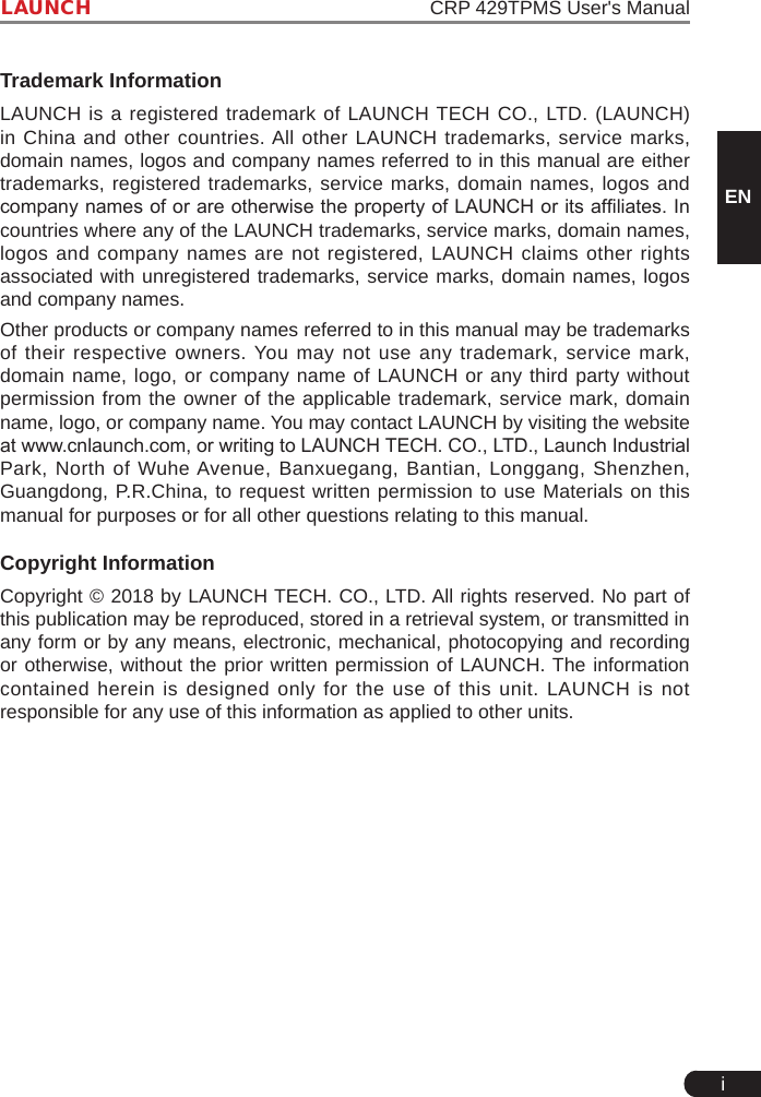
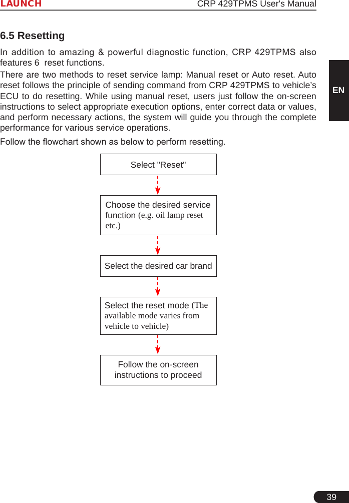
![10LAUNCH CRP 429TPMS User's Manual4. Initial Use4.1 Charging CRP 429TPMSThere are two charging methods available:Via Charging Cable: Plug one end of the included charging cable into the DC-IN port of the tool, and the other end to the external DC power.Via Diagnostic Cable: Insert one end of the diagnostic cable into the DB-15 connector of the tool, and the other end to the vehicle’s DLC.Once the charging LED illuminates solid green, it indicates that the battery is fully charged.4.2 Getting StartedIf it is the first time you have used this tool, you need to make some system settings.1. Press the [Power] button to power it on.2. The screen displays a welcome page. Tap “Start” to go to next step.Figure 4-1](https://usermanual.wiki/Launch-Tech/CRP429TPMS/User-Guide-4023650-Page-16.png)
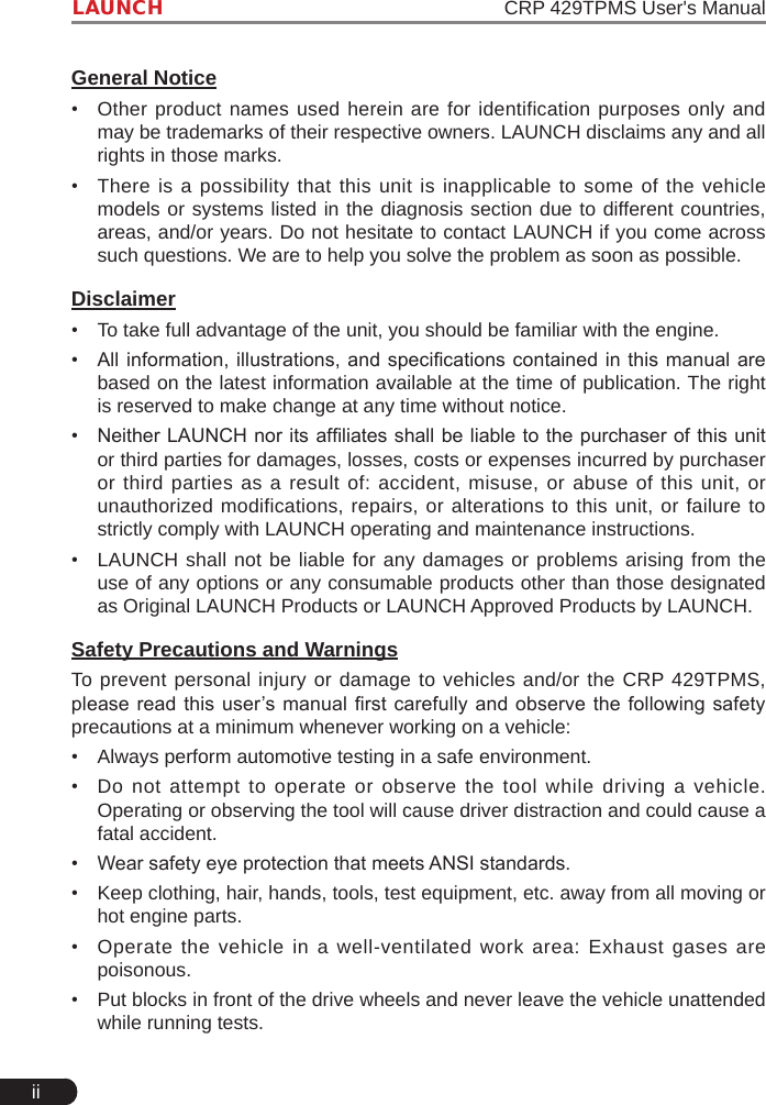
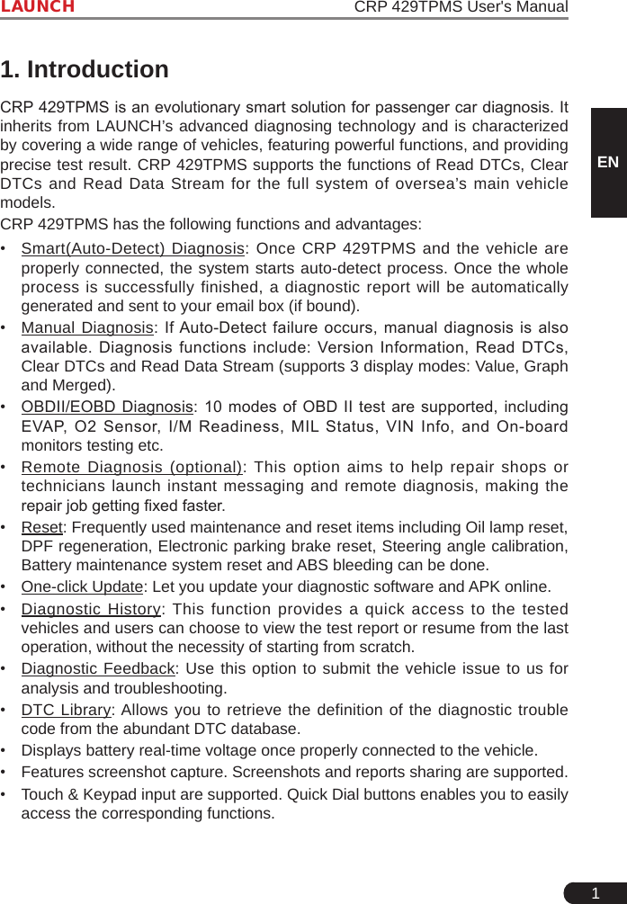
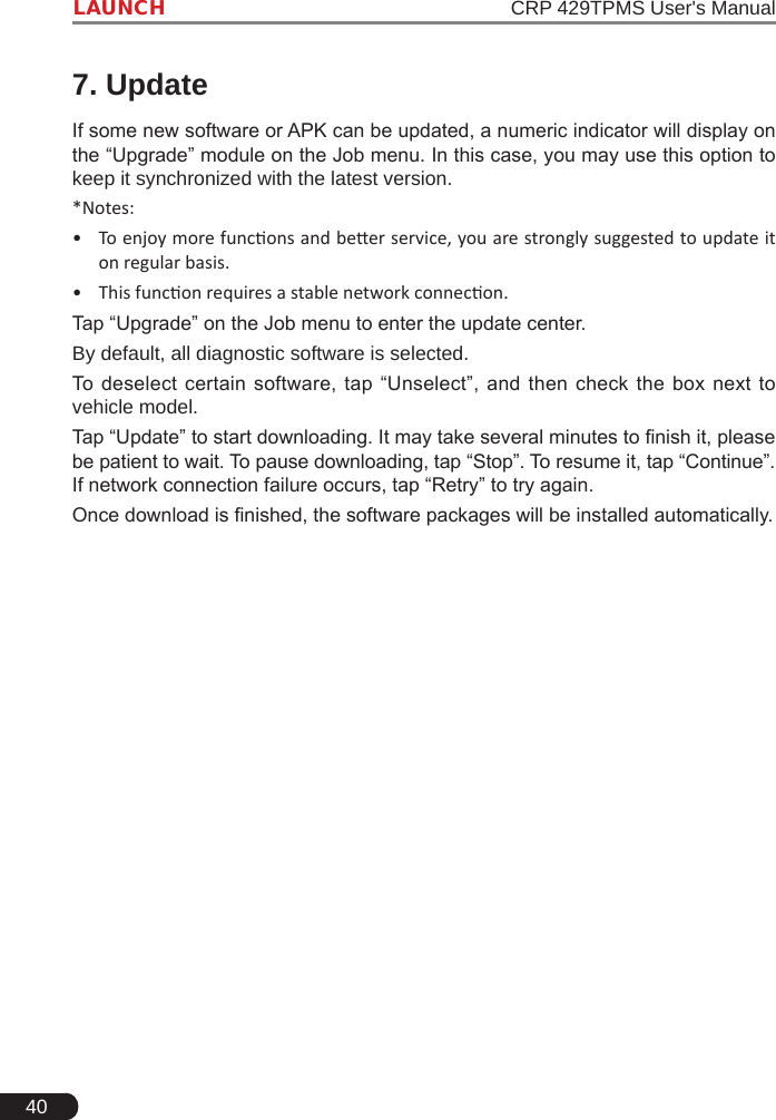
![35LAUNCH CRP 429TPMS User's ManualENFig. 6-12Combine: Tap it, a pull-down list of the data stream items appears on the screen. Select the necessary items and the screen will display the waveforms corresponding to these items immediately.Report: To save the current data as a diagnostic report. All diagnostic reports can be accessed from “Data” -> “Diagnostic Report”.Record: Tap to start recording diagnostic data for future playback and analysis. The saved le follows the naming rule: It begins with vehicle type, and then the record starting time and ends with .x431 (To differentiate between les, please congure the accurate system time). All diagnostic records can be replayed from “Data” -> “Diagnostic Record”.6.3 OBDII DiagnosisThis option presents a quick way to check for DTCs, isolate the cause of the illuminated Malfunction Indicator Lamp (MIL), check monitor status prior to emissions certification testing, verify repairs, and perform a number of other services that are emission-related.On the Job menu, press [OBD II] to enter system, the screen will automatically jump to gure 6-13:](https://usermanual.wiki/Launch-Tech/CRP429TPMS/User-Guide-4023650-Page-41.png)
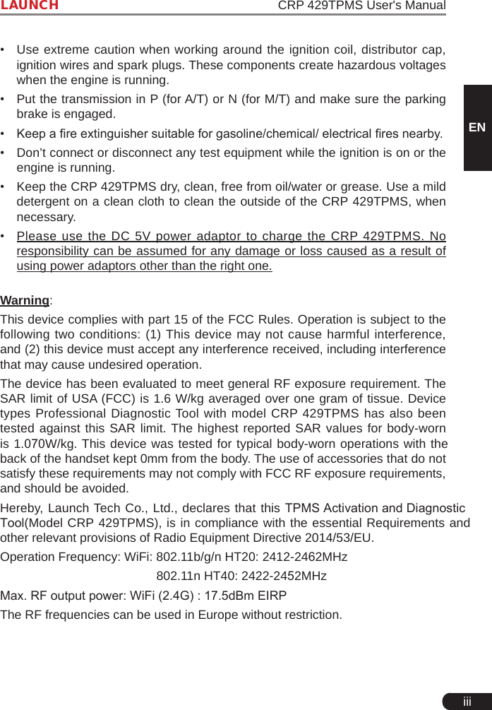
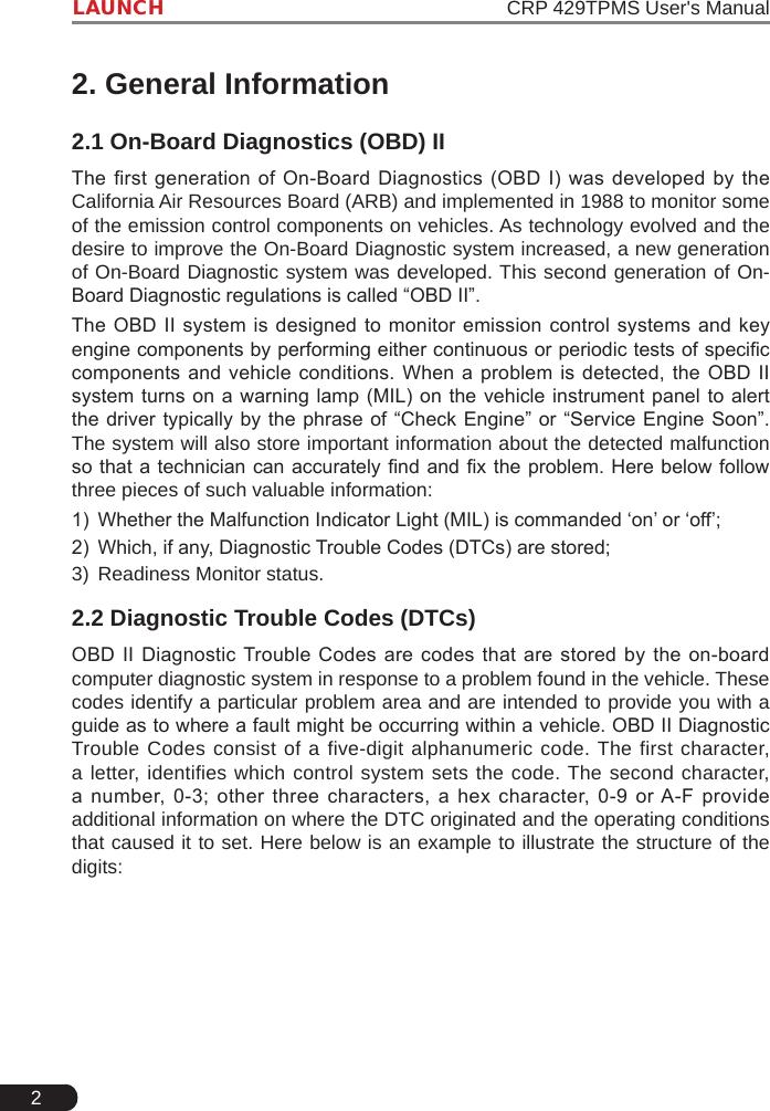
![36LAUNCH CRP 429TPMS User's Manual Figure 6-13 Figure 6-14Tap [OK], a screen similar to Figure 6-14 will appear.It mainly includes the following functions:1. Read CodesThis option is used to identify which section of the emission control system has malfunctioned.2. Erase CodesAfter reading the retrieved codes from the vehicle and certain repairs have been carried out, you can use this function to erase the codes from the vehicle. Before performing this function, please be sure the vehicle’s ignition key is in the ON position with the engine off.*Notes:• Before performing this funcon, make sure to retrieve and record the trouble codes.• After clearing, you should retrieve trouble codes once more or turn ignition on and retrieve codes again. If there are sll some trouble codes in the system, please troubleshoot the code using a factory diagnosis guide, then clear the code and recheck.3. I/M Readiness](https://usermanual.wiki/Launch-Tech/CRP429TPMS/User-Guide-4023650-Page-42.png)
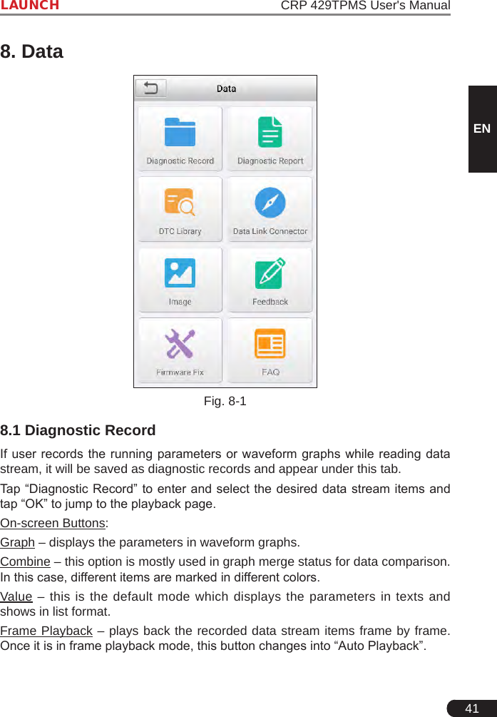
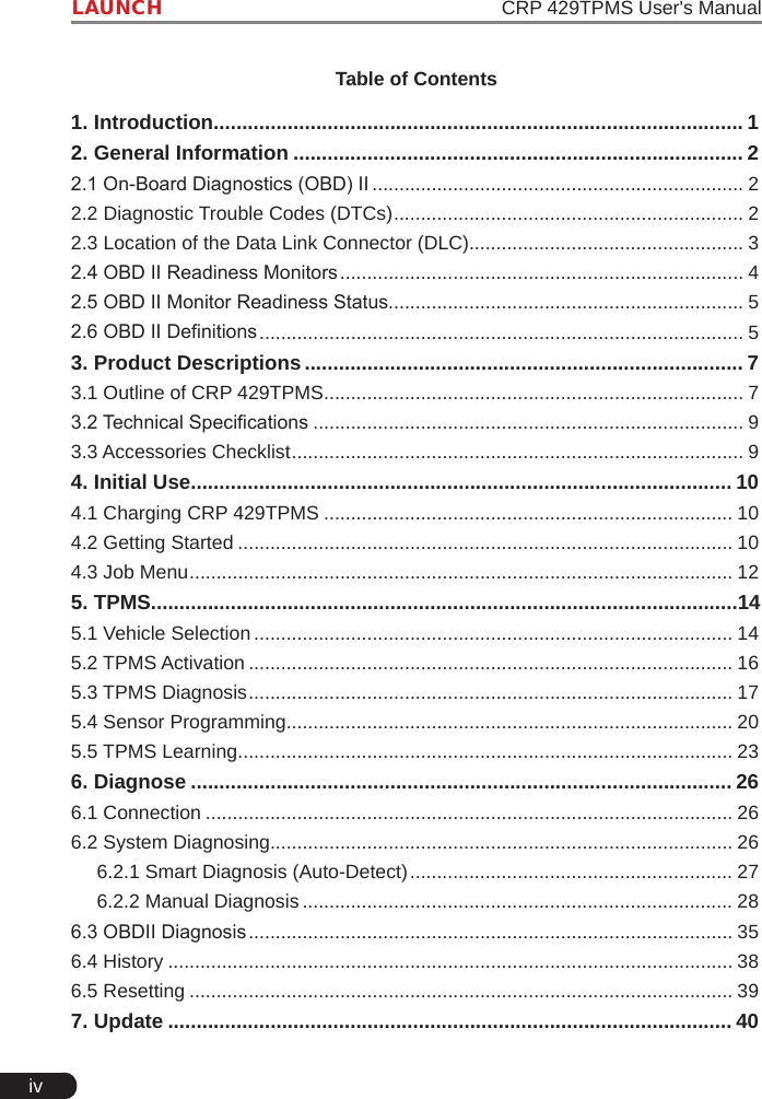
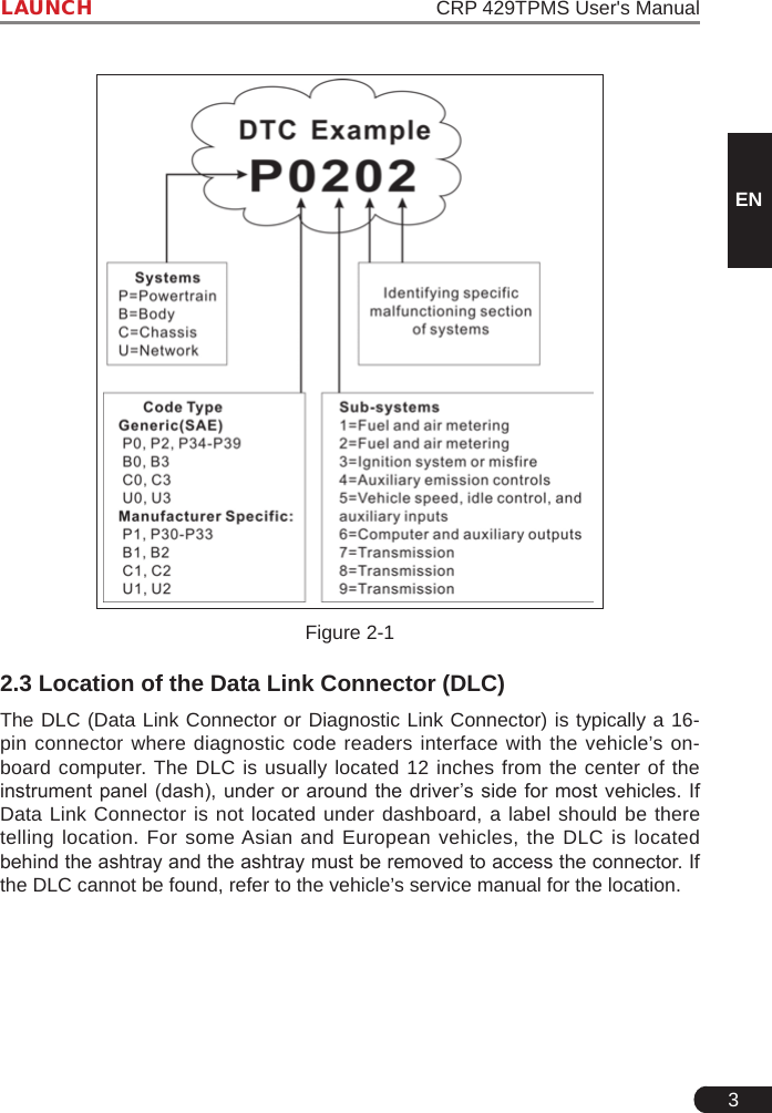
![42LAUNCH CRP 429TPMS User's Manual8.2 Diagnostic ReportThis module stores all diagnostic reports generated in process of vehicle diagnosis. All the diagnostic reports are sorted by Date and Make. If there are too many reports stored, tap (Search) to lter and quickly locate it. • To select certain report, just check the box at the right lower corner of the report. To select all reports, tap “Select All”. To deselect all, tap “Unselect”.• Tap it to view its details.• Select the desired report and then tap “Delete” to delete it.8.3 DTC LibraryThis option helps you to nd the location of the vehicle’s DLC.Fig. 8-2Swipe the screen upwards/downwards to alter the value, then press [OK] button, the screen will display denition of the DTC.](https://usermanual.wiki/Launch-Tech/CRP429TPMS/User-Guide-4023650-Page-48.png)