Launch Tech DS401 Automotive Diagnosis Terminal User Manual
Launch Tech Co., Ltd. Automotive Diagnosis Terminal Users Manual
Users Manual
LAUNCH
Quick Start Guide
CRP329
Product Profile
CRP329 System
CRP329 is a stylish Android-based diagnostic device developed by LAUNCH. It inherits from
LAUNCH's advanced diagnosing technology and is characterized by covering a wide range of
vehicle models, featuring powerful functions, and providing precise test result.
Through simple wireless communication, it achieves full car model and full system vehicle
trouble diagnosis. In addition, CRP329 supports network connection, one-click update and all
kinds of resetting operations(including oil lamp reset etc).
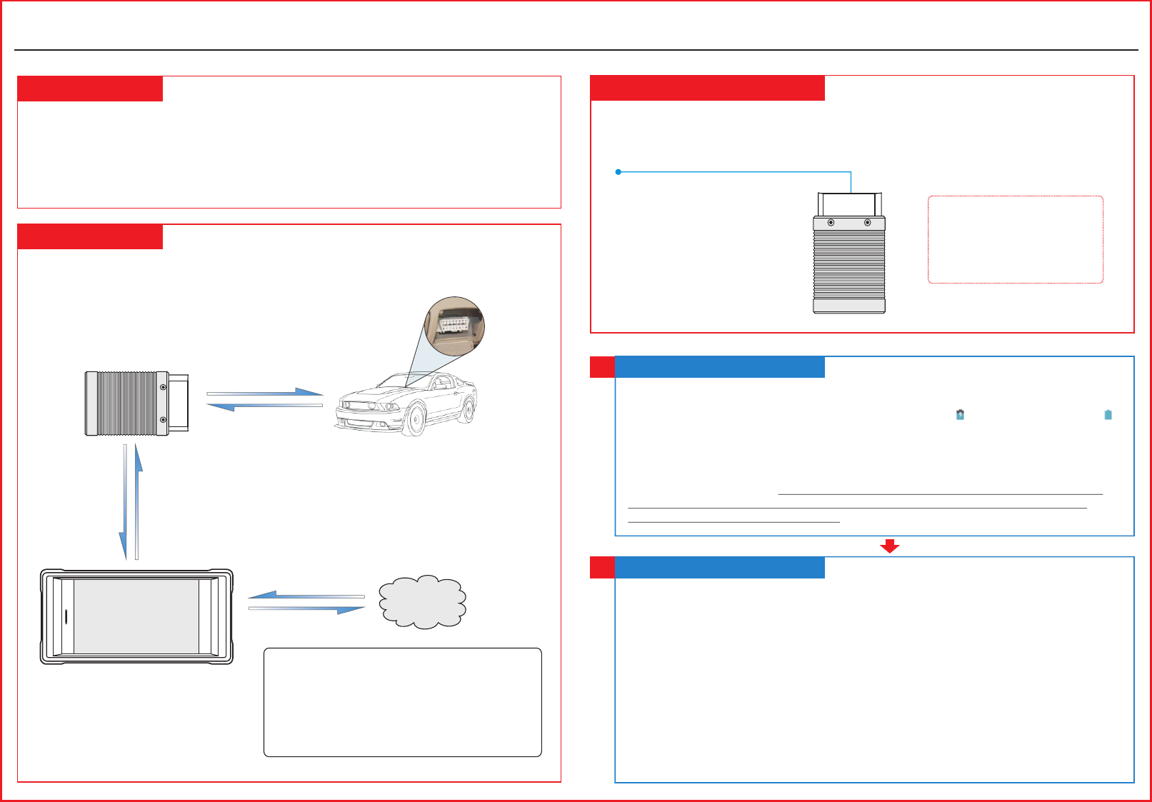
VCI Connector
OBD II 16pin connector
(For connecting to vehicle’s DLC)
The VCI connector only applies to the passenger vehicles of 12V. It can be installed on the
OBD II vehicle’s DLC directly or via the extension cable.
The CRP329 system is mainly composed of CRP329 tablet and VCI connector. The following
illustration explains how the CRP329 tablet works with the VCI connector.
(For details on how to
connect, please refer to
Section 4 “Preparation
& Connections”.)
To proceed one of the following operations, you need
to make network connection (See Section 2
“Network Setup” for details):
Register & activate CRP329, update the diagnostic
software & APK
Work on golo module
Surf the Internet
*Note: Remember to remove the
VCI connector from the DLC
and re-insert it into the slot on
the back of the tablet after use to
avoid loss.
Charging & Turning On
1
1. Connect the power adaptor to the Universal Serial BUS port of the tool.
2. If the tool is being charged, a charging indicator displays . Once the indicator turns ,
charging is complete.
3. Pressing the POWER button will start the tool and enter the home screen.
Note:On first use of the tool, or if the tool remains idle for a long period of time, there may be
insufficient battery power to start the tool. Please charge for a minimum of 5 minutes before
attempting to turn it on again. Please use the power adaptor included within the kit to charge the
tool. No responsibility can be assumed for any damage or loss caused as a result of using any
power adaptor other than the one supplied.
Network Setup
2
CRP329 supports WLAN connection. To enable you to surf the Internet, register App,
launch golo module and update the diagnostic software etc, please follow the steps
below to configure the network:
1. On the home screen, tap “Settings” > WLAN.
2. Slide the WLAN switch to ON, the system starts searching for available WLAN
networks.
3. Select a wireless network. If the chosen network is open CRP329 will connect
automatically, if the selected network is encrypted, a network password will need to be
entered.
4. When “Connected” appears, it indicates the tablet is properly connected to the
Internet.
*Note: when WLAN is not required this should be disabled to conserve battery power.
CRP329 Tablet
(Works as the central processor and
monitor for analyzing vehicle data
and indicating the test result.)
VCI Connector
(Works as the vehicle
communication interface device
for accessing the vehicle data.)
Vehicle
To Vehicle’s DLC
(Sending the vehicle data to CRP329 tablet)
Internet
DS401
LAUNCH
All illustrations are for reference purpose only and this Quick Start Guide is subject to change without notice.
1. Launch App -> 2. Create an App Account -> 3. Activate VCI Connector -> 4. Download
Diagnostic Software)
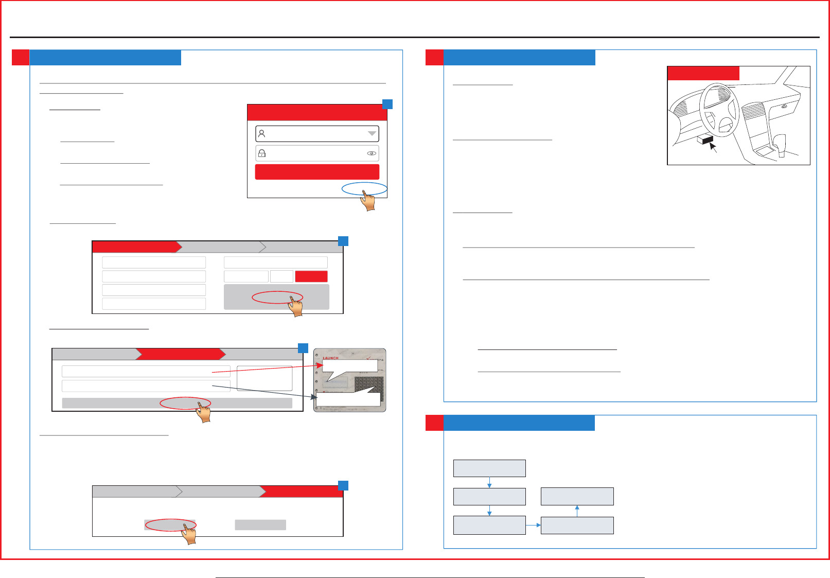
Register & Update
3
1. Launch App: Tap the application icon to
launch it. Tap “Login” on the right upper
corner of the screen.
a.For initial use, tap “New registration” to
open a sign-up page, refer to steps 2~4.
b.If you have an account, tap “Login” to
login directly.
c.If you forgot the password, tap “Retrieve
password” to retrieve it.
Login
Username
Password
Retrieve password New Registration
Login
2. Create Account: In Fig. B, fill in each field and tap “Register” to go to step 3. (Note: To
obtain more functions and better service, please enter the real information.)
3. Activate VCI Connector: In Fig. C, input the Product S/N and Activation Code (can be
obtained from the password envelope), and then tap “Activate”.
4. Update Diagnostic Software: Tap “Yes” in Fig. D to enter diagnostic software
download screen. (Note: To download the software later, tap “No”. In this case, tap
“Software Upgrade” on the function menu to download it.)
Tap “Update” to download and install the diagnostic software.(Note: Be sure that the tool
has a strong WLAN connection during downloading.)
Preparation & Connections
4
A
1. Preparation
1) Switch the ignition on.
2) The vehicle battery voltage should be 9-14V.
3) Throttle should be in a closed position.
2.Locate vehicle’s DLC
The DLC(Data Link Connector) provides standard
16 pins and is generally located on driver’s side,
about 12 inch away from the center of dashboard.
See Figure DLC Location. If DLC is not equipped under dashboard, a label indicating its
position will be given. In case no DLC is found, please refer to Automobile Repair Manual.
3.Connection
Select the desired diagnostic connector according to the vehicle DLC type and then follow
the steps below to proceed:
1.For vehicles equipped with an OBD II management system, plug the VCI connector into
the vehicle’s DLC directly or use the OBD II extension cable to connect the VCI
connector and the DLC.
2.For vehicles not equipped with an OBD II management system, do the following:
1). Select the corresponding non-16pin connector.
2). Plug the non-16pin end of the connector into the DLC socket, then connect the other
end to the OBD I adaptor, and then tighten the captive screws.
3). Connect the other end of the adaptor to the VCI connector.
4). To supply power to OBD I adaptor from:
A. Battery Clamps Cable(optional): Connect one end of the battery clamps cable to
vehicle's battery, and the other end to the power jack of OBD I adaptor, Or
B. Cigarette Lighter Cable(optional): Connect one end of the cigarette lighter cable
to vehicle's cigarette lighter receptacle, and the other end to the power jack of OBD
I adaptor.
Near center of dashboard
DLC Location
Start Diagnostics
5
For new users, follow the sequence below to start a new diagnostic session.
*Notes:
1. To start diagnosing a vehicle, you have to activate
the VCI connector and download the diagnostic
software. For details, refer to Section 3 “Register
& Update” in this Quick Start Guide.
2. All software is updated from time to time. To
enjoy more better service and functions, you are
suggested to keep updated with the latest version.
Quick Start Guide
CRP329
Tap “Diagnostic”
Select vehicle model
Select test system
Select test function
Select software
version
CAPTCHA
5169
*
Select Country
*
Email
*
Confirm Password
*
Password
*
Username
*
CAPTCHA
Create an Account Activate Connector Finish Registration
Register
Create an Account Finish RegistrationActivate Connector
Serial Number
Wher e is my activ ation cod e?
Activate
Activation Code
Product S/N
Activation Code
Create an Account Activate Connector Finish Registration
Congratulations! You have registered successfully. Do you download vehicle software now?
Yes No
B
C
D
1. This device complies with Part 15 of the FCC Rules. Operation is subject to the following two
conditions:
(1) This device may not cause harmful interference.
(2) This device must accept any interference received, including interference that may cause
undesired operation.
2. Changes or modifications not expressly approved by the party responsible for compliance could
void the user's authority to operate the equipment.
NOTE: The manufacturer is not responsible for any radio or TV interference caused by
unauthorized modifications to this equipment. Such modifications could void the user’s authority
to operate the equipment.
NOTE: This equipment has been tested and found to comply with the limits for a Class B digital
device, pursuant to part 15 of the FCC Rules. These limits are designed to provide reasonable
protection against harmful interference in a residential installation.
This equipment generates uses and can radiate radio frequency energy and, if not installed and
used in accordance with the instructions, may cause harmful interference to radio communications.
However, there is no guarantee that interference will not occur in a particular installation. If this
equipment does cause harmful interference to radio or television reception, which can be
determined by turning the equipment off and on, the user is encouraged to try to correct the
interference by one or more of the following measures:
- Reorient or relocate the receiving antenna.
- Increase the separation between the equipment and receiver.
-Connect the equipment into an outlet on a circuit different from that to which the receiver is
connected.
-Consult the dealer or an experienced radio/TV technician for help
This equipment complies with FCC RF radiation exposure limits set forth for an uncontrolled
environment.