Launch Tech GEARSCAN Professional Diagnostic Tool User Manual
Launch Tech (USA) Inc. Professional Diagnostic Tool
User Manual
V1.00.000
21-03-2018
Statement: LAUNCH owns the complete intellectual property rights for the
software used by this product. For any reverse engineering or cracking actions
against the software, LAUNCH will block the use of this product and reserve
the right to pursue their legal liabilities.

i
LAUNCH GEAR SCAN User's Manual
EN
Trademark Information
LAUNCH is a registered trademark of LAUNCH TECH CO., LTD. (LAUNCH)
in China and other countries. All other LAUNCH trademarks, service marks,
domain names, logos and company names referred to in this manual are either
trademarks, registered trademarks, service marks, domain names, logos and
company names of or are otherwise the property of LAUNCH or its afliates. In
countries where any of the LAUNCH trademarks, service marks, domain names,
logos and company names are not registered, LAUNCH claims other rights
associated with unregistered trademarks, service marks, domain names, logos
and company names.
Other products or company names referred to in this manual may be trademarks
of their respective owners. You may not use any trademark, service mark,
domain name, logo, or company name of LAUNCH or any third party without
permission from the owner of the applicable trademark, service mark, domain
name, logo, or company name. You may contact LAUNCH at www.launchusa.
com, or write to LAUNCH Tech(USA), Inc., 1820 S. Milliken Ave. Ontario,
CA 91761, to request written permission to use Materials on this manual for
purposes or for all other questions relating to this manual.
Copyright Information
Copyright © 2018 by LAUNCH TECH. CO., LTD. All rights reserved. No part of
this publication may be reproduced, stored in a retrieval system, or transmitted in
any form or by any means, electronic, mechanical, photocopying and recording
or otherwise, without the prior written permission of LAUNCH. The information
contained herein is designed only for the use of this unit. LAUNCH is not
responsible for any use of this information as applied to other units.

ii
LAUNCH GEAR SCAN User's Manual
General Notice
• Other product names used herein are for identification purposes only and
may be trademarks of their respective owners. LAUNCH disclaims any and all
rights in those marks.
• There is a possibility that this unit is inapplicable to some of the vehicle
models or systems listed in the diagnosis section due to different countries,
areas, and/or years. Do not hesitate to contact LAUNCH if you come across
such questions. We are to help you solve the problem as soon as possible.
Disclaimer
• To take full advantage of the unit, you should be familiar with the engine.
• All information, illustrations, and specications contained in this manual are
based on the latest information available at the time of publication. The right
is reserved to make change at any time without notice.
• Neither LAUNCH nor its afliates shall be liable to the purchaser of this unit
or third parties for damages, losses, costs or expenses incurred by purchaser
or third parties as a result of: accident, misuse, or abuse of this unit, or
unauthorized modifications, repairs, or alterations to this unit, or failure to
strictly comply with LAUNCH operating and maintenance instructions.
• LAUNCH shall not be liable for any damages or problems arising from the
use of any options or any consumable products other than those designated
as Original LAUNCH Products or LAUNCH Approved Products by LAUNCH.
Safety Precautions and Warnings
To prevent personal injury or damage to vehicles and/or the GEAR SCAN,
please read this user’s manual rst carefully and observe the following safety
precautions at a minimum whenever working on a vehicle:
• Always perform automotive testing in a safe environment.
• Do not attempt to operate or observe the tool while driving a vehicle.
Operating or observing the tool will cause driver distraction and could cause a
fatal accident.
• Wear safety eye protection that meets ANSI standards.
• Keep clothing, hair, hands, tools, test equipment, etc. away from all moving or
hot engine parts.
• Operate the vehicle in a well-ventilated work area: Exhaust gases are
poisonous.
• Put blocks in front of the drive wheels and never leave the vehicle unattended
while running tests.

iii
LAUNCH GEAR SCAN User's Manual
EN
• Use extreme caution when working around the ignition coil, distributor cap,
ignition wires and spark plugs. These components create hazardous voltages
when the engine is running.
• Put the transmission in P (for A/T) or N (for M/T) and make sure the parking
brake is engaged.
• Keep a re extinguisher suitable for gasoline/chemical/ electrical res nearby.
• Don’t connect or disconnect any test equipment while the ignition is on or the
engine is running.
• Keep the GEAR SCAN dry, clean, free from oil/water or grease. Use a mild
detergent on a clean cloth to clean the outside of the GEAR SCAN, when
necessary.
• Please use the DC 5V power adaptor to charge the GEAR SCAN. No
responsibility can be assumed for any damage or loss caused as a result of
using power adaptors other than the right one.
Warning:
This device complies with part 15 of the FCC Rules. Operation is subject to the
following two conditions: (1) This device may not cause harmful interference,
and (2) this device must accept any interference received, including interference
that may cause undesired operation.
The device has been evaluated to meet general RF exposure requirement. The
SAR limit of USA (FCC) is 1.6 W/kg averaged over one gram of tissue. Device
types Professional Diagnostic Tool with model GEAR SCAN has also been
tested against this SAR limit. The highest reported SAR values for body-worn
is 1.49 W/kg. This device was tested for typical body-worn operations with the
back of the handset kept 0mm from the body. The use of accessories that do not
satisfy these requirements may not comply with FCC RF exposure requirements,
and should be avoided.

iv
LAUNCH GEAR SCAN User's Manual
Table of Contents
1. Introduction ............................................................................................. 1
2. General Information ............................................................................... 2
2.1 On-Board Diagnostics (OBD) II ..................................................................... 2
2.2 Diagnostic Trouble Codes (DTCs) ................................................................. 2
2.3 Location of the Data Link Connector (DLC)................................................... 3
2.4 OBD II Readiness Monitors ........................................................................... 4
2.5 OBD II Monitor Readiness Status.................................................................. 5
2.6 OBD II Denitions .......................................................................................... 5
3. Product Descriptions ............................................................................. 7
3.1 Outline of GEAR SCAN ................................................................................. 7
3.2 Technical Specications ................................................................................ 9
3.3 Accessories Checklist .................................................................................... 9
4. Initial Use............................................................................................... 10
4.1 Charging GEAR SCAN ................................................................................ 10
4.2 Getting Started ............................................................................................ 10
4.3 Job Menu ..................................................................................................... 12
5. Diagnose ............................................................................................... 14
5.1 Connection .................................................................................................. 14
5.2 System Diagnosing...................................................................................... 14
5.2.1 Smart Diagnosis (Auto-Detect) ............................................................ 14
5.2.2 Manual Diagnosis ................................................................................ 16
5.3 OBDII Diagnosis .......................................................................................... 23
5.4 History ......................................................................................................... 26
5.5 Resetting ..................................................................................................... 27
6. Update ................................................................................................... 28
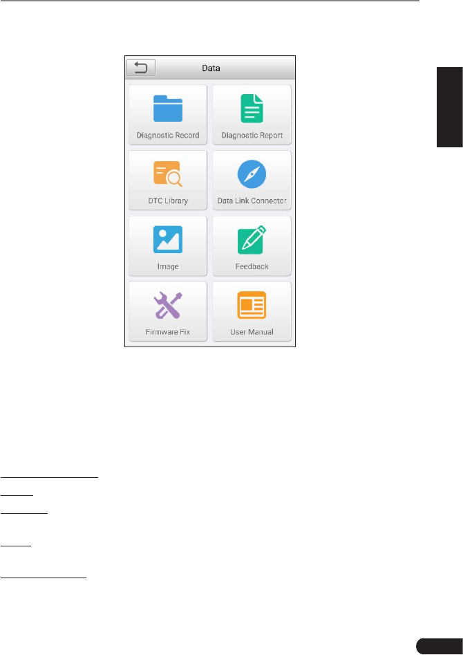
7. Data ........................................................................................................ 29
7.1 Diagnostic Record ....................................................................................... 29
7.2 Diagnostic Report ........................................................................................ 30
7.3 DTC Library ................................................................................................. 30
7.4 DLC(Data Link Connector) Location............................................................ 31
7.5 Image........................................................................................................... 31

v
LAUNCH GEAR SCAN User's Manual
EN
7.6 Feedback ..................................................................................................... 31
7.7 Firmware Fix ................................................................................................ 31
7.8 User Manual ................................................................................................ 31
8. Settings ................................................................................................. 32
8.1 Units of measurement ................................................................................. 32
8.2 Automatic detection on connect................................................................... 32
8.3 Display & Brightness ................................................................................... 32
8.4 Sound .......................................................................................................... 32
8.5 Network ....................................................................................................... 32
8.6 Date/Time .................................................................................................... 32
8.7 Language..................................................................................................... 32
8.8 Email Setup ................................................................................................. 33
8.9 Recovery ..................................................................................................... 33
8.10 Version....................................................................................................... 33
8.11 About .......................................................................................................... 33
9. FAQ ........................................................................................................ 34

1
LAUNCH GEAR SCAN User's Manual
EN
1. Introduction
GEAR SCAN is an evolutionary smart solution for passenger car diagnosis. It
inherits from LAUNCH’s advanced diagnosing technology and is characterized
by covering a wide range of vehicles, featuring powerful functions, and providing
precise test result.
GEAR SCAN has the following functions and advantages:
• Smart(Auto-Detect) Diagnosis: Once GEAR SCAN and the vehicle are
properly connected, the system starts auto-detect process. Once the whole
process is successfully finished, a diagnostic report will be automatically
generated and sent to your email box (if bound).
• Manual Diagnosis: If Auto-Detect failure occurs, manual diagnosis is also
available. Diagnosis functions include: Version Information, Read DTCs,
Clear DTCs and Read Data Stream (supports 3 display modes: Value, Graph
and Merged).
• OBDII/EOBD Diagnosis: 10 modes of OBD II test are supported, including
EVAP, O2 Sensor, I/M Readiness, MIL Status, VIN Info, and On-board
monitors testing etc.
• Remote Diagnosis (optional): This option aims to help repair shops or
technicians launch instant messaging and remote diagnosis, making the
repair job getting xed faster.
• Reset: Frequently used maintenance and reset items including Oil lamp reset,
DPF regeneration, Electronic parking brake reset, Steering angle calibration,
IMMO service, Battery maintenance system reset, ABS bleeding can be done.
• One-click Update: Let you update your diagnostic software and APK online.
• Diagnostic History: This function provides a quick access to the tested
vehicles and users can choose to view the test report or resume from the last
operation, without the necessity of starting from scratch.
• Diagnostic Feedback: Use this option to submit the vehicle issue to us for
analysis and troubleshooting.
• DTC Library: Allows you to retrieve the definition of the diagnostic trouble
code from the abundant DTC database.
• Displays battery real-time voltage once properly connected to the vehicle.
• Features screenshot capture. Screenshots and reports sharing are supported.
• Touch & Keypad input are supported. Quick Dial buttons enables you to easily
access the corresponding functions.
Moreover, GEAR SCAN also features a GEAR+ future community platform
for promotion and advertisement pushing, software subscription and other
information releasing.

2
LAUNCH GEAR SCAN User's Manual
2. General Information
2.1 On-Board Diagnostics (OBD) II
The first generation of On-Board Diagnostics (OBD I) was developed by the
California Air Resources Board (ARB) and implemented in 1988 to monitor some
of the emission control components on vehicles. As technology evolved and the
desire to improve the On-Board Diagnostic system increased, a new generation
of On-Board Diagnostic system was developed. This second generation of On-
Board Diagnostic regulations is called “OBD II”.
The OBD II system is designed to monitor emission control systems and key
engine components by performing either continuous or periodic tests of specic
components and vehicle conditions. When a problem is detected, the OBD II
system turns on a warning lamp (MIL) on the vehicle instrument panel to alert
the driver typically by the phrase of “Check Engine” or “Service Engine Soon”.
The system will also store important information about the detected malfunction
so that a technician can accurately nd and x the problem. Here below follow
three pieces of such valuable information:
1) Whether the Malfunction Indicator Light (MIL) is commanded ‘on’ or ‘off’;
2) Which, if any, Diagnostic Trouble Codes (DTCs) are stored;
3) Readiness Monitor status.
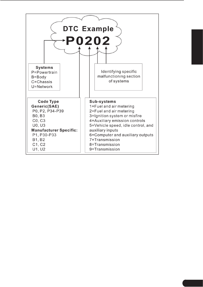
2.2 Diagnostic Trouble Codes (DTCs)
OBD II Diagnostic Trouble Codes are codes that are stored by the on-board
computer diagnostic system in response to a problem found in the vehicle. These
codes identify a particular problem area and are intended to provide you with a
guide as to where a fault might be occurring within a vehicle. OBD II Diagnostic
Trouble Codes consist of a five-digit alphanumeric code. The first character,
a letter, identifies which control system sets the code. The second character,
a number, 0-3; other three characters, a hex character, 0-9 or A-F provide
additional information on where the DTC originated and the operating conditions
that caused it to set. Here below is an example to illustrate the structure of the
digits:
3
LAUNCH GEAR SCAN User's Manual
EN
Figure 2-1
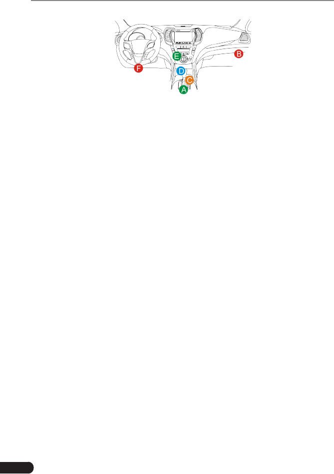
2.3 Location of the Data Link Connector (DLC)
The DLC (Data Link Connector or Diagnostic Link Connector) is typically a 16-
pin connector where diagnostic code readers interface with the vehicle’s on-
board computer. The DLC is usually located 12 inches from the center of the
instrument panel (dash), under or around the driver’s side for most vehicles. If
Data Link Connector is not located under dashboard, a label should be there
telling location. For some Asian and European vehicles, the DLC is located
behind the ashtray and the ashtray must be removed to access the connector. If
the DLC cannot be found, refer to the vehicle’s service manual for the location.
4
LAUNCH GEAR SCAN User's Manual
Figure 2-2
2.4 OBD II Readiness Monitors
An important part of a vehicle’s OBD II system is the Readiness Monitors, which
are indicators used to find out if all of the emissions components have been
evaluated by the OBD II system. They are running periodic tests on specific
systems and components to ensure that they are performing within allowable
limits.
Currently, there are eleven OBD II Readiness Monitors (or I/M Monitors) dened
by the U.S. Environmental Protection Agency (EPA). Not all monitors are
supported in every vehicles and the exact number of monitors in any vehicle
depends on the motor vehicle manufacturer’s emissions control strategy.
Continuous Monitors -- Some of the vehicle components or systems are
continuously tested by the vehicle’s OBD II system, while others are tested
only under specific vehicle operating conditions. The continuously monitored
components listed below are always ready:
1. Misre
2. Fuel System
3. Comprehensive Components (CCM)
Once the vehicle is running, the OBD II system is continuously checking the
above components, monitoring key engine sensors, watching for engine misre,
and monitoring fuel demands.
Non-Continuous Monitors -- Unlike the continuous monitors, many emissions
and engine system components require the vehicle to be operated under
specic conditions before the monitor is ready. These monitors are termed non-
continuous monitors and are listed below:
1) EGR System
2) O2 Sensors
3) Catalyst
4) Evaporative System
5) O2 Sensor Heater

5
LAUNCH GEAR SCAN User's Manual
EN
6) Secondary air Injection
7) Heated Catalyst
8) A/C system
2.5 OBD II Monitor Readiness Status
OBD II systems must indicate whether or not the vehicle’s PCM’s monitor
system has completed testing on each component. Components that have been
tested will be reported as “Ready”, or “Complete”, meaning they have been
tested by the OBD II system. The purpose of recording readiness status is to
allow inspectors to determine if the vehicle’s OBD II system has tested all the
components and/or systems.
The Powertrain Control Module (PCM) sets a monitor to “Ready” or “Complete”
after an appropriate drive cycle has been performed. The drive cycle that
enables a monitor and sets readiness codes to “Ready” varies for each
individual monitor. Once a monitor is set as “Ready” or “Complete”, it will remain
in this state. A number of factors, including erasing of Diagnostic Trouble Codes
(DTCs) with a code reader or a disconnected battery, can result in Readiness
Monitors being set to “Not Ready”. Since the three continuous monitors are
constantly evaluating, they will be reported as “Ready” all of the time. If testing
of a particular supported non-continuous monitor has not been completed, the
monitor status will be reported as “Not Complete” or “Not Ready.”
In order for the OBD monitor system to become ready, the vehicle should be
driven under a variety of normal operating conditions. These operating conditions
may include a mix of highway driving and stop and go, city type driving, and at
least one overnight-off period. For specic information on getting your vehicle’s
OBD monitor system ready, please consult your vehicle owner’s manual.
2.6 OBD II Denitions
Powertrain Control Module (PCM) -- OBD II terminology for the on-board
computer that controls engine and drive train.
Malfunction Indicator Light (MIL) -- Malfunction Indicator Light (Service Engine
Soon, Check Engine) is a term used for the light on the instrument panel. It
is to alert the driver and/or the repair technician that there is a problem with
one or more of vehicle’s systems and may cause emissions to exceed federal
standards. If the MIL illuminates with a steady light, it indicates that a problem
has been detected and the vehicle should be serviced as soon as possible.
Under certain conditions, the dashboard light will blink or ash. This indicates a
severe problem and flashing is intended to discourage vehicle operation. The
vehicle onboard diagnostic system cannot turn the MIL off until the necessary
repairs are completed or the condition no longer exists.

6
LAUNCH GEAR SCAN User's Manual
DTC -- Diagnostic Trouble Codes (DTC) that identifies which section of the
emission control system has malfunctioned.
Enabling Criteria -- Also termed Enabling Conditions. They are the vehicle-
specic events or conditions that must occur within the engine before the various
monitors will set, or run. Some monitors require the vehicle to follow a prescribed
“drive cycle” routine as part of the enabling criteria. Drive cycles vary among
vehicles and for each monitor in any particular vehicle. Please refer to the
vehicle’s factory service manual for specic enabling procedures.
OBD II Drive Cycle -- A specific mode of vehicle operation that provides
conditions required to set all the readiness monitors applicable to the vehicle to
the “ready” condition. The purpose of completing an OBD II drive cycle is to force
the vehicle to run its onboard diagnostics. Some form of a drive cycle needs to
be performed after DTCs have been erased from the PCM’s memory or after
the battery has been disconnected. Running through a vehicle’s complete drive
cycle will “set” the readiness monitors so that future faults can be detected. Drive
cycles vary depending on the vehicle and the monitor that needs to be reset. For
vehicle specic drive cycle, consult the service manual.
Freeze Frame Data -- When an emissions related fault occurs, the OBD II
system not only sets a code but also records a snapshot of the vehicle operating
parameters to help in identifying the problem. This set of values is referred to
as Freeze Frame Data and may include important engine parameters such as
engine RPM, vehicle speed, air ow, engine load, fuel pressure, fuel trim value,
engine coolant temperature, ignition timing advance, or closed loop status.
Fuel Trim (FT) - Feedback adjustments to the base fuel schedule. Short-term
fuel trim refers to dynamic or instantaneous adjustments. Long-term fuel trim
refers to much more gradual adjustments to the fuel calibration schedule than
short-term trim adjustments. These long-term adjustments compensate for
vehicle differences and gradual changes that occur over time.
7
LAUNCH GEAR SCAN User's Manual
EN
3. Product Descriptions
3.1 Outline of GEAR SCAN
Figure 3-1
No. Name Descriptions
1LCD Indicates test results.
2I/M A quick dial to Read I/M readiness.
*Note: This funcon only applies to Diagnose.

8
LAUNCH GEAR SCAN User's Manual
3 Auto VIN
Detect
Press it to quickly launch the auto VIN detection
module.
*Note: To detect more and accurate VINs, a stable
network connecon is highly recommened for this
funcon.
4 Update
A quick access to the Update module.
*Note: This funcon requires a stable network
connecon.
5 Return Exit the current program or return to the previous
screen.
6 HOME Press to the home(Job menu) screen.
7
/Move cursor up and down for selection.
/
Move cursor left or right for selection; Or turn
page up and down when more than one page is
displayed.
8OBD-16
connector
To connect to vehicle's DLC (Data Link Connector)
via diagnostic cable.
95V Charging port To connect to external DC power for charging
GEAR SCAN.
10 Power
• In Off mode, press it for about 5 seconds to turn
the handset on.
• In On mode:
• Press it to activate the LCD if the LCD is off.
• Press it to turn off the LCD if the LCD lights
up.
• Press it for 3 seconds to turn it off.
11 OK Conrms a selection (or action) from a menu list.
12 Screenshots
Press it once to capture the current screen. All
screenshots are saved in the “Image” folder of
“Data”.
13 Diagnostic
Reports
A quick dial to the “Diagnostic Reports” module.
Alternatively, it can also be accessed by “Data” ->
“Diagnostic Report”.
9
LAUNCH GEAR SCAN User's Manual
EN
14 Help Provides detailed descriptions/tips for diagnostics.
15 Charging LED Red means Charging and Green means Fully
charged.
3.2 Technical Specications
• Screen: 5” IPS touch screen
• RAM: 1G
• ROM: 8GB
• Battery: 4000mAh rechargeable Li-battery
• OBDII input voltage range: 9~18V
• Touch & Keypad input
• Charging via:
• DC 5V charging cable or
• Diagnostic cable through connection to vehicle’s DLC
• Dimension: 248.7mm x 93.5mm x 36mm
• Net weight: 530g
• Working temperature: -10 to 50°C (14 to 122 F°)
• Storage temperature: -20 to 70°C (-4 to 158 F°)
3.3 Accessories Checklist
For detailed accessory items, please consult from the local agency or check the
packing list supplied with GEAR SCAN together.
1. GEAR SCAN handset
2. OBD II diagnostic cable
3. DC 5V charging cable
4. User manual
5. Padded carrying case
10
LAUNCH GEAR SCAN User's Manual
4. Initial Use
4.1 Charging GEAR SCAN
There are two charging methods available:
Via Charging Cable: Plug one end of the included charging cable into the DC-IN
port of the tool, and the other end to the external DC power.
Via Diagnostic Cable: Insert one end of the diagnostic cable into the DB-15
connector of the tool, and the other end to the vehicle’s DLC.
Once the charging LED illuminates solid green, it indicates that the battery is
fully charged.
4.2 Getting Started
If it is the first time you have used this tool, you need to make some system
settings.
1. Press the [Power] button to power it on.
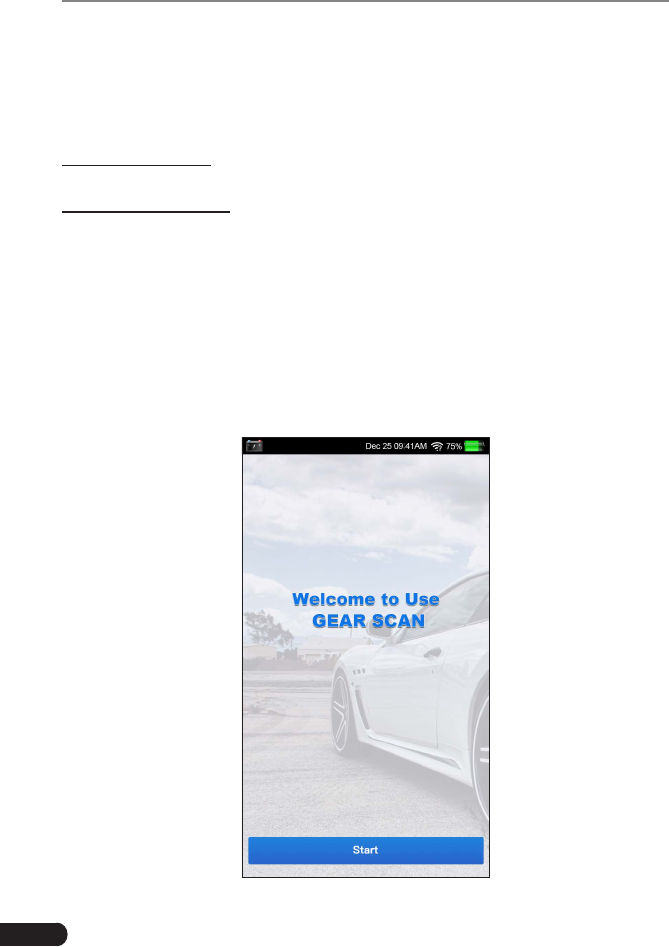
2. The screen displays a welcome page. Tap “Start” to go to next step.
Figure 4-1
11
LAUNCH GEAR SCAN User's Manual
EN
3. Choose the desired system language, and tap “Next”.
4. Choose the desired time zone, and tap “Next” to enter the WLAN setup page.
5. Slide the switch to ON, the system starts searching for all available wireless
LANs. Choose the desired WLAN access point / network,
• If the network you chose is open, you can connect directly;
• If the selected network is encrypted, you have to enter the right security
key (network password).
*Note: If you choose “Ignore” in WLAN setup, it will go into the date seng page. If the
tool has been properly connected to the Internet, the system will automacally obtain
the correct network date and me and navigate to step 6.
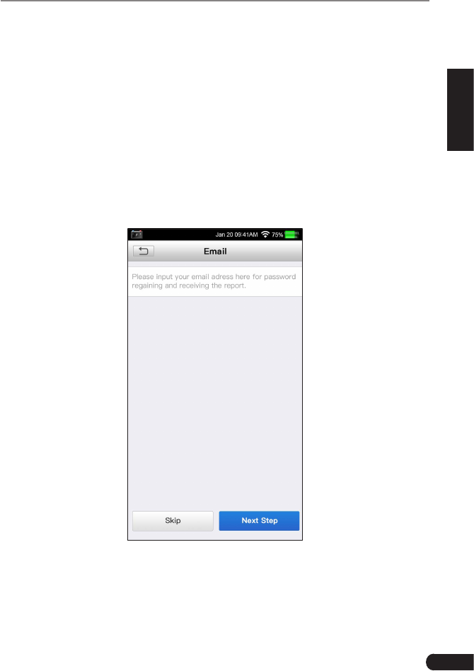
6. After the network connection is done, tap “Next” to congure email address.
Input the email address, and tap “Next” to navigate to the Job menu.
Figure 4-2
*Note: You are strongly recommended to fill in the valid email address. Once you
congured this opon, the system will automacally send the diagnosc report to your
email box every me a complete Auto-Detect process is successfully nished.
12
LAUNCH GEAR SCAN User's Manual
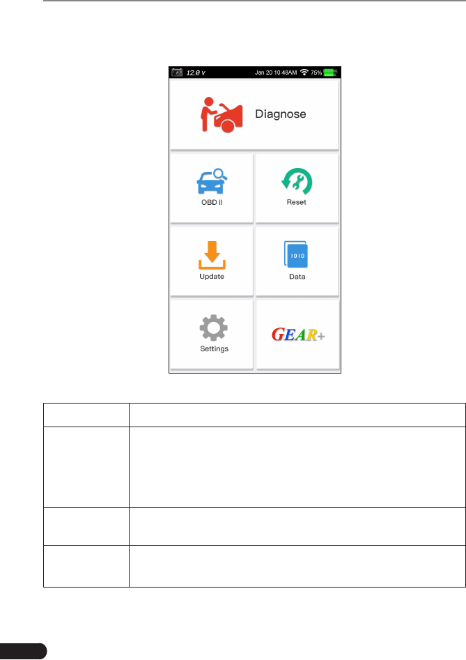
4.3 Job Menu
It mainly includes the following function modules.
Figure 4-3
Diagnose To congures GEAR SCAN to operate as a diagnostic tool.
OBD II
This option presents a quick way to check for DTCs, isolate
the cause of the illuminated Malfunction Indicator Lamp (MIL),
check monitor status prior to emissions certification testing,
verify repairs, and perform a number of other services that are
emission-related.
Reset To perform common repair & maintenance items, including
ABS bleeding, DPF regeneration and oil lamp reset etc.
Update To update vehicle diagnostic software and APK.
*Note: This function requires a stable network connection.

13
LAUNCH GEAR SCAN User's Manual
EN
Data Includes Diagnostic report, Diagnostic record, Feedback and
Image etc.
Settings To make some system settings, including Network setup,
Email and Brightness etc.
GEAR+
(Coming soon)
An add-on module for function extension, including Promotion
message pushing and Software subscription etc.
14
LAUNCH GEAR SCAN User's Manual
5. Diagnose
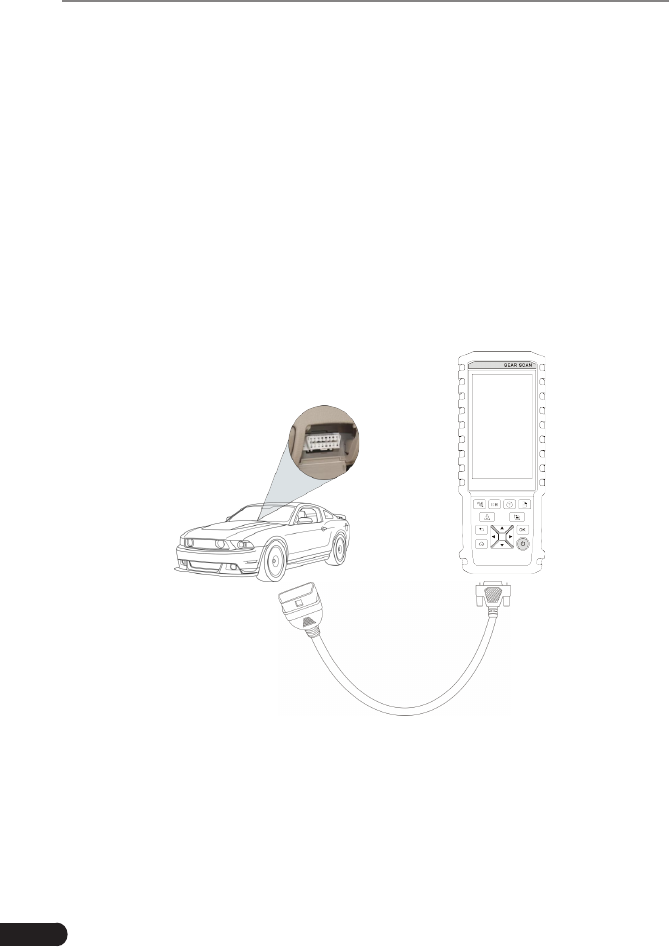
5.1 Connection
1. Turn the ignition off.
2. Locate vehicle’s DLC socket: It provides standard 16 pins and is generally
located on driver’s side, about 12 inches away from the center of dashboard.
See Figure 2-2. If DLC is not equipped under dashboard, a label indicating
its position will be given. In case no DLC is found, please refer to Automobile
Repair Manual.
3. Plug one end of the diagnostic cable into the DB-15 connector of GEAR
SCAN, and tighten the captive screws. Connect the other end to the vehicle’s
DLC.
Diagnostic Cable
GEAR SCAN
Vehicle's DLC
Figure 5-1
5.2 System Diagnosing
This function is specially designed to diagnose electronic control systems of
single vehicle model.
15
LAUNCH GEAR SCAN User's Manual
EN
5.2.1 Smart Diagnosis (Auto-Detect)
After connection, turn the ignition key on and the system enters auto-detect
mode.
*Note: To detect more and accurate VINs, a stable network connection is highly
recommended for this funcon.
*CAUTION: Don’t connect or disconnect any test equipment with ignion on or engine
running.
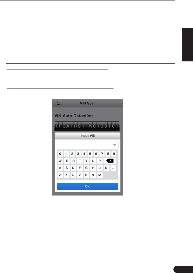
A. Once the system successfully obtains the VIN (Vehicle Identication Number)
information of the currently identified vehicle, it will continue scanning the
vehicle systems. After the scanning is complete, a diagnostic report will be
automatically generated and sent to your email box (if bound).
B. If the tool failed to access the VIN information, the screen will display as
below:
Fig. 5-2
Input the VIN, and tap “OK”, the system will automatically identify the vehicle
model. If the vehicle VIN is successfully decoded, it will perform auto-
diagnosis until a diagnostic report is automatically output. Otherwise it will
enter manual diagnosis mode. For details on manual diagnosis, see Chapter
5.2.2.
*Notes:
• The most recognizable location for this number is in the top left corner on the
vehicle’s dashboard. Other locations include the driver’s door or post, and the
16
LAUNCH GEAR SCAN User's Manual
rewall under the hood.
• In general, vehicle identification numbers are standardized - all contain 17
characters. VIN characters may be capital letters A through Z and numbers
1 through 0; however, the letters I, O and Q are never used in order to avoid
mistakes of misreading. No signs or spaces are allowed in the VIN.
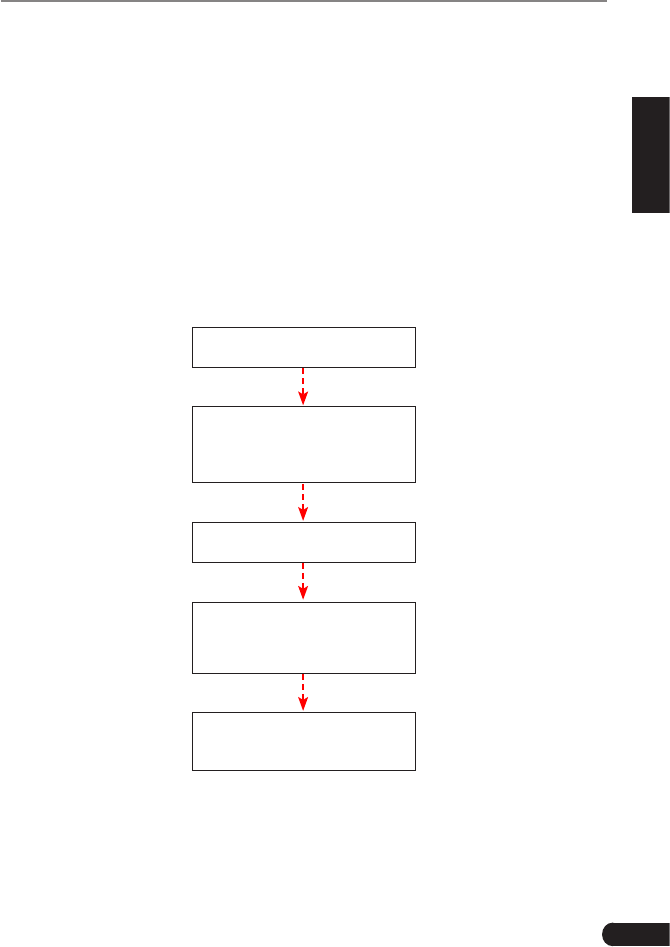
5.2.2 Manual Diagnosis
If the tool can not obtain the VIN information, you can also perform vehicle
diagnosis manually. In this mode, you need to execute the menu-driven
command and then follow the on-screen instruction to proceed.
*Notes:
• Before diagnosing, please make sure the diagnosc program corresponding to certain
vehicle model has been installed on your GEAR SCAN.
• For vehicles manufactured by different vendors, it is possible that it has different
diagnosc menus. For details, please follow the instrucons on the screen to proceed.
Refer to the owchart illustrated as below to diagnose a vehicle manually:
Select “Diagnose”
Automatic
(Note: This mode allows
your tool to scan the vehicle
test system automatically)
Manual Select
(Note: In this case, you need to choose the
desired system manually. Just follow the
on-screen instructions to proceed.)
Select test system
Select test function
Select Vehicle Model
(Note: For different vehicles,
vehicle make selection may
differ. Generally, we can
choose a vehicle via make
year. But for BENZ, we need
to choose it via chassis.)
Select Vehicle
Manufacturer
Read version
information
Read fault code
Clear fault code
Read data stream
17
LAUNCH GEAR SCAN User's Manual
EN
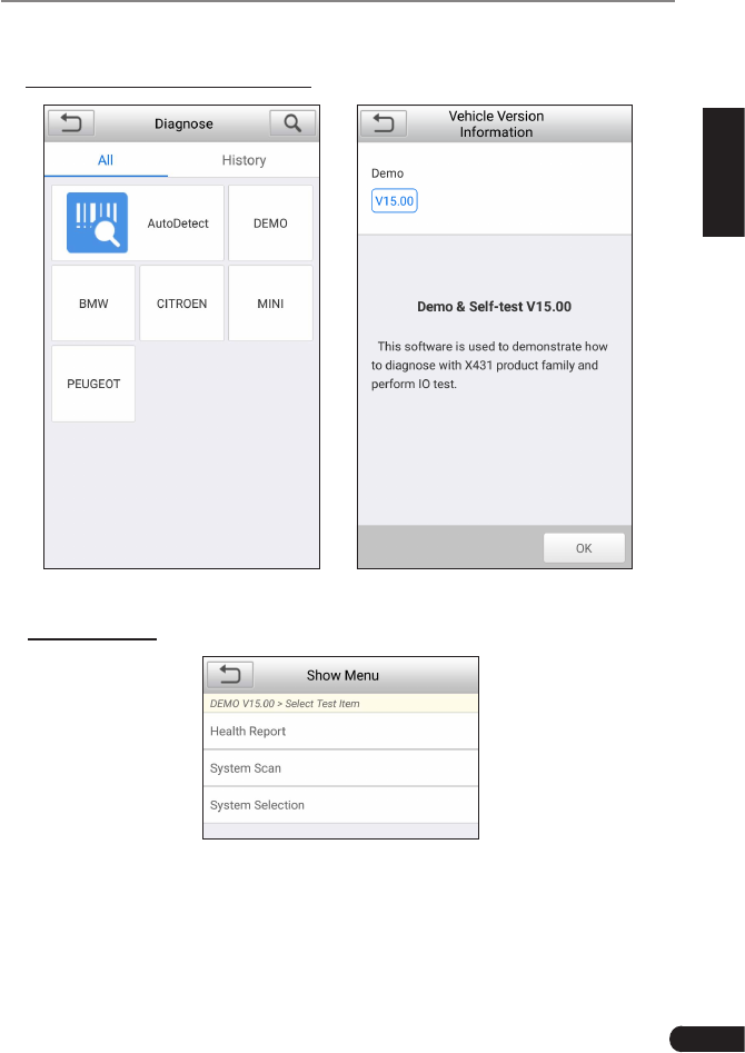
Take Demo as an example to demonstrate how to diagnose a vehicle.
1). Select diagnostic software version: Tap the “DEMO” to go to Step 2.
Fig. 5-3 Fig. 5-4
2). Select test item: Select the desired test item to proceed.
Fig. 5-5
5.2.2.1 Health Report (Quick Test)
This function varies from vehicle to vehicle. It enables you to quickly access all
the electronic control units of the vehicle and generate a detailed report about
vehicle health.
18
LAUNCH GEAR SCAN User's Manual
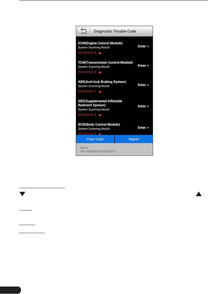
Tap “Health Report”, the system starts scanning the ECUs. Once the scanning is
complete, a screen similar to the following appears:
Fig. 5-6
In above gure, the tested system with fault code appears in red and the system
with OK displays in white (normally).
On-screen Buttons:
: Tap to display the details of DTCs existing in the current system. Tap to
hide it.
Enter: Tap to select other test functions. For detailed operations, refer to Chapter
5.2.2.3 “System Selection”.
Report: Tap to save the diagnostic result as a report.
Clear DTC: Tap to clear the existing diagnostic trouble codes.
5.2.2.2 System Scan
This option allows you to quickly scan which systems are installed on the vehicle.
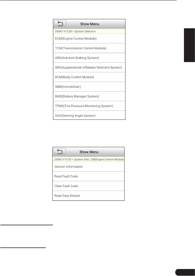
5.2.2.3 System Selection
This option allows you manually select the test system and function step by step.
19
LAUNCH GEAR SCAN User's Manual
EN
In Fig. 5-5, tap “System Selection”, the screen displays as follows:
Fig. 5-7
Tap the desired system (take “ECM” for example) to jump to the test function
page.
Fig. 5-8
*Note: Dierent vehicle has dierent diagnosc menus.
A. Version Information
This function is used to read the version information of system mode, vehicle
VIN, software and ECU.
B. Read Fault Code
This function displays the detailed information of DTC records retrieved from the
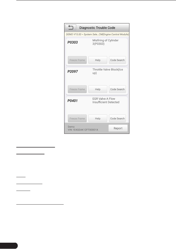
20
LAUNCH GEAR SCAN User's Manual
vehicle’s control system.
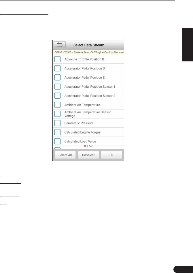
In Fig. 5-8, tap “Read DTC”, the screen will display the diagnostic result.
Fig. 5-9
On-screen Buttons:
Freeze Frame: When an emission-related fault occurs, certain vehicle conditions
are recorded by the on-board computer. This information is referred to as freeze
frame data. Freeze frame data includes a snapshot of critical parameter values
at the time the DTC is set.
Help: Tap to view the help information.
Code Search: Tap it to search for more information about the current DTC online.
Report: To save the current data in text format. All diagnostic reports can be
accessed from “Data” -> “Diagnostic Report”.
C. Clear Fault Memory
After reading the retrieved codes from the vehicle and certain repairs have been
carried out, you can use this function to erase the codes from the vehicle. Before
performing this function, please be sure the vehicle’s ignition key is in the ON
position with the engine off.
*Note: The trouble code will not disappear unl the trouble was completely cleared.
21
LAUNCH GEAR SCAN User's Manual
EN
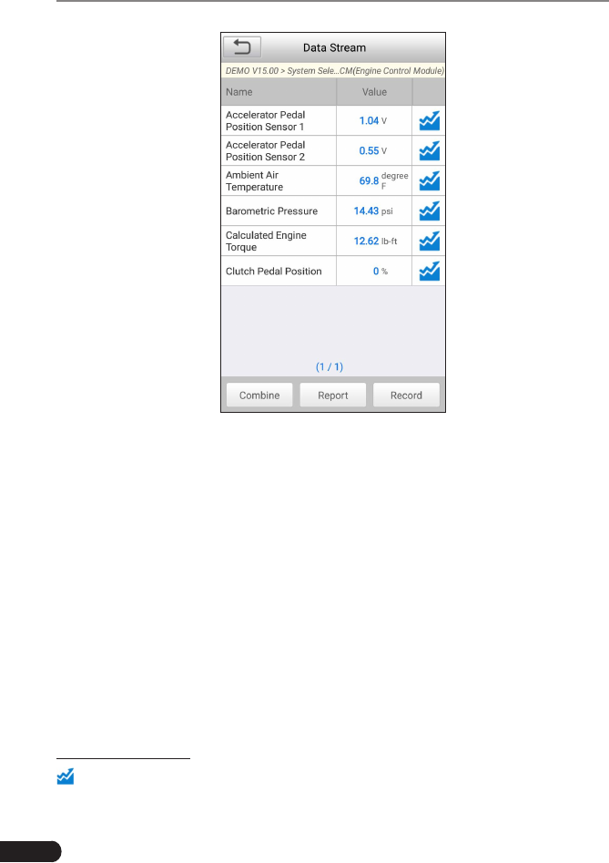
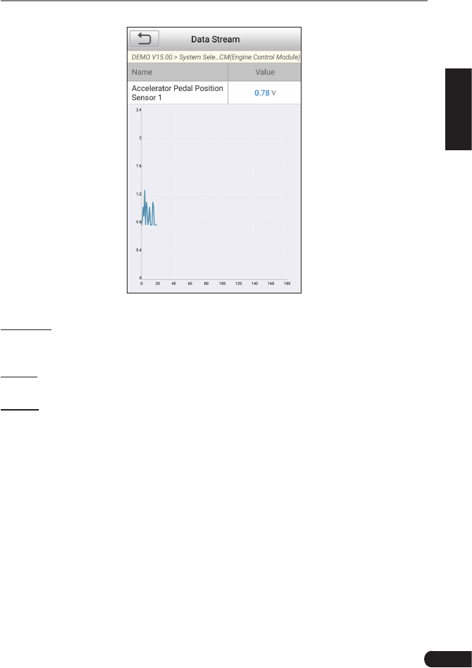
D. Read Data Stream
This option retrieves and displays live data and parameters from the vehicle’s
ECU.
In Fig. 5-8, tap “Read Data Stream”, the system will display data stream items.
Fig. 5-10
On-screen Buttons:
Select All: Tap it to select all items of the current page. To select certain data
stream item, just check the box before the item name.
Unselect: Tap it to deselect all data stream items.
OK: Tap it to conrm and jump to the next step.
After selecting the desired items, tap “OK” to enter the data stream reading
page.
22
LAUNCH GEAR SCAN User's Manual
Fig. 5-11
*Notes:
1. If the value of the data stream item is out of the range of the standard (reference)
value, the whole line will display in red. If it complies with the reference value, it
displays in blue (normal mode).
2. The indicator 1/X shown on the boom of the screen stands for the current page/
total page number. Swipe the screen from the right/left to advance/return to the
next/previous page.
There are 3 types of display modes available for data viewing, allowing you to
view various types of parameters in the most suitable way.
• Value – this is the default mode which displays the parameters in texts and
shows in list format.
• Graph – displays the parameters in waveform graphs.
• Combine – this option is mostly used in graph merge status for data
comparison. In this case, different items are marked in different colors.
On-screen Buttons:
: Tap it to view the waveform graph of the current data stream item.
23
LAUNCH GEAR SCAN User's Manual
EN
Fig. 5-12
Combine: Tap it, a pull-down list of the data stream items appears on the
screen. Select the necessary items and the screen will display the waveforms
corresponding to these items immediately.
Report: To save the current data as a diagnostic report. All diagnostic reports
can be accessed from “Data” -> “Diagnostic Report”.
Record: Tap to start recording diagnostic data for future playback and analysis.
The saved le follows the naming rule: It begins with vehicle type, and then the
record starting time and ends with .x431 (To differentiate between les, please
congure the accurate system time). All diagnostic records can be replayed from
“Data” -> “Diagnostic Record”.
5.3 OBDII Diagnosis
This option presents a quick way to check for DTCs, isolate the cause of the
illuminated Malfunction Indicator Lamp (MIL), check monitor status prior to
emissions certification testing, verify repairs, and perform a number of other
services that are emission-related.
On the Job menu, press [OBD II] to enter system, the screen will automatically
jump to gure 5-13:
24
LAUNCH GEAR SCAN User's Manual
Figure 5-13 Figure 5-14
Tap [OK], a screen similar to Figure 5-14 will appear.
It mainly includes the following functions:
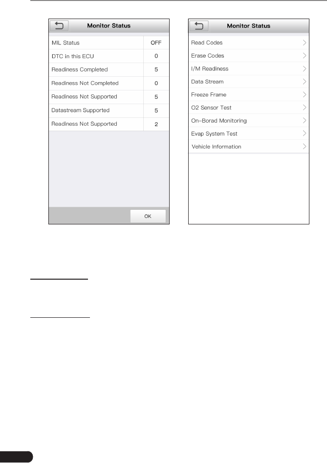
1. Read Codes
This option is used to identify which section of the emission control system has
malfunctioned.
2. Erase Codes
After reading the retrieved codes from the vehicle and certain repairs have been
carried out, you can use this function to erase the codes from the vehicle. Before
performing this function, please be sure the vehicle’s ignition key is in the ON
position with the engine off.
*Notes:
• Before performing this funcon, make sure to retrieve and record the trouble codes.
• After clearing, you should retrieve trouble codes once more or turn ignition on
and retrieve codes again. If there are sll some trouble codes in the system, please
troubleshoot the code using a factory diagnosis guide, then clear the code and
recheck.

25
LAUNCH GEAR SCAN User's Manual
EN
3. I/M Readiness
I/M refers to Inspection and Maintenance that is legislated by the Government
to meet federal clean-air standards. I/M Readiness indicates whether or not the
various emissions-related systems on the vehicle are operating properly and are
ready for Inspection and Maintenance testing.
The purpose of the I/M Readiness Monitor Status is to indicate which of the
vehicle’s Monitors have run and completed their diagnosis and testing (as
described in Chapter 2.5), and which ones have not yet run and completed
testing and diagnosis of their designated sections of the vehicle’s emissions
system.
The I/M Readiness Monitor Status function also can be used (after repair of
a fault has been performed) to confirm that the repair has been performed
correctly, and/or to check for Monitor Run Status.
4. Data Stream
This option retrieves and displays live data and parameters from the vehicle’s
ECU.
5. View Freeze Frame
When an emission-related fault occurs, certain vehicle conditions are recorded
by the on-board computer. This information is referred to as freeze frame data.
Freeze Data is a snapshot of the operating conditions at the time of an emission-
related fault.
*Note: If DTCs were erased, Freeze Data may not be stored in vehicle memory
depending on vehicle.
6. O2 sensor test
The results of O2 sensor test are not live values but instead the results of the
ECU’s last O2 sensor test. For live O2 sensor readings, refer to any of the live
sensor screens such as Graph Screen.
Not all test values are applicable to all vehicles. Therefore, the list generated
will vary depending on vehicle. In addition, not all vehicles support the Oxygen
Sensors screen.
7. On-board monitor test
This function can be utilized to read the results of on-board diagnostic monitoring
tests for specic components/systems.
8. EVAP System Test
The EVAP test function lets you initiate a leak test for the vehicle’s EVAP system.
The GEAR SCAN does not perform the leak test, but signals to vehicle’s on-
26
LAUNCH GEAR SCAN User's Manual
board computer to initiate the test. Before using the system test function, refer
to the vehicle’s service repair manual to determine the procedures necessary to
stop the test.
9. Vehicle Info
This option displays the vehicle information, such as VIN (Vehicle Identication
Number), CID (Calibration ID) and CVN (Calibration Verication Number).
5.4 History
Generally once a vehicle diagnosis is performed, GEAR SCAN will record the
every details of diagnostic session. The History function provides direct access
to the previously tested vehicles and users can resume from the last operation,
without the necessity of starting from scratch.
Tap “History” on the Manual Diagnosis main menu screen, all diagnostic records
will be listed on the screen in date sequence.
Fig. 5-15
• Tap certain vehicle model to view the details of the last diagnostic report.
• To delete certain diagnostic history, select it and then tap “Delete”. To delete
all historical records, tap “Select All” and then tap “Delete”.
27
LAUNCH GEAR SCAN User's Manual
EN
• Tap “Quick access” to directly navigate to the function selection page of last
diagnostic operation. Choose the desired option to proceed.
5.5 Resetting
In addition to amazing & powerful diagnostic function, GEAR SCAN also features
Oil / Service lamp reset etc.
There are two methods to reset service lamp: Manual reset or Auto reset. Auto
reset follows the principle of sending command from GEAR SCAN to vehicle’s
ECU to do resetting. While using manual reset, users just follow the on-screen
instructions to select appropriate execution options, enter correct data or values,
and perform necessary actions, the system will guide you through the complete
performance for various service operations.
Follow the owchart shown as below to perform resetting.
Select "Reset"
Choose the desired service
function (e.g. oil lamp reset
etc.)
Select the desired car brand
Select the reset mode (The
available mode varies from
vehicle to vehicle)
Follow the on-screen
instructions to proceed

28
LAUNCH GEAR SCAN User's Manual
6. Update
If some new software or APK can be updated, a numeric indicator will display on
the “Upgrade” module on the Job menu. In this case, you may use this option to
keep it synchronized with the latest version.
*Notes:
• To enjoy more funcons and beer service, you are strongly suggested to update it
on regular basis.
• This funcon requires a stable network connecon.
Tap “Upgrade” on the Job menu to enter the update center.
By default, all diagnostic software is selected.
To deselect certain software, tap “Unselect”, and then check the box next to
vehicle model.
Tap “Update” to start downloading. It may take several minutes to nish it, please
be patient to wait. To pause downloading, tap “Stop”. To resume it, tap “Continue”.
If network connection failure occurs, tap “Retry” to try again.
Once download is nished, the software packages will be installed automatically.
29
LAUNCH GEAR SCAN User's Manual
EN
7. Data
Fig. 7-1
7.1 Diagnostic Record
If user records the running parameters or waveform graphs while reading data
stream, it will be saved as diagnostic records and appear under this tab.
Tap “Diagnostic Record” to enter and select the desired data stream items and
tap “OK” to jump to the playback page.
On-screen Buttons:
Graph – displays the parameters in waveform graphs.
Combine – this option is mostly used in graph merge status for data comparison.
In this case, different items are marked in different colors.
Value – this is the default mode which displays the parameters in texts and
shows in list format.
Frame Playback – plays back the recorded data stream items frame by frame.
Once it is in frame playback mode, this button changes into “Auto Playback”.
30
LAUNCH GEAR SCAN User's Manual
7.2 Diagnostic Report
This module stores all diagnostic reports generated in process of vehicle
diagnosis.
All the diagnostic reports are sorted by Date and Make. If there are too many
reports stored, tap (Search) to lter and quickly locate it.
• To select certain report, just check the box at the right lower corner of the
report. To select all reports, tap “Select All”. To deselect all, tap “Unselect”.
• Tap it to view its details.
• Select the desired report and then tap “Delete” to delete it.
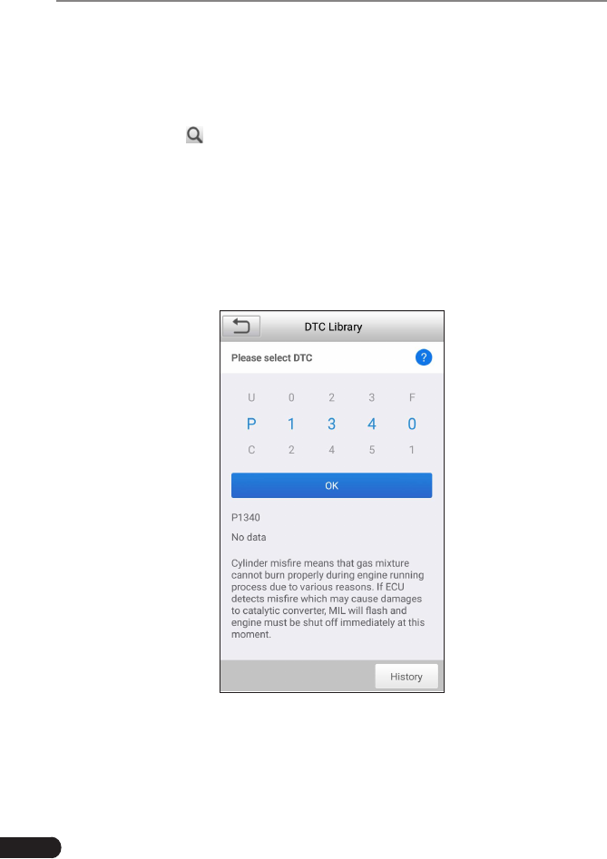
7.3 DTC Library
This option helps you to nd the location of the vehicle’s DLC.
Fig. 7-2
Swipe the screen upwards/downwards to alter the value, then press [OK] button,
the screen will display denition of the DTC.

31
LAUNCH GEAR SCAN User's Manual
EN
7.4 DLC(Data Link Connector) Location
This option helps you to nd the location of the vehicle’s DLC.
7.5 Image
This option enables you to manage the screenshots.
7.6 Feedback
This item allows you to feedback your diagnostic problems to us for analysis and
troubleshooting.
Tap “Feedback”, the following 3 options will be displayed on the left column of
the screen.
A. Feedback
Tap a tested vehicle model to enter the feedback screen.
1) Tap “Choose File” to open the target folder and choose the desired diagnostic
logs.
2) Choose the failure type and ll in the detailed failure description in the blank
text box and telephone or email address. After inputting, tap “Submit Result”
to send it to us.
B. History
Tap it to view all diagnostic feedback records. Different process states are
marked with different colors.
C. Ofine list
Tap it to display all diagnostic feedback logs which have not been submitted
successfully due to network failure. Once the handset gets a stable network
signal, it will be uploaded to the remote server automatically.
7.7 Firmware Fix
Use this item to upgrade and x diagnostic rmware. During xing, please do not
cut power or switch to other interfaces.
7.8 User Manual
Provides a detailed description on how to operate the GEAR SCAN. Before
operating the handset, please carefully read it.

32
LAUNCH GEAR SCAN User's Manual
8. Settings
8.1 Units of measurement
It is designed to set the measurement unit. Metric System and English System
are available.
8.2 Automatic detection on connect
This option enables you to determine whether to start an automatic VIN detection
once GEAR SCAN is properly connected to the vehicle’s DLC.
8.3 Display & Brightness
This item allows you to set the standby time and screen brightness.
*Tips: Reducing the brightness of the screen is helpful to conserve the power of the
handset.
8.4 Sound
This option lets you adjust the volume and other sound settings.
8.5 Network
*Note: Once WLAN is set as ON, GEAR SCAN will consume more power. While it keeps
unused, please set it o to save power. While WLAN keeps unused, please turn it o to
conserve baery power.
GEAR SCAN has built-in WLAN module that can be used to get online. Once
you’re online, you can register your tool, update diagnostic software & APK,
send email on your network.
Slide the switch to ON, the system starts searching for all available wireless
LANs. Choose the desired WLAN access point / network to connect.
8.6 Date/Time
This option allows you to set the system date & time.
*Note: Since all diagnostic reports are sorted by Make and Date. To differentiate
between les, please congure the accurate system me.
8.7 Language
GEAR SCAN supports multiple languages. You can use this option to change
the target language.

33
LAUNCH GEAR SCAN User's Manual
EN
8.8 Email Setup
This option is used to set up the default email address for automatically receiving
the diagnostic reports.
8.9 Recovery
Use this item to reset this tool to the default factory setting.
*Warning: Reseng may cause data loss. Before doing so, please be careful to perform
this operaon.
8.10 Version
BOOT, Download, App and System version are included.
8.11 About
This option displays the hardware configuration information of the tool and
license agreement.

34
LAUNCH GEAR SCAN User's Manual
9. FAQ
Here we list some frequently asked questions and answers related to GEAR
SCAN.
1 System halts when reading data stream. What is the reason?
It may be caused by a slackened connector. Please turn off the GEAR SCAN,
rmly connect the connector, and switch it on again.
2 Screen of main unit ashes at engine ignition start.
Caused by electromagnetic disturbing, and this is normal phenomenon.
3 There is no response when communicating with on-board computer.
Please confirm the proper voltage of power supply and check if the throttle
has been closed, the transmission is in the neutral position, and the water is in
proper temperature.
4 What to do if the system fails to start auto VIN detection?
Please check the following possible reasons:
• Whether GEAR SCAN is properly connected to the vehicle’s DLC.
• Whether the “Automatic detection on Connect” switch is OFF. If yes, slide it to
ON.
5 Why are there so many fault codes?
Usually, it’s caused by poor connection or fault circuit grounding.

35
LAUNCH GEAR SCAN User's Manual
EN
Warranty
THIS WARRANTY IS EXPRESSLY LIMITED TO PERSONS WHO PURCHASE
LAUNCH PRODUCTS FOR PURPOSES OF RESALE OR USE IN THE
ORDINARY COURSE OF THE BUYER’S BUSINESS.
LAUNCH electronic product is warranted against defects in materials and
workmanship for one year (12 months) from date of delivery to the user.
This warranty does not cover any part that has been abused, altered, used for a
purpose other than for which it was intended, or used in a manner inconsistent
with instructions regarding use. The exclusive remedy for any automotive meter
found to be defective is repair or replacement, and LAUNCH shall not be liable
for any consequential or incidental damages.
Final determination of defects shall be made by LAUNCH in accordance with
procedures established by LAUNCH. No agent, employee, or representative of
LAUNCH has any authority to bind LAUNCH to any afrmation, representation,
or warranty concerning LAUNCH automotive meters, except as stated herein.
Order Information
Replaceable and optional parts can be ordered directly from your LAUNCH
authorized tool supplier. Your order should include the following information:
1. Quantity
2. Part number
3. Item description
Customer Service
If you have any questions on the operation of the unit, please contact local
dealer, or contact LAUNCH Tech(USA), Inc.:
Statement: LAUNCH reserves the rights to make any change to this manual without
notice. We have tried our best to make the descriptions and illustrations in the manual as
accurate as possible, and defects are inevitable, if you have any question, please contact
local dealer or LAUNCH Tech(USA), Inc., LAUNCH does not bear any responsibility
arising from misunderstandings.
LAUNCH Tech(USA) Product Support
Phone: 877-528-6249 xt: 4
Fax: 562-463-1590
1820 S. Milliken Ave. Ontario, CA 91761
Monday - Friday 5 am - 5 pm PST
Service & Repair
Phone: 877-528-6249 xt: 5
Monday - Friday 8 am - 5 pm PST
Please visit our public form @
http://launch.activeboard.com