Launch Tech M431PAD Automotive Diagnostic Computer User Manual Manual
Launch Tech Co., Ltd. Automotive Diagnostic Computer Manual
UserManual.wiki
>
Launch Tech
>
M431PAD User Manual
>
Manual
Contents
1.
Manual
2.
Addendum
Manual
Navigation menu
Upload a User Manual
Namespaces
Wiki Guide
HTML
PDF
Info
Views
User Manual
Discussion / Help
Navigation
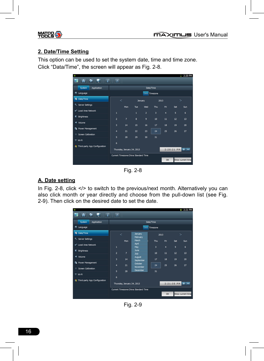
![15 MAXIMUS User's Manual2.4.3 SettingsIt includes system settings and application setting. Language setting, Date/Time, Server Settings, Local Area Network, Brightness, Volume, Power Management, Screen Calibration, Wi-Fi and Third-party App Configuration are available in system setting, while application settings provide some settings related to applications. In main menu, click [ Settings] to enter setting interface, similar to Fig. 2-7.Fig. 2-71. Language settingThis items enables you to change the system language. Due to continuous upgrade, Language interface may vary with different software versions (Fig 2-7 is provided for reference and demo purpose). In Fig. 2-7, click on your preferred language, the system will prompt you that language has been changed, please close the application and then restart it.](https://usermanual.wiki/Launch-Tech/M431PAD.Manual/User-Guide-2014101-Page-22.png)
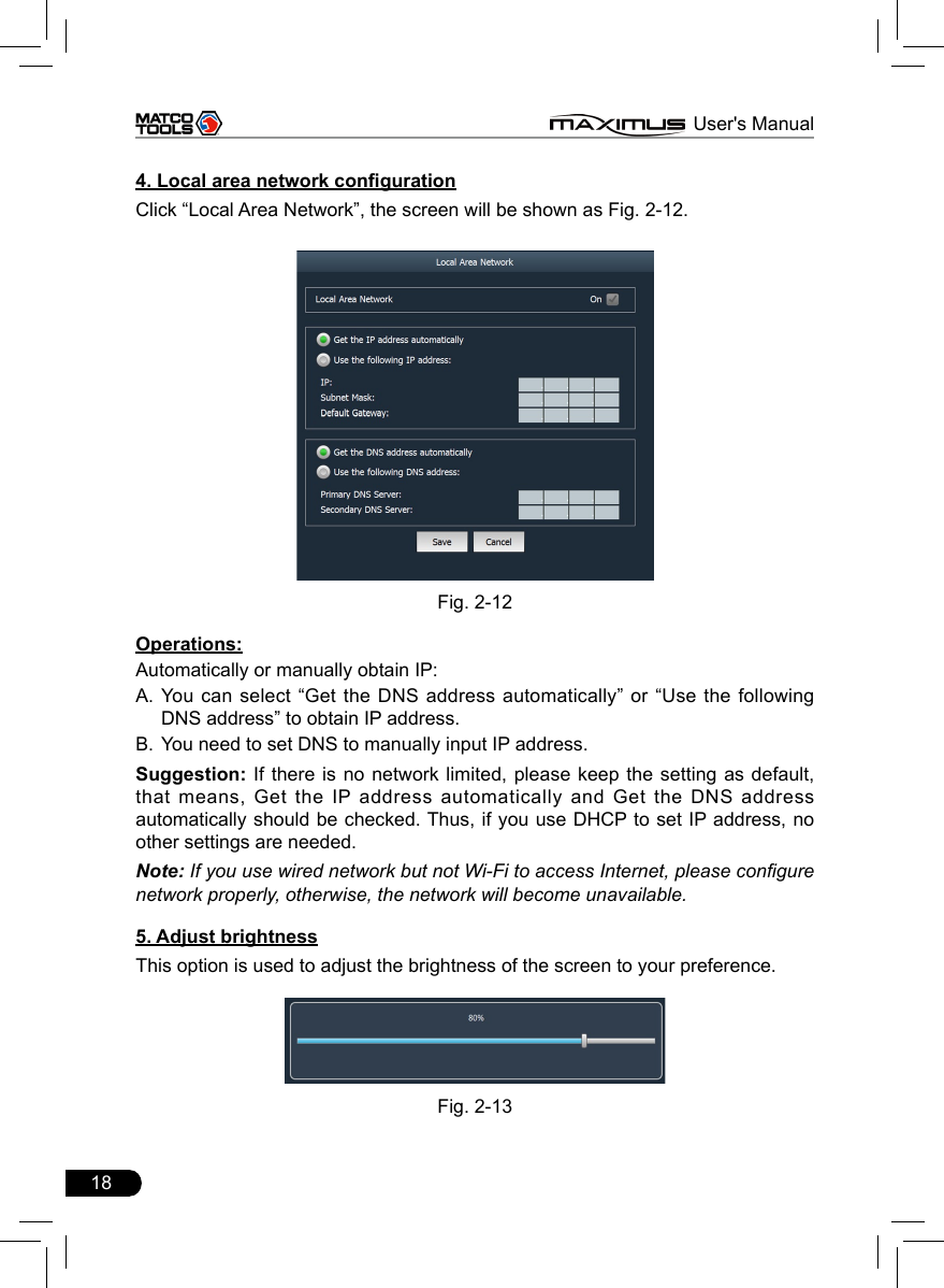
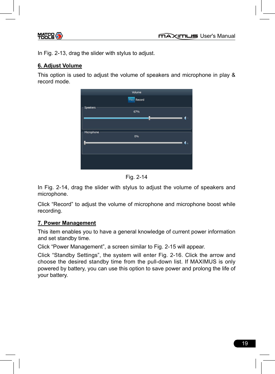
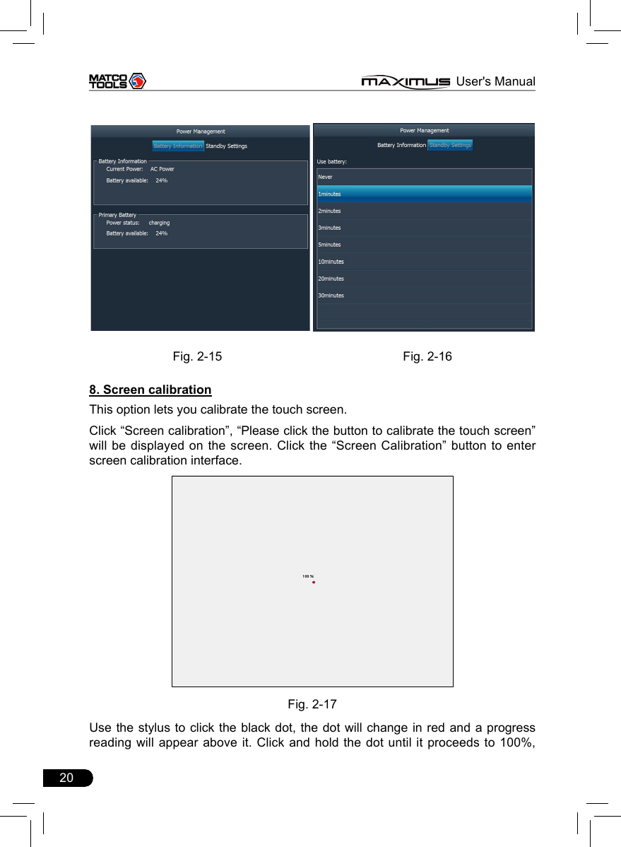
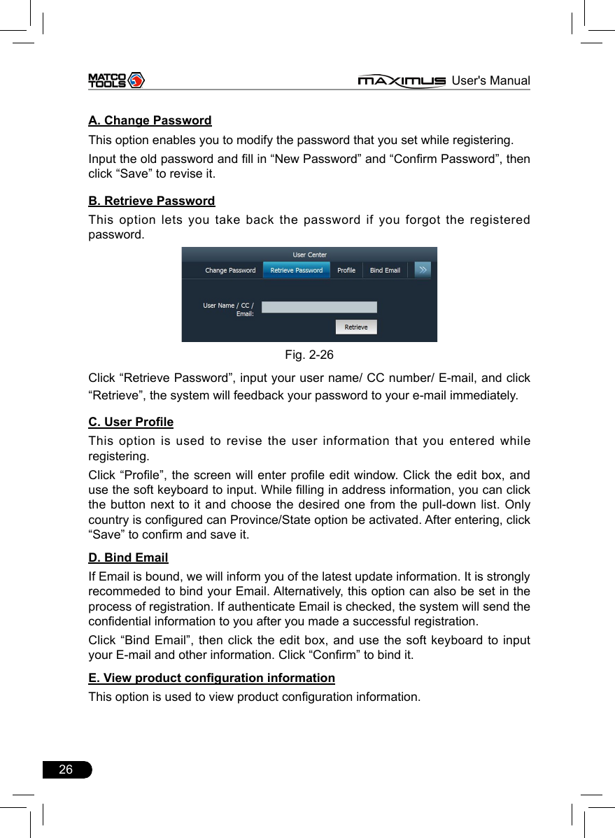
![17 MAXIMUS User's ManualB. Time settingClick on the time display area, the cursor will blink, click the +/- button next to it to adjust it.Click [Show current time] to display the current time.C. Time zone settingClick [Timezone] in Fig. 2-8, a screen similar to 2-10 will appear.Fig. 2-10Click the desired time zone, then click [Date] to switch to date setting screen, the time zone you have set will be displayed on the bottom of the screen and the system time varies with the time zone.3. Server settingThis option provide two server domains for your selection. Users can choose the different domain according to your actual network status.Fig. 2-11](https://usermanual.wiki/Launch-Tech/M431PAD.Manual/User-Guide-2014101-Page-24.png)
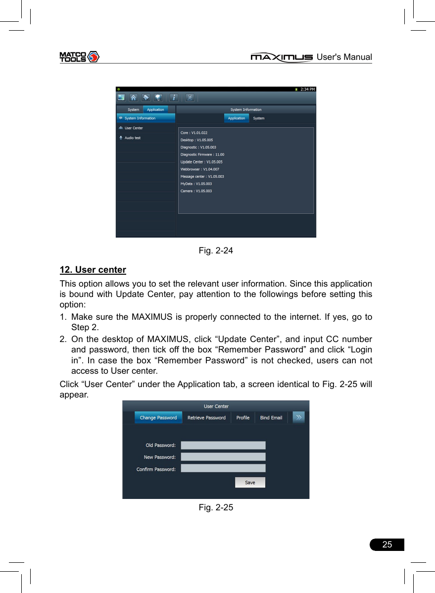
![24 MAXIMUS User's Manualbe displayed on the right window. See Fig. 2-23. If no third-party softwares are installed under Windows 7 operating system, the screen will appear blank.Fig. 2-23Check the desired box before the software name, then click “Save” to save your conguration. The selected items will appear on the main menu of the diagnosis module. Once the installed softwares are shown out of the main menu, another icon will be appended next to the current one. Click the second to turn to next page to browse the hidden items.To remove it, just uncheck the box and click “Save”. To uninstall the software, you need to click to return to Windows 7 operating system and then enter the relative function in “Control Panel” to execute it. 11. System informationThis option enables you to view the relevant system information.Click “System Information” under the Application tab, a dialog box prompting “Please click the refresh button to get the system information” will pop up, click [Refresh], a screen identical to Fig. 2-24 will appear.](https://usermanual.wiki/Launch-Tech/M431PAD.Manual/User-Guide-2014101-Page-31.png)
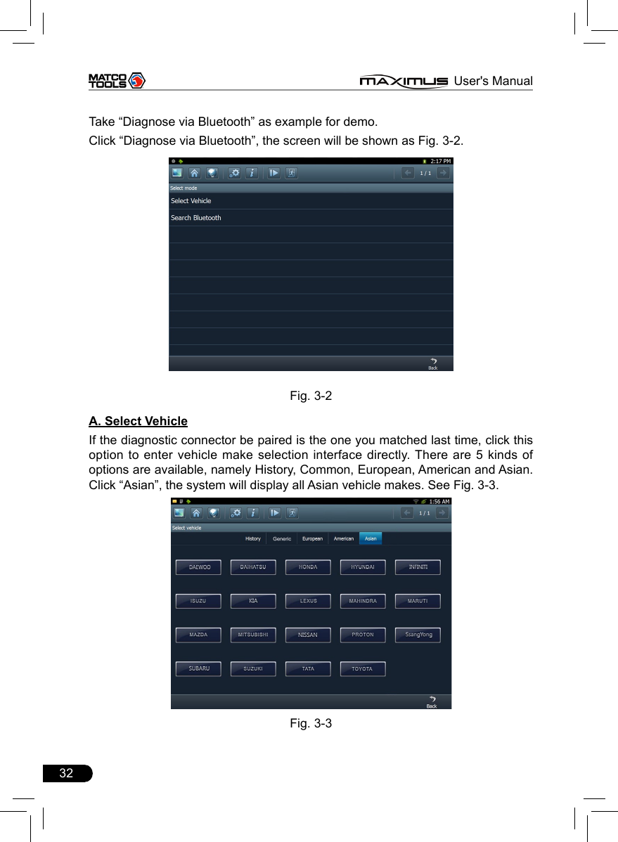
![33 MAXIMUS User's ManualClick the desired one (for example, DEMO) in Common to enter the software version selection screen. See Fig. 3-4.Fig.3-4Choose one version, and click [OK], the system starts resetting and then validates the diagnostic connector. If ok, it will enter demo menu interface. Choose the desired one and start diagnosing demo.B. Search BluetoothThis option is used to search the bluetooth device. Click it to start searching, then choose the desired one from the result list to pair. After pairing, the system will obtain the connector information and then go into the vehicle selection interface directly. Notes: 1. The bluetooth device to be paired must be the diagnostic connector manufactured by LAUNCH, or else MAXIMUS does not work properly.2. While diagnosing via Bluetooth, the effective communication distance between MAXIMUS and the diagnostic connector is about 20m.Detailed operations are as follows:Click “Search Bluetooth” to enter Fig. 3-5.](https://usermanual.wiki/Launch-Tech/M431PAD.Manual/User-Guide-2014101-Page-40.png)
![34 MAXIMUS User's ManualFig. 3-5After searching, a list of bluetooth devices (Bluetooth device’s name starts with Series No. of the diagnostic connector) will be shown on the screen. See Fig.3-6.Fig. 3-6Click the desired bluetooth device, the system will display “Pairing bluetooth, please wait...”. If ok, “Pairing bluetooth succeed! Searching port, please wait...” will be shown on the screen, otherwise, “Pairing bluetooth failed!” will appear on the screen. Click [Back] to return to the previous screen. After linked, the system will enter vehicle selection interface if the included diagnostic connector is chosen.](https://usermanual.wiki/Launch-Tech/M431PAD.Manual/User-Guide-2014101-Page-41.png)
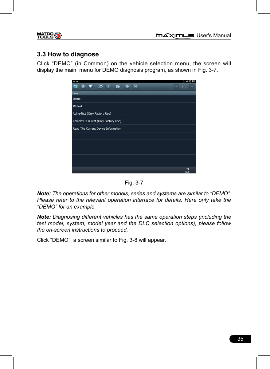
![36 MAXIMUS User's ManualFig. 3-8Click [Engine] in Figure 3-8 (If there is more than one page of system menu, click to jump to the next page), the system message “Communication is initialized…” will appear on the screen. Note: The test method is similar for different systems, here take [Engine] for an example. After communicating, the interface will skip to the function menu of [Diagnose], as shown in Figure 3-9.Fig. 3-9](https://usermanual.wiki/Launch-Tech/M431PAD.Manual/User-Guide-2014101-Page-43.png)
![37 MAXIMUS User's ManualIn Fig. 3-9, there are four functions of [Engine]: “Read trouble code”, “Clear trouble code”, “Read data stream” and “Special function”. 3.3.1 Read trouble codeClick [Read trouble code] in Figure 3-9, MAXIMUS starts executing this function. After testing, results will appear on screen, as shown in Figure 3-10.Fig.3-10Click to return to the previous screen.If the tested system has no DTCs, a message will appear on the screen, indicating that there are no DTCs in the system. 3.3.2 Clear trouble codeClick [Clear trouble code] as shown in Figure 3-9, all existing trouble codes will be cleared.](https://usermanual.wiki/Launch-Tech/M431PAD.Manual/User-Guide-2014101-Page-44.png)
![38 MAXIMUS User's ManualFig. 3-11If trouble codes are cleared successfully, a prompt message will appear on the screen, as shown in Figure 3-11. If all trouble codes have been cleared, or there are no trouble codes, “No DTCs” will appear on the screen. Click to return to the function menu of diagnostic system.3.3.3 Read datastreamClick [Read datastream] as shown in Figure 3-9, you can read the running parameters. See Fig. 3-12.Fig. 3-12](https://usermanual.wiki/Launch-Tech/M431PAD.Manual/User-Guide-2014101-Page-45.png)
![39 MAXIMUS User's ManualClick to select the desired datastream item (more datastream items can be chosen), then click , dynamic data of the selected datastream will appear on screen, as shown in Figure 3-13. Fig. 3-13To view the dynamic waveform of the selected datastream, click [Record] (and will become active) in Figure 3-14. Click to pause recording; click to stop recording, and the system will automatically save the le and a message box including the filename will pop up on the screen, where filenames follow the rules: vehicle make + system date & time and ends with .x431, for example BENZ-20130124163350.x431. To view the proper datastream record, please make sure to set the accurate data and time. (For details on how to view the recorded datastream, refer to “3.3.5 Driving record management)Click [Plot] in Fig. 3-13, the waveform of O2 will be displayed on the screen, as shown in Fig. 3-14.](https://usermanual.wiki/Launch-Tech/M431PAD.Manual/User-Guide-2014101-Page-46.png)
![40 MAXIMUS User's ManualFig. 3-14If more datastream items are selected, click [Plot-2], [Plot-4], [Plot-6], [Plot-12] and [Combination] to switch to display in multi-view window mode. Fig. 3-15 and Fig. 3-16 represent the display effect of [Plot-4] and [Combination] respectively (Combination means to display the selected datastream items into one waveform with each datastream marking in different color for easy review and analysis). Fig. 3-15 Fig. 3-163.3.4 Special functionThis option allows you to detect whether the system parameters are normal or not.Click [Special function] in function menu, the screen will be shown as Fig. 3-17.](https://usermanual.wiki/Launch-Tech/M431PAD.Manual/User-Guide-2014101-Page-47.png)
![41 MAXIMUS User's ManualFig. 3-17Note: We just take [1# injector] as an example to show how to set the special function.To detect whether [1# injector] works normally or not, click [1# injector], the screen will be shown as Fig. 3-18.Fig. 3-18Note: If [1# injector] works abnormally, the system will fail to indicate that the part has some trouble.](https://usermanual.wiki/Launch-Tech/M431PAD.Manual/User-Guide-2014101-Page-48.png)
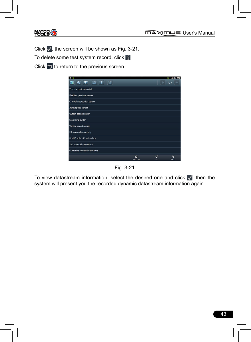
![42 MAXIMUS User's Manual3.3.5 Driving record managementView the recorded and saved datastreams and waveforms (To record, click [Record] on the running interface of datastreams).On vehicle selection menu, click in Fig. 3-19.Fig. 3-19The system switches to Fig. 3-20, listing datastream information for different vehicles and records in different time. Select the one you want to view and click in Fig. 3-20.Fig. 3-20](https://usermanual.wiki/Launch-Tech/M431PAD.Manual/User-Guide-2014101-Page-49.png)
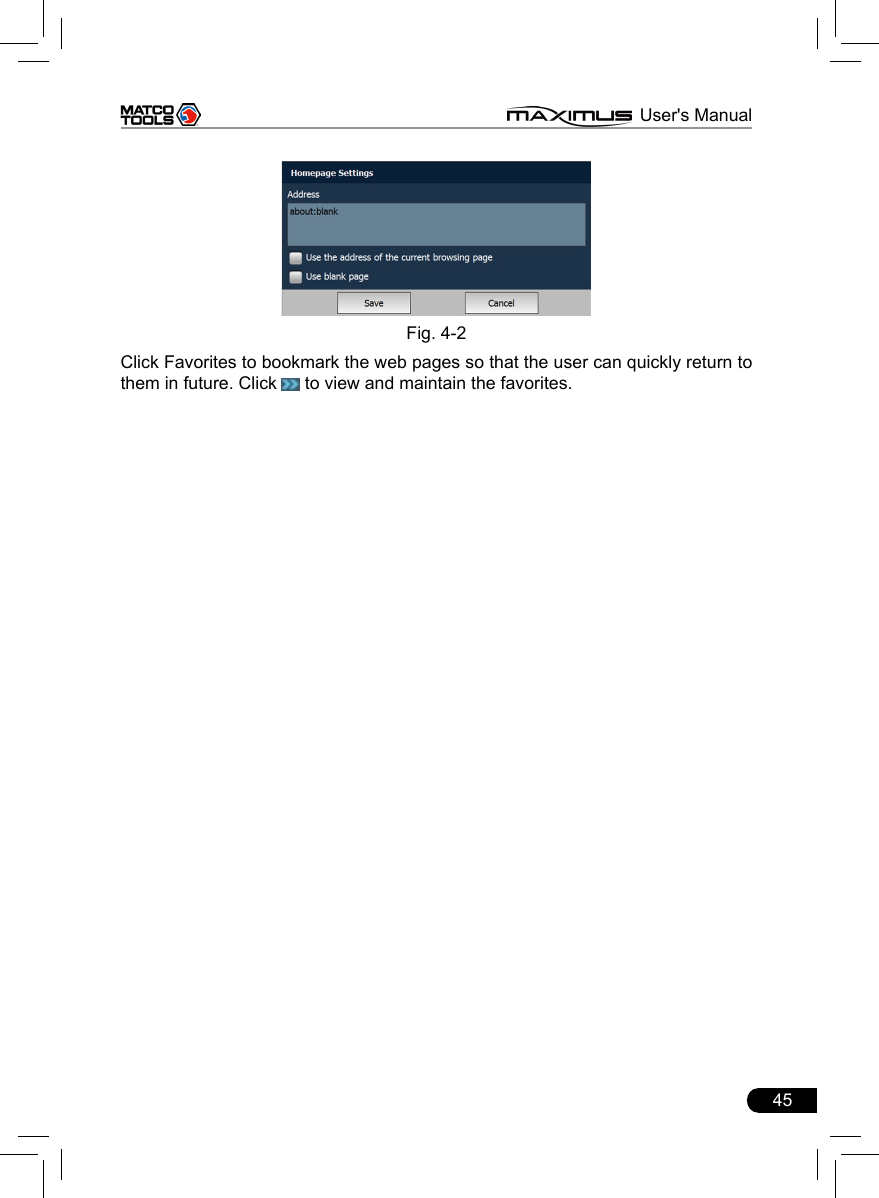
![44 MAXIMUS User's Manual4 WebbrowserBrowser is available on MAXIMUS, which helps you retrieve and search for information sources all the time.Click [Webbrowser] to enter. Fig. 4-1In address bar, use the on-screen keyboard to input the Uniform Resource Identier (URL) of the desired resource, and click to visit it. See Fig. 4-1.In search bar, input the desired information and click to search it with google search engine.Click to open a new blank page.Click to close the page.Click , a dialog box similar to Fig. 4-2 will appear on the screen.Check the box “Use the address of the current browsing page” and click “Save”, the system will set the current web page as the homepage. Next time you launch the browser, it will open the homepage link by default. If “Use blank page” is checked , homepage will be configured as a blank page and the browser will display a blank page once you open the browser. Note: Only one homepage can be set.](https://usermanual.wiki/Launch-Tech/M431PAD.Manual/User-Guide-2014101-Page-51.png)
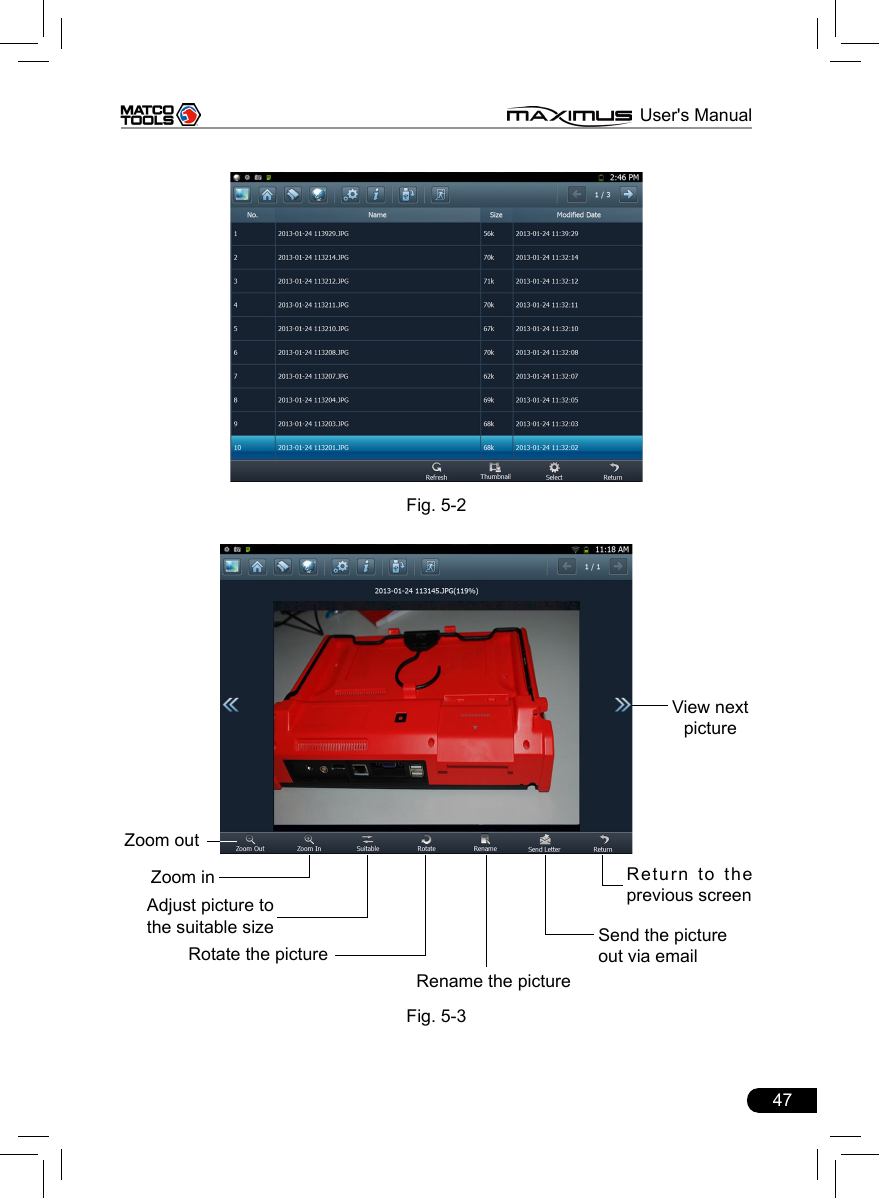
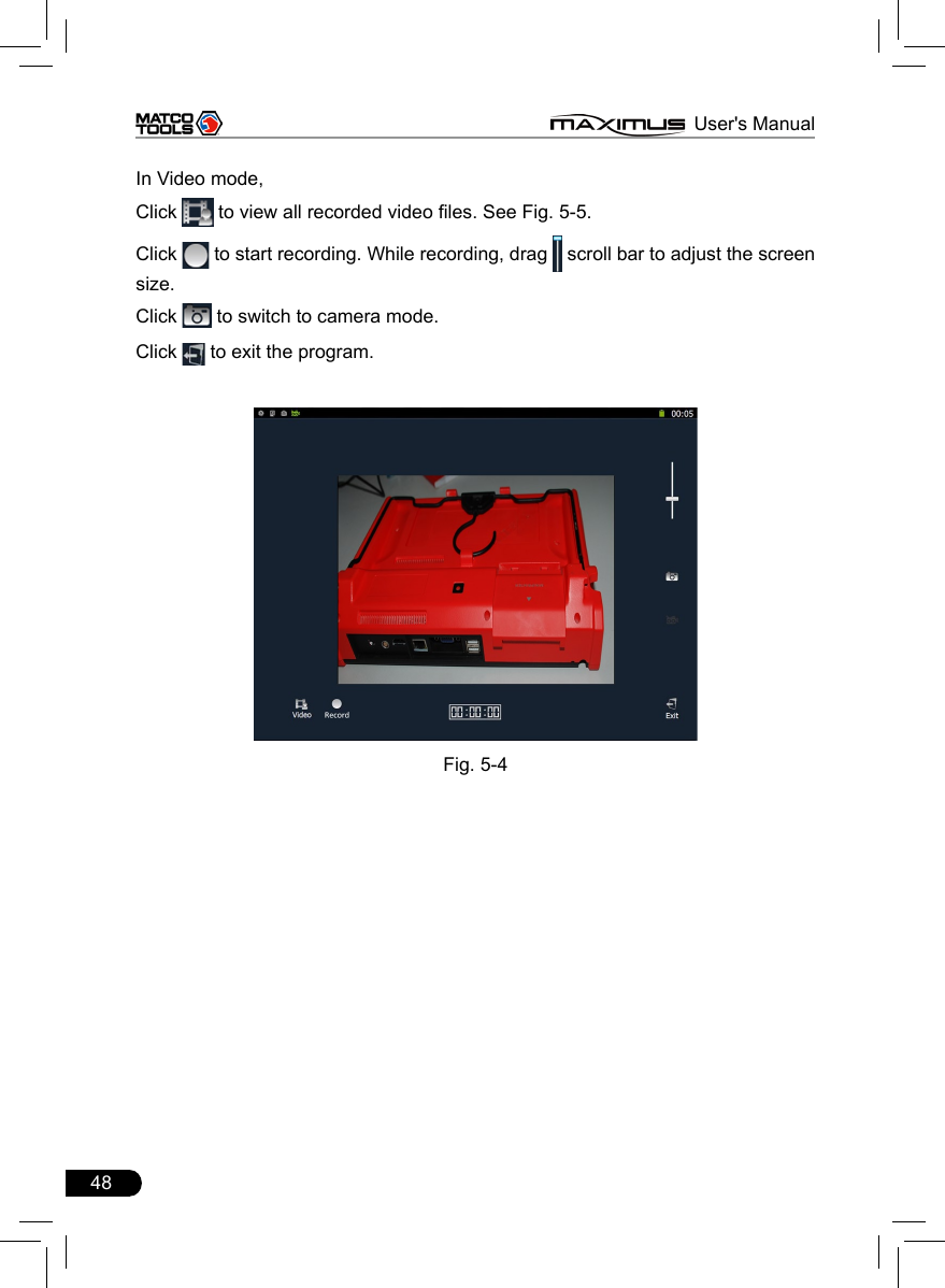
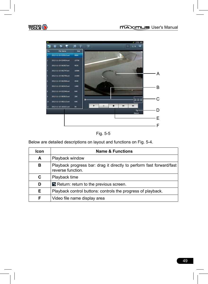
![46 MAXIMUS User's Manual5 CameraMAXIMUS is equipped with a 1.3 mega pixel lens for your photographing and video recording. Pictures are taken in .jpg format and videos are recorded in .avi format. All pictures and videos are saved in relevant module folder in “My Data” where users can browse and replay it. Click [Camera], the screen will enter video recording interface as shown in Fig. 5-1.Fig. 5-1In Camera mode,Drag scroll bar to adjust the screen size.Click to switch to video mode. See Fig. 5-4.Click to take a picture.Click to view all photos that has been already taken. See Fig. 5-2. In Fig. 5-2, click to refresh the current page. Click to switch to thumbnail mode. click the desired one in thumbnail mode to open it. See Fig. 5-3. Click , a checkbox will appear before each image file, click “Select all” to choose all les or check the desired box to select les as desired. To deselect it, click “Cancel Selection”. Once les are selected, click “Delete” to remove it; click “Export” to export it to U-disk (To perform export, a USB storage device must be inserted).Click to exit the program.](https://usermanual.wiki/Launch-Tech/M431PAD.Manual/User-Guide-2014101-Page-53.png)
![50 MAXIMUS User's Manual6 Message CenterMAXIMUS provides message center function, by which you can send E-mail to us once you come across any question or problem unresolved, and we will give you professional answer in time.To use this function, make sure that you have registered your product successfully and network is properly congured.6.1 Read messageClick [Message Center] on the main menu, the system will enter a screen similar to Fig. 6-1. Fig. 6-1Input your user name/CC/Email, then click [Log In] to enter the message center main menu. If you have not registered your product, please click [New Register] to start registering. For details on how to register, please refer to item 8.1 Register in Chapter 8 Update. In mailbox interface, there are four items available: Inbox, Sentbox, Broadcasting messages and Draft. Select one, and click it to read the details.6.2 New messageClick [ ] on the message center main menu screen, message writing interface appears on the screen.](https://usermanual.wiki/Launch-Tech/M431PAD.Manual/User-Guide-2014101-Page-57.png)
![51 MAXIMUS User's ManualClick title or content edit box, the on-screen keyboard will appear automatically, use it to input or write down the title and contents by stylus manually.Button descriptions:[Attachment]: click to add an attachment.[]: send the message.[]: save a message that is not nished or will be sent later.[]: return to the previous screen.When a new message is nished, click [ ] to send. If the message is sent out successfully, a prompt message will pop up. If the message fails to send out, a dialog box will appear on the screen. Click [OK] to send it again, or click [Cancel] to cancel sending.](https://usermanual.wiki/Launch-Tech/M431PAD.Manual/User-Guide-2014101-Page-58.png)
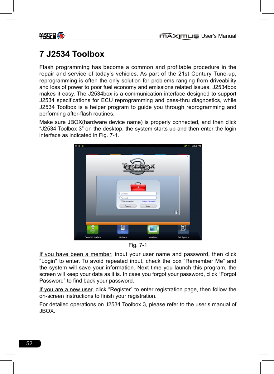
![53 MAXIMUS User's Manual8 UpdateMAXIMUS provides quick and easy software update service, by which you can enjoy all update services including download and update the software. Note: Enter the update center, vehicle software which can be updated are default to be checked, you can click [Upgrade] to perform one-key update. You can also click [Opt] to select all or deselect all. 8.1 Register8.1.1 Register your informationTo operate this device, you have to experience a product registration. After entering the function module, a screen similar to Fig. 8-1 will appear.Fig. 8-1A. In case you are a new userClick [OK] to read service terms. After reading all items, click [Agree], a registration page as indicated in Fig. 8-2 will appear automatically. Once registering is complete, this page will never appear again.](https://usermanual.wiki/Launch-Tech/M431PAD.Manual/User-Guide-2014101-Page-60.png)
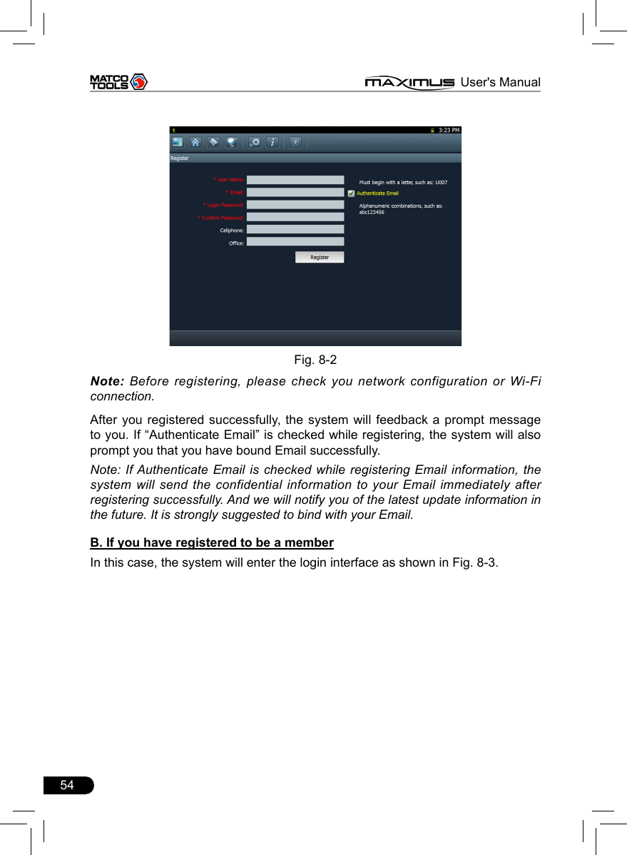
![55 MAXIMUS User's ManualFig. 8-3Click [Login] to enter update center.8.1.2 Register your productAfter registering your personal information, the screen will enter the product registration page. Fig. 8-4Product SN is printed on the bottom of MAXIMUS. While purchasing this product, you will be offered one envelop, in which there is the registration password](https://usermanual.wiki/Launch-Tech/M431PAD.Manual/User-Guide-2014101-Page-62.png)
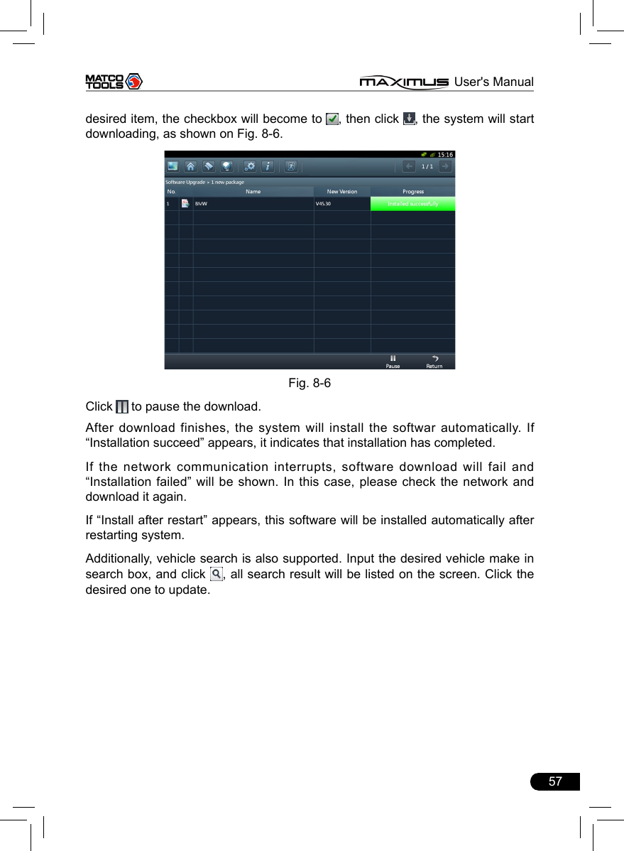
![56 MAXIMUS User's Manual(secret). Complete lling the information and click [Submit] to proceed to the next step. After registering your product, the system will enter update center. 8.2 UpdateWhile updating, make sure your network (wired or Wi-Fi) works properly, then click “One-click Update” to enter Fig. 8-5.Fig. 8-5 In Fig. 8-5, there are 3 options: Upgradable, Updated and History Diagnostic. For details, please refer to the table as below:Option FunctionsUpgradable View all upgradable softwares including main unit software and diagnostic softwareUpdated View all updated softwaresHistory Diagnostic Update diagnostic software of certain vehicle makeIf a upgradable version is available for certain software, the checkbox close to it will be selected by default.By default, all software items are selected.Click “Opt” in title bar to deselect all or select all.If the content is more than one page, click / to turn pages.Click to refresh the page.To select certain items, click “Opt” to deselect the checked mark, then click the](https://usermanual.wiki/Launch-Tech/M431PAD.Manual/User-Guide-2014101-Page-63.png)
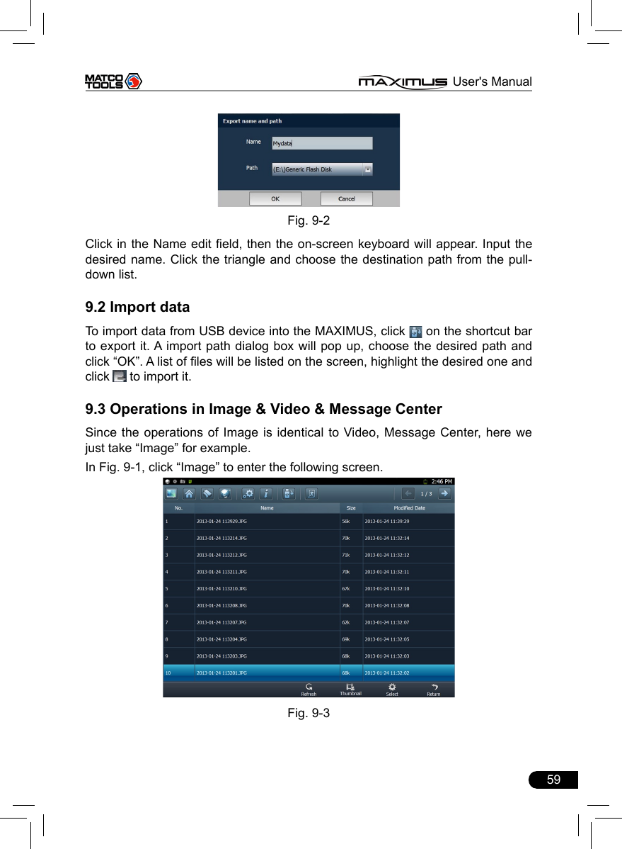
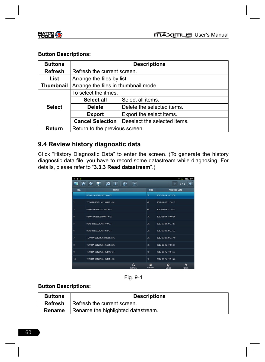
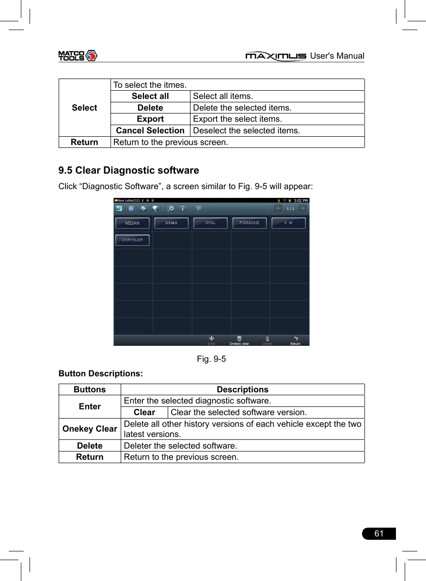
![58 MAXIMUS User's Manual9 My dataThis option enables you to manage user data, including diagnostic data log, photos, videos. Moreover, you can perform browse, view, clear, and export etc. Data export is supported on all other options except Diagnostic software.In main menu of MAXIMUS, click [My data], the screen will be displayed as Fig. 9-1.Fig. 9-1For details, please see the following Table 9-1.Options DescriptionsImage Saves all photographing les.Video Saves all video les which users use Video to record.History Diagnostic Data View and play back the history diagnostic data.Diagnostic Software Keeps all diagnostic softwares you ever applied. Message Center All received pictures from letterbox are kept in it.9.1 Export dataTo export all data saved in My Data successfully, please be sure that the USB device has been inserted into the USB port of MAXIMUS. Click “Select” on the bottom of the screen, a check box will appear on upper right corner of each option, tick the box(except Diagnostic Software), and click to export it to USB device. Alternatively, you can also click on the shortcut bar to export it.Note: Before performing export operation, you have to select the items you want to export.](https://usermanual.wiki/Launch-Tech/M431PAD.Manual/User-Guide-2014101-Page-65.png)
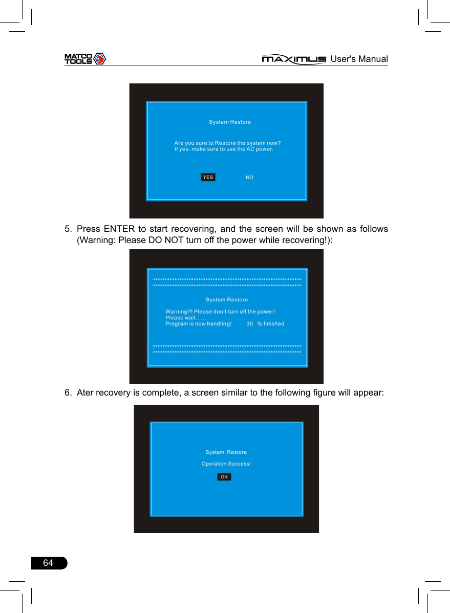
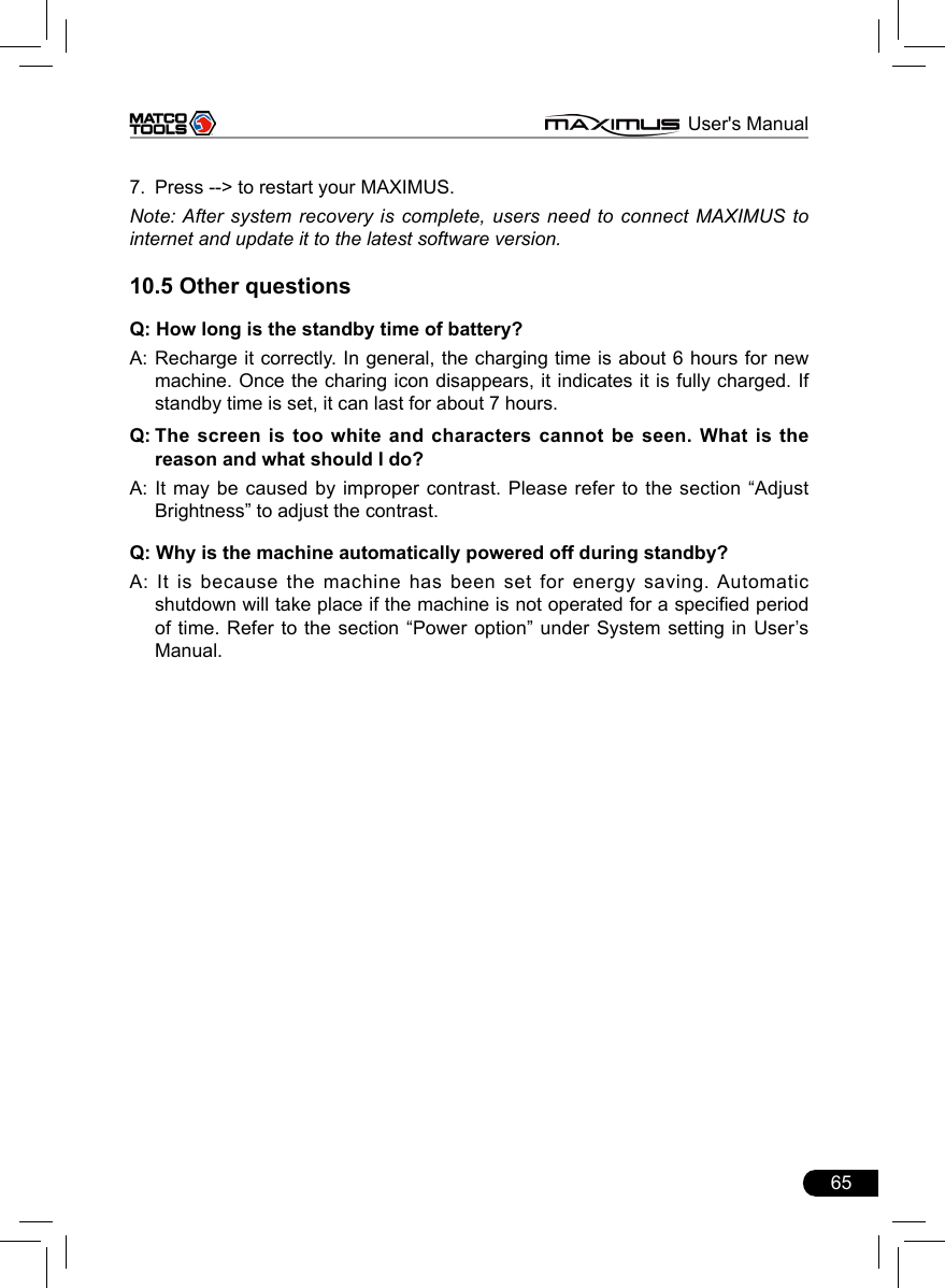
![63 MAXIMUS User's ManualQ: Why MAXIMUS fails in communication with ECU?A: ECU does not respond. Please try to use the latest update tool to upgrade to the latest diagnostic program.10.3 About systemQ: Main screen blinks at the moment when engine ignition.A: It results from electromagnetic interference and this is normal phenomena.Q:Diagnose interrupted during diagnosing process. A: Caused by electromagnetic disturbing or poor connecting.Q: There is no response when communicating with on-board computer.A: Please conrm the proper voltage of power supply and check if the throttle has been closed, the transmission is in the neutral position, and the water is in proper temperature.Q: The systems equipped with the vehicle can not be diagnosed.A: DLC of some early models is separated; refer to User’s Manual for details.Q: The fault code storage is blank.A: Usually, it’s the “suquela” for shared circuit. Please locate and analyze the most similar fault code and its circuit.10.4 System RecoveryQ: Software runs improperly.A: Solution: Try to use the one-key recovery to restore MAXIMUS to the default settings. System recovery does not affect any data (including the downloaded diagnostic software) that users saved before. Follow the steps described as below to proceed system recovery: 1. Disconnect all devices from MAXIMUS and turn it off.2. Use the included power adaptor to supply power to MAXIMUS.3. Insert an external USB keyboard into the USB port of MAXIMUS.4. Press [POWER] button on MAXIMUS, then press and hold F12 on the keyboard until the system enters recovery mode:](https://usermanual.wiki/Launch-Tech/M431PAD.Manual/User-Guide-2014101-Page-70.png)