Launch Tech M431PAD Automotive Diagnostic Computer User Manual Manual
Launch Tech Co., Ltd. Automotive Diagnostic Computer Manual
Contents
- 1. Manual
- 2. Addendum
Manual

Version: V1.00.000
Revised date: 2013-01-16

I
MAXIMUS User's Manual
FCC INFORMATION
This device complies with Part 15 of the FCC Rules. Operation is subject to the
following two conditions:
1. This device may not cause harmful interference, and 2. This device must
accept any interference received, including interference that may cause
undesired operation.
Note: This equipment has been tested and found to comply with the limits for
a Class B digital device, pursuant to part 15 of the FCC Rules. These limits
are designed to provide reasonable protection against harmful interference
in a residential installation. This equipment generates, uses and can radiate
radio frequency energy and, if not installed and used in accordance with the
instructions, may cause harmful interference to radio communications. However,
there is no guarantee that interference will not occur in a particular installation. If
this equipment does cause harmful interference to radio or television reception,
which can be determined by turning the equipment off and on, the user is
encouraged to try to correct the interference by one or more of the following
measures:
— Reorient or relocate the receiving antenna.
— Increase the separation between the equipment and receiver.
— Connect the equipment into an outlet on a circuit different from that to which
the receiver is connected.
— Consult the dealer or an experienced radio/TV technician for help.
Caution: Any changes or modifications not expressly approved by the party
responsible for compliance could void the user’s authority to operate this
equipment.
RF Exposure: A distance of 20 cm shall be maintained between the antenna
and users, and the transmitter module may not be co-located with any other
transmitter or antenna.

II
MAXIMUS User's Manual
All rights reserved! No part of this publication may be reproduced, stored in
a retrieval system or transmitted, in any form or by any means of electronic,
mechanical, photocopying and recording or otherwise, without the prior written
permission of LAUNCH.
This manual is designed only for the use of this unit. LAUNCH is not responsible
for any use of this manual on the other units.
The manual and all the samples herein can be changed without prior notice.
Neither LAUNCH nor its affiliates shall be liable to the purchaser of this unit
or third parties for damages, losses, costs or expenses incurred by purchaser
or third parties as a result of: accident, misuse, or abuse of this unit, or
unauthorized modications, repairs, or alterations to this unit, or failure to strictly
comply with LAUNCH operating and maintenance instructions.
LAUNCH shall not be liable for any damages or problems arising from the use of
any options or any consumable products other than those designated as Original
LAUNCH Products or LAUNCH Approved Products by LAUNCH.
Notice: other product names used herein are for identication purposes only and
may be trademarks of their respective owners. LAUNCH disclaims any and all
rights in those marks.
This device is only for professional technicians and maintenance personnel.
Registered Trademark
LAUNCH is a registered trademark of LAUNCH TECH. CO., LTD. (LAUNCH)
in China and other countries. In other countries where any of the LAUNCH
trademarks, service marks, domain names, logos and company names is
not registered, LAUNCH claims other rights associated with unregistered
trademarks, service marks, domain names, logos and company names. Other
products or company names referred to in this manual may be trademarks
of their respective owners. You may not use any trademarks, service marks,
domain names, logos or company name of LAUNCH or any third party without
permission from the owner of the applicable trademarks, service marks, domain
names, logos or company name.
You may visit LAUNCH at http://www.dbscar.com for the information of Launch’s
MAXIMUS and the other specialized diagnostic tools, or contact Launch by
visiting http://www.cnlaunch.com or writing to Customer Center, LAUNCH TECH.
CO., LTD., Launch Industrial Park, North of Wuhe Avenue, Banxuegang, Bantian,
Longgang, Shenzhen, Guangdong. P.R. China, to request written permission to
use materials on this manual for purposes or for all other questions relating to
this manual.

III
MAXIMUS User's Manual
Precautions on Operating Vehicle’s ECU
Do not disconnect the vehicle inner consumer when the ignition switch is on. •
High voltage transients may encounter at the moment of disconnecting, which
may damage the sensors and the ECU.
Protect the computer from magnetic object (such as wireless speaker) •
Do cut off the power supply of ECU system before welding on the vehicle.•
Pay more attention to the ECU and the sensors when the operation is next to •
them.
Ground yourself when you disassemble PROM, otherwise ECU and sensors •
will be damaged by static electricity.
Do not use the pointer ohmmeter instead of DMM to test the ECU and the •
sensor without special requirement.
Do not test electric devices in relation with ECU with a test lamp unless •
otherwise expressly provided.
Do wear a metal ground strip that one end around your wrist and the other to •
the vehicle body when you get in and out the vehicle.
Do connect ECU harness connector rmly, otherwise electro elements, such •
as IC inside ECU, will be damaged.
Precaution on Operation
The appliance is a sophisticated electronic device, never have it clashed •
when in use.
Make sure the appliance is properly connected to the DLC to avoid •
communication interruptions. During operation, keep the screen upward and
leveled.
Don’t disconnect the wired network or Wi-Fi network while software updating •
or sending E-mail, otherwise, it will be interrupted.
After the operation, the stylus shall be inserted into the hole on the back of •
the main unit, and put away the cable and connector, etc accessories to the
box to avoid the lost.
Handle with care. Avoid collision. Unplug the power after operation.•
IV
MAXIMUS User's Manual
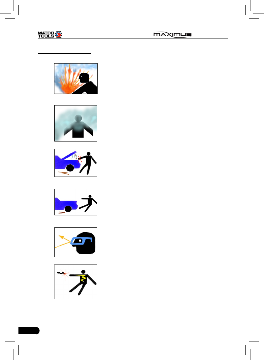
Safety Precautions
Automotive batteries contain sulfuric acid •
that is harmful to skin. In operation, direct
contact with the automotive batteries should
be avoided. Pay attention not to splash the
sulfuric acid into eyes. Keep the ignition
sources away from the battery at all times.
Engines produce various poisonous •
compounds (hydrocarbon, carbon
monoxide, nitrogen oxides, etc,) which
should be avoided. The vehicles shall be
tested in a well-ventilated area.
Avoid contacting high temperature •
assembly such as water tank and vent-pipe
as the temperature of the running engine is
very high.
Before starting engine, put the speed lever •
in the neutral position or in the P position to
avoid injury.
Wear an ANSI-approved eye shield when •
testing or repairing vehicles.
If you use the battery as a power source, •
connect the RED (+) battery clip to the
positive of the vehicle battery and the
BLACK (-) battery clip to the negative.

V
MAXIMUS User's Manual
Content
1 Foreword ......................................................................................................... 1
1.1 Product Introduction ......................................................................................1
1.2 Product Features ...........................................................................................1
1.3 Product Functions..........................................................................................1
1.4 Technical Specications ................................................................................ 2
2 About MAXIMUS ............................................................................................. 3
2.1 MAXIMUS main unit ...................................................................................... 3
2.1.1 Front View ............................................................................................3
2.1.2 Rear view..............................................................................................4
2.1.3 Docking Station ....................................................................................6
2.2 Diagnostic Connector .................................................................................... 6
2.3 MAXIMUS Accessory Checklist .....................................................................7
2.4 Getting to know MAXIMUS ............................................................................8
2.4.1 Powering on MAXIMUS ........................................................................8
2.4.2 Function items, UI layout and on-screen keyboard .............................. 8
2.4.3 Settings...............................................................................................14
3 How to diagnose ...........................................................................................28
3.1 Preparation and Connections ......................................................................28
3.1.1 Preparation .........................................................................................28
3.1.2 Connecting MAXIMUS........................................................................28
3.2 Start diagnosing...........................................................................................30
3.3 How to diagnose ..........................................................................................35
3.3.1 Read trouble code .............................................................................. 37
3.3.2 Clear trouble code .............................................................................. 37
3.3.3 Read datastream ................................................................................38
3.3.4 Special function .................................................................................. 40
3.3.5 Driving record management ............................................................... 42
4 Webbrowser ..................................................................................................44
5 Camera ..........................................................................................................46
6 Message Center ............................................................................................50
6.1 Read message ............................................................................................50
6.2 New message ..............................................................................................50
7 J2534 Toolbox ..............................................................................................52

VI
MAXIMUS User's Manual
8 Update ...........................................................................................................53
8.1 Register ....................................................................................................... 53
8.1.1 Register your information ...................................................................53
8.1.2 Register your product ......................................................................... 55
8.2 Update .........................................................................................................56
9 My data .......................................................................................................... 58
9.1 Export data .................................................................................................. 58
9.2 Import data ..................................................................................................59
9.3 Operations in Image & Video & Message Center ........................................59
9.4 Review history diagnostic data ....................................................................60
9.5 Clear Diagnostic software............................................................................61
10 FAQ .............................................................................................................. 62
10.1 About hardware .........................................................................................62
10.2 About software ...........................................................................................62
10.3 About system .............................................................................................63
10.4 System Recovery ......................................................................................63
10.5 Other questions ......................................................................................... 65

1
MAXIMUS User's Manual
1 Foreword
1.1 Product Introduction
MAXIMUS is a new generation pad computer developed for automobile
aftermarket. It is far more than a diagnostic scanner, it can also used as a pad
computer, which enables users to enjoy all functions of Windows Embedded
Standard 7 operating system. Built-in printer driver is equipped for printing once
it is connected to an external printer via USB cable. In addition to powerful
vehicle diagnosing function, MAXIMUS also provides an optional borescope
for detecting abrasion, coke and block in automobile engine, cylinder, fuel line,
engine, mufer etc. It supports wired and wireless network, and VGA & HDMI
interfaces for external display.
It features smart design, full color touch screen and easy to operate.
1.2 Product Features
High performance pad computer runs rapidly and stably.•
Wi-Fi communication, wireless network, easy to update and feedback.•
It possesses advanced diagnostic functions from X-431 super scanner, •
almost can diagnose all vehicles from Asia, Europe and America makes, and
testing speed is greatly improved.
1.3 Product Functions
Powerful and rapid diagnosing: it can diagnose most electrical control •
systems for any model from Asia, Europe and America makes. Diagnostic
function and software update keep pace with other products.
Wi-Fi connection: easy to realize online update and feedback.•
Ethernet interface for connecting wired network.•
Web browser: Users can make online search and visit any website.•
VGA and HDMI interfaces for connecting the external displays.•
Provides automobile borescope (optional).•
USB ports: to connect U disk and other extending function modules such as •
scopebox, sensorbox and batterybox.
Camera & Video recorder: built-in 1.3 mega pixels camera lens for •
photographing and video recording.

2
MAXIMUS User's Manual
1.4 Technical Specications
A. Main Unit
Operating system: Windows Embedded Standard 7
Power: 12V input
Battery: 7400mAh lithium polymer battery
LCD: 9.7 inch touch screen
CPU: dual-core 1.6GHz
Memory: 2GB
Hard disk: 16GB SSD
Bluetooth: supports Bluetooth2.1
Wi-Fi: supports 802.11 b/g/n
Camera Lens: 1.3 mega pixels
C.Others
Working temperature: -10℃ ~ 55℃(14 ~131℉)
Storage temperature: -20℃ ~ 70℃(-4 ~158℉)
Relative humidity: 20% ~ 90%
3
MAXIMUS User's Manual
2 About MAXIMUS
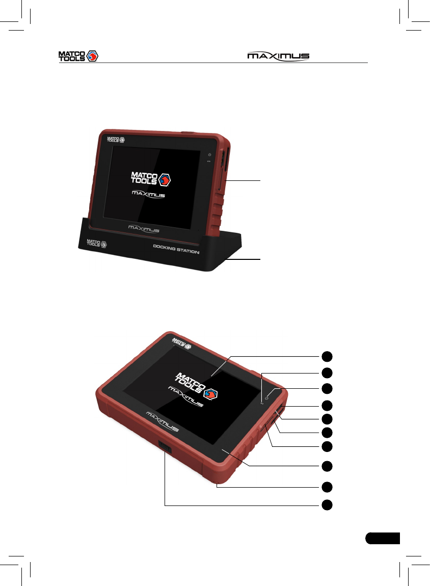
2.1 MAXIMUS main unit
MAXIMUS
main unit
Docking station for
MAXIMUS main unit
Fig. 2-1 MAXIMUS Diagram
2.1.1 Front View
1
2
3
5
4
6
7
10
9
8
4
MAXIMUS User's Manual
Table 2-1 formulates interfaces and indicators of MAXIMUS(front)
No. Name Descriptions
1 Touch screen Color touch screen for displaying. On-screen
keyboard and handwriting input are supported.
2Communication
indicator
It flashes while MAXIMUS communicates with
the included diagnostic connector.
3 Power indicator It lights up while MAXIMUS is on or in use.
4 Audio in port To connect audio device, such as amplier.
5 Audio out port To connect earphone
6 Air intake vent
7 SD card slot To store SD card
8 Microphone
9 Stylus For clicking operation
10 Charging slot Place MAXIMUS on the docking station for
charing.
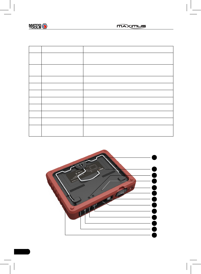
2.1.2 Rear view
11
12
14
13
15
16
17
18
19
20
21
22
23
5
MAXIMUS User's Manual
Table 2-2 formulates interfaces and indicators of MAXIMUS(rear)
No. Name Descriptions
11 Hook/stand
Use ngers to lift the hook up, then hang it on
the target object; To place it on a desk, install
it on the docking station directly or unfold the
hook as an stand to support MAXIMUS.
12 Battery cover 7400mAh lithium polymer battery is installed
below it.
13 Speakers
14 Camera lens To take photos or record video
15 Power button Press once to turn it on; keep it pressed for a
while to turn it off.
16 Slot for diagnostic
connector Only for housing the diagnostic connector
17 USB port
To connect USB devices. While extending
MAXIMUS function, it is to be connected to
Scopebox, Sensorbox or batterybox.
18 VGA port To connect an external projector or monitor etc
19 Ethernet port To connect Ethernet cable for wired network
20 HDMI port To connect an external projector or monitor
with HDMI interface
21 Borescope interface To connect an Borescope
22 Power interface To connect the included power adaptor
23 Air vent To exhaust heat to ensure a normal
temperature.
6
MAXIMUS User's Manual
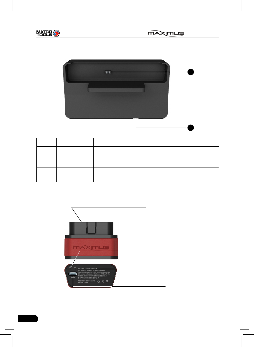
2.1.3 Docking Station
24
25
No. Name Descriptions
24 Charging port
Align the charging port located on the bottom of the
MAXIMUS with it and make sure the MAXIMUS main
unit is rmly sitted on the docking station.
25 Jack for power
cord Insert the power cord for docking station into this jack.
2.2 Diagnostic Connector
OBD 2 16 PIN connector
Micro USB port
Communication indicator*2
Power indicator*1
7
MAXIMUS User's Manual
Notes:
*1. It keeps on when the connector is connected.
*2. It lights up while the connector is communicating with your MAXIMUS.
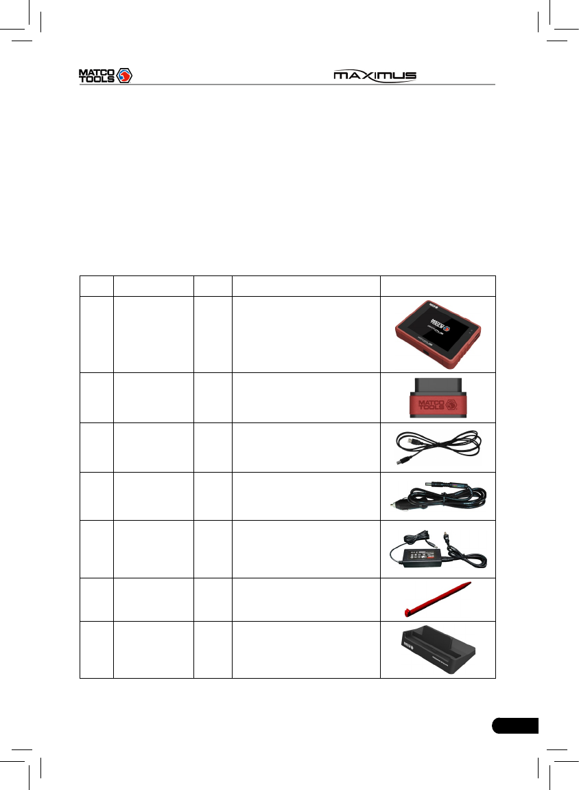
2.3 MAXIMUS Accessory Checklist
Common accessories for each MAXIMUS are same, but for different destinations,
the accessories of MAXIMUS (such as diagnostic software, testing connectors)
may vary. Please consult from the local agency or check the package list supplied
with MAXIMUS together.
Table 2-3: MAXIMUS common accessories and descriptions
No. Name Qt. Descriptions Picture
1MAXIMUS
main unit 1
To connect MAXIMUS
main unit to the diagnostic
connector
2Diagnostic
connector 1To connect to vehicle’s
DLC.
3 USB cable 1 To connect MAXIMUS and
diagnostic connector
4Cigarette
lighter cable 1
To obtain power supply
from vehicle’s cigarette
lighter
5Power
adaptor 1
To convert 100~240V AC
power supply to 12V DC
power supply.
6 Stylus 1 For clicking or writing on
the screen
7Docking
station 1For docking and charging
your MAXIMUS
8
MAXIMUS User's Manual
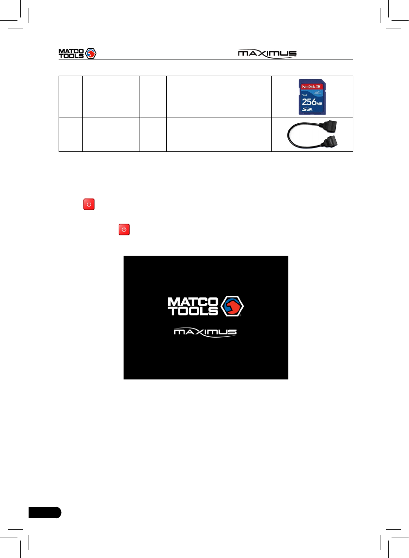
8SD card
(optional) 1 For extending memory
9
OBD II
extension
cable
1
2.4 Getting to know MAXIMUS
2.4.1 Powering on MAXIMUS
Press on the MAXIMUS to turn it on, the screen will begin to initialize, as
shown in Fig.2-2.
Note: Pressing for 8 seconds can power it off. Doing so is not suggested,
please click "Exit system" on the main menu to turn it off.
Fig. 2-2
After the system completes initializing, a message "Please register this unit
with LAUNCH before continuing. (An active internet connection is required)" will
appear on the screen. To register, click "Register it now" to enter registration
interface(For detailed on how to register, please refer to Chapter 8 Update. If
you have registered, this dialog box will not appear.); click "Register it later" to
register later and it will enter the main menu screen.
9
MAXIMUS User's Manual
2.4.2 Function items, UI layout and on-screen keyboard
A. Function menus
a. Below lists all function items and its detailed descriptions of MAXIMUS:
Function Descriptions
Diagnostic To check vehicle's working state, nd out trouble location
and cause.
Camera To take photos or record video.
Webbrowser To browse the internet.
Message
Center
Feedback the trouble of the device or vehicle to us via
E-mail and we will give you a professional reply in time.
Identix To visit www.identix.com.
Settings To make settings to system functions.
J2534 Toolbox Supports J2534-1 ashing, additional hardware required.
One-click
Update
Perform one click to update vehicle software automatically.
It is necessary to complete registering for the rst time.
My data
To manage user data, including diagnostic log, photos and
video les etc. Data view, rename, clear, import and export
are supported.
Windows Enter Windows 7 operating system.
Exit system To turn the unit off or restart it.
b. Below lists all optional function items and its detailed descriptions of
MAXIMUS:
Function Descriptions
Borescope To check unseen or unreachable parts or components
Oscilloscope
Rapidly determine vehicle electrical equipment and circuit
trouble, making the measurement and setting of vehicle
electrical equipment easier and more intuitive.
Ignition Display and analyze ignition waveforms, assist to detect
current status and relevant performance of the engine.
Sensor Diagnose/simulate vehicle ECU sensor trouble.
Multimeter Measure the physical parameters such as voltage,
resistance, frequency etc.
10
MAXIMUS User's Manual
BatteryTest
The most advanced conductance testing technology in the
world is applied to make vehicle battery and charging system
testing safe, rapid and easy.
B. User interface layout
1. The working area of diagnosis platform consists of 6 parts as indicated on
Fig.2-4.
B
A
C
D
E
F
Fig. 2-3 Layout of MAXIMUS Diagnosis module
11
MAXIMUS User's Manual
No. Name Notes
ATask status
bar
This area shows the running tasks and the highlighted
one is the currently displayed window. Click the area,
a task list window will pop up, click the desired one to
switch to the corresponding window.
B Shortcut bar
Provides shortcut to some commonly used functions,
such as diagnosing, web browser and settings. Click it
to toggle the function.
C Indicators
Bluetooth: highlights while bluetooth is activated.
Signal: displays the signal is strong or weak.
Battery capacity/power plug: displays the battery power
value/it is connected to external power supply.
Time: shows the current time
D Tools Includes page up & page down buttons.
EMain view
area An area for browsing or working
F Operation bar Operations for functions or options in main view area
2. Click to enter Windows 7 operating system. Please refer to Fig. 2-4.
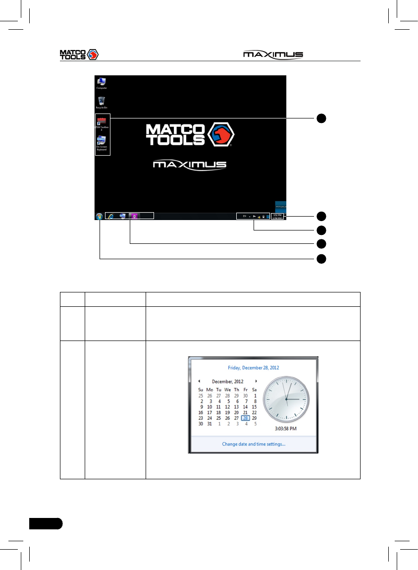
12
MAXIMUS User's Manual
G
H
I
J
K
Fig. 2-4
No. Name Notes
GProgram
shortcut
In case you choose to create a desktop icon while
installing a software, it will automatically appear on the
desktop once it has been installed successfully.
HTime display
area
Click to set time and date.
After setting, Date/Time under System tab in Settings
will keep synchronized with it and vice verse.
13
MAXIMUS User's Manual
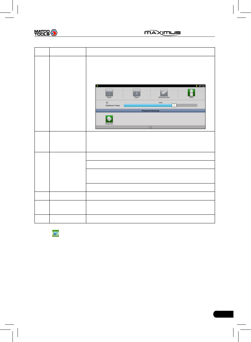
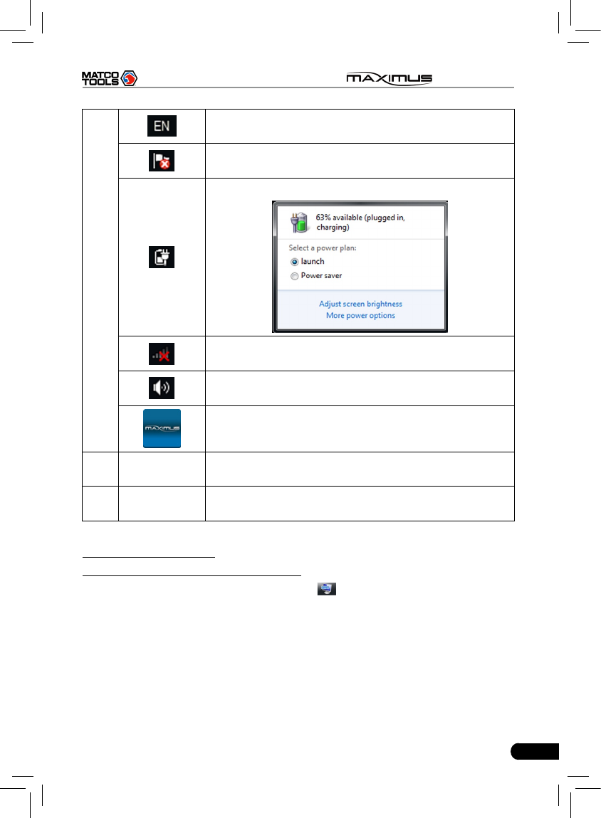
I
Click it to set the input language.
Click it to view the messages.
Click it to dene a power plan and view power status.
Network icon: Click it to congure network connection.
Click it to adjust volume.
Click it to return to MAXIMUS desktop.
JQuick Launch
bar
Click the desired icon to launch the corresponding
application.
K Start Click it to select a desired program from the pull-down
menu and execute it.
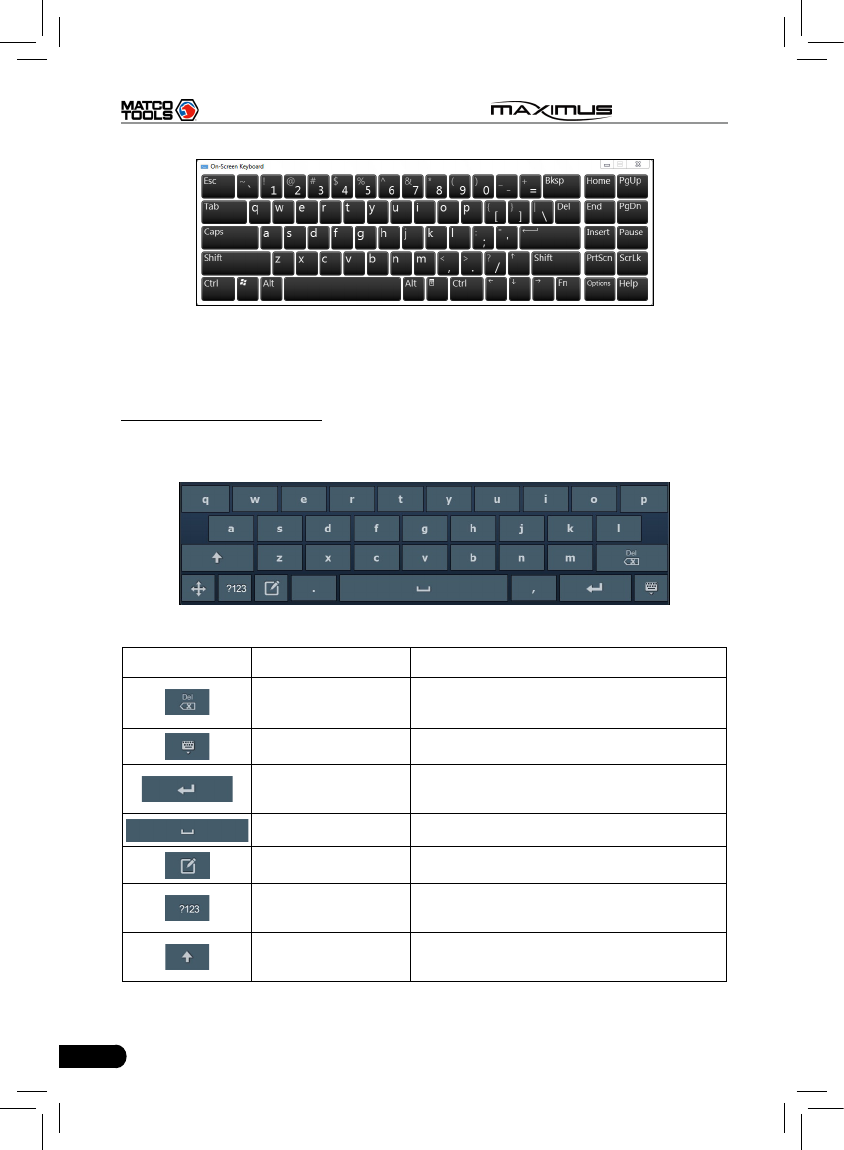
C. On-screen keyboard
1. Under Windows 7 operating system
A keyboard application is installed, click on the desktop, the on-screen
keyboard will pop up. See Fig. 2-5.
14
MAXIMUS User's Manual
Fig. 2-5
The layout of keyboard is possible to be different, but the operations of keys are
same as that of PAD computer keyboard.
2. On MAXIMUS platform
If you encounter a edit box or input area, click the blank area, a on-screen
keyboard similar to Fig. 2-6 will appear.
Fig. 2-6
Keys Name Functions
Delete Place the cursor next to the character,
and click this key to erase it.
Hide keyboard Click it to hide on-screen keyboard.
Conrm the key that causes a carriage return or
line feed.
Space Input a space.
Handwriting Switch to handwriting mode.
Number/symbol
toggle key
Toggle between number and symbol
input mode.
Caps Toggle between uppercase/lowercase
letters
15
MAXIMUS User's Manual
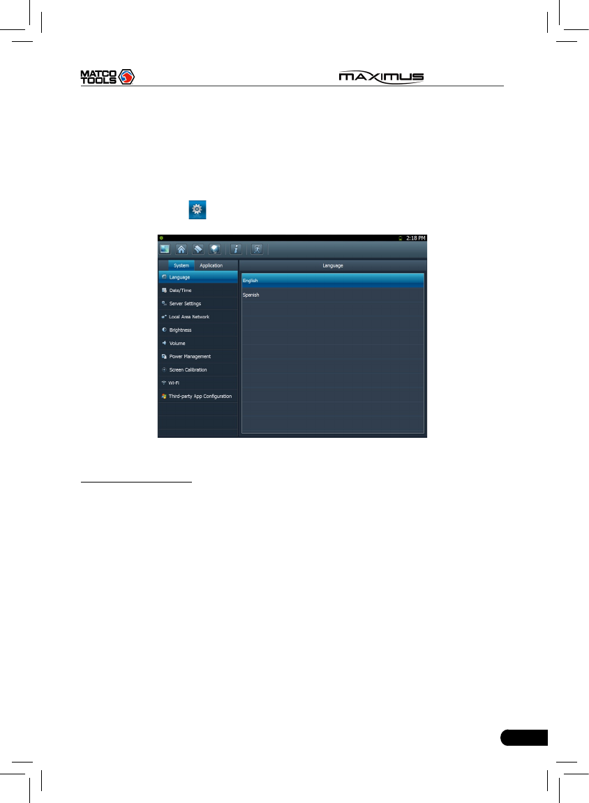
2.4.3 Settings
It includes system settings and application setting. Language setting, Date/Time,
Server Settings, Local Area Network, Brightness, Volume, Power Management,
Screen Calibration, Wi-Fi and Third-party App Configuration are available in
system setting, while application settings provide some settings related to
applications.
In main menu, click [ Settings] to enter setting interface, similar to Fig. 2-7.
Fig. 2-7
1. Language setting
This items enables you to change the system language. Due to continuous
upgrade, Language interface may vary with different software versions (Fig 2-7
is provided for reference and demo purpose).
In Fig. 2-7, click on your preferred language, the system will prompt you that
language has been changed, please close the application and then restart it.
16
MAXIMUS User's Manual
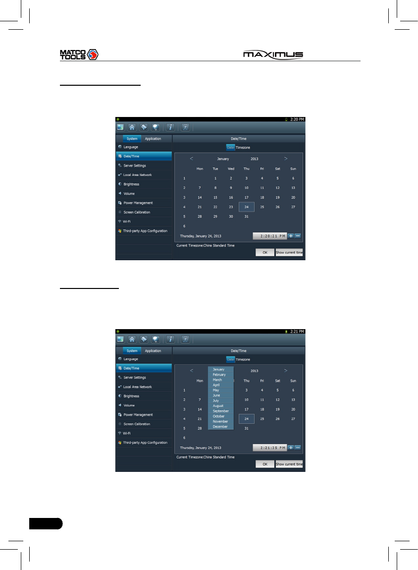
2. Date/Time Setting
This option can be used to set the system date, time and time zone.
Click “Data/Time”, the screen will appear as Fig. 2-8.
Fig. 2-8
A. Date setting
In Fig. 2-8, click </> to switch to the previous/next month. Alternatively you can
also click month or year directly and choose from the pull-down list (see Fig.
2-9). Then click on the desired date to set the date.
Fig. 2-9
17
MAXIMUS User's Manual
B. Time setting
Click on the time display area, the cursor will blink, click the +/- button next to it
to adjust it.
Click [Show current time] to display the current time.
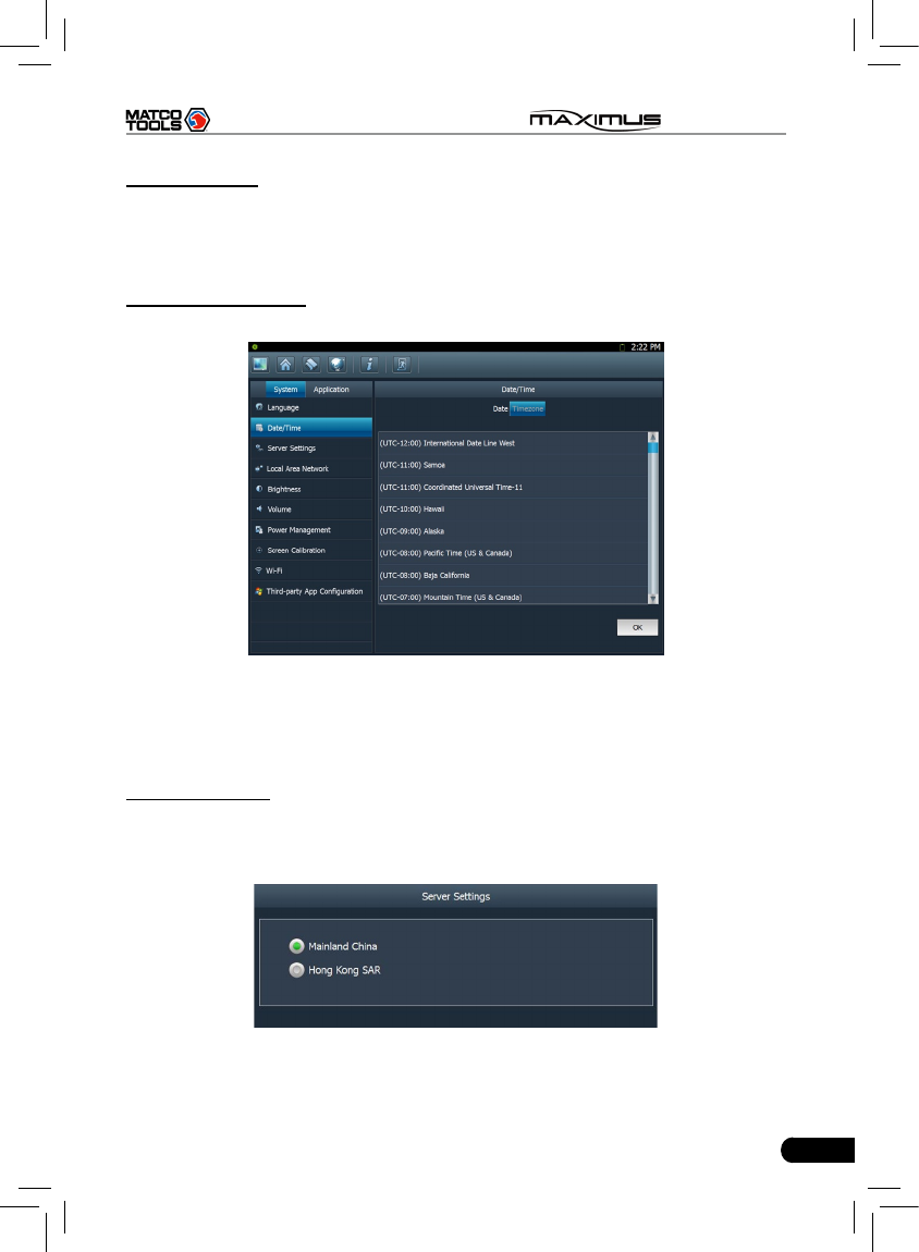
C. Time zone setting
Click [Timezone] in Fig. 2-8, a screen similar to 2-10 will appear.
Fig. 2-10
Click the desired time zone, then click [Date] to switch to date setting screen,
the time zone you have set will be displayed on the bottom of the screen and the
system time varies with the time zone.
3. Server setting
This option provide two server domains for your selection. Users can choose the
different domain according to your actual network status.
Fig. 2-11
18
MAXIMUS User's Manual
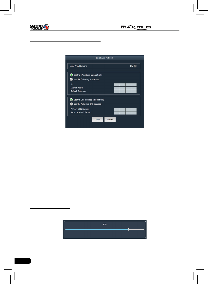
4. Local area network conguration
Click “Local Area Network”, the screen will be shown as Fig. 2-12.
Fig. 2-12
Operations:
Automatically or manually obtain IP:
A. You can select “Get the DNS address automatically” or “Use the following
DNS address” to obtain IP address.
B. You need to set DNS to manually input IP address.
Suggestion: If there is no network limited, please keep the setting as default,
that means, Get the IP address automatically and Get the DNS address
automatically should be checked. Thus, if you use DHCP to set IP address, no
other settings are needed.
Note: If you use wired network but not Wi-Fi to access Internet, please congure
network properly, otherwise, the network will become unavailable.
5. Adjust brightness
This option is used to adjust the brightness of the screen to your preference.
Fig. 2-13
19
MAXIMUS User's Manual
In Fig. 2-13, drag the slider with stylus to adjust.
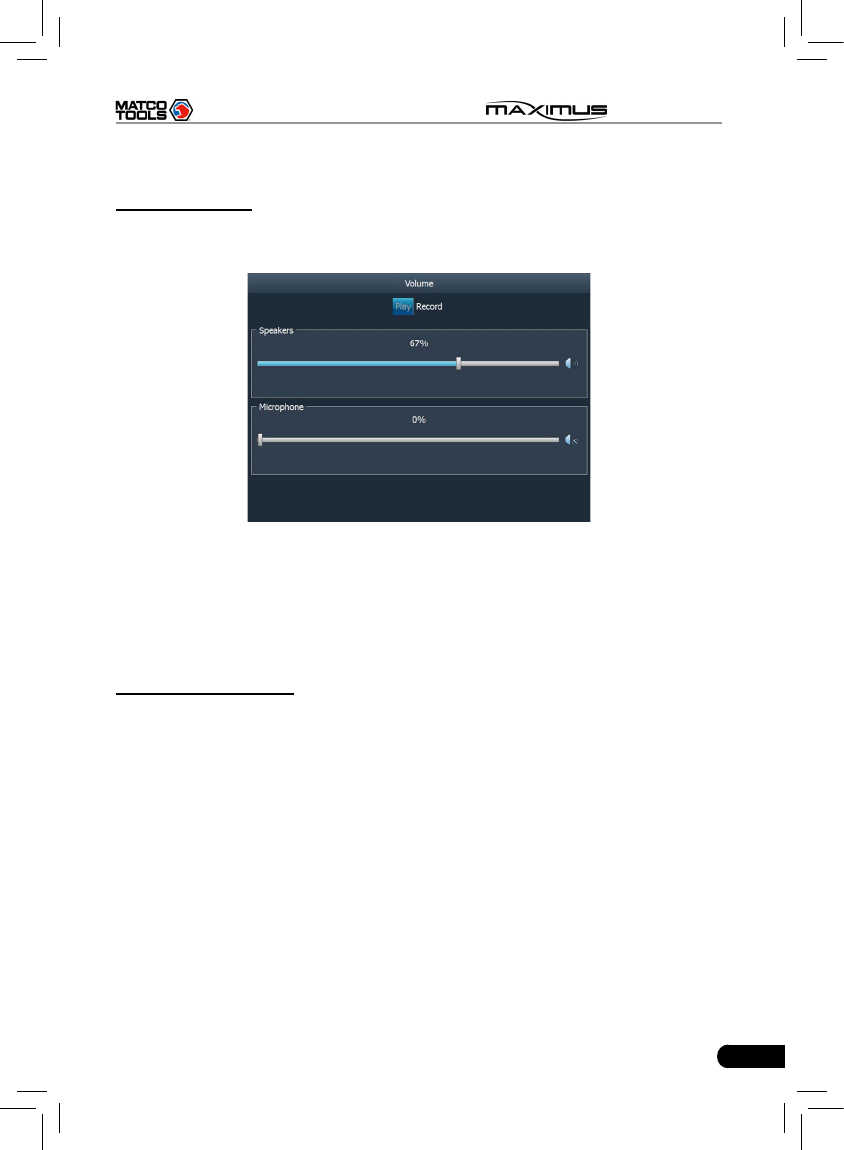
6. Adjust Volume
This option is used to adjust the volume of speakers and microphone in play &
record mode.
Fig. 2-14
In Fig. 2-14, drag the slider with stylus to adjust the volume of speakers and
microphone.
Click “Record” to adjust the volume of microphone and microphone boost while
recording.
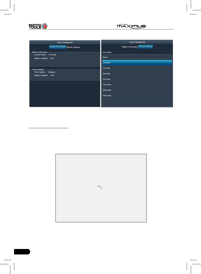
7. Power Management
This item enables you to have a general knowledge of current power information
and set standby time.
Click “Power Management”, a screen similar to Fig. 2-15 will appear.
Click “Standby Settings”, the system will enter Fig. 2-16. Click the arrow and
choose the desired standby time from the pull-down list. If MAXIMUS is only
powered by battery, you can use this option to save power and prolong the life of
your battery.
20
MAXIMUS User's Manual
Fig. 2-15 Fig. 2-16
8. Screen calibration
This option lets you calibrate the touch screen.
Click “Screen calibration”, “Please click the button to calibrate the touch screen”
will be displayed on the screen. Click the “Screen Calibration” button to enter
screen calibration interface.
Fig. 2-17
Use the stylus to click the black dot, the dot will change in red and a progress
reading will appear above it. Click and hold the dot until it proceeds to 100%,
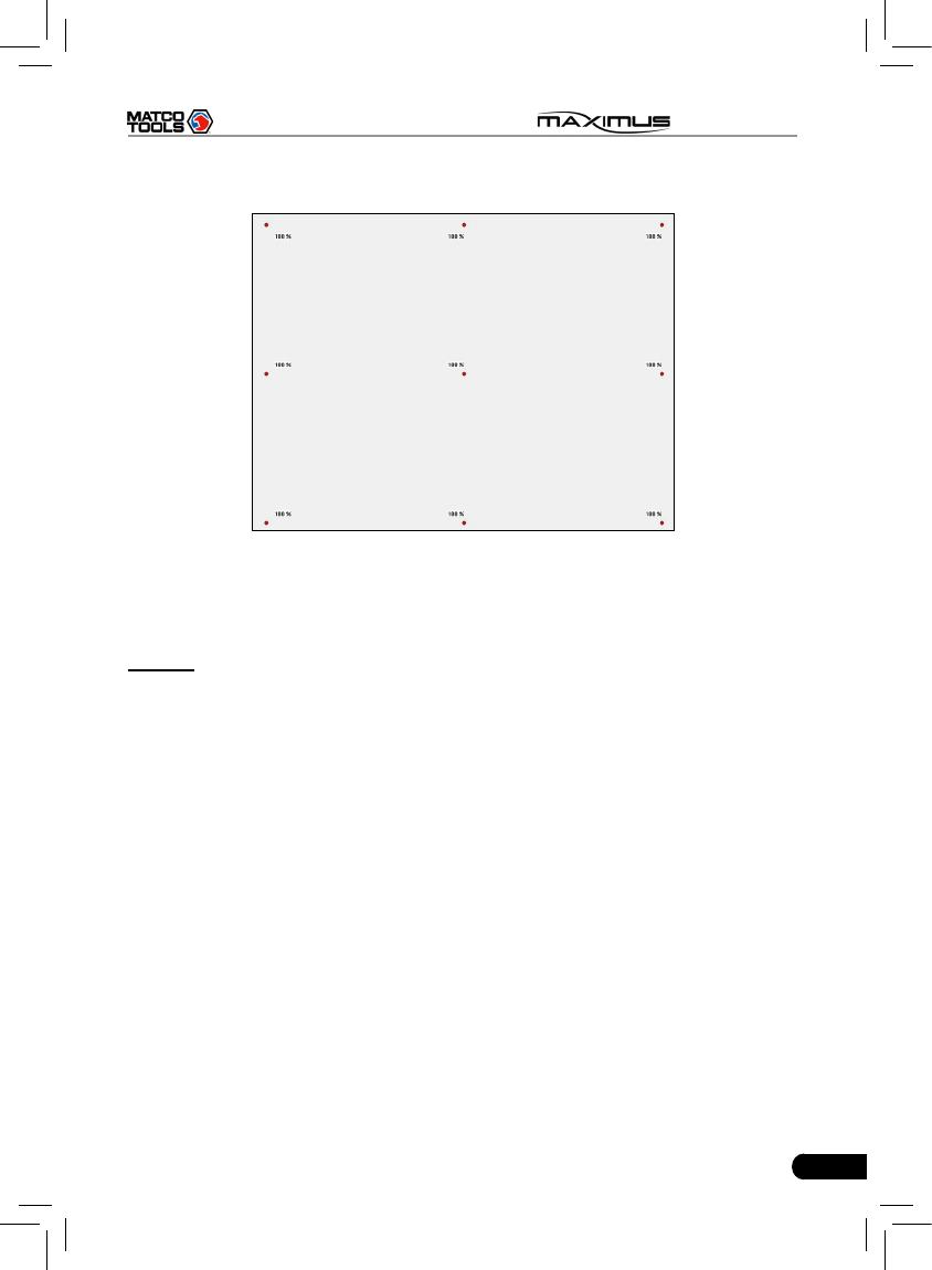
21
MAXIMUS User's Manual
then one calibration has been nished. See Fig. 2-17.
Fig. 2-18
Once all calibrations are made, the screen will display as Fig. 2-18 and the
system will return to “Settings” interface automatically.
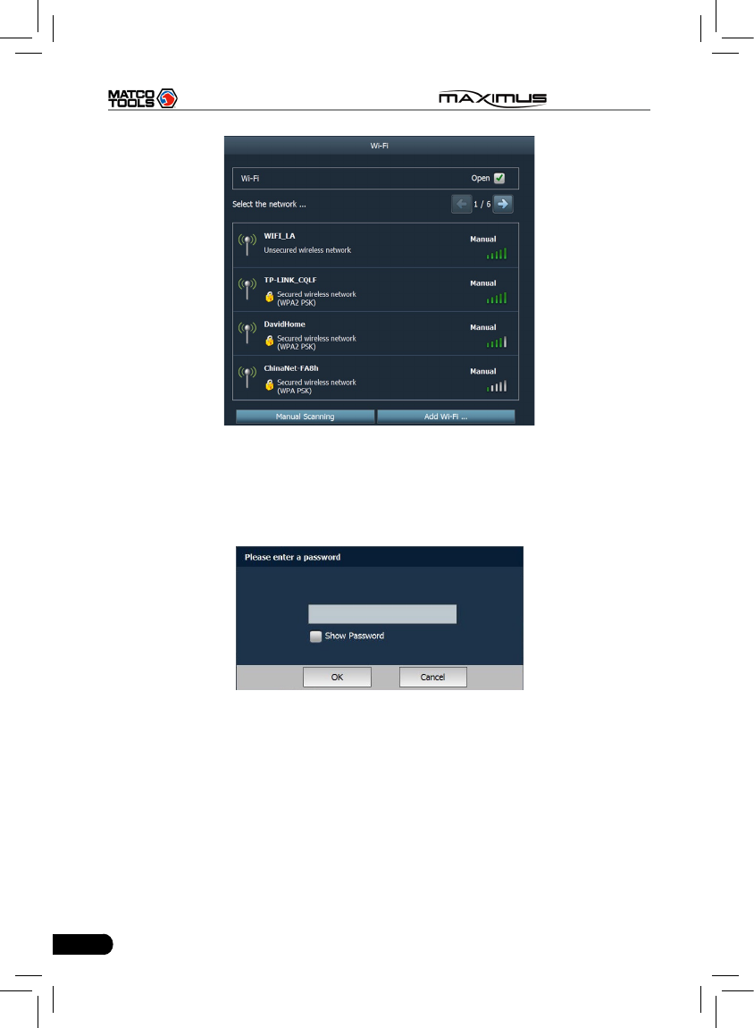
9. Wi-Fi
This option allows you to congure Wi-Fi network.
Click “Wi-Fi” and check the box next to “Close” to open it, the system will start
searching wireless network. See Fig. 2-19.
22
MAXIMUS User's Manual
Fig. 2-19
Choose one from the search result list to link. If the desired wireless router is
encrypted, you can not connect to it until correct password is keyed in. Tick off
the “Show Password” to conrm whether the password you input is correct or
not. See Fig. 2-20.
Fig. 2-20
Click “Manual Scanning” to scan manually, the screen will automatically refresh
the search result.
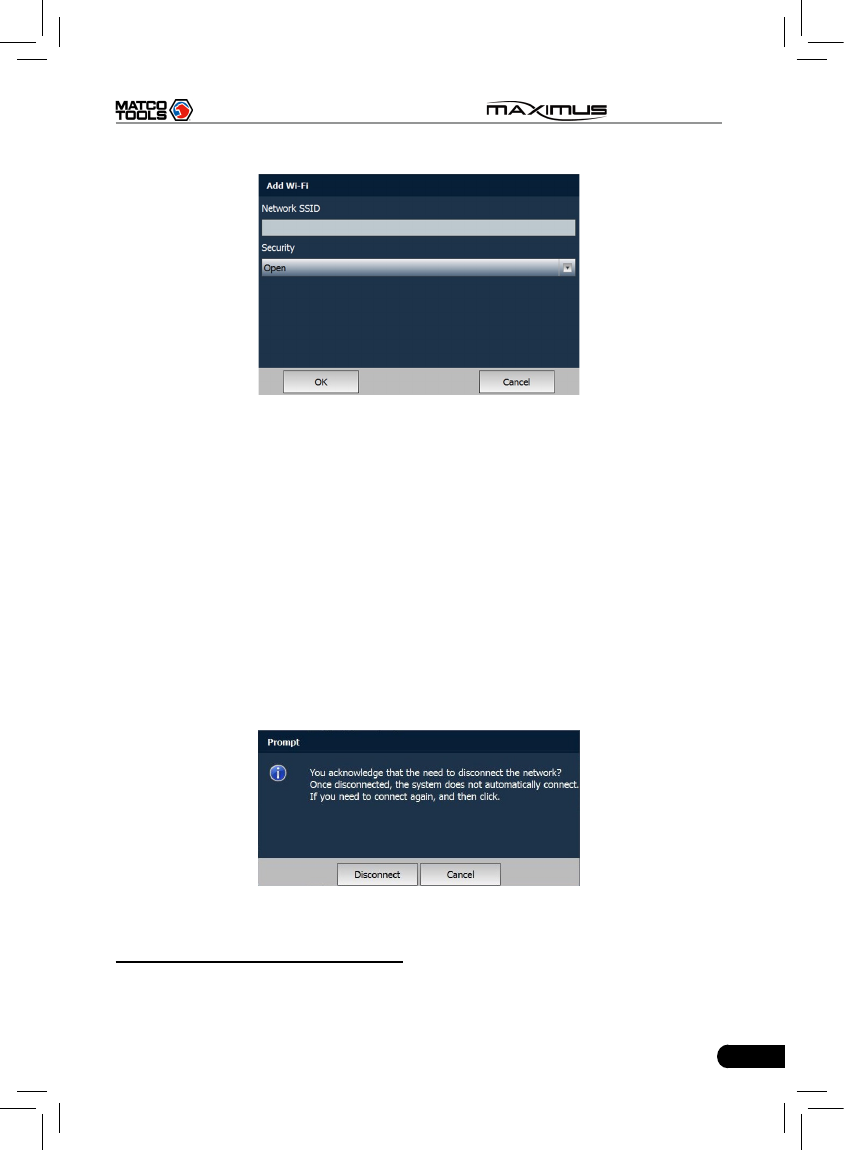
If the wireless network router to be connected is not shown in the search result,
click “Add WLAN” to add the wireless LAN. See Fig. 2-21.
23
MAXIMUS User's Manual
Fig. 2-21
Click the edit box next to Network SSID, the on-screen keyboard will appear.
Use the keyboard to input the wireless router name, and then choose one from
the security type pull-down list. Where,
Open means open network; WEP stands for unscured wireless network and
WPE/WPA2 indicates the encrypted wireless network and you have to enter the
correct password.
After inputting, click “OK” to save your setting. If “Not in the range” appears
under the added wireless network, it indicates the wireless network does not
exist or no signal can be found. In this case, please check if network SSID is
right or not or nd a place with stronger signal to retry.
To disconnect the connected network, just click it, then a prompt message as
indicated in Fig. 2-22 will appear. Click “Disconnect” to disconnect it; click “Cancel”
to abort.
Fig. 2-22
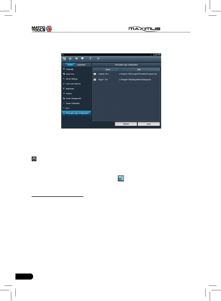
10. Third-party App Conguration
This option enables you to congure the third-party application.
Click “Third-party App Configuration”, a list of the third-party software list will
24
MAXIMUS User's Manual
be displayed on the right window. See Fig. 2-23. If no third-party softwares are
installed under Windows 7 operating system, the screen will appear blank.
Fig. 2-23
Check the desired box before the software name, then click “Save” to save your
conguration. The selected items will appear on the main menu of the diagnosis
module. Once the installed softwares are shown out of the main menu, another
icon will be appended next to the current one. Click the second to turn to next
page to browse the hidden items.
To remove it, just uncheck the box and click “Save”.
To uninstall the software, you need to click to return to Windows 7 operating
system and then enter the relative function in “Control Panel” to execute it.
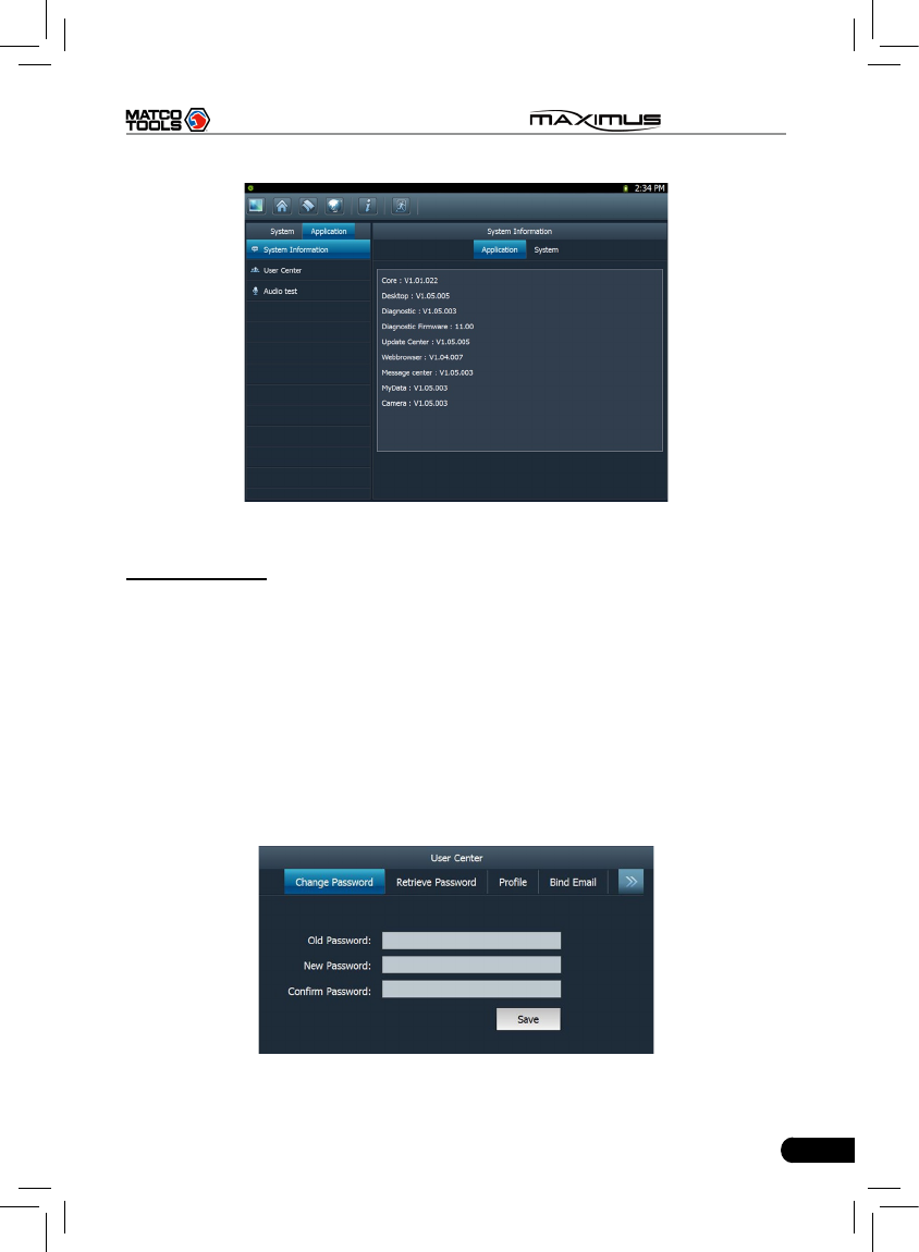
11. System information
This option enables you to view the relevant system information.
Click “System Information” under the Application tab, a dialog box prompting
“Please click the refresh button to get the system information” will pop up, click
[Refresh], a screen identical to Fig. 2-24 will appear.
25
MAXIMUS User's Manual
Fig. 2-24
12. User center
This option allows you to set the relevant user information. Since this application
is bound with Update Center, pay attention to the followings before setting this
option:
1. Make sure the MAXIMUS is properly connected to the internet. If yes, go to
Step 2.
2. On the desktop of MAXIMUS, click “Update Center”, and input CC number
and password, then tick off the box “Remember Password” and click “Login
in”. In case the box “Remember Password” is not checked, users can not
access to User center.
Click “User Center” under the Application tab, a screen identical to Fig. 2-25 will
appear.
Fig. 2-25
26
MAXIMUS User's Manual
A. Change Password
This option enables you to modify the password that you set while registering.
Input the old password and ll in “New Password” and “Conrm Password”, then
click “Save” to revise it.
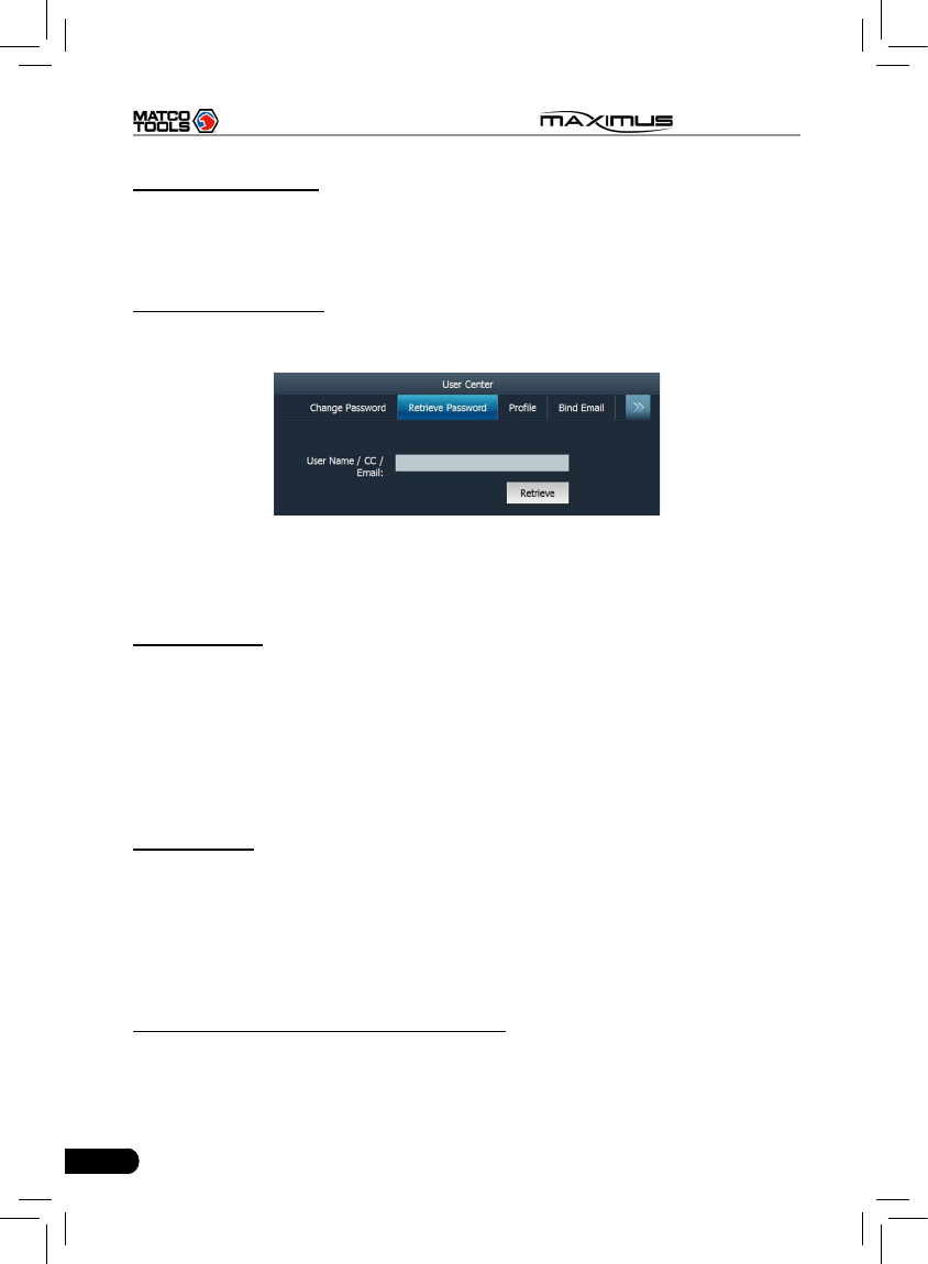
B. Retrieve Password
This option lets you take back the password if you forgot the registered
password.
Fig. 2-26
Click “Retrieve Password”, input your user name/ CC number/ E-mail, and click
“Retrieve”, the system will feedback your password to your e-mail immediately.
C. User Prole
This option is used to revise the user information that you entered while
registering.
Click “Prole”, the screen will enter prole edit window. Click the edit box, and
use the soft keyboard to input. While lling in address information, you can click
the button next to it and choose the desired one from the pull-down list. Only
country is congured can Province/State option be activated. After entering, click
“Save” to conrm and save it.
D. Bind Email
If Email is bound, we will inform you of the latest update information. It is strongly
recommeded to bind your Email. Alternatively, this option can also be set in the
process of registration. If authenticate Email is checked, the system will send the
condential information to you after you made a successful registration.
Click “Bind Email”, then click the edit box, and use the soft keyboard to input
your E-mail and other information. Click “Conrm” to bind it.
E. View product conguration information
This option is used to view product conguration information.

27
MAXIMUS User's Manual
13. Audio test
This option enables you to test the audio setting in Volume of System settings.
Click “Record” to start recording; click “Stop” to stop recording.
Click “Play” to play your recording.
28
MAXIMUS User's Manual
3 How to diagnose
3.1 Preparation and Connections
3.1.1 Preparation
Normal testing conditions1.
Turn on the vehicle power supply.•
Vehicle battery voltage range should be 9-14V and working voltage of •
MAXIMUS is 12V.
Throttle should be closed at its close position. •
Ignition timing and idle speed should be within specified range; water •
and transmission oil temperature are within normal working range (water
temperature is 90-110℃ and transmission oil temperature is 50-80℃).
Select testing connectors2.
If MAXIMUS is testing vehicles equipped with universal OBD II 16 PIN diagnostic
socket, please use the included diagnostic connector. (For vehicles with non-
OBD II 16 PIN diagnostic socket, a non-16 PIN connector is required.)
3.1.2 Connecting MAXIMUS
Follow the steps described as below to connect MAXIMUS:
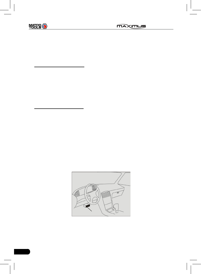
Locate vehicle’s DLC socket: it provides standard 16 pins and is generally 1.
located on driver’s side, about 12 inch away from the center of dashboard.
See the following gure. If DLC is not equipped under dashboard, an label
indicating its position will be given. In case no DLC is found, please refer to
Automobile Repair Manual.
Near the center
of dashboard
2. Plug the diagnostic connector into the vehicle’s DLC. It is suggested to use
the OBD II extension cable to connect the DLC and the diagnostic connector;
3. If you need to choose diagnosing via cable, please connect one end of the
29
MAXIMUS User's Manual
USB cable to the diagnostic connector, and other end to the USB port of
MAXIMUS. No such connections are required for bluetooth diagnosing.
4. Choose one of the two ways to obtain power from:
A. Cigarette lighter: remove the cigarette lighter, then connect one end of the
cigarette lighter cable to vehicle’s cigaratte lighter hole, and the other end
to the external power supply.
B. Power adaptor: connect one end of the included power adaptor to Power
interface of MAXIMUS, and the other end to AC outlet.
C. Battery: It stands by up to 5 hours and can keep working for 3-4 hours. If
the battery power is less than 10%, please recharge it immediately. Do the
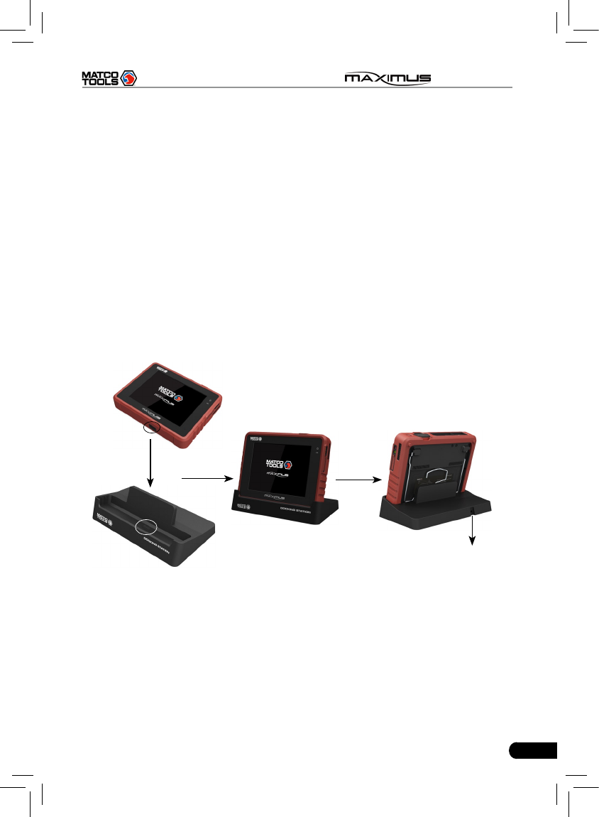
following to charge your MAXIMUS:
1. Align the charging slot on the bottom of your MAXIMUS with the slot
located at the center of the docking station, then dock it into the station
to ensure your MAXIMUS is rmly seated on the docking station.
2. Insert one end of power cord of the docking station into the power jack,
then plug the other end into the AC outlet.
To AC outlet
Note: If MAXIMUS keeps idle for a long period, please remove the battery
from it or recharge it every one or two months.
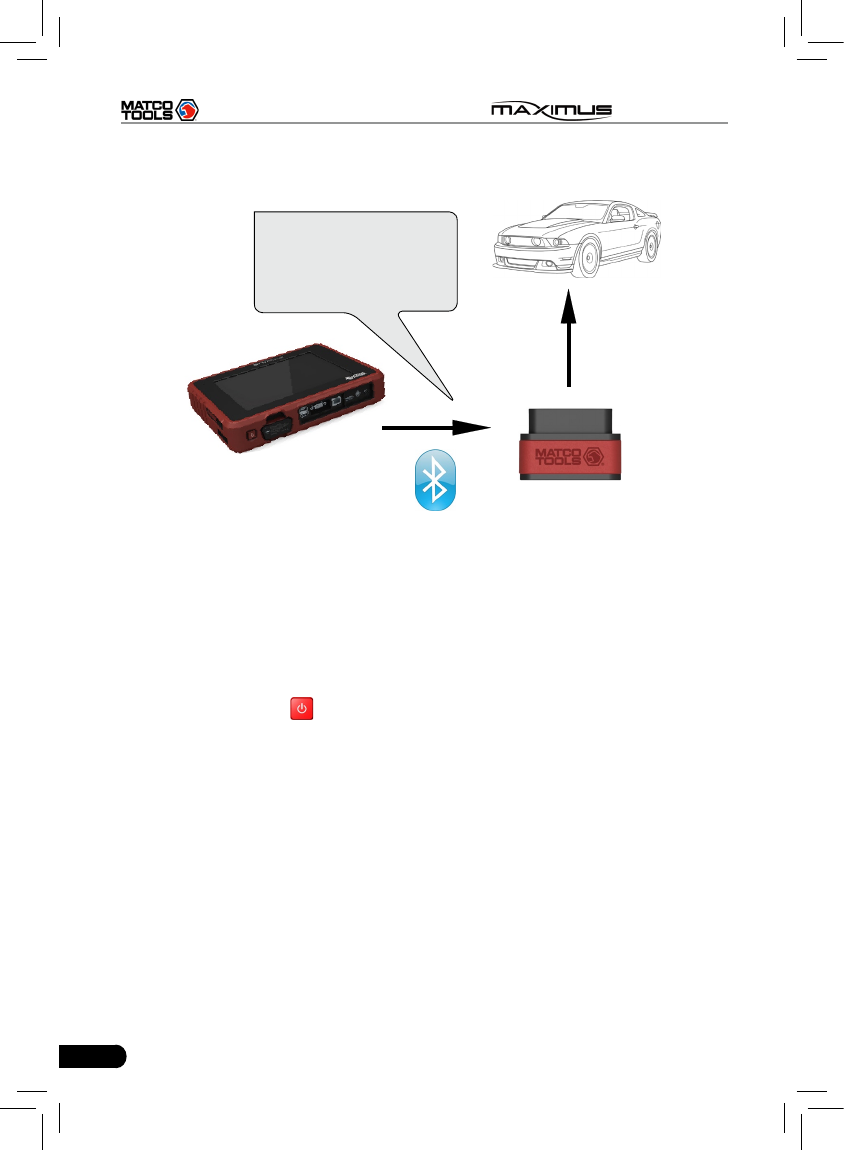
The basic working owchart is as follows:
30
MAXIMUS User's Manual
Diagnostic connector
Vehicle
Send diagnostic data to
MAXIMUS via bluetooth
or USB cable
3.2 Start diagnosing
MAXIMUS can test a lot of vehicle make, models and systems which may
continuously increase day by day. While MAXIMUS is online, the system will
remind you of new released version automatically. To keep your MAXIMUS,
please focus on prompt information and remember to download the latest
diagnostic program in time.
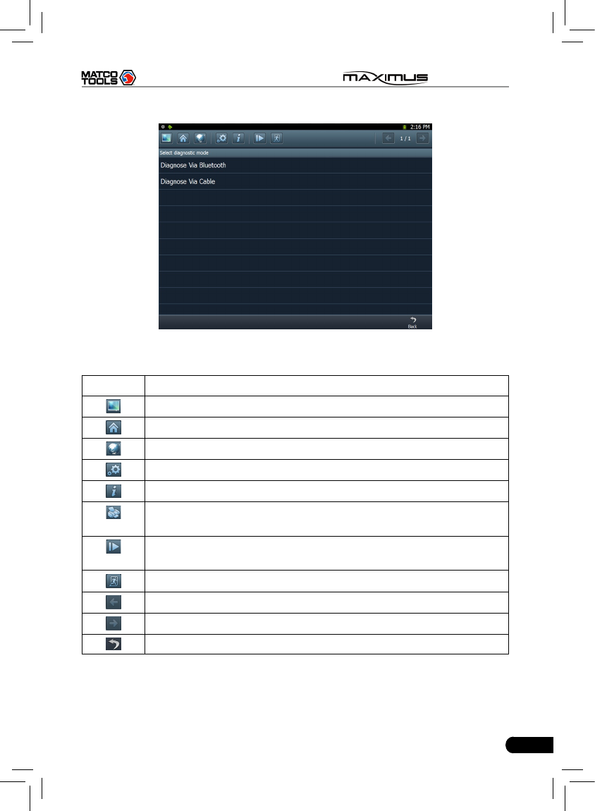
Make sure all connections are properly made (For detailed connection, please
refer to 3.1.2), press to power on and enter the main menu, and then click
“Diagnostic”, the system will enter Fig.3-1.
31
MAXIMUS User's Manual
Fig. 3-1
Descriptions for on-screen buttons:
icons Name & functions
Windows: to enter Windows 7 operating system.
Desktop: to return to the main menu.
Browser: click to open web browser.
Settings: enter system settings interface.
Module Info.: click to view the related inforation of current module.
Print: print the test result. Before printing, a printer must be
connected to the USB port of MAXIMUS via USB cable.
Manage diagnostic record: click it to enter diagnostic record
management screen. Replay and Delete are supported.
Exit system: to exit the current program.
Previous page: scroll to the previous page.
Next page: scroll to the next page.
Return: return to the previous screen.
In Fig. 3-1, choose one of the communication mothods. If Diagnose via cable is
selected, please make sure the USB cable is properly connected.
32
MAXIMUS User's Manual
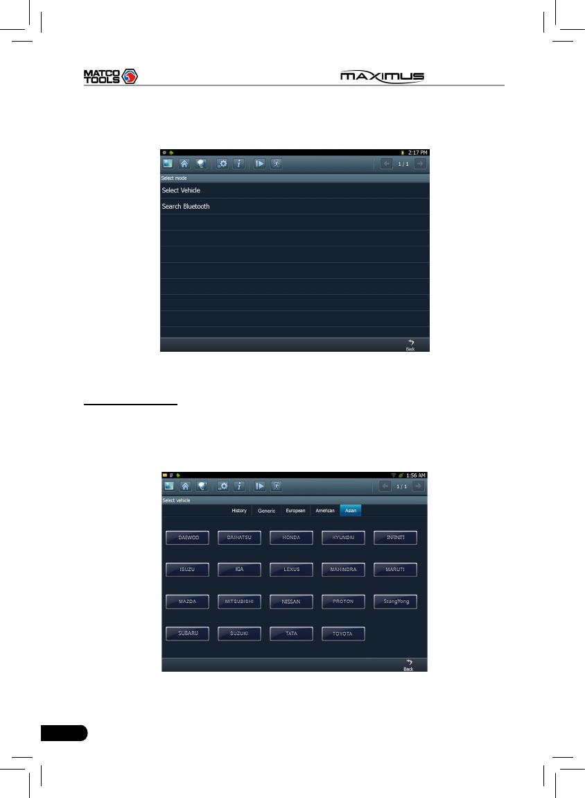
Take “Diagnose via Bluetooth” as example for demo.
Click “Diagnose via Bluetooth”, the screen will be shown as Fig. 3-2.
Fig. 3-2
A. Select Vehicle
If the diagnostic connector be paired is the one you matched last time, click this
option to enter vehicle make selection interface directly. There are 5 kinds of
options are available, namely History, Common, European, American and Asian.
Click “Asian”, the system will display all Asian vehicle makes. See Fig. 3-3.
Fig. 3-3
33
MAXIMUS User's Manual
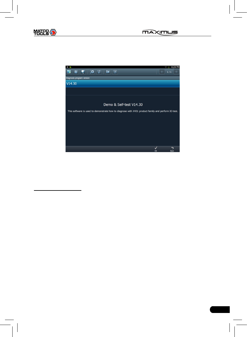
Click the desired one (for example, DEMO) in Common to enter the software
version selection screen. See Fig. 3-4.
Fig.3-4
Choose one version, and click [OK], the system starts resetting and then
validates the diagnostic connector. If ok, it will enter demo menu interface.
Choose the desired one and start diagnosing demo.
B. Search Bluetooth
This option is used to search the bluetooth device. Click it to start searching,
then choose the desired one from the result list to pair. After pairing, the system
will obtain the connector information and then go into the vehicle selection
interface directly.
Notes:
1. The bluetooth device to be paired must be the diagnostic connector
manufactured by LAUNCH, or else MAXIMUS does not work properly.
2. While diagnosing via Bluetooth, the effective communication distance between
MAXIMUS and the diagnostic connector is about 20m.
Detailed operations are as follows:
Click “Search Bluetooth” to enter Fig. 3-5.
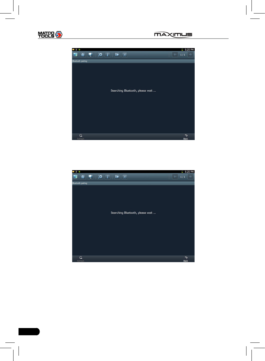
34
MAXIMUS User's Manual
Fig. 3-5
After searching, a list of bluetooth devices (Bluetooth device’s name starts with
Series No. of the diagnostic connector) will be shown on the screen. See Fig.3-6.
Fig. 3-6
Click the desired bluetooth device, the system will display “Pairing bluetooth,
please wait...”. If ok, “Pairing bluetooth succeed! Searching port, please wait...”
will be shown on the screen, otherwise, “Pairing bluetooth failed!” will appear
on the screen. Click [Back] to return to the previous screen. After linked, the
system will enter vehicle selection interface if the included diagnostic connector
is chosen.
35
MAXIMUS User's Manual
3.3 How to diagnose
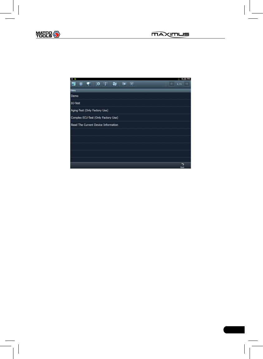
Click “DEMO” (in Common) on the vehicle selection menu, the screen will
display the main menu for DEMO diagnosis program, as shown in Fig. 3-7.
Fig. 3-7
Note: The operations for other models, series and systems are similar to “DEMO”.
Please refer to the relevant operation interface for details. Here only take the
“DEMO” for an example.
Note: Diagnosing different vehicles has the same operation steps (including the
test model, system, model year and the DLC selection options), please follow
the on-screen instructions to proceed.
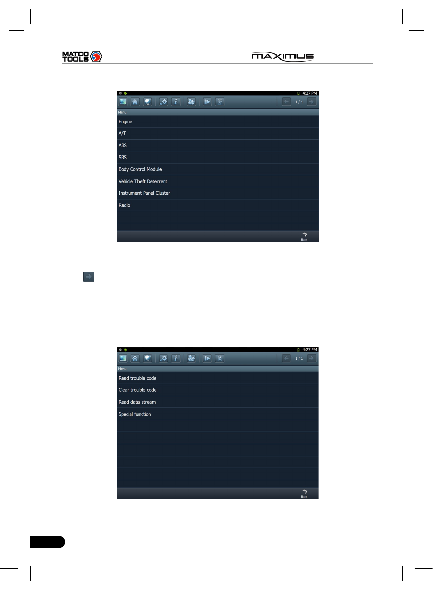
Click “DEMO”, a screen similar to Fig. 3-8 will appear.
36
MAXIMUS User's Manual
Fig. 3-8
Click [Engine] in Figure 3-8 (If there is more than one page of system menu,
click to jump to the next page), the system message “Communication is
initialized…” will appear on the screen.
Note: The test method is similar for different systems, here take [Engine] for an
example.
After communicating, the interface will skip to the function menu of [Diagnose],
as shown in Figure 3-9.
Fig. 3-9
37
MAXIMUS User's Manual
In Fig. 3-9, there are four functions of [Engine]: “Read trouble code”, “Clear
trouble code”, “Read data stream” and “Special function”.
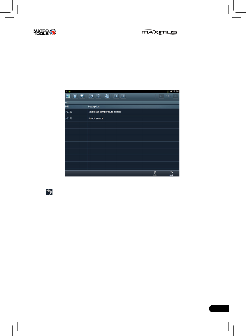
3.3.1 Read trouble code
Click [Read trouble code] in Figure 3-9, MAXIMUS starts executing this function.
After testing, results will appear on screen, as shown in Figure 3-10.
Fig.3-10
Click to return to the previous screen.
If the tested system has no DTCs, a message will appear on the screen,
indicating that there are no DTCs in the system.
3.3.2 Clear trouble code
Click [Clear trouble code] as shown in Figure 3-9, all existing trouble codes will
be cleared.
38
MAXIMUS User's Manual
Fig. 3-11
If trouble codes are cleared successfully, a prompt message will appear on the
screen, as shown in Figure 3-11. If all trouble codes have been cleared, or there
are no trouble codes, “No DTCs” will appear on the screen. Click to return to
the function menu of diagnostic system.
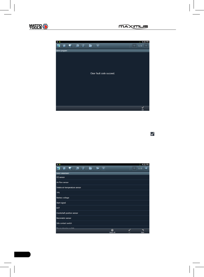
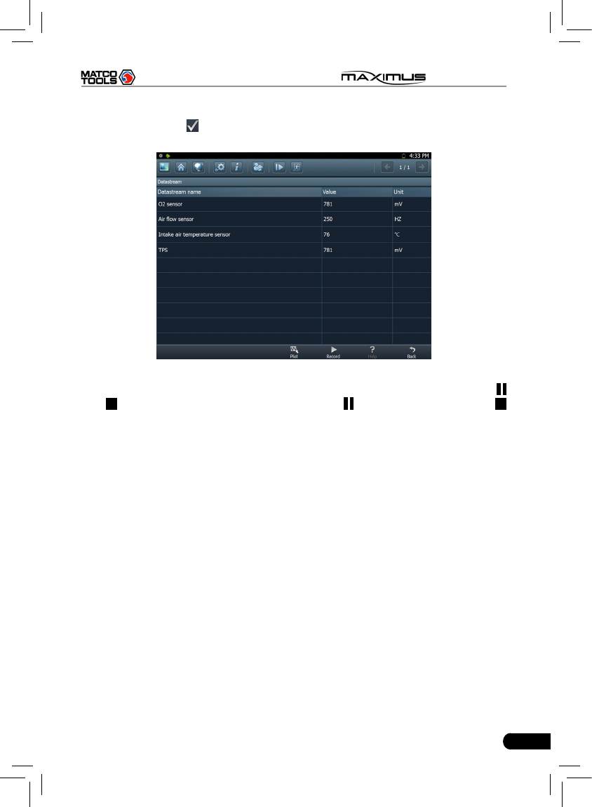
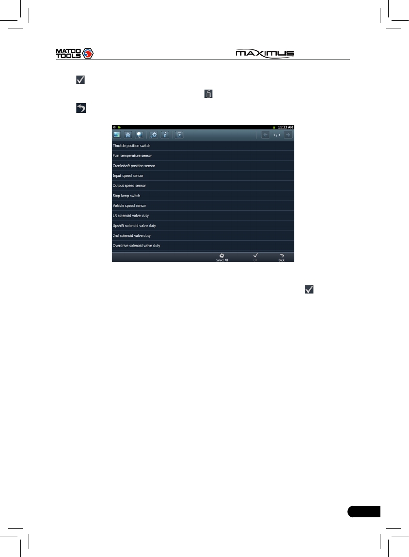
3.3.3 Read datastream
Click [Read datastream] as shown in Figure 3-9, you can read the running
parameters. See Fig. 3-12.
Fig. 3-12
39
MAXIMUS User's Manual
Click to select the desired datastream item (more datastream items can be
chosen), then click , dynamic data of the selected datastream will appear on
screen, as shown in Figure 3-13.
Fig. 3-13
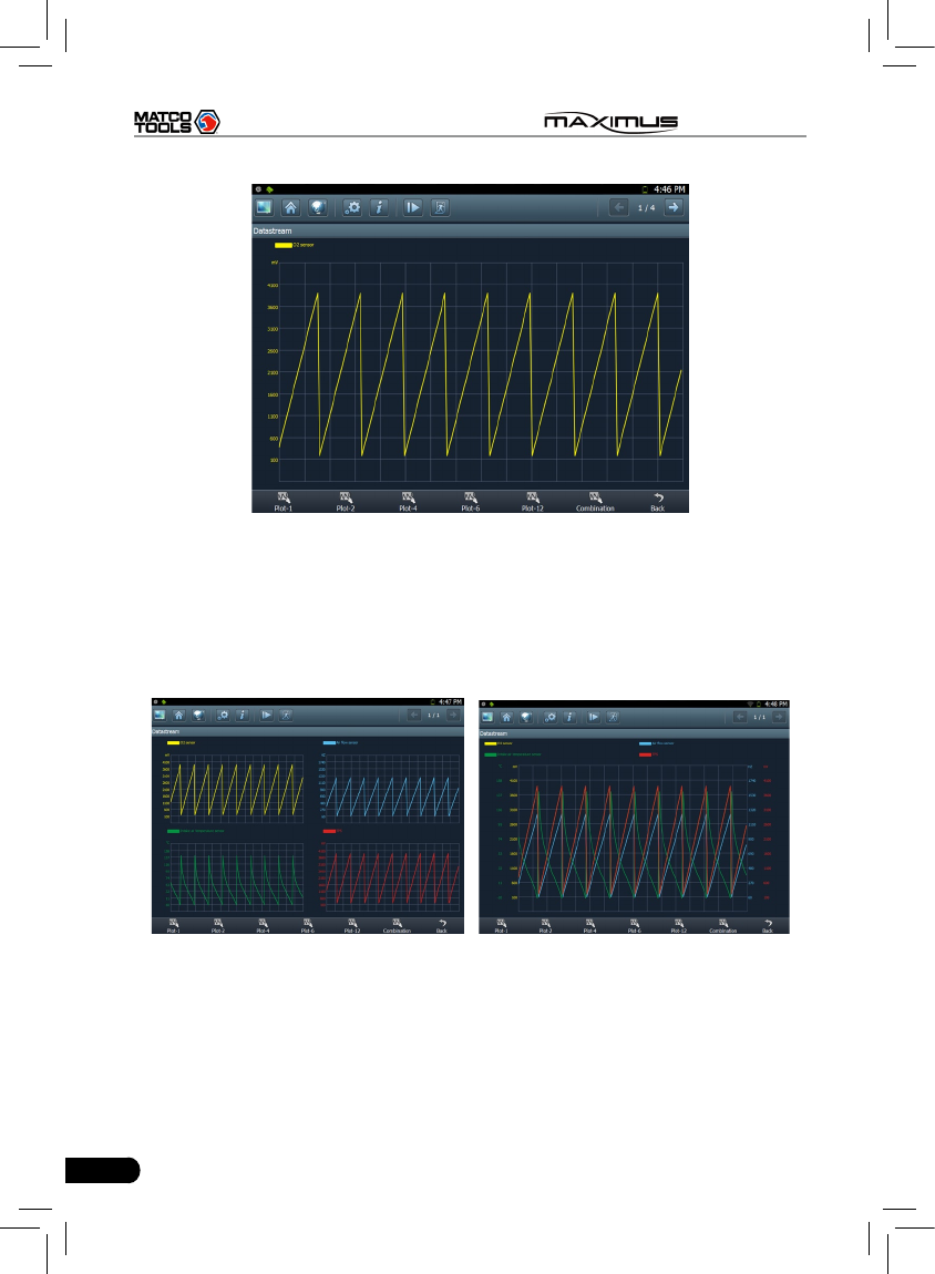
To view the dynamic waveform of the selected datastream, click [Record] (
and will become active) in Figure 3-14. Click to pause recording; click
to stop recording, and the system will automatically save the le and a message
box including the filename will pop up on the screen, where filenames follow
the rules: vehicle make + system date & time and ends with .x431, for example
BENZ-20130124163350.x431. To view the proper datastream record, please
make sure to set the accurate data and time. (For details on how to view the
recorded datastream, refer to “3.3.5 Driving record management)
Click [Plot] in Fig. 3-13, the waveform of O2 will be displayed on the screen, as
shown in Fig. 3-14.
40
MAXIMUS User's Manual
Fig. 3-14
If more datastream items are selected, click [Plot-2], [Plot-4], [Plot-6], [Plot-12]
and [Combination] to switch to display in multi-view window mode. Fig. 3-15 and
Fig. 3-16 represent the display effect of [Plot-4] and [Combination] respectively
(Combination means to display the selected datastream items into one waveform
with each datastream marking in different color for easy review and analysis).
Fig. 3-15 Fig. 3-16
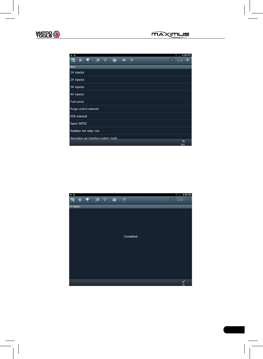
3.3.4 Special function
This option allows you to detect whether the system parameters are normal or
not.
Click [Special function] in function menu, the screen will be shown as Fig. 3-17.
41
MAXIMUS User's Manual
Fig. 3-17
Note: We just take [1# injector] as an example to show how to set the special
function.
To detect whether [1# injector] works normally or not, click [1# injector], the
screen will be shown as Fig. 3-18.
Fig. 3-18
Note: If [1# injector] works abnormally, the system will fail to indicate that the part
has some trouble.
42
MAXIMUS User's Manual
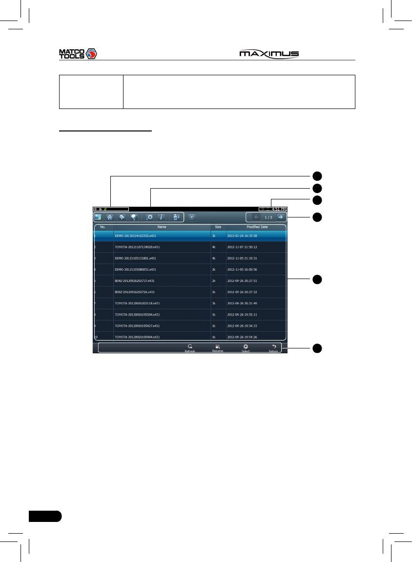
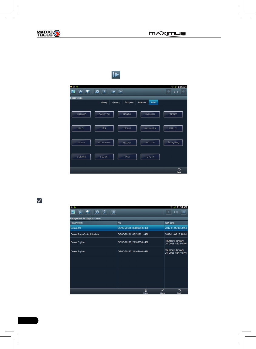
3.3.5 Driving record management
View the recorded and saved datastreams and waveforms (To record, click
[Record] on the running interface of datastreams).
On vehicle selection menu, click in Fig. 3-19.
Fig. 3-19
The system switches to Fig. 3-20, listing datastream information for different
vehicles and records in different time. Select the one you want to view and click
in Fig. 3-20.
Fig. 3-20
43
MAXIMUS User's Manual
Click , the screen will be shown as Fig. 3-21.
To delete some test system record, click .
Click to return to the previous screen.
Fig. 3-21
To view datastream information, select the desired one and click , then the
system will present you the recorded dynamic datastream information again.
44
MAXIMUS User's Manual
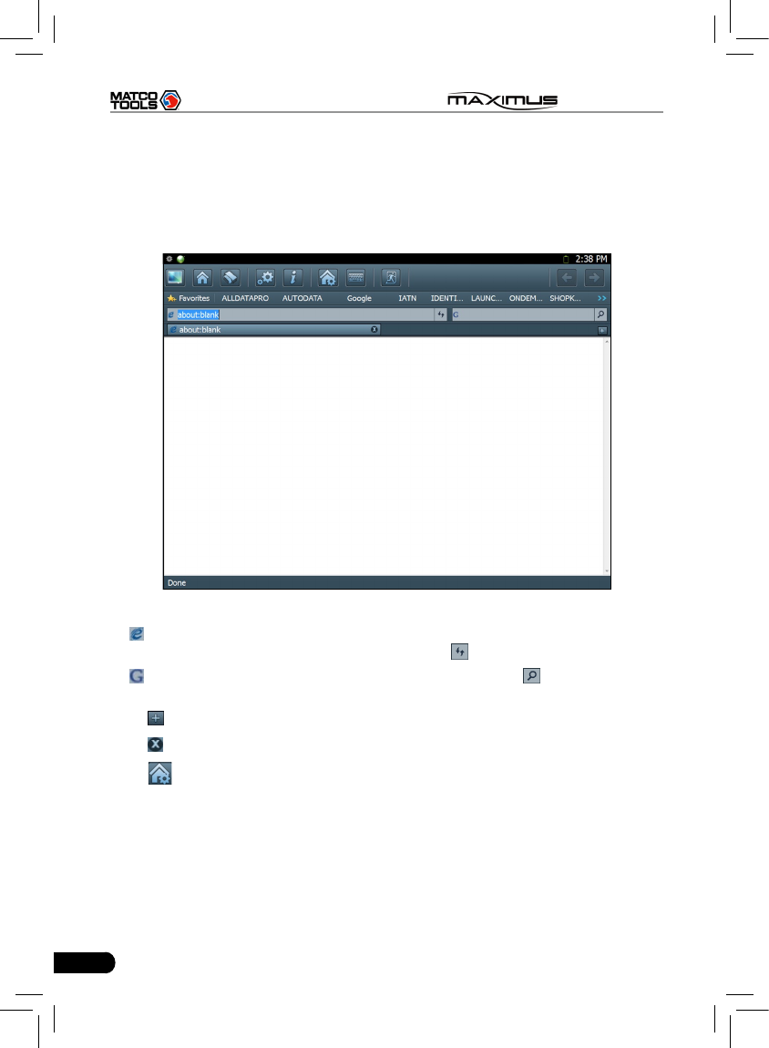
4 Webbrowser
Browser is available on MAXIMUS, which helps you retrieve and search for
information sources all the time.
Click [Webbrowser] to enter.
Fig. 4-1
In address bar, use the on-screen keyboard to input the Uniform Resource
Identier (URL) of the desired resource, and click to visit it. See Fig. 4-1.
In search bar, input the desired information and click to search it with
google search engine.
Click to open a new blank page.
Click to close the page.
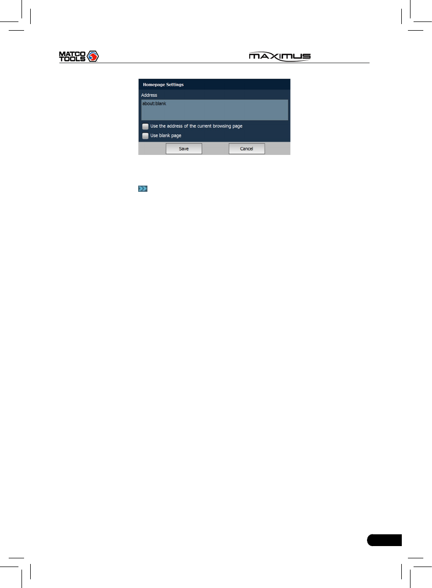
Click , a dialog box similar to Fig. 4-2 will appear on the screen.
Check the box “Use the address of the current browsing page” and click “Save”,
the system will set the current web page as the homepage. Next time you launch
the browser, it will open the homepage link by default. If “Use blank page” is
checked , homepage will be configured as a blank page and the browser will
display a blank page once you open the browser.
Note: Only one homepage can be set.
45
MAXIMUS User's Manual
Fig. 4-2
Click Favorites to bookmark the web pages so that the user can quickly return to
them in future. Click to view and maintain the favorites.
46
MAXIMUS User's Manual
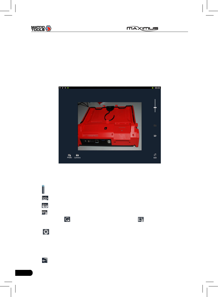
5 Camera
MAXIMUS is equipped with a 1.3 mega pixel lens for your photographing and
video recording. Pictures are taken in .jpg format and videos are recorded in .avi
format. All pictures and videos are saved in relevant module folder in “My Data”
where users can browse and replay it.
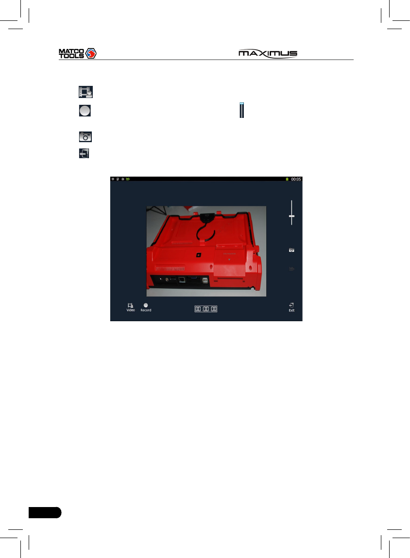
Click [Camera], the screen will enter video recording interface as shown in Fig.
5-1.
Fig. 5-1
In Camera mode,
Drag scroll bar to adjust the screen size.
Click to switch to video mode. See Fig. 5-4.
Click to take a picture.
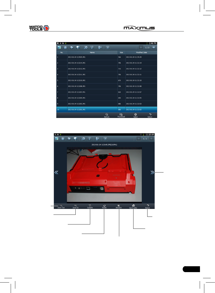
Click to view all photos that has been already taken. See Fig. 5-2.
In Fig. 5-2, click to refresh the current page. Click to switch to thumbnail
mode. click the desired one in thumbnail mode to open it. See Fig. 5-3.
Click , a checkbox will appear before each image file, click “Select all” to
choose all les or check the desired box to select les as desired. To deselect it,
click “Cancel Selection”. Once les are selected, click “Delete” to remove it; click
“Export” to export it to U-disk (To perform export, a USB storage device must be
inserted).
Click to exit the program.
47
MAXIMUS User's Manual
Fig. 5-2
View next
picture
Adjust picture to
the suitable size
Zoom in
Zoom out
Send the picture
out via email
Return to the
previous screen
Rename the picture
Rotate the picture
Fig. 5-3
48
MAXIMUS User's Manual
In Video mode,
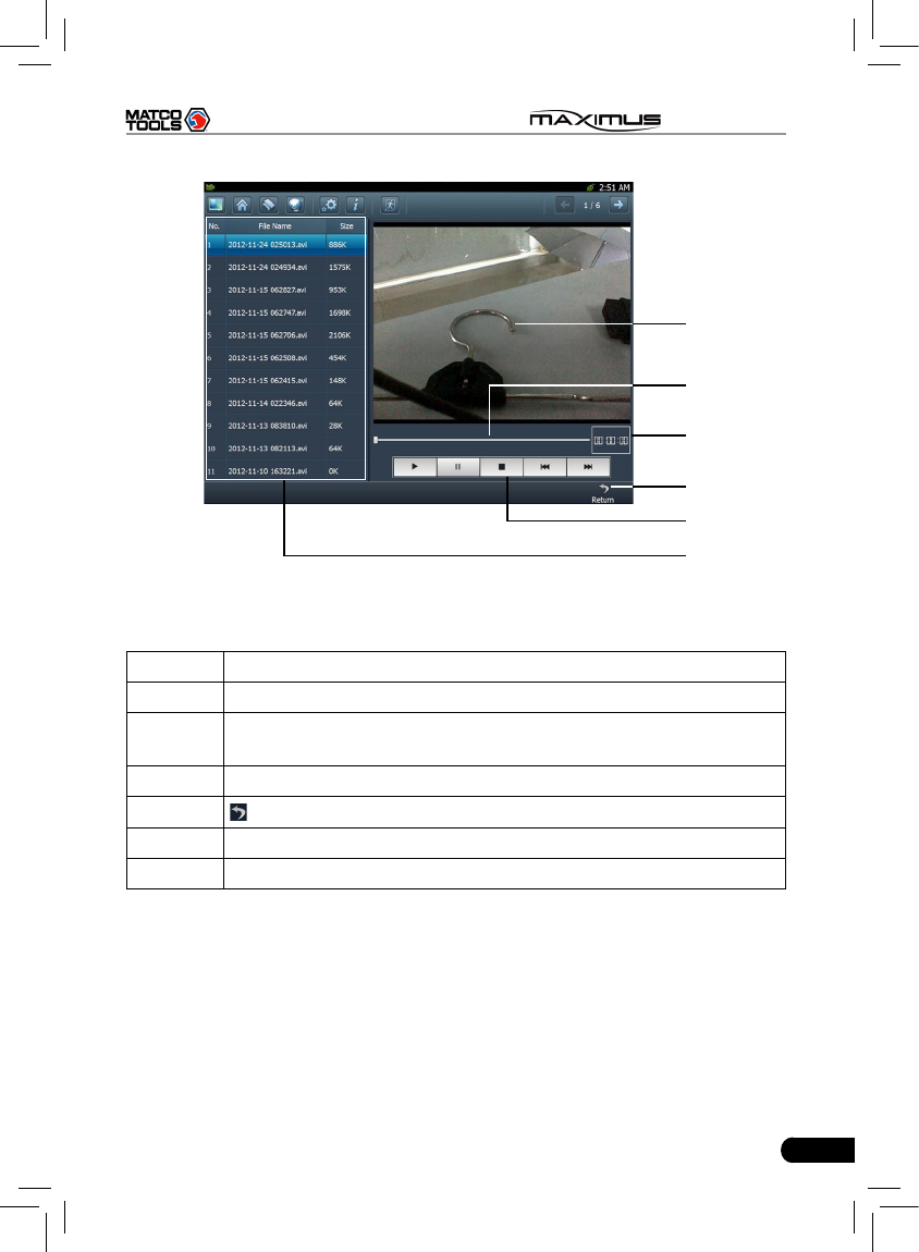
Click to view all recorded video les. See Fig. 5-5.
Click to start recording. While recording, drag scroll bar to adjust the screen
size.
Click to switch to camera mode.
Click to exit the program.
Fig. 5-4
49
MAXIMUS User's Manual
A
B
C
D
E
F
Fig. 5-5
Below are detailed descriptions on layout and functions on Fig. 5-4.
Icon Name & Functions
APlayback window
BPlayback progress bar: drag it directly to perform fast forward/fast
reverse function.
CPlayback time
D Return: return to the previous screen.
EPlayback control buttons: controls the progress of playback.
FVideo le name display area
50
MAXIMUS User's Manual
6 Message Center
MAXIMUS provides message center function, by which you can send E-mail to
us once you come across any question or problem unresolved, and we will give
you professional answer in time.
To use this function, make sure that you have registered your product
successfully and network is properly congured.
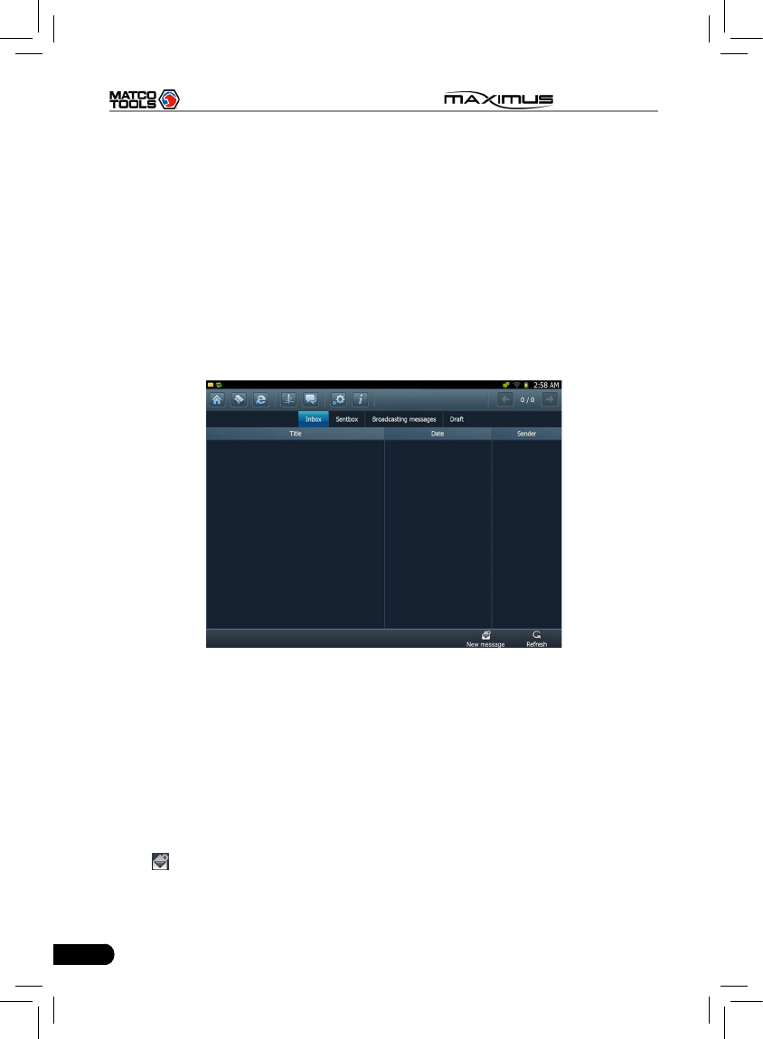
6.1 Read message
Click [Message Center] on the main menu, the system will enter a screen similar
to Fig. 6-1.
Fig. 6-1
Input your user name/CC/Email, then click [Log In] to enter the message center
main menu. If you have not registered your product, please click [New Register]
to start registering. For details on how to register, please refer to item 8.1
Register in Chapter 8 Update.
In mailbox interface, there are four items available: Inbox, Sentbox, Broadcasting
messages and Draft. Select one, and click it to read the details.
6.2 New message
Click [ ] on the message center main menu screen, message writing interface
appears on the screen.
51
MAXIMUS User's Manual
Click title or content edit box, the on-screen keyboard will appear automatically,
use it to input or write down the title and contents by stylus manually.
Button descriptions:
[Attachment]: click to add an attachment.
[]: send the message.
[]: save a message that is not nished or will be sent later.
[]: return to the previous screen.
When a new message is nished, click [ ] to send.
If the message is sent out successfully, a prompt message will pop up. If the
message fails to send out, a dialog box will appear on the screen. Click [OK] to
send it again, or click [Cancel] to cancel sending.
52
MAXIMUS User's Manual
7 J2534 Toolbox
Flash programming has become a common and profitable procedure in the
repair and service of today’s vehicles. As part of the 21st Century Tune-up,
reprogramming is often the only solution for problems ranging from driveability
and loss of power to poor fuel economy and emissions related issues. J2534box
makes it easy. The J2534box is a communication interface designed to support
J2534 specications for ECU reprogramming and pass-thru diagnostics, while
J2534 Toolbox is a helper program to guide you through reprogramming and
performing after-ash routines.
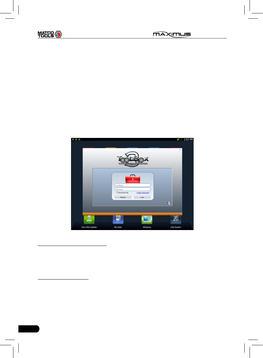
Make sure JBOX(hardware device name) is properly connected, and then click
“J2534 Toolbox 3” on the desktop, the system starts up and then enter the login
interface as indicated in Fig. 7-1.
Fig. 7-1
If you have been a member, input your user name and password, then click
"Login" to enter. To avoid repeated input, check the box “Remember Me” and
the system will save your information. Next time you launch this program, the
screen will keep your data as it is. In case you forgot your password, click “Forgot
Password” to nd back your password.
If you are a new user, click “Register” to enter registration page, then follow the
on-screen instructions to nish your registration.
For detailed operations on J2534 Toolbox 3, please refer to the user’s manual of
JBOX.
53
MAXIMUS User's Manual
8 Update
MAXIMUS provides quick and easy software update service, by which you can
enjoy all update services including download and update the software.
Note: Enter the update center, vehicle software which can be updated are
default to be checked, you can click [Upgrade] to perform one-key update. You
can also click [Opt] to select all or deselect all.
8.1 Register
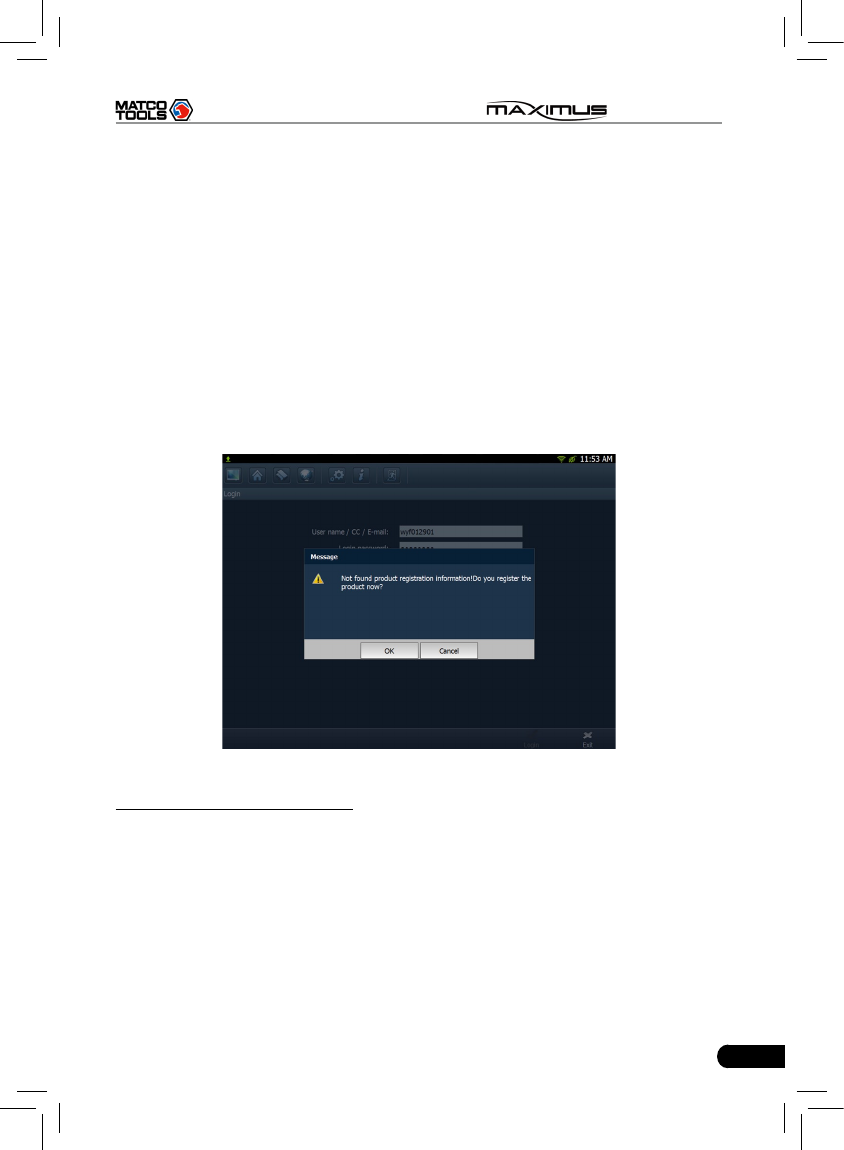
8.1.1 Register your information
To operate this device, you have to experience a product registration. After
entering the function module, a screen similar to Fig. 8-1 will appear.
Fig. 8-1
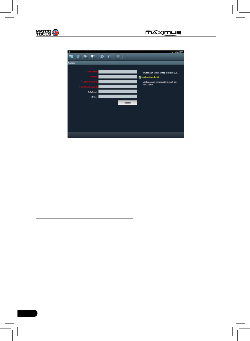
A. In case you are a new user
Click [OK] to read service terms. After reading all items, click [Agree], a
registration page as indicated in Fig. 8-2 will appear automatically. Once
registering is complete, this page will never appear again.
54
MAXIMUS User's Manual
Fig. 8-2
Note: Before registering, please check you network configuration or Wi-Fi
connection.
After you registered successfully, the system will feedback a prompt message
to you. If “Authenticate Email” is checked while registering, the system will also
prompt you that you have bound Email successfully.
Note: If Authenticate Email is checked while registering Email information, the
system will send the confidential information to your Email immediately after
registering successfully. And we will notify you of the latest update information in
the future. It is strongly suggested to bind with your Email.
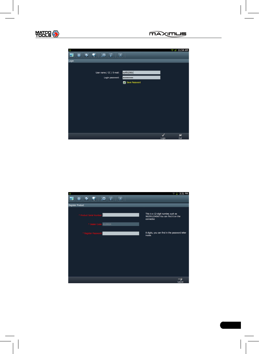
B. If you have registered to be a member
In this case, the system will enter the login interface as shown in Fig. 8-3.
55
MAXIMUS User's Manual
Fig. 8-3
Click [Login] to enter update center.
8.1.2 Register your product
After registering your personal information, the screen will enter the product
registration page.
Fig. 8-4
Product SN is printed on the bottom of MAXIMUS. While purchasing this product,
you will be offered one envelop, in which there is the registration password
56
MAXIMUS User's Manual
(secret). Complete lling the information and click [Submit] to proceed to the next
step. After registering your product, the system will enter update center.
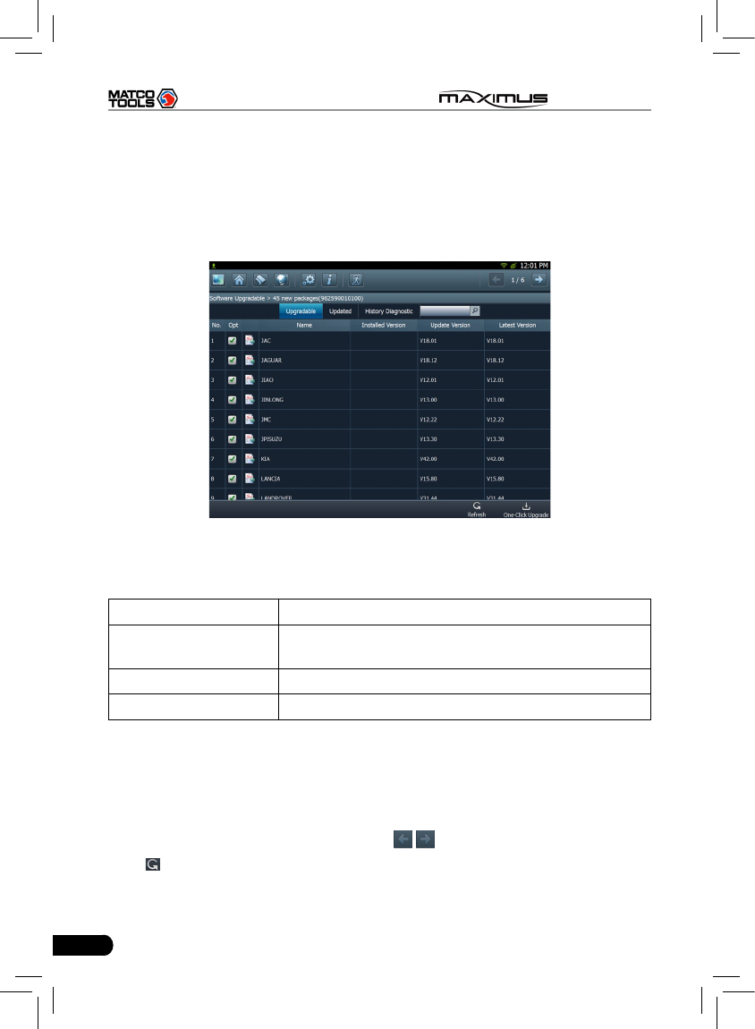
8.2 Update
While updating, make sure your network (wired or Wi-Fi) works properly, then
click “One-click Update” to enter Fig. 8-5.
Fig. 8-5
In Fig. 8-5, there are 3 options: Upgradable, Updated and History Diagnostic.
For details, please refer to the table as below:
Option Functions
Upgradable View all upgradable softwares including main unit
software and diagnostic software
Updated View all updated softwares
History Diagnostic Update diagnostic software of certain vehicle make
If a upgradable version is available for certain software, the checkbox close to it
will be selected by default.
By default, all software items are selected.
Click “Opt” in title bar to deselect all or select all.
If the content is more than one page, click / to turn pages.
Click to refresh the page.
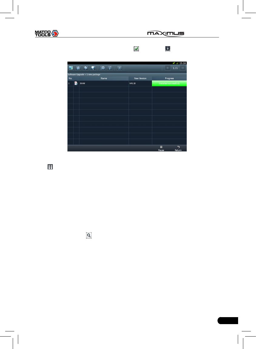
To select certain items, click “Opt” to deselect the checked mark, then click the
57
MAXIMUS User's Manual
desired item, the checkbox will become to , then click , the system will start
downloading, as shown on Fig. 8-6.
Fig. 8-6
Click to pause the download.
After download finishes, the system will install the softwar automatically. If
“Installation succeed” appears, it indicates that installation has completed.
If the network communication interrupts, software download will fail and
“Installation failed” will be shown. In this case, please check the network and
download it again.
If “Install after restart” appears, this software will be installed automatically after
restarting system.
Additionally, vehicle search is also supported. Input the desired vehicle make in
search box, and click , all search result will be listed on the screen. Click the
desired one to update.
58
MAXIMUS User's Manual
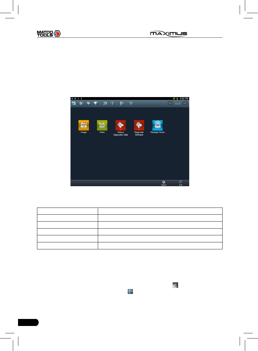
9 My data
This option enables you to manage user data, including diagnostic data log,
photos, videos. Moreover, you can perform browse, view, clear, and export etc.
Data export is supported on all other options except Diagnostic software.
In main menu of MAXIMUS, click [My data], the screen will be displayed as Fig.
9-1.
Fig. 9-1
For details, please see the following Table 9-1.
Options Descriptions
Image Saves all photographing les.
Video Saves all video les which users use Video to record.
History Diagnostic Data View and play back the history diagnostic data.
Diagnostic Software Keeps all diagnostic softwares you ever applied.
Message Center All received pictures from letterbox are kept in it.
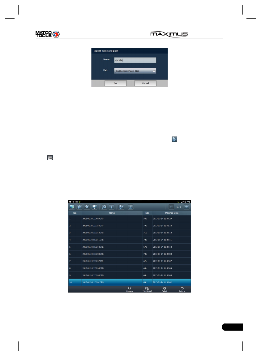
9.1 Export data
To export all data saved in My Data successfully, please be sure that the USB
device has been inserted into the USB port of MAXIMUS. Click “Select” on the
bottom of the screen, a check box will appear on upper right corner of each
option, tick the box(except Diagnostic Software), and click to export it to USB
device. Alternatively, you can also click on the shortcut bar to export it.
Note: Before performing export operation, you have to select the items you want
to export.
59
MAXIMUS User's Manual
Fig. 9-2
Click in the Name edit eld, then the on-screen keyboard will appear. Input the
desired name. Click the triangle and choose the destination path from the pull-
down list.
9.2 Import data
To import data from USB device into the MAXIMUS, click on the shortcut bar
to export it. A import path dialog box will pop up, choose the desired path and
click “OK”. A list of les will be listed on the screen, highlight the desired one and
click to import it.
9.3 Operations in Image & Video & Message Center
Since the operations of Image is identical to Video, Message Center, here we
just take “Image” for example.
In Fig. 9-1, click “Image” to enter the following screen.
Fig. 9-3
60
MAXIMUS User's Manual
Button Descriptions:
Buttons Descriptions
Refresh Refresh the current screen.
List Arrange the les by list.
Thumbnail Arrange the les in thumbnail mode.
Select
To select the itmes.
Select all Select all items.
Delete Delete the selected items.
Export Export the select items.
Cancel Selection Deselect the selected items.
Return Return to the previous screen.
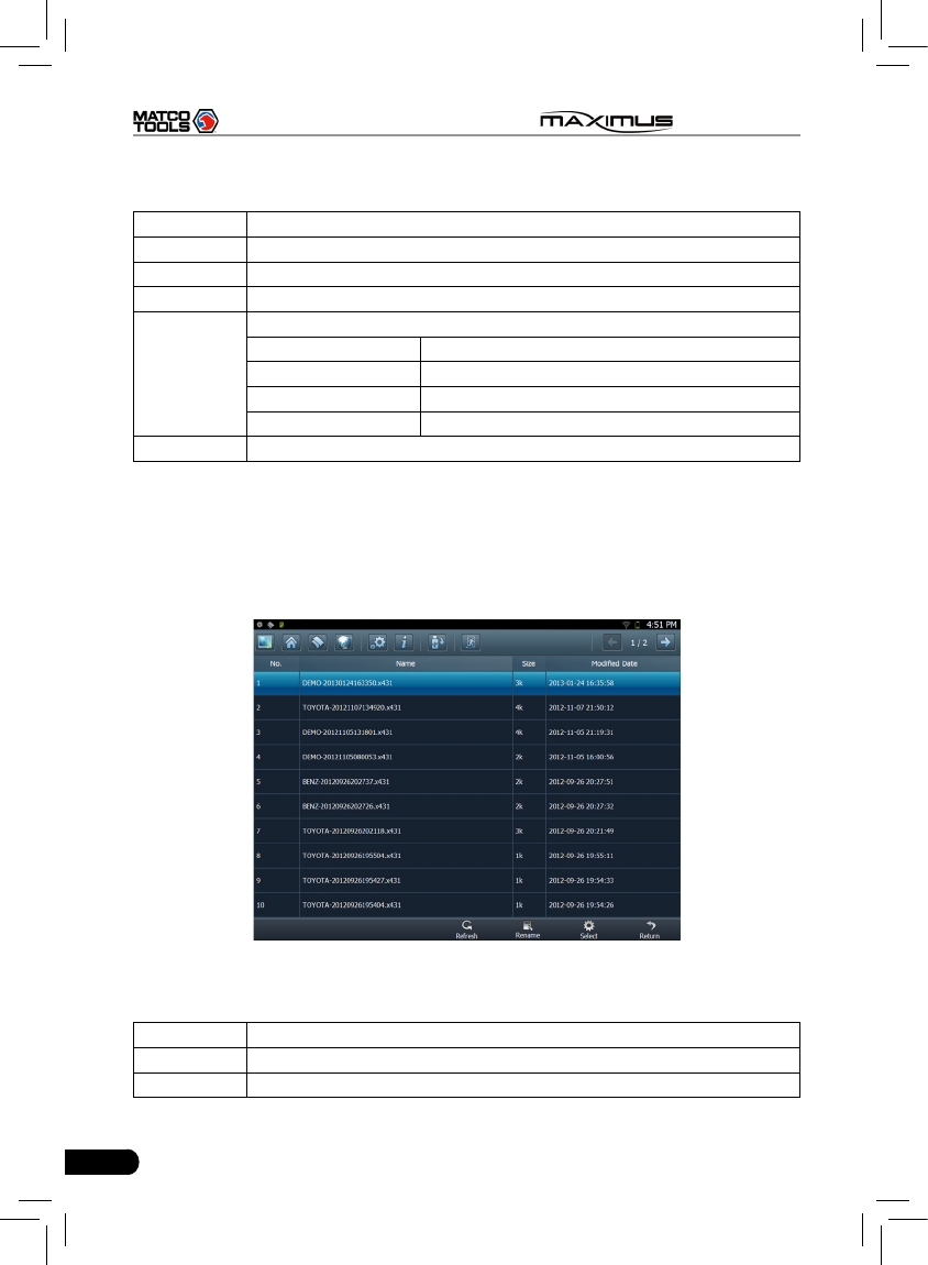
9.4 Review history diagnostic data
Click “History Diagnostic Data” to enter the screen. (To generate the history
diagnostic data le, you have to record some datastream while diagnosing. For
details, please refer to “3.3.3 Read datastream”.)
Fig. 9-4
Button Descriptions:
Buttons Descriptions
Refresh Refresh the current screen.
Rename Rename the highlighted datastream.
61
MAXIMUS User's Manual
Select
To select the itmes.
Select all Select all items.
Delete Delete the selected items.
Export Export the select items.
Cancel Selection Deselect the selected items.
Return Return to the previous screen.
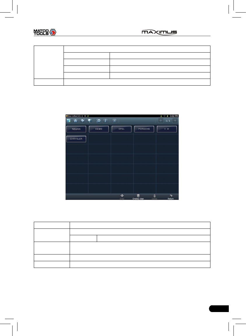
9.5 Clear Diagnostic software
Click “Diagnostic Software”, a screen similar to Fig. 9-5 will appear:
Fig. 9-5
Button Descriptions:
Buttons Descriptions
Enter Enter the selected diagnostic software.
Clear Clear the selected software version.
Onekey Clear Delete all other history versions of each vehicle except the two
latest versions.
Delete Deleter the selected software.
Return Return to the previous screen.

62
MAXIMUS User's Manual
10 FAQ
In process of operation of MAXIMUS, you may come across some questions,
including the software, hardware, operation and something related to the
vehicles. Read the user’s manual to get the answer if you have any question. If
it can not be solved still, please note it down and contact our Customer Service
Center for help.
Here, we list some frequently asked questions and answers on using MAXIMUS.
10.1 About hardware
Q: Why does the LCD touch screen respond so slowly in cold whether?
A: It is because the ambient temperature is close to the lower limit of operating
temperature range (-10-55℃). Under this situation, it is necessary to warm up
the machine for 30 minutes before test.
Q: There is only backlight and no character on the screen. What should I
do?
A: Check if the power is well connected. Turn off the machine, unplug the power
connector and re-plug it. Turn on the machine after it has been connected to
the power for 1 second.
Q: Why there is no response or response incorrectly while clicking the
screen with touch pen?
A: Please calibrate the screen again.
Q: What can I do when the screen is confused?
A: Please quit the current application (interface), and run it again. If the problem
still exists, please restart the system.
Q: Why can’t the data be input after Soft Keyboard is activated?
A: The position where the cursor locates can’t be edited. Or you have not
activated the cursor in the input position, please use the stylus to click the
part to edit. You can input the data if the cursor ashes.
10.2 About software
Q: System halts when reading data stream. What is the reason?
A: It may be caused by a slackened connector. Please turn off the machine,
rmly connect the connector, and switch on the machine again.

63
MAXIMUS User's Manual
Q: Why MAXIMUS fails in communication with ECU?
A: ECU does not respond. Please try to use the latest update tool to upgrade to
the latest diagnostic program.
10.3 About system
Q: Main screen blinks at the moment when engine ignition.
A: It results from electromagnetic interference and this is normal phenomena.
Q:Diagnose interrupted during diagnosing process.
A: Caused by electromagnetic disturbing or poor connecting.
Q: There is no response when communicating with on-board computer.
A: Please conrm the proper voltage of power supply and check if the throttle
has been closed, the transmission is in the neutral position, and the water is
in proper temperature.
Q: The systems equipped with the vehicle can not be diagnosed.
A: DLC of some early models is separated; refer to User’s Manual for details.
Q: The fault code storage is blank.
A: Usually, it’s the “suquela” for shared circuit. Please locate and analyze the
most similar fault code and its circuit.
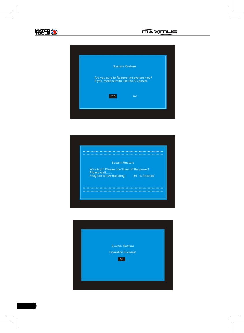
10.4 System Recovery
Q: Software runs improperly.
A: Solution: Try to use the one-key recovery to restore MAXIMUS to the default
settings. System recovery does not affect any data (including the downloaded
diagnostic software) that users saved before. Follow the steps described as
below to proceed system recovery:
1. Disconnect all devices from MAXIMUS and turn it off.
2. Use the included power adaptor to supply power to MAXIMUS.
3. Insert an external USB keyboard into the USB port of MAXIMUS.
4. Press [POWER] button on MAXIMUS, then press and hold F12 on the
keyboard until the system enters recovery mode:
64
MAXIMUS User's Manual
5. Press ENTER to start recovering, and the screen will be shown as follows
(Warning: Please DO NOT turn off the power while recovering!):
6. Ater recovery is complete, a screen similar to the following gure will appear:

65
MAXIMUS User's Manual
7. Press --> to restart your MAXIMUS.
Note: After system recovery is complete, users need to connect MAXIMUS to
internet and update it to the latest software version.
10.5 Other questions
Q: How long is the standby time of battery?
A: Recharge it correctly. In general, the charging time is about 6 hours for new
machine. Once the charing icon disappears, it indicates it is fully charged. If
standby time is set, it can last for about 7 hours.
Q: The screen is too white and characters cannot be seen. What is the
reason and what should I do?
A: It may be caused by improper contrast. Please refer to the section “Adjust
Brightness” to adjust the contrast.
Q: Why is the machine automatically powered off during standby?
A: It is because the machine has been set for energy saving. Automatic
shutdown will take place if the machine is not operated for a specied period
of time. Refer to the section “Power option” under System setting in User’s
Manual.

66
MAXIMUS User's Manual
Customer Service Department
If you have any questions on the operation of the unit, please contact us: 1-877-
LAUNCH-9
Statement: LAUNCH reserves the rights to make any change to product designs
and specications without notice. The actual object may differ a little from the
descriptions in the manual in physical appearance, color and configuration.
We have tried our best to make the descriptions and illustrations in the manual
as accurate as possible, and defects are inevitable, if you have any question,
please contact local dealer or after-sale service center of LAUNCH, LAUNCH
does not bear any responsibility arising from misunderstandings.