Launch Tech MAX2 Automotive Diagnosis Computer User Manual MAXIMUS2 0 English add share indd
Launch Tech Co., Ltd. Automotive Diagnosis Computer MAXIMUS2 0 English add share indd
Users Manual
Version: V1.00.000
Revised date: 02-10-2014

II
MAXIMUS2.0 User's Manual
Copyright Information
Copyright © 2013 by LAUNCH TECH. CO., LTD. All rights reserved.
No part of this publication may be reproduced, stored in a retrieval
system, or transmitted in any form or by any means, electronic,
mechanical, photocopying, recording or otherwise, without the prior
written permission of LAUNCH. The information contained herein is
designed only for the use of this unit. LAUNCH is not responsible for
any use of this information as applied to other units.
Neither LAUNCH nor its affiliates shall be liable to the purchaser
of this unit or third parties for damages, losses, costs, or expenses
incurred by purchaser or third parties as a result of: Accident,
misuse, or abuse of this unit, or unauthorized modifi cations, repairs,
or alterations to this unit, or failure to strictly comply with LAUNCH
operating and maintenance instructions. LAUNCH shall not be liable
for any damages or problems arising from the use of any options or
any consumable products other than those designated as Original
LAUNCH Products or LAUNCH Approved Products by LAUNCH.
Trademark Information
LAUNCH is a registered trademark of LAUNCH TECH CO., LTD.
(also called LAUNCH for short) in China and other countries.
All other LAUNCH trademarks, service marks, domain names,
logos, and company names referred to in this manual are either
trademarks, registered trademarks, service marks, domain names,
logos, company names of or are otherwise the property of LAUNCH
or its affiliates. In countries where any of the LAUNCH trademarks,
service marks, domain names, logos and company names are not
registered, LAUNCH claims other rights associated with unregistered
trademarks, service marks, domain names, logos, and company
names. Other products or company names referred to in this manual
may be trademarks of their respective owners. You may not use any
trademark, service mark, domain name, logo, or company name
of LAUNCH or any third party without permission from the owner
of the applicable trademark, service mark, domain name, logo, or
company name. You may contact LAUNCH by visiting the website
at www.cnlaunch.com, or writing to LAUNCH TECH. CO., LTD.,
Launch Industrial Park, North of Wuhe Avenue, Banxuegang, Bantian,
Longgang, Shenzhen, Guangdong, P.R.China, to request written
permission to use Materials on this manual for purposes or for all other
questions relating to this manual.
Safety Precautions
Before using MAXIMUS2.0, please read the following safety
information carefully.
Never collide, throw, or punch MAXIMUS2.0, and avoid falling, •
extruding and blending it.
Do not use MAXIMUS2.0 in exceptionally cold or hot, dusty, damp •
or dry environments.
In places where MAXIMUS2.0 is forbidden or using MAXIMUS2.0 •
may cause interference or generate a potential risk, please turn it
off.
To ensure a safe driving, please do not use MAXIMUS2.0 while •
driving.
Turn off MAXIMUS2.0 before boarding any airplane. •
Do not dismantle MAXIMUS2.0 by yourself. If there is any inquiry, •
please contact the dealer.
Never place MAXIMUS2.0 into apparatus with strong •
electromagnetic fi eld.
Keep MAXIMUS2.0 far away from magnetic devices because its •
radiations may erase the data stored on MAXIMUS2.0.
Store MAXIMUS2.0 out of reach of children and do not allow •
children to use it unsupervised.
Please use the included battery and charger. Otherwise, explosion •
may happen.
Do not disconnect power abruptly when MAXIMUS2.0 is being •

MAXIMUS2.0 User's Manual
III
formatted or in process of uploading or downloading. Or else it may
result in program error.
Precautions on Using MAXIMUS2.0
The ignition switch should be OFF while plugging or unplugging the •
diagnostic connector.
If your vehicle keeps unattended for a week or a long period, it •
is suggested to unplug the connector from vehicle’s DLC to save
battery power.
While diagnosing a vehicle, you are not advised to use phone •
or messaging, because it may cause a data communication
interruption. If it happens, it is abnormal and just try to re-do it.
Precautions on Operating Vehicle’s ECU
Do not disconnect the vehicle inner consumer when the ignition •
switch is on. High voltage transients may encounter at the moment
of disconnecting, which may damage the sensors and the ECU.
Protect the computer from magnetic object.•
Do cut off the power supply of ECU system before welding on the •
vehicle.
Pay more attention to the ECU and the sensors when the operation •
is next to them.
Ground yourself when you disassemble PROM, otherwise ECU •
and sensors will be damaged by static electricity.
Do connect ECU harness connector firmly, otherwise electronic •
elements, such as IC inside ECU, will be damaged.
Table of Contents
1 Introduction .....................................................................................1
1.1 Product Profi le ...............................................................................1
1.2 Features ........................................................................................1
1.3 Technical Specifi cations ................................................................1
2 Knowledge of MAXIMUS2.0 ...........................................................2
2.1 MAXIMUS2.0 Display Tablet .........................................................3
2.2 MAXIMUS2.0 Docking Station.......................................................4
2.3 Diagnostic Connector ....................................................................5
2.4 MAXIMUS2.0 Accessory Checklist ................................................ 5
3 Preparations....................................................................................7
3.1 Charging MAXIMUS2.0 .................................................................7
3.2 On Using Your Battery ...................................................................7
3.3 Power On / Power Off MAXIMUS2.0 ............................................8
3.3.1 Power on................................................................................8
3.3.2 Power off ................................................................................8
3.4 Tips On Finger Operations ............................................................8
3.5 Lock & unlock the screen ..............................................................8
3.5.1 Lock the screen ..........................................................................8
3.5.2 Unlock the screen .......................................................................8
3.6 Screen Layout ...............................................................................9
3.7 Status Bar ...................................................................................... 9
3.8 Notifi cation bar............................................................................... 9
3.9 Customize your desktop ..............................................................10
3.9.1 Move items on the desktop.................................................10
3.9.2 Delete items from the desktop ............................................10
3.9.3 Change your wallpaper.......................................................10
3.9.4 Adjust brightness ................................................................10

IV
MAXIMUS2.0 User's Manual
3.9.5 Set standby time .................................................................10
3.9.6 Set screen lock .........................................................................10
3.9.7 Adjust the volume .....................................................................10
3.10 Input Method.............................................................................. 11
3.10.1 Activate / hide on-screen keyboard ....................................... 11
3.10.2 Edit text................................................................................... 11
3.10.3 Android input method.............................................................. 11
4 Wi-Fi Setting ..................................................................................12
5 How to diagnose ...........................................................................12
5.1 Connections.................................................................................12
5.1.1 Preparation ..........................................................................12
5.1.2 DLC Location .......................................................................12
5.1.3 Vehicle Connection ..............................................................13
5.2 Bluetooth Setting .........................................................................14
5.3 Diagnosis Flowchart ....................................................................14
5.4 User and Connector Registration ................................................14
5.4.1 User registration ..................................................................14
5.4.2 Diagnostic software layout ...................................................16
5.4.3 Function menu .....................................................................17
5.5 Download/ Update Diagnostic Software ......................................17
5.6 Start Diagnosing ..........................................................................18
5.6.1 Read Trouble Code..............................................................19
5.6.2 Clear Trouble Code..............................................................20
5.6.3 Read Data Stream ...............................................................20
5.6.4 Special Function ..................................................................20
5.7 Profi le ..........................................................................................21
5.7.1 My Report ............................................................................21
5.7.2 Orders ..................................................................................21
5.7.3 Activate Device ....................................................................21
5.7.4 Private Information...............................................................22
5.7.5 Settings ................................................................................22
5.7.6 Logout ..................................................................................22
6. Sensorbox (Optional) ..................................................................23
6.1 Product summary ........................................................................23
6.2 Structure and Accessories ...........................................................23
6.2.1 Sensorbox structure.............................................................23
6.2.2 Sensorbox accessories .......................................................24
6.3 Sensor Simulation .......................................................................24
6.3.1 Connections .........................................................................24
6.3.2 Simulation test .....................................................................24
6.3.3 Precautions on checking vehicle sensor .............................27
6.4 Auto Multimeter............................................................................ 28
6.4.1 Main Menu ................................................................................28
6.4.2 Test sample ..............................................................................29
7 Batterybox (Optional) ...................................................................30
7.1 Product Summary ........................................................................ 30
7.2 Test Environment .........................................................................30
7.2.1 Test environment .................................................................30
7.2.2 Battery status and description .............................................30
7.3 Batterybox Structure and Test Accessories .................................31
7.3.1 Batterybox structure.............................................................31
7.3.2 Test accessories ..................................................................31
7.4. Connections & Operations..........................................................31
7.4.1 Connection...........................................................................31
7.4.2 Inside the vehicle test ..........................................................32
7.4.3 Outside the vehicle test .......................................................33
7.5 Precautions on battery test .........................................................34
8 Oscilloscope (coming soon) .......................................................35

MAXIMUS2.0 User's Manual
V
9 Borescope (coming soon) ...........................................................35
10 Others ..........................................................................................36
10.1 Email..........................................................................................36
10.1.1 Confi gure an email account ...............................................36
10.1.2 Send an email ....................................................................36
10.1.3 View an email ....................................................................36
10.1.4 Delete an email .................................................................36
10.1.5 Revise an account setting..................................................36
10.1.6 Delete an email account ....................................................36
10.2 Browser .....................................................................................37
10.2.1 Open browser ....................................................................37
10.2.2 Download fi les ...................................................................37
10.2.3 Manage bookmarks ...........................................................37
10.2.4 Set homepage ...................................................................37
10.2.5 Clear history.......................................................................37
10.3 Using Bluetooth .........................................................................38
10.3.1 Open Bluetooth ..................................................................38
10.3.2 Allow other devices to search for MAXIMUS2.0 ................38
10.3.3 Search other devices and pair MAXIMUS2.0 with it ..........38
10.3.4 Send fi le via Bluetooth .......................................................38
10.4 Camera ...................................................................................... 38
10.4.1 How to take a picture .........................................................38
10.4.2 How to record a video ........................................................39
10.5 Gallery .......................................................................................40
10.5.1 Open gallery ......................................................................40
10.5.2 View pictures or videos ......................................................40
10.5.3 Edit photos .........................................................................40
10.6 Music ......................................................................................... 40
10.7 Calendar ....................................................................................40
10.8 Alarms........................................................................................40
10.8.1 Add an alarm......................................................................40
10.8.2 Delete an alarm .................................................................41
10.8.3 Turn on/off alarm ................................................................41
10.9 File Manager..............................................................................41
10.10 Applications .............................................................................41
10.10.1 Install applications ................................................................41
10.10.2 View installed applications ....................................................41
10.10.3 Uninstall applications ............................................................41
10.11 Set Date & Time .......................................................................41
10.12 Clear Cache.............................................................................41
11 FAQ ..............................................................................................42

MAXIMUS2.0 User's Manual
1
Golo IM (Instant Messager) application enables technicians to 2.
exchange repair experience and perform remote assistance more
conveniently;
Built-in Indentfi x speed dial helps repair professionals diagnose 3.
and repair vehicles effi ciently, accurately and profi tably.
Wi-Fi connection and Ethernet connection are supported;4.
Web browser: Users can make online search and visit any 5.
website.
VGA and HDMI interfaces are provided for connecting the external 6.
projectors or displays;
Equipped with multiple USB ports for connecting USB devices and 7.
other extending function modules such as scopebox, sensorbox
and batterybox;
Other Android-based applications can be customized to install or 8.
uninstall.
File Manager: Lets you manage fi les or downloaded fi les stored in 9.
SD card effi ciently;
Settings: To confi gure your personalized MAXIMUS2.0;10.
1.3 Technical Specifi cations
A. MAXIMUS2.0 Display Tablet
Item Description
Operating system Android 4.2
CPU Quad-core Processor, 1.2GHz
Display 10.1 inch IPS touch screen with 1240 x
800P resolution
Memory 2GB
Hard disk 32GB SSD
1 Introduction
1.1 Product Profi le
MAXIMUS2.0 is a new Android-based vehicle trouble diagnostic
device developed for internet applications. It inherits from LAUNCH’s
advanced diagnosing technology and is characterized by covering a
wide range of vehicles, featuring powerful functions, and providing
precise test result.
Through the Bluetooth communication between vehicle diagnostic
connector and variant mobile intelligent terminals, it achieves X-431
series full car model and full system vehicle trouble diagnosis, which
include Reading DTCs, Clearing DTCs, Reading Data Stream,
Actuation Test and Special Functions.
Meanwhile, taking advantage of mobile internet, it integrates more
application and service, such as Customer Management, Identifix
(Maintenance Database), One Key Upgrade, Circle etc.
MAXIMUS2.0 adopts a higher performance-price ratio display tablet,
which is equipped with Android 4.0 operating system, 1.2GHz quad
core CPU and 10.1” IPS screen display.
1.2 Features
Diagnose:1.
Can diagnose the electronic control system of prevailing vehicle •
models covering Asian, European, American and Chinese.
Diagnosis functions include: Read DTCs, Clear DTCs, Read
Data Stream, Special Functions etc;
Specially designed for Android platform with clear and user-•
friendly interface;
Via Bluetooth, it is simple for diagnostic connector to •
communicate with MAXIMUS2.0 display tablet;
2
MAXIMUS2.0 User's Manual
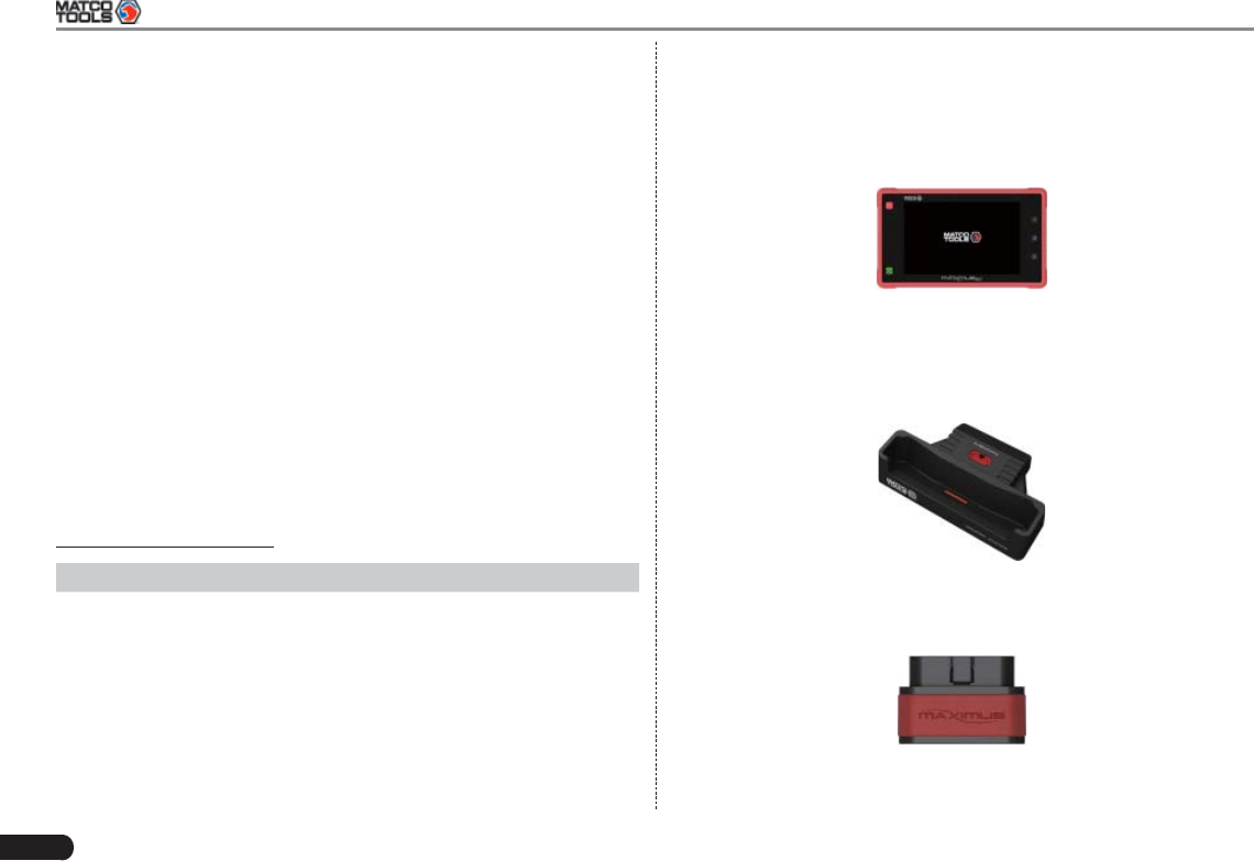
2 Knowledge of MAXIMUS2.0
There are three main components to the MAXIMUS2.0 system:
MAXIMUS2.0 Display Tablet -- the central processor and monitor •
for the system (For details, please refer to Chapter 2.1.)
Fig. 2-1
MAXIMUS2.0 Docking Station -- the platform for charing •
MAXIMUS2.0 display tablet and extending functions (For details,
please refer to Chapter 2.2.)
Fig. 2-2
Diagnostic Connector -- the device for accessing vehicle data (For •
details, please refer to Chapter 2.3.)
Fig. 2-3
Connectivity Wi-Fi (• 802.11 b/g/n)
USB: 2.0•
Bluetooth 2.0•
Ethernet: RJ45 Ethernet Connection•
Camera Front-facing, 2.0 megapixel; Rear-
facing, 5.0 megapixel, AF with
Flashlight
Sensors Gravity Accelerometer, Ambient Light
Sensor
Audio Input/Output Microphone•
Speakers•
3.5mm stereo headset jack•
Power and Battery 12000 mAh lithium-polymer battery
Charging via 5V DC power supply
Operating Temperature -10℃ ~ 55℃(14 ~131℉)
Storage Temperature -20℃ ~ 70℃(-4 ~158℉)
B. Diagnostic Connector
Item Description
Working temperature -10℃ ~ 55℃(14 ~131℉)
Storage temperature -20℃ ~ 70℃(-4 ~158℉)
Relative humidity 20% ~ 90%
MAXIMUS2.0 User's Manual
3
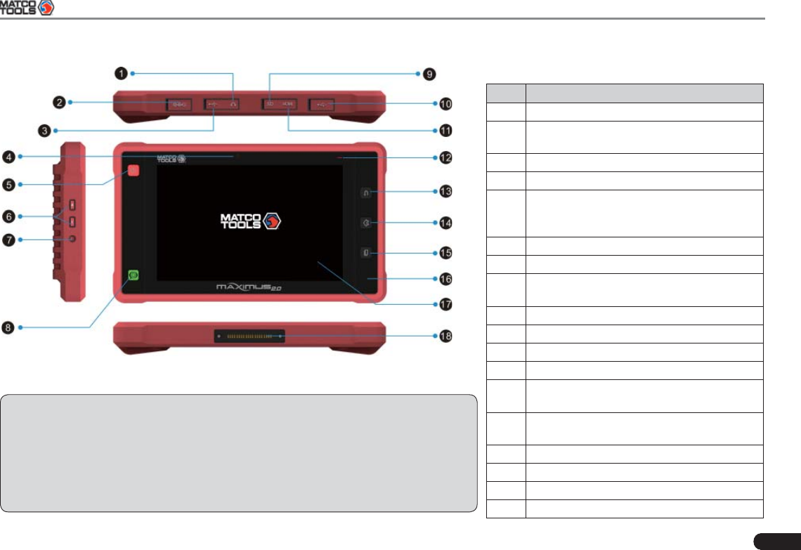
Table 2-1 formulates interfaces and indicators of
MAXIMUS2.0 display tablet (front):
No. Name & Descriptions
1Headphone Jack
2DC Input Port -- to connect the included
power adaptor.
3USB Port*1 (See Note1*)
4Front Camera Lens
5Screen Lock/Power Button -- to turn the
display tablet on/off with long press, or lock
the screen with short press.
6Volume Keys -- to adjust the volume.
7Reset Button
8golo Button -- for quick access to IM
(Instant Messager) application
9SD Card Slot -- to store the SD card.
10 USB Port*1 (See Note1*)
11 HDMI Port
12 Charging indicator*2 (See Note2*)
13 Return Button -- to return to the previous
screen.
14 Homepage Button -- to return to the
Android System's home screen.
15 Recent Apps Button*3 (See Note3*)
16 Microphone
17 IPS Touch Screen
18 Charging Slot
2.1 MAXIMUS2.0 Display Tablet
Fig. 2-4 MAXIMUS2.0 Display Tablet (front & side view)
Notes:
1. The USB ports together with 2 additional USB ports on the docking station are used
to connect USB devices. While extending optional functions, it is to be connected to
Scopebox, Sensorbox or Batterybox.
2. It illuminates red while MAXIMUS2.0 display tablet is charging. Once charging is
fi nished, it will turn green.
3. Press this button to display a list of applications that are currently working.
4
MAXIMUS2.0 User's Manual
Fig. 2-5 MAXIMUS2.0 Display Tablet (rear view)
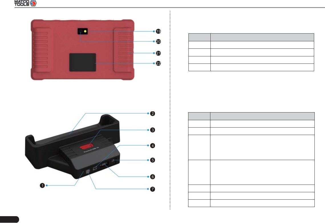
2.2 MAXIMUS2.0 Docking Station
Fig. 2-6 MAXIMUS2.0 Docking Station
Table 2-2 formulates parts of MAXIMUS2.0 display tablet
(rear):
No. Name & Descriptions
19 Camera Flash
20 Handgrip
21 Rear Camera Lens
22 Audio Speaker
Table 2-3 formulates ports of MAXIMUS2.0 docking station
No. Name & Descriptions
1Borescope Port
2Charging Slot -- to charge the display talbet.
3Powered OBD16 Socket -- Plug the diagnostic
connector into this socket for demo experience
when the docking station is connected to the
AC outlet.
4Ethernet Port -- to use wired network other
than Wi-Fi to access Internet, please install
the display tablet into the docking station and
connect the Ethernet cable to this port.
5Power Interface
6VGA Port
7USB Ports
MAXIMUS2.0 User's Manual
5
2.4 MAXIMUS2.0 Accessory Checklist
Common accessories for each MAXIMUS2.0 are same, but for
different destinations, the accessories of MAXIMUS2.0 (such as
diagnostic software, testing connectors) may vary. Please consult from
the local agency or check the package list supplied with MAXIMUS2.0
together.
Table 2-5 -- MAXIMUS2.0 common accessories and descriptions
No. Name Qt. Picture
1MAXIMUS2.0
Display Tablet 1
2Diagnostic
Connector 1
(To connect to vehicle’s DLC.)
3Docking Station 1
4Micro USB Cable 1(To connect on PC for data
transmission or upgrade DBScar
diagnostic connector)
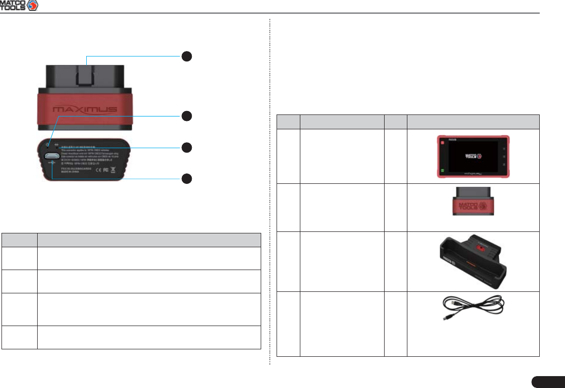
2.3 Diagnostic Connector
1
2
3
4
Fig. 2-7 Diagnostic Connector
Table 2-4 formulates ports and indicators of diagnostic connector:
No. Name & Descriptions
1OBD-16 Diagnostic Connector -- To connect on vehicle’s
OBD2 DLC.
2Power Indicator -- It lights up while the connector is
plugged into the vehicle’s DLC.
3Communication Indicator -- It will fl ash once the
connector is communicating with MAXIMUS2.0 or it is
being reset.
4Micro USB Port -- To connect on PC for data transmission
or upgrade via USB cable.
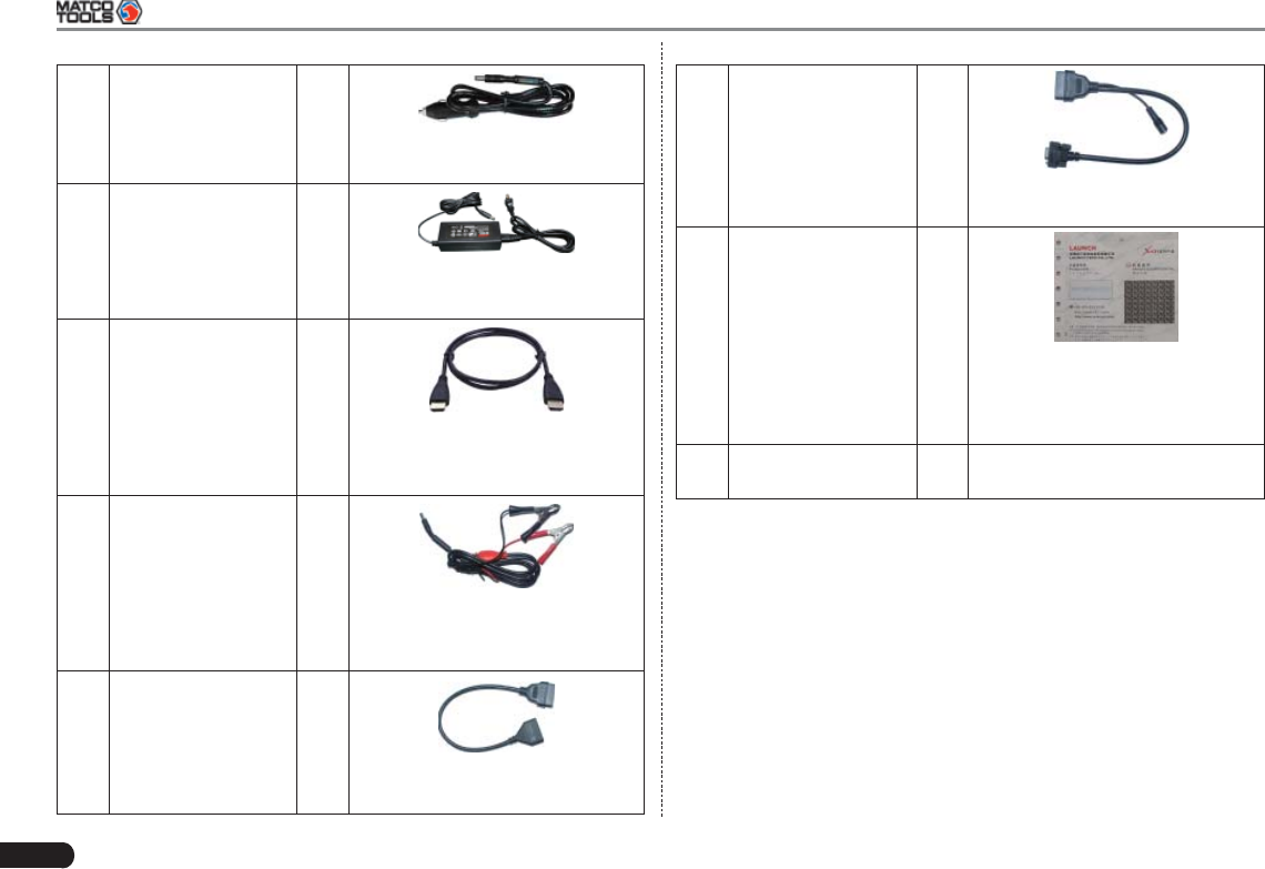
6
MAXIMUS2.0 User's Manual
5Cigarette Lighter
Cable 1
(To obtain power supply from
vehicle’s cigarette lighter )
6Power Adaptor 1
(To convert 100~240V AC power
supply to 5V DC power supply.)
7HDMI Cable 1
(To connect to an external
projector or monitor with HDMI
interface.)
8Clipper Cable 1
(To provide power to the non-16
pin connector through connection
to the vehicle's battery.)
9OBD II extension
cable 1
(To connect the diagnostic
connector for extension purpose.)
10 OBDI Adaptor 1
(A converting cable for connecting
non-16 pin connector.)
11 Password
Envelope 1
(A piece of paper bearing
Product S/N and Verifi cation
Code, which is required for your
registration.)
12 Non-16pin
Connector (Optional)
MAXIMUS2.0 User's Manual
7
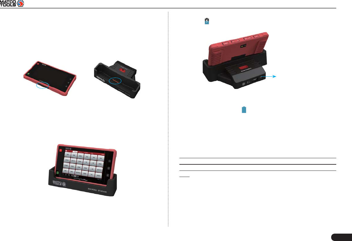
3 Preparations
3.1 Charging MAXIMUS2.0
Locate the charging slot on the bottom of MAXIMUS2.0 display 1.
tablet and the docking station. See Fig. 3-1 & Fig. 3-2.
Fig. 3-1 Fig. 3-2
Align the charging slots, and then dock the display tablet into the 2.
station to ensure that it is firmly seated on the docking station.
Refer to Fig. 3-3.
Fig. 3-3
Insert one end of the included power cord of the docking station 3.
into the power jack, then plug the other end into the AC outlet. See
Fig. 3-4. If appears on the screen, it indicates it is being charged.
To AC outlet
Fig. 3-4
If the logo changes into 4. , it indicates that the battery is fully
charged. Disconnect the docking station from the AC outlet.
3.2 On Using Your Battery
If the battery keeps unused for a long time or battery is completely •
discharged, it is normal in case it can not be turned on while being
charged. Please charge it for a period and then turn it on.
Please use the included power adaptor to charge your •
MAXIMUS2.0. We assume no responsibility for damage or loss
resulting from using other similar adaptors other than the specifi ed
one.
To prolong the service life of the battery, avoid charging too •
frequently.
The charging time of battery varies with temperature condition and •
battery consumption status.
While MAXIMUS2.0 has low battery, a beep will sound. If it is very •
low, MAXIMUS2.0 will be switched off automatically.
8
MAXIMUS2.0 User's Manual
3.3 Power On / Power Off MAXIMUS2.0
3.3.1 Power on
Press the POWER key to turn on MAXIMUS2.0.
Note: If it is the fi rst time you use MAXIMUS2.0 or MAXIMUS2.0
keeps idle for a long time, MAXIMUS2.0 could fail to be turned
on. It results from low battery. In this case, please recharge your
MAXIMUS2.0 for a while and try to turn it on.
3.3.2 Power off
Press the POWER key, an option menu will pop up on the screen.1.
Tap “Power off” to turn off MAXIMUS2.0.2.
3.4 Tips On Finger Operations
Actions Results
Single-tap To select a item or launch a program.
Double-tap To zoom in so that the text on a webpage appears
in a column that fi ts your device’s screen.
Long press Press and hold on the current interface or area
until a contextual menu pops up on the screen,
and then release it
Slide To jump to different pages.
Drag Tap the desktop icon and drop it to other location.
Spread apart /
Pinch together
To zoom in manually, place two fingers on the
screen and then spread them apart. To zoom out,
place two fingers apart on the screen and then
pinch them together.
3.5 Lock & unlock the screen
Many screen lock modes are available on MAXIMUS2.0. Take the
preset screen-lock mode as example for demonstration.
3.5.1 Lock the screen
When MAXIMUS2.0 is ON, press POWER key once to lock the •
screen;
The system will lock the screen automatically after MAXIMUS2.0 •
remains idle over the preset standby time.
3.5.2 Unlock the screen
Press POWER key to activate the screen, and then drag the lock to
“Unlock” position.
Note: If you defi ne as unlock using the pattern, you have to draw
the right target pattern to unlock it.
MAXIMUS2.0 User's Manual
9
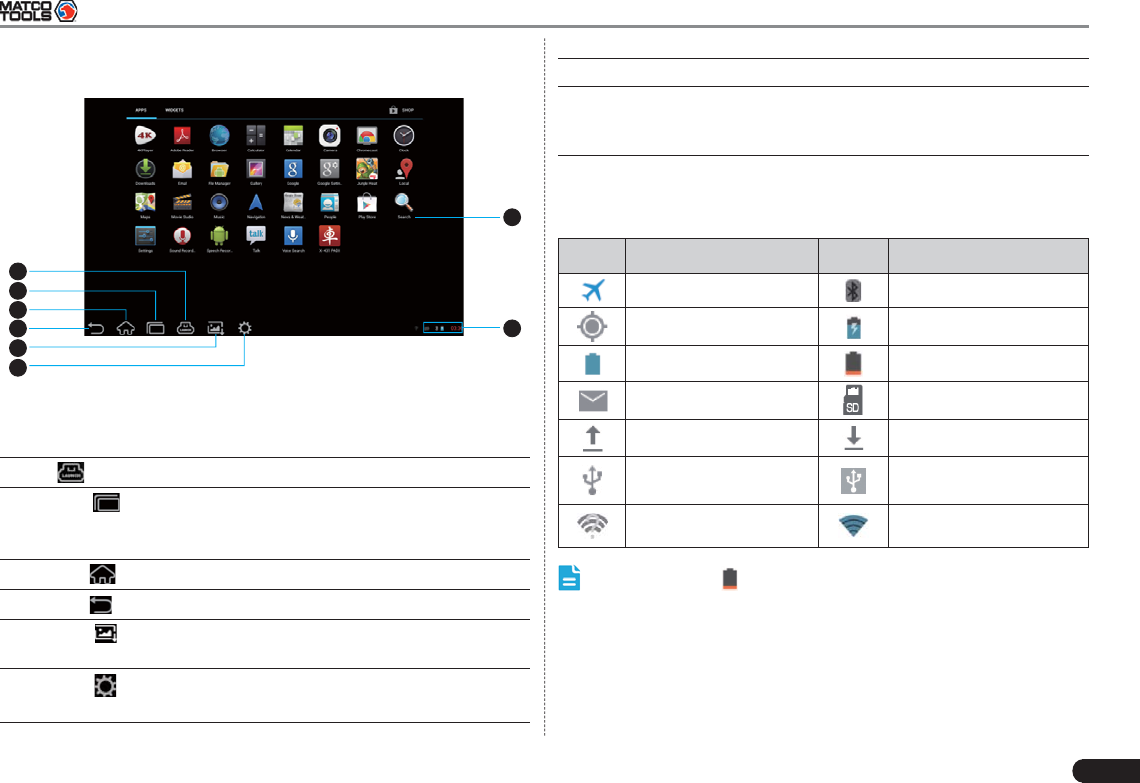
3.6 Screen Layout
1
7
8
2
3
4
5
6
Fig. 3-5
On-screen keys and status bar are as follows:
1 shows whether the diagnostic connector is connected.
2Tap to display a list of applications that are currently
running. To open an application, tap it. To remove an
application, swipe it upwards.
3Tap to jump to the Android System’s home screen.
4Tap
to return to the previous screen or exit the application.
5Tap
to capture the current screen and all captured
screenshots are stored in the Screenshots folder.
6Tap
to confi gure the MAXIMUS2.0 system settings and to
view the general information about the Display Tablet.
7 Display the widget and application icons.
8 It shows: System time, Wi-Fi connection status and signal
strength, battery status and other information. Tap the digital
clock to open the notice panel.
3.7 Status Bar
For some common indicators, please see the following table.
Icons Defi nitions Icons Defi nitions
Airplane mode Bluetooth is on
Positioning GPS Charging
Battery is fully charged Low battery
New mail Preparing SD card
Uploading Downloading
Connected to a PC USB bound is activated
Available Wi-Fi is
detected Connected to Wi-Fi
Notes: When the icon appears on the status bar, please charge
it immediately.
3.8 Notifi cation bar
The notification bar is used to display some activities, such as new
messages, to do list and running tasks. You can also open the
notifi cation bar to view the reminder or activity notifi cation.
10
MAXIMUS2.0 User's Manual
3.9 Customize your desktop
3.9.1 Move items on the desktop
Hold and press the item to be moved until it is shaken. 1.
Drag and drop it to the target location.2.
Note: Drag the icon to the margin of the screen and keep it still,
the system will switch to other extension desktop, place it to the
desired location.
3.9.2 Delete items from the desktop
Hold and press the item to be moved until it is shaken. 1.
Drag it on the trash icon, then release it.2.
Warning: Deleting an icon will uninstall the corresponding
application. Please be careful to do so.
3.9.3 Change your wallpaper
Hold and press a blank area on the desktop, a pop-up wallpaper 1.
window will be shown on the screen.
Set different wallpaper as desired:2.
• Wallpapers: Choose a still picture from gallery as wallpaper.
• Live Wallpapers: Open it to choose one of the preset live
wallpapers as wallpaper.
• Gallery: Set the photos you captured as wallpaper.
3.9.4 Adjust brightness
Tips: Reducing the brightness of the screen is helpful to save the
power of MAXIMUS2.0.
On the main menu screen, tap Settings > Display > Brightness.1.
Drag the slider to adjust it as desired.2.
3.9.5 Set standby time
If no activities are made within the defi ned standby period, the screen
will be locked automatically and the system enters sleep mode to save
power.
On the main menu screen, tap Settings > Display > Sleep.1.
Choose the desired sleep time.2.
3.9.6 Set screen lock
This function is designed to lock the screen and buttons to avoid
accidental operations while MAXIMUS2.0 keeps unattended.
On the main menu screen, tap Settings > Security > Screen lock.1.
Choose the desired screen lock mode and follow the on-screen 2.
instructions to fi nish your setting.
3.9.7 Adjust the volume
This option enables you to adjust the volume of the ringtones, media
player, alarm and notice.
On the main menu screen, tap Settings > Sound > Volume.1.
Drag the slider to adjust it.2.
Note: Alternatively, you can also press the volume keys to control
the volume of the current application.
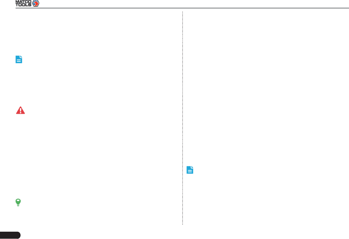
3.10 Input Method
3.10.1 Activate / hide on-screen keyboard
By default, Android keybaord is available on MAXIMUS2.0.
To input text, tap the input box and the on-screen keyboard will be •
MAXIMUS2.0 User's Manual
11
activated automatically.
After inputting, tap • to hide the keyboard.
Note: In some applications, the on-screen keyboard may appear
over some interfaces partially. Close it to view more so that you can
judge what’s next to do.
3.10.2 Edit text
Cut, copy and paste operations are supported.
Tap and hold the desired text area until a blue cursor appears. 1.
Press and drag the cursor to highlight the text to be edited. 2.
Tap SELECT ALL, CUT or COPY to perform the corresponding 3.
operations. To delete the selected text, tap the delete key on the
keyboard.
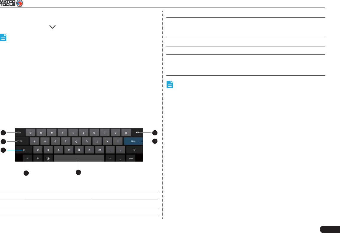
3.10.3 Android input method
1 7
6
2
3
45
Fig. 3-6
1 To jump to next textbox.
2 To switch to numeric & symbol keyboard.
3 To toggle between upper case and lower case.
4 To bring up an input options menu. Input languages and
Android keyboard settings such as auto-capitalization and
sound on keypress are available.
5 To enter a space.
6 Line feed.
7 > To delete the character before the cursor.
> Long-press this key to delete all characters before the
cursor.
Note: For different input box, keyboard layout may vary. The fi gure
shown as above is provided for reference purpose.

12
MAXIMUS2.0 User's Manual
4 Wi-Fi Setting
Note: Once Wi-Fi is set as ON, MAXIMUS2.0 will consume more
power. While Wi-Fi keeps unused, please set it off to save power.
On the main menu screen, tap Settings > Wi-Fi.1.
Tap or slide the Wi-Fi switch to ON, MAXIMUS2.0 starts searching 2.
all available wireless LANs.
Choose the desired Wi-Fi,3.
If the network you chose is open, you can connect on it directly;•
If the selected network is encrypted and secured with WPA, you •
have to input the right access password to connect.
Once it is connected successfully, tap the Wi-Fi from the list to view its
name, link speed, security type, IP address etc.
When MAXIMUS2.0 is in range of the WLAN, it will connect to the
previously linked network automatically.
5 How to diagnose
5.1 Connections
5.1.1 Preparation
Normal testing conditions
Turn on the vehicle power supply.•
Vehicle battery voltage range should be 9-14V and working voltage •
of MAXIMUS2.0 is 5V.
Throttle should be closed at its close position. •
Ignition timing and idle speed should be within specified range; •
water and transmission oil temperature are within normal working
range (water temperature is 90-110℃ and transmission oil
temperature is 50-80℃).
Select testing connectors
If MAXIMUS2.0 is testing vehicles equipped with universal OBD II 16
PIN diagnostic socket, please use the included diagnostic connector.
(For vehicles with non-OBD II 16 PIN diagnostic socket, a non-16 PIN
connector is required.)
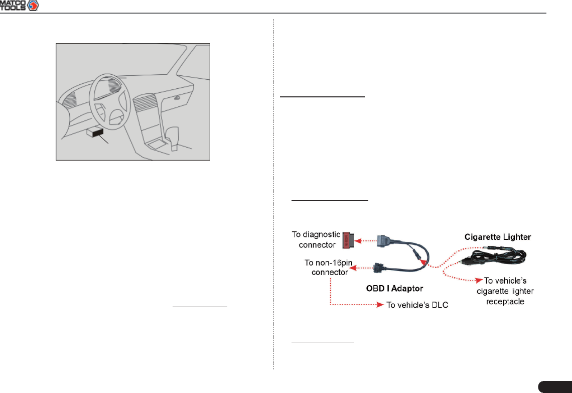
5.1.2 DLC Location
The DLC (Data Link Connector or Diagnostic Link Connector) is the
standardized 16-cavity connector where diagnostic code readers
interface with the vehicle’s on-board computer. The DLC is usually
located 12 inches from the center of the instrument panel (dash), under
or around the driver’s side for most vehicles. If Data Link Connector is
not located under dashboard, a label should be there telling location.
For some Asian and European vehicles, the DLC is located behind the
ashtray and the ashtray must be removed to access the connector. If
the DLC cannot be found, refer to the vehicle’s service manual for the
MAXIMUS2.0 User's Manual
13
location.
Near the center
of dashboard
Fig. 5-1
5.1.3 Vehicle Connection
The method used to connect the diagnostic connector to a vehicle’s
DLC depends on the vehicle’s confi guration as follows:
A vehicle equipped with an OBD II management system supplies •
both communication and 12V power through a standardized DLC.
A vehicle not equipped with an OBD II management system •
supplies communication through a DLC connection, and in some
cases supplies 12V power through the cigarette lighter receptacle
or a connection to the vehicle battery.
Follow the steps mentioned below to connect OBD II vehicle:
Locate vehicle’s DLC socket. 1.
Plug the diagnostic connector into the vehicle’s DLC socket (It 2.
is suggested to use the OBD II extension cable to connect the
diagnostic connector and DLC socket.).
Choose one of the two ways to obtain power from:3.
A. Power adaptor: connect one end of the included power adaptor
to Power interface of MAXIMUS2.0 display tablet, and the other
end to AC outlet.
B. Internal battery pack: For details on how to recharge
MAXIMUS2.0, see “Chapter 3.1 Charging MAXIMUS2.0”.
For non-OBDII vehicle, proceed as follows:
Locate vehicle’s DLC socket. 1.
Select the corresponding non-16pin connector.2.
Plug the non-16pin end of the connector into the DLC socket, then 3.
connect the other end to the OBD I adaptor, and then tighten the
captive screws.
Connect the other end of the adaptor to the included diagnostic 4.
connector.
To supply power to OBD I adaptor from:5.
A. Cigaretter Lighter: Connect one end of the cigarette lighter cable
to vehicle’s cigaratte lighter receptacle, and the other end to the
power jack of OBDI adaptor.
Fig. 5-2
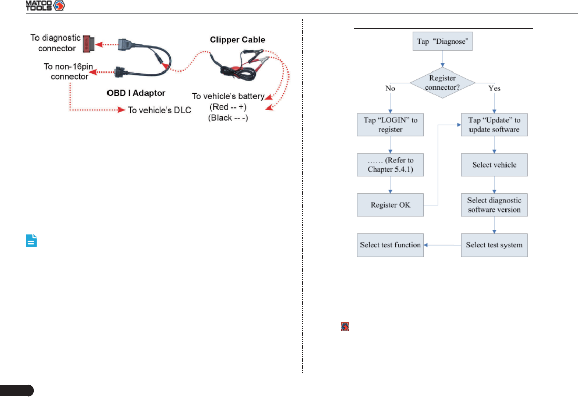
B. Clipper Cable: Connect one end of the clipper cable to vehicle’s
battery, and the other end to the power jack of OBDI adaptor.
14
MAXIMUS2.0 User's Manual
Fig. 5-4
5.4 User and Connector Registration
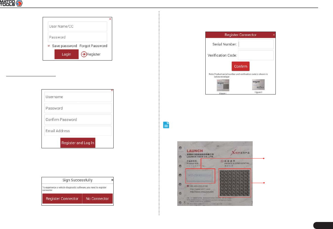
5.4.1 User registration
Tap the icon on the desktop to launch the application, a disclaimer
page will pop up on the window. Tap “I’ve read it”, and tap “LOGIN” to
enter the login interface of diagnosis software, as indicated in Fig. 5-5.
Fig. 5-3
5.2 Bluetooth Setting
Enter MAXIMUS2.0 Bluetooth setting screen (“Settings” -->
“WIRELESS & NETWORK” --> “Bluetooth”), slide the Bluetooth switch
to ON and MAXIMUS2.0 will start searching available Bluetooth
device, click the desired connector to pair and match.
By default, the Bluetooth name is 98419*****00 (where ***** stands for
5 digits.).
Note: In case no Bluetooth setting is done before diagnostic
software is launched, you can also configure it while using the
software. For details on Bluetooth connection, please refer to “Chapter
5.6 Start diagnosing”.
5.3 Diagnosis Flowchart
For new users, please follow the operation chart shown in Fig. 5-4 to
get familiar with and start using MAXIMUS2.0.
MAXIMUS2.0 User's Manual
15
Fig. 5-5
1. If you are a new user, click “Register” to enter registration page.
See Fig. 5-6.
Fig. 5-6
In Fig. 5-6, fill in the information in each field. After inputting, click
“Register and Log In”, a prompt message similar to the following will
appear:
Fig. 5-7
In Fig. 5-7, click “Register Connector” if you want to experience vehicle
diagnostic software. See Fig. 5-8.
Fig. 5-8
To exit and register it later, click “No connector”.
Input the Serial Number and Verifi cation Code, and then click “Confi rm”.
Note: The Serial Number and Verifi cation Code can be obtained
from the password envelope. See Fig. 5-9.
Product S/N
Verifi cation Code
Fig. 5-9
16
MAXIMUS2.0 User's Manual
Alternatively, you can also register your connector by clicking “Activate
Device” in “Profi le”. For details, please refer to Chapter 5.7.3 Activate
Device.
2. If you have registered to be a member, input your name/CC and
password in Fig. 5-5, and then click the “Login” button to enter the
main menu screen directly.
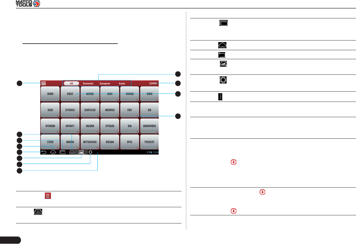
5.4.2 Diagnostic software layout
2
3
4
5
110
11
12
9
6
7
8
Fig. 5-10
1Tap to pull down all function menu. Refer to “Chapter
5.4.3 Function menu” for details.
2 shows whether the diagnostic connector is properly
connected or not.
3Tap to display a list of applications that are currently
running. To open an application, tap it. To remove an
application, swipe it upwards.
4Tap to jump to the Android System’s home screen.
5Tap
to return to the previous screen or exit the application.
6Tap
to capture the current screen and all captured
screenshots are stored in the Screenshots folder.
7Tap
to confi gure the MAXIMUS2.0 system settings and to
view the general information about the Display Tablet.
8Tap to fi nd more applications.
9 Vehicle region buttons: Tap different buttons to switch to
corresponding vehicles.
10 Login button: Tap it to log in or register the diagnostic system.
Once users have logged in successfully, it will change to your
user name.
11 Vehicle diagnosis software logo: To start diagnosing a
vehicle, you have to download the corresponding diagnostic
software. In case a diagnostic software is downloaded and
installed, will disappear.
For details on downloading or updating a software, please
refer to “Chapter 5.5 Download/ Update Diagnostic
Software”.
12 Downloadable logo: shown at the lower right corner of
the vehicle software logo means that this diagnosis software
is downloadable. Once it is successfully downloaded and
installed, will disappear.
MAXIMUS2.0 User's Manual
17
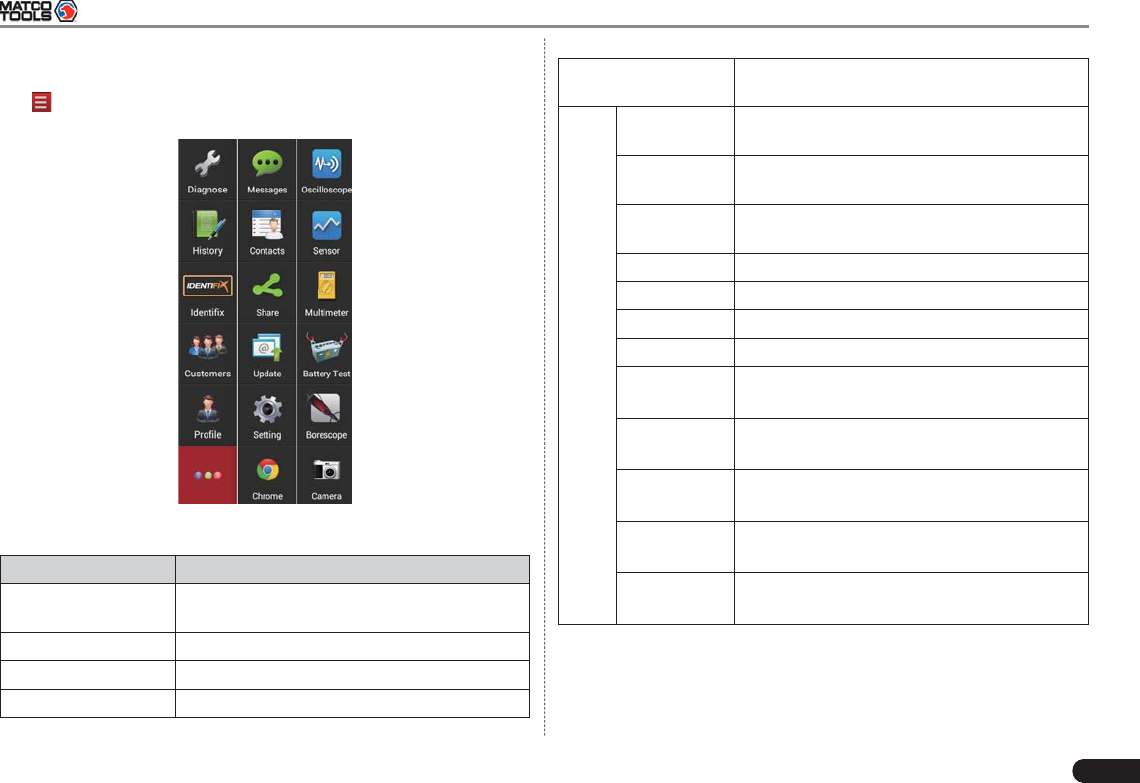
5.4.3 Function menu
Tap to unfold function menu, it mainly includes the following items:
Fig. 5-11
Name Description
Diagnose Configures MAXIMUS2.0 to operate as a
diagnostic tool.
History (Coming soon)
Identifi x An speed-dial to Identifi x website.
Customers (Coming soon)
Profi le Accesses to My Report, Activate Device,
Private information and Settings etc.
More
Messages To launch IM (Instant Messager) application.
(Coming soon)
Contacts To manage your friend and accounts.
(Coming soon)
Share To share information with others, including
text, voice, images and fi les. (Coming soon)
Update To dowload or update vehicle software.
Setting Allows you to confi gure system settings.
Chrome Launches the Chrome brower.
Camera Opens the camera.
Oscilloscope
(Optional)
To determine vehicle electrical equipment
and circuit trouble. (Coming soon)
Sensor
(Optional)
To diagnose/simulate vehicle ECU sensor
trouble.
Multimeter
(Optional)
To measure physical parameters such as
voltage, resistance, frequency etc.
Battery Test
(Optional)
To test whether vehicle's battery is good or
not.
Borescope
(Optional)
To check unseen or unreachable parts or
components. (Coming soon)
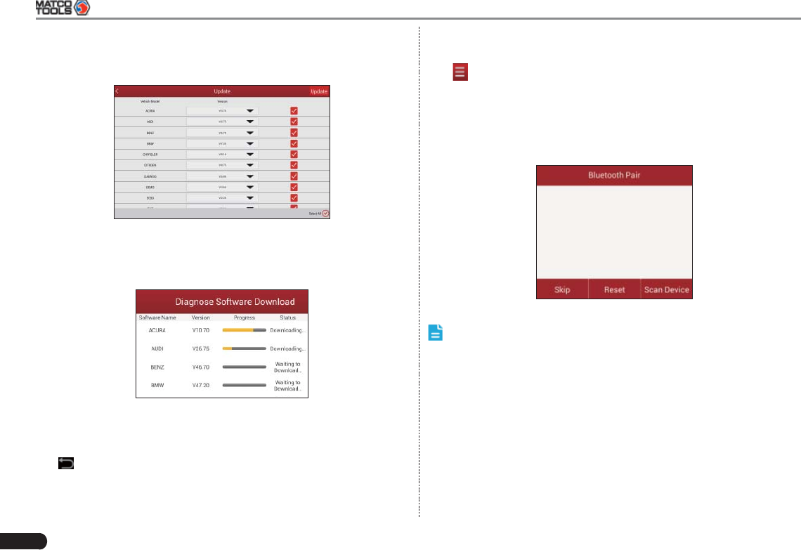
5.5 Download/ Update Diagnostic Software
Before diagnosing a vehicle, you have to download the corresponding
vehicle diagnosis software.
18
MAXIMUS2.0 User's Manual
In Fig. 5-11, tap “Update” to select the paired diagnostic connector.
Tap the serial number and a list of diagnostic software will pop up on
the screen.
Fig. 5-12
By default, all diagnostic software are selected. To select certain
software, Tap “Select All”, and then uncheck the box next to Version.
Tap “Update” to start downloading.
Fig. 5-13
Once it is complete, the system will decompress automatically and
then install it.
Tap to the main menu screen.
5.6 Start Diagnosing
Tap on the main menu screen, and then choose “Diagnose” to
enter the vehicle selection page.
Take Demo as an example to demonstrate how to diagnose a vehicle.
1. Tap the “Demo” logo, the system will prompt you to make Bluetooth
pair firstly (See Fig. 5-14). Since Bluetooth is not required for
DEMO program, just tap “Skip” to proceed to Step 2.
Fig. 5-14
Note: Generally you have to match and pair Bluetooth while
diagnosing a certain vehicle. If Bluetooth pair has been done, “Not
Connected” but “Paired” will appear on the screen. Tap the desired
connector to start connecting. If successful, a pop-up message
“Connected to 98419*****00” will be shown.
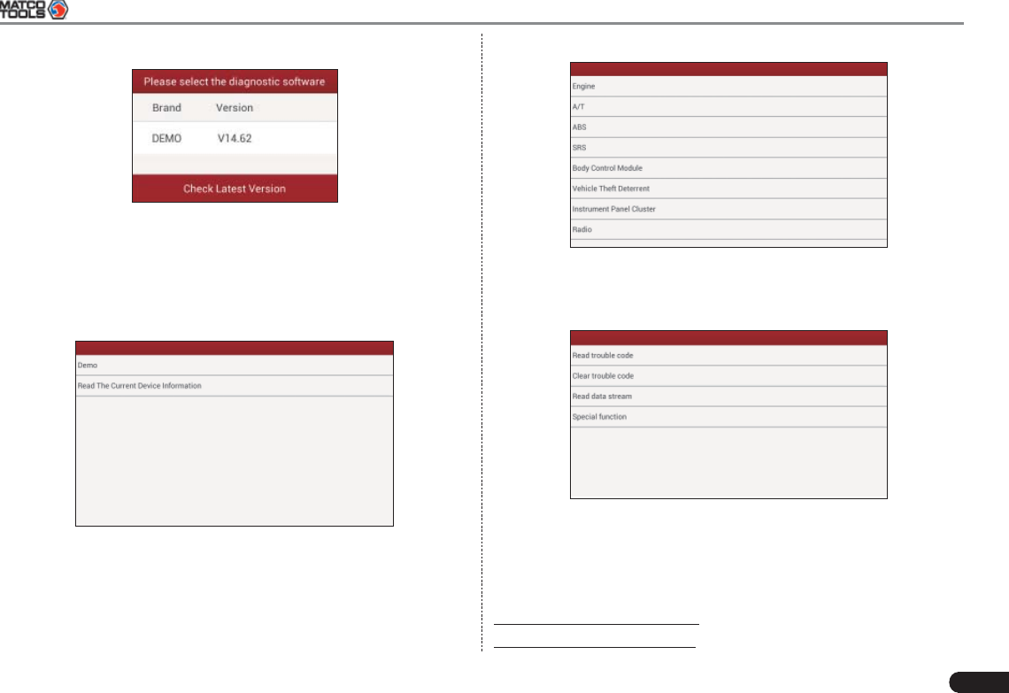
2. After Bluetooth is properly connected, the system will enter
software version selection screen. See Fig. 5-15.
MAXIMUS2.0 User's Manual
19
Fig. 5-15
To check whether a new version is available or not, click “Check Latest
Version”. If a newer version is detected, it will start downloading the
latest version.
3. Tap the desired version to start initializing. After initializing is
complete, the screen will display as below:
Fig. 5-16
4. Tap “Demo” to enter system selection interface. See Fig. 5-17.
Fig. 5-17
5. Tap “Engine”, the system will jump to the function menu. See Fig.
5-18.
Fig. 5-18
5.6.1 Read Trouble Code
Tap “Read Trouble Code” in function menu, the screen will display the
diagnostic result.
Generate Current Text Reports: To save the current data in text format.
Generate Screenshot Reports: To save the current data in screenshot
20
MAXIMUS2.0 User's Manual
form.
5.6.2 Clear Trouble Code
Tap “Clear Trouble Code” function menu, the system will automatically
delete the currently existing trouble code.
Note: The trouble code will not disappear until the trouble was
completely cleared.
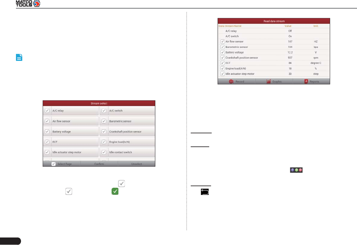
5.6.3 Read Data Stream
Tap “Read Data Stream” in function menu, the system will display data
stream items.
Fig. 5-19
To select certain data stream item, just tap , then the selected item
will be activated and will change into .
To select all items of the current screen, tap “Select Page”, and then
tap “Confi rm” to enter data stream reading interface. See Fig. 5-20.
To deselect all items, tap “unselect”.
Fig. 5-20
After selecting, tap “Graphic”, the system will display data changes in
waveform.
To start to record, tap “Record”; To stop reading, click “Stop”.
On data stream reading page, the following operations can be done:
Graphic: Tap to select the desired datastream to be browsed, and
then tap it to view the waveform.
Record: Tap to start recording diagnostic data for future playback and
view. The saved file follows the naming rule: It begins with vehicle
type, and then the record starting time and ends with .x431 (To
differentiate between fi les, please confi gure the accurate system time).
The file is stored in “My Report” under menu. For details on
playback operations, please refer to Chapter 5.7.1 “My Report”.
Reports: To save the current data in text format.
Tap to return to the function selection screen.
5.6.4 Special Function
This option allows you to detect whether the system parameters are
normal or not. It mainly includes: Injector test, fuel pump test, purge
control solenoid and so on.
MAXIMUS2.0 User's Manual
21
Fig. 5-21
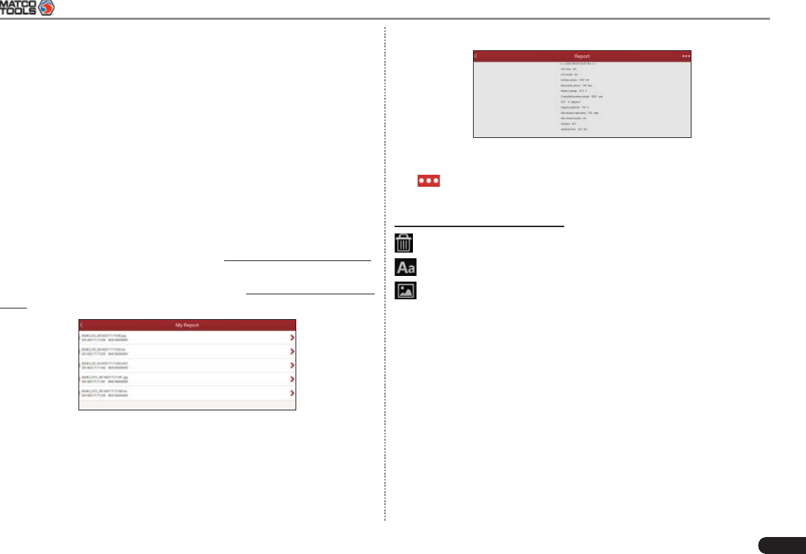
Tap to view and perform more operations.
Tap certain diagnosis playback fi le (.x431) to view it.
On-Screen button defi nitions:
Delete: To delete the current report;
Character: To view the diagnostic report in character form.
Graph: To view the diagnostic report in waveform form.
5.7.2 Orders
This option is specially designed to facilitate on-line purchase. You can
check unpaid orders, paid orders and shopping cart. To make an on-
line order, just follow the on-screen instructions to proceed.
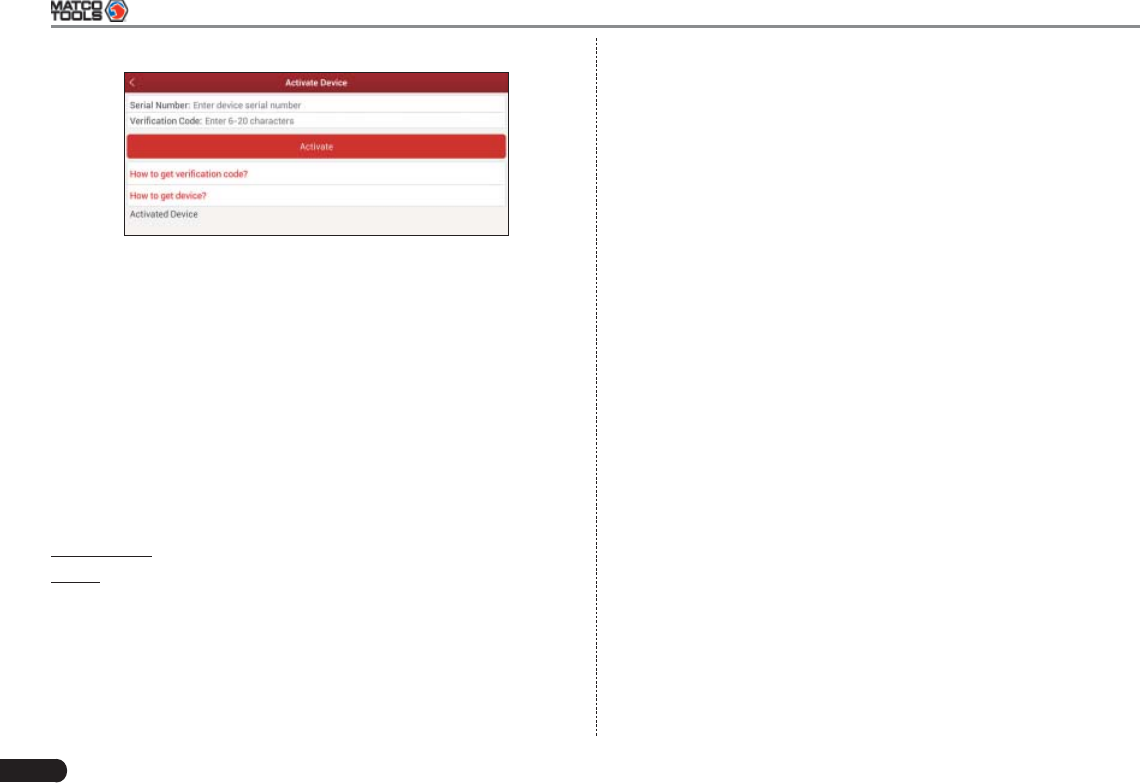
5.7.3 Activate Device
It is used to register your diagnostic connector.
Take “1# injector” as an example.
To detect whether 1# injector works normally or not, click “1# injector”,
the system will automatically carry out the function. After complete, a
prompt dialog box will pop up on the screen.
5.7 Profi le
This function allows users to manage your profi le.
5.7.1 My Report
This option is used to view the diagnostic report generated in process
of vehicle diagnosis. Additionally, delete, send operations are also
supported.
Tap “My Report”, a list of diagnostic report will appear below the tab.
If user records the running parameters while reading data stream,
.x431 fi le will be shown on the screen.
In case the DTC result is saved as .txt file on Read Trouble Code
page, .txt fi le will be displayed on the screen.
Fig. 5-21
Tap certain diagnostic report (.txt) to view it. See Fig. 5-24.
22
MAXIMUS2.0 User's Manual
Fig. 5-26
Input the Serial Number and Verifi cation Code, and then tap “Activate”
to register the connector.
For details on how to obtain Serial Number and Verifi cation Code, tap
the below links to get help.
5.7.4 Private Information
Use this item to view and confi gure your personal information.
5.7.5 Settings
It enables you to make some application settings and view software
version information and user manual etc.
App Settings: This item allows you to set the measurement unit.
About: Version Information, Version Update, Quick Start Guide, User
Manual are included.
5.7.6 Logout
This option allows you to log out the system.
To log out the current user ID, tap “Logout”.
MAXIMUS2.0 User's Manual
23
6. Sensorbox (Optional)
6.1 Product summary
MAXIMUS2.0 provides an optional function of automotive sensor
simulation test. “Sensor” function is specially designed to diagnose
and simulate vehicle sensor faults quickly and conveniently, including
“DC voltage simulation”, “Fixed frequency simulation”, “Predefined
waveform simulation” and “Hand-painted waveform simulation”.
Vehicle sensors are the signal input devices for electrical control
systems, which can transform all kinds of running parameters, such
as vehicle speed, coolant temperature, engine RPM, air fl ow, throttle
opening, etc., into the electronic signal for the vehicle computer who
can optimize the engine running status per the above-mentioned
parameters to keep the engine working in a prime status.
Meanwhile, it integrates the functions of automobile multimeter, which
enables users to perform voltage, resistance and frequency test. (The
function utilizes the same hardware device as the sensor module)
It features automotive sensor simulation test and multimeter test
function.
Sensorbox
Parameters Scope
Precision ±5%
Voltage range -5V~+5V
Max output current 70mA
Predefi ned frequency range 0~150Hz
Square-wave signal pulse frequency 0~15KHz
Square-wave signal duty ratio 10%~90%
Multimeter
Parameters Scope
Precision ±5%
Voltage test Testing range DC-400V~+400V
Input impedance 10Mohm
Resistance test Testing range 0~40Mohm
Frequency test Testing range 0~25KHz
Input impedance 1000Gohm
Input voltage 1~12V
6.2 Structure and Accessories
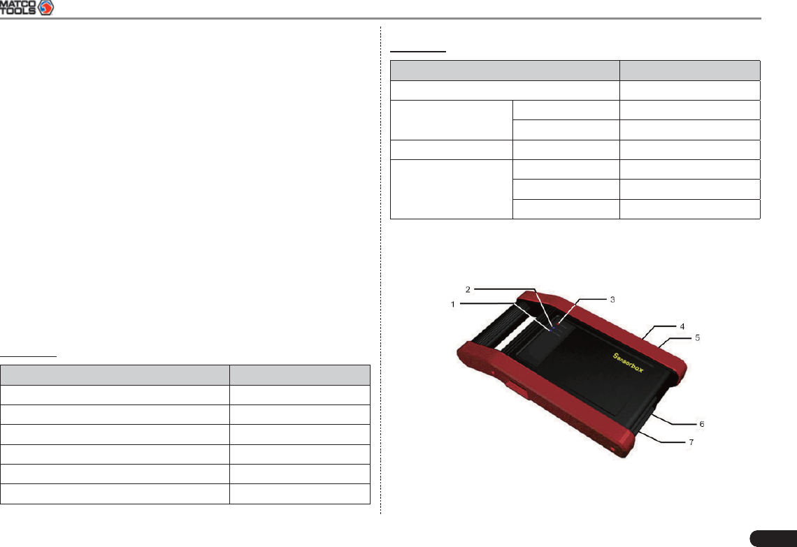
6.2.1 Sensorbox structure
Fig. 6-1 Structural diagram of Sensorbox
Table 6-1 shows the ports and indicators for MAXIMUS2.0 sensorbox
24
MAXIMUS2.0 User's Manual
No. Name Description
1Data receiving indicator Indicator (green) for receiving data
from main unit.
2Data sending indicator Indicator (green) for sending data to
main unit.
3Power indicator I t keeps steady on (red) after
Sensorbox is powered on.
4B type USB port Connect to main unit with USB cable
when it is applied as separated USB
device.
5Power connector Connect to power supply through the
power adaptor.
6COM Common terminal of multimeter
7VΩHz Testing terminal of multimeter
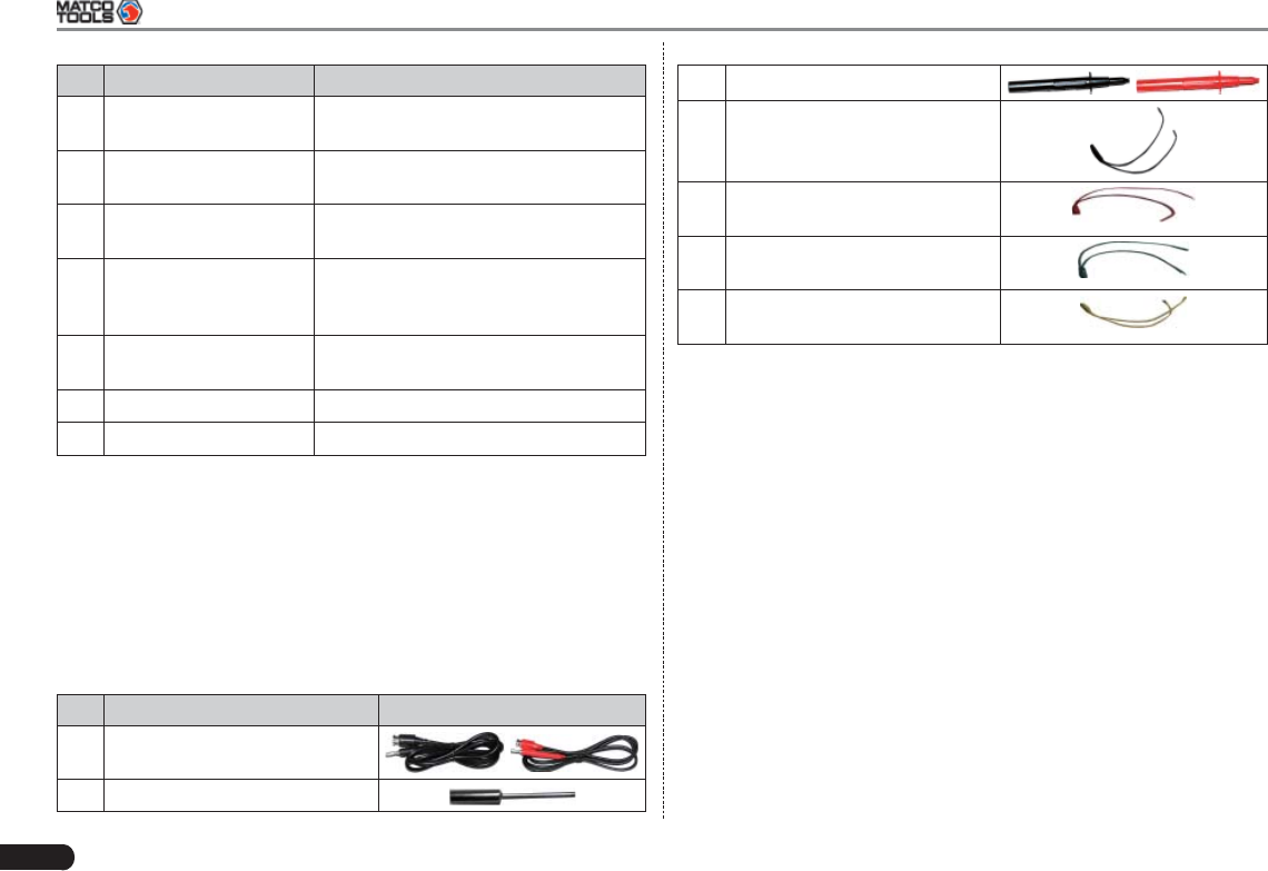
6.2.2 Sensorbox accessories
MAXIMUS2.0 sensorbox accessories include sensor test cable, probe
etc. See Table 6-2.
As the product confi guration can be different, the accessories included
with the product may differ from the accessories listed on this manual.
Please see the packing list attached to the product for the detailed
accessories.
Table 2-2 Accessory checklist
No. Name Picture
1Sensor test cable
2Sensor probe
3 Multimeter probe
4Electronic control converting
cable 1
5Electronic control converting
cable 2
6Electronic control converting
cable 3
7Electronic control converting
cable 4
6.3 Sensor Simulation
6.3.1 Connections
Firstly, power on the main unit (Connect one end of the power 1.
adaptor into the power interface of MAXIMUS2.0 main unit, and the
other end to the AC 220V outlet.);
Plug one end of the sensor test cable (black) into the “COM” 2.
interface of the sensorbox, then connect the other end to the test
probe or electronic control converting cable;
Connect one end of the sensor test cable (red) into the “VΩHz” 3.
interface of the sensorbox, and then connect the other end to the
test probe or electronic control converting cable.
Note: Choose corresponding cables and test probes according to
different terminals.
6.3.2 Simulation test
Simulation test enables users to exactly judge if the sensor is good or
not to avoid replacing components blindly. For example, the trouble
MAXIMUS2.0 User's Manual
25
code indicates the fault is in water temperature sensor itself. But we
need to confirm whether the fault results from water temperature
sensor or the connections between ECU and sensors, or ECU itself.
In this case, we can make full use of simulation test to input the signal
of simulating water temperature sensor, instead of water temperature
sensor, to the microcomputer. If the engine works better and the fault
vanishes, the fault is in the water temperature sensor. If the fault
still occurs, input the signal to the corresponding terminals of ECU.
Consequently, if the fault disappears, the fault lies in the connection
between water temperature sensor and ECU, otherwise, the fault
exists in ECU.
After all connections are properly made (refer to Chapter 6.3.1 for
details), power on your MAXIMUS2.0, launch MAXIMUS2.0 application
and enter the function menu interface, then tap “Sensor” to enter the
test selection screen. See Fig. 6-2.
Fig. 6-2
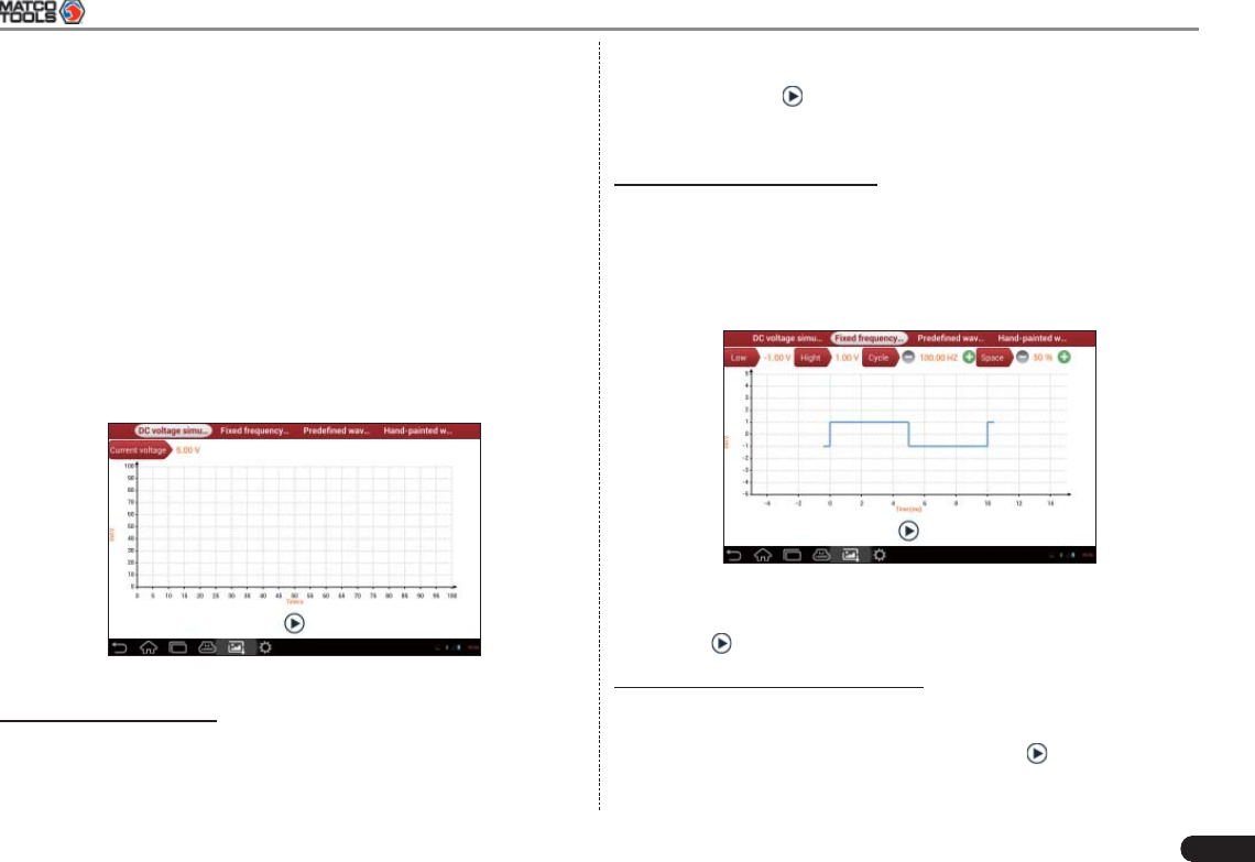
1. DC voltage simulation
In Fig. 6-2, tap [Current voltage], then tap “+” or “-” to adjust the output
voltage value. Alternatively, user can also click edit box, then use the
on-screen keyboard to input the desired value directly. After selecting
or inputting the desired voltage based on the working characteristics
of sensor, tap the button, then the MAXIMUS2.0 will begin to
output the simulation voltages. Please note the red probe is the output
terminal of simulation voltage.
2. Fixed frequency simulation
This option enables you to simulate the square wave signal of pulse
frequency of 0.1 ~ 15 kHz, amplitude range of -5V ~ +5 V and duty
cycle 10% ~ 90%.
In Fig. 6-2, tap “Fixed frequency simulation” to enter a screen similar
to Fig. 6-3.
Fig.6-3
Tap the setting option tab, then tap “+” or “-” to adjust the output,After
setting, tap to perform the test.
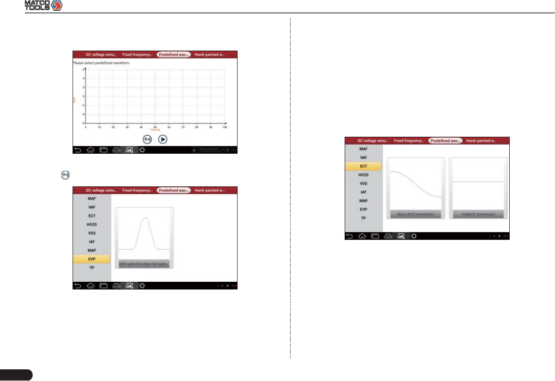
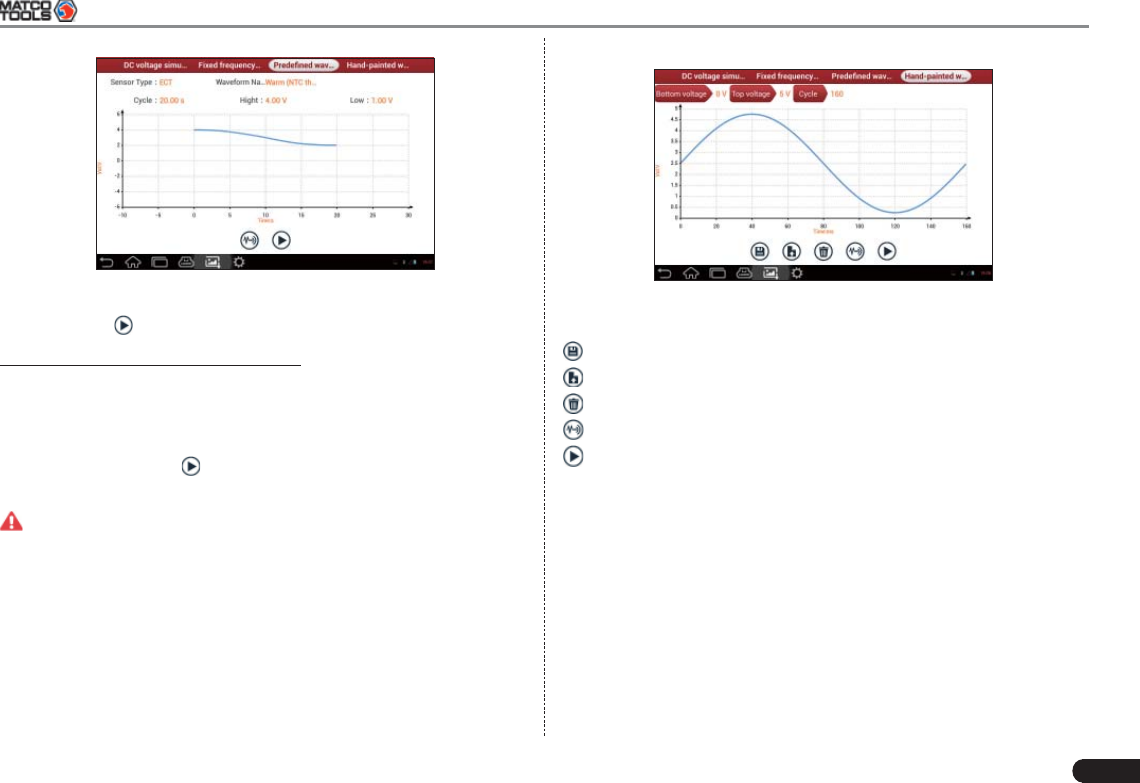
3. Predefi ned waveform simulation
MAXIMUS2.0 provides some common sensor waveforms which have
been predefi ned to facilitate users to simulate sensor signals. As long
as you call out the predefi ned waveform, then tap to start simulating
output of corresponding sensor waveform and no more parameter
settings of simulation waveform are required.
26
MAXIMUS2.0 User's Manual
In Fig. 6-3, tap “Predefi ned waveform simulation” to enter the screen
shown as Fig. 6-4.
Fig. 6-4
Here, tap button, a screen similar to Fig. 6-5 will appear.
Fig. 6-5
In Fig. 6-5, the left setting column stands for sensor types and the right
area displays waveform. The sensor types are explained as below:
ECT: Coolant Temperature Sensor
EVP: EGR Valve Position Sensor
HO2S: Heated Oxygen Sensor
IAT: Intake Air Temperature Sensor
MAF: Mass Air Flow Sensor
MAP: Manifold Absolute Pressure Sensor
TP: Throttle Position Sensor
VAF: Volume Air Flow Sensor
VSS: Vehicle Speed Sensor
For example, tap “ECT” – “Warm (NTC Thermistor)” in Fig. 6-5, the
right screen will display the waveform of the sensor. See Fig. 6-6.
Fig. 6-6
In Fig. 6-6, tap the waveform, then the pre-defi ned waveform has been
set. See Fig. 6-7.
MAXIMUS2.0 User's Manual
27
Fig. 6-7
In Fig. 6-7, tap button to perform simulation test.
4. Hand-painted waveform simulation
This option offers great convenience for users to simulate special
waveform or fault wave. Users only draw the shape of waveform which
needs to be simulated in central drawing area, and then configure
some parameters on the top, namely high level, low level, and cycle
of waveform, then tap , MAXIMUS2.0 will output a waveform as
desired.
Warning: Just draw a complete periodic waveform (when it is
outputted, the system will regard the waveform in the drawing area as
a periodic one). Users should draw an as large as wave in drawing
zone so that the system can sample more points to reduce tolerance.
While drawing, just pay attention to the shape of waveform, high level,
low level and period can be ignored, which can be set in the Confi gure
option.
In Fig. 6-2, tap “Hand-painted waveform simulation”, a screen similar
to Fig. 6-8 will appear.
Fig. 6-8
Button descriptions:
[]: save the current waveform.
[]: loads the previously saved hand-drawn waveform.
[]: clear all hand-drawn waveform.
[]: click to call out the predefi ned waveform for reference.
[]: continues the following operation.
6.3.3 Precautions on checking vehicle sensor
Hold the connector when plugging or unplugging it. Do not pull the •
cable for unplugging.
At fi rst check the fuse, fusible line and terminals. Then check others •
after eliminating these faults.
When measuring voltage, the ignition switch should be on and the •
battery voltage should not be less than 11V.
When measuring voltage, please shake the lead lightly in the •
vertical and horizontal direction for more precision.
When checking whether there is open in the line, disconnect the •
CEU and the relevant sensor at fi rst, then measure the resistance
28
MAXIMUS2.0 User's Manual
among the ports of sensor in order to determine whether open-
circuit / contact fault exists or not.
When checking if there is a short in the line, please disconnect the •
CEU and the relevant sensor, then measure the resistance value of
the ports between the connected port and the vehicle body. If the
resistance value is more than 1MΩ, no fault occurs.
Before disassembling the engine electrical control system cable, •
cut off the power supply, that is, turn the ignition switch OFF and
disconnect the cables on the battery poles.
Contact the test probe and the two terminals/ the two leads to be •
measured when measuring the voltage between the two terminals
or the two leads.
Contact the red test probe to the terminal/ the cable to be •
measured, and the black probe to the ground when measuring
voltage of one terminal/ one cable.
When checking the continuity of the terminals, contacts and leads, •
the method for measuring their resistances can be used.
Check the faults in the terminals of the CEU to sensors, relays, etc.•
There are two test probes in the testing wire. The black one is the •
common signal terminal (signal GND); the red one is the input
terminal for voltage, resistance, and frequency test and output
terminal for simulation voltage, simulation frequency and oxygen
sensor. Please choose the correct probes to match the different
terminals.
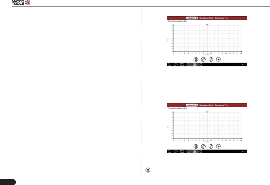
6.4 Auto Multimeter
6.4.1 Main Menu
Make sure MAXIMUS2.0 main unit and the sensorbox are properly
connected (Refer to Chapter 6.3.1 Connections for details), power on
MAXIMUS2.0 and enter the function menu interface, tap “Multimeter”
to display the test menu. See Fig. 6-9.
Fig. 6-9
Click the desired test as shown on Fig. 6-9 to perform related test.
The operation method on Resistance test and Frequency test is
identical to that of Voltage test. Here just take Voltage test as an
example for demonstration.
Tap “Voltage test”, a screen similar to Fig. 6-10 appears:
Fig. 6-10
The following operations can be done:
[]: erases the currently displayed waveform and display it starting
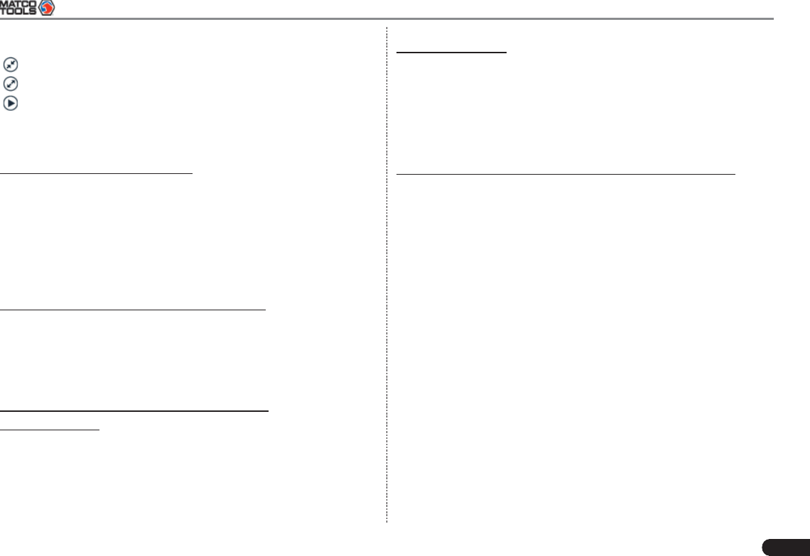
MAXIMUS2.0 User's Manual
29
from the left.
[]: reduces the range and zoom in the waveform.
[]: increase the range and zoom out the waveform.
[]: starts or stops the testing process.
6.4.2 Test sample
Knock sensor testing
(1) Resistance test for knock sensor
Switch ignition “OFF”, unplug the wire connector of knock sensor, test
the resistance between the wire terminal and the case of knock sensor
with “Resistance test” function, it shall be ∞(disconnected), and if it
is 0Ω(conductive), which means the knock sensor shall be replaced.
For the magnetostriction knock sensor, it can also test the resistance
by the “Resistance measurement” function; the resistance shall be
compliant with the specifi ed value (see specifi c service manual for the
detailed data), otherwise, the knock sensor shall be replaced.
(2) Checking for the output signal of knock sensor
Unplug the wire connector of knock sensor, check voltage between
knock sensor connector terminal and ground wire of knock, it should
be output pulse voltage; otherwise, the knock sensor shall be
replaced.
Coolant temperature sensor testing
(1) Resistance test for coolant temperature sensor
On vehicle testing:
Switch ignition “OFF” and unplug the wire connector of coolant
temperature sensor, then use the “Resistance measurement” to test
the Resistance between two terminals of sensor. The relationship
between the resistance and the temperature is in inversely proportion
(negative temperature coeffi cient), which shall be less than 1kΩ during
warming up.
Independent testing:
Unplug the wire connector of coolant temperature sensor, then remove
the sensor from the engine; place the sensor into a breaker with water
and heat the water, then use the “Resistance measurement” to test
the Resistance between two terminals of coolant temperature sensor
at different water temperature. Compared the measured value with the
standard value, if the Resistance is not compliant with the standard,
then the coolant temperature sensor shall be replaced.
(2) Output signal voltage testing for coolant temperature sensor
After installing the coolant temperature sensor, plug the wire connector
of sensor, and then switch ignition ON, test the output signal voltage
between the two terminals of wire connector. The tested voltage shall
be in inverse proportional with the coolant temperature. When the
harness of coolant temperature sensor is disconnected, the voltage
shall be about 5V if the ignition switch is ON.
30
MAXIMUS2.0 User's Manual
7 Batterybox (Optional)
7.1 Product Summary
MAXIMUS2.0 provides an optional function of automotive battery
test, which adopts the latest state-of-the-art conductance testing
technology in the world and can test vehicle’s battery status. Two
testing environments (Inside the Vehicle and Outside the Vehicle)
are available and applicable to battery test. In addition to battery test,
charging system and actuation system test can be done while Inside
the Vehicle is selected.
It supports various battery standards and specifications, including
CCA, DIN, IEC, EN, JIS, SAE and GB etc. It is specifi cally designed
to help car owner, repair workshop, battery factory use battery test
instrument properly and determine whether the battery is normal or
not.
Battery test aims to check starting plumbic acid storage batteries for
vehicles, ship, boats and aviations, etc. It can test all kinds of batteries
complying with CCA, DIN, JIS, EN, GB and SA standards. For detailed
test standards, please refer to Table 7-1.
Table 7-1 Test standard
Standard (Full name) Test capacity range
CCA Battery Council international 100~1700
DIN Deutsche industry normen 100~1200
JIS Japanese industry standard 26A17~245H52
EN Europe norm 100~1700
IEC National electrical commission 100~1200
GB Chinese national standard 100~1200
SAE Society of Automotive engineers 100~1700
7.2 Test Environment
7.2.1 Test environment
Inside the vehicle test indicates that the battery connects to loading
devices, such as engine, etc. After doing battery test, it can perform
charging system and actuation system test, which is proceeded as a
whole simultaneously. Charging system and actuation system test is
not required but must not be performed before battery test. Because it
is diffi cult for vehicle technicians to judge where is faulty exactly if they
have the faintest idea of battery’s status itself.
Outside the vehicle test indicates that the battery is disconnected
from all loading devices on vehicles. Therefore, only battery test is
supported in this condition.
7.2.2 Battery status and description
There are mainly 5 states as follows:
No. States Descriptions
1 Good battery Indicates battery is normal.
2 Replace battery Indicates that battery is aged or becomes
rejected, or battery life cycle approaches to
be exhausted. In this case, battery voltage
appears to be normal, but battery itself is
not well, i.e. battery polarity board has been
completely vulcanized or aged. Please
replace battery immediately.
3 Good-recharge Stands for low battery. The battery is good
itself.
MAXIMUS2.0 User's Manual
31
4 Charge-retest It is better for a few batteries to be fully
charged before testing in order to avoid
judging in error under special conditions.
5 Bad cell Indicates one of the battery cells is bad and
can not work normally, but for which one is
bad, it can’t be verifi ed. In this case, battery
voltage is generally lower than 11V, mainly
resulting from internal circuitry damage, such
as short circuit, open circuit, dummy weld
etc.
7.3 Batterybox Structure and Test Accessories
7.3.1 Batterybox structure
Fig.7-1 Batterybox structure diagram
Battery connector: Connect to battery for battery test.
B type USB terminal: Connect to the MAXIMUS2.0 display tablet with
a USB cable.
7.3.2 Test accessories
Fig. 7-2 Kelvin clip
Fig. 7-3 A/B cable
7.4. Connections & Operations
7.4.1 Connection
Connect one end of the A/B cable to the B type USB terminal of
the batterybox, and then connect the other end to the USB port of
MAXIMUS2.0 display tablet. This connection applies to outside the
vehicle test and inside the vehicle.
Notes:
1. Wait about 10s and begin to communicate since the batterybox
needs to initialize after connection is complete, otherwise,
communication may fail.
2. Red lamp on the batterybox means it has been successfully
powered up; If the green light is always on, it indicates the clip is
well connected; while the green light blinks, it indicates that the
clip has poor contact. Do not perform any test until the clip and A/B
cable are properly connected.
32
MAXIMUS2.0 User's Manual
7.4.2 Inside the vehicle test
Battery test and charging system & actuation system test can be done
in this mode.
1. Battery test
Enter battery test main menu, and select a desired test environment
as shown in Fig. 7-4.
Fig. 7-4
Notes: The sequences of inside the vehicle and outside the vehicle
test are almost the same, but under inside the vehicle condition, all
loads in vehicles must be powered off for getting an exact test value.
Firstly, the system detects whether fl oating electricity exists or not 1.
before testing. If yes, turn on the headlamp to remove it. Otherwise,
the system starts test program directly.
Tap [Inside the vehicle], the system starts detecting floating 2.
electricity automatically. If floating electricity is detected, it will
prompt you to turn on the headlamp.
Follow the on-screen instructions to turn on headlamp, the system 3.
starts removing fl oating electricity.
Once the fl oating electricity is removed, a prompt message box “The 4.
fl oating electricity has been removed, please turn off the headlamp
to continue the testing” will appear on the screen.
Follow the on-screen instructions to turn off the headlamp and 5.
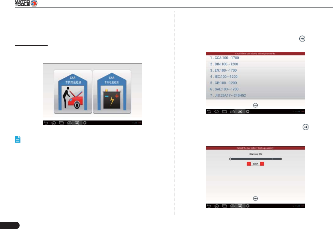
tap [OK], the system will continue the testing. Tap , it will enter
testing standard selection screen. See Fig. 7-5.
Fig. 7-5
Select a testing standard except for JIS and tap 6. , a screen
similar to Fig. 7-6 will appear. Users can adjust capacity size by
tapping on < or > or by dragging the slider on the bar.
Fig. 7-6
MAXIMUS2.0 User's Manual
33
If JIS is selected, tap , the system will enter Select testing
capacity screen. Users can select corresponding standard capacity
value according to battery model marked on battery.
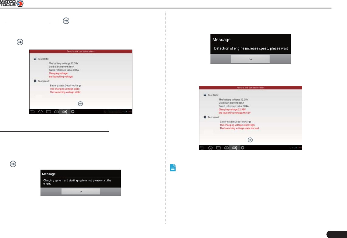
Tap 7. and the testing result will appear on the following screen.
Fig. 7-7
2. Charging system and starting system test
While performing this test, the battery’s charging voltage value
and starting voltage can be obtained in case of engine starting and
accelerating. Based on the data, the system will judge whether
battery’s charging and actuation status is normal or not.
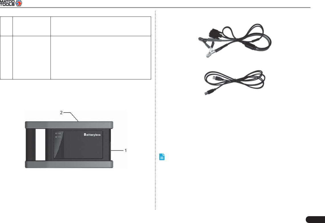
Tap in Fig. 7-7, a dialog box will pop up as Fig. 7-8.
Fig. 7-8
After detecting engine starting, follow the instructions on the screen to
increase the speed.
The system begins to receive test data information after acceleration
was detected, as shown in Fig. 7-9.
Fig. 7-9
Tap [OK], test data will be shown on the screen, similar to Fig. 7-10.
Fig. 7-10
Notes: It is unnecessary to perform charging system and start
system test after fi nishing battery test, but battery test must be done
before undergoing charging system and starting system test.
7.4.3 Outside the vehicle test
It only applies to battery test and detecting fl oating electricity will be
ignored while performing battery test.
On Fig. 7-4, tap [Outside the vehicle] to select battery test standard.

34
MAXIMUS2.0 User's Manual
The following operation steps are identical to Steps 6 ~ 7 in Chapter
7.4.2 Battery test. Please refer to it for details.
7.5 Precautions on battery test
For the purpose of getting accurate test results, unless otherwise
special required, all loads need to be power off such as headlamp,
engine etc. before testing battery.
The operating time required for charging system and actuation system
test varies from person to person. If the engine does not start or
accelerate within 30 seconds, the system will prompt you “receiving
timeout” and return to the initial status.
Whether Engine is off or not has no influence on charging and
actuation test result after increased speed is detected, but other loads
need to be powered off.
The accuracy of battery voltage, charging voltage, start voltage is
0.01V in test results; CCA (Cold Cranking Amps) precision is 5CCA.
Generally, charging voltage value is greater than starting voltage.
Charging voltage range is as follows: 13.8--14.5V for domestic vehicle;
13.3--15.5V for imported vehicles. The voltage varies with different
car models, so you have to judge based on related vehicle models.
In general, the DC voltage is stable, but it also varies with different
revolution speed.
Starting voltage range: the value higher than 9.6V is regular, otherwise
it is too low. Due to different situations, whether the starting voltage
is higher or not does not mean the vehicles or batteries are faulty.
For detailed faults, other special equipments are needed. To validate
the accuracy of the value, the best method is to collect the signals of
starting and charging voltage and observe it on an oscillometer.
Generally, the voltage is lower than 11V for the bad cell battery, but it
is possible that the battery is completely exhausted or has a serious
low capacity. In this case, just recharge your battery. Bad cell always
happens when the loads on a stopping vehicle are turned on for a long
time.
Please note that it is normal for quick detecting of “Increase speed”
because it follows the theory of detecting “Increase speed”: if the
detected voltage is higher than the previous battery test voltage, the
system will prompt you a message of “Engine has been speeded”
It has no influence on test result in the event that engine’s output
voltage or engine revolution is not very stable. No matter whether
the vehicle is accelerated or not, the output voltage only differs within
0.2V.
While doing inside the vehicle test, Kelvin clip is always found to be
in poor contact. To remain it in good contact, please shake it several
times before testing. Take down the battery connector, and test it
again, the value probably varies. The deviation may arise from battery
connector.
Pay more attention to connect the clip. The battery poles connect
with conductor, which makes the clip has a poor connection when
testing battery. A tolerance of dozens of CCA occurs if the clip is out of
position, or oil, dust attaches on the pole. The gear and main body of
clip should be fully matched with battery poles.
Notes:
Battery poles inside the vehicle are enveloped by connectors, which 1. may produce some errors for test results. The tolerance results
from the resistance of connectors. The greater the resistance value
is, the greater the tolerance becomes. But generally, the tolerance
does not affect the test conclusion.
Testing the battery separately generates an exact test result. 2. The battery box is a very useful auxiliary tool for quick test. If any
problems were found, test it separately for getting an exact test
result.

MAXIMUS2.0 User's Manual
35
8 Oscilloscope (coming soon)
Oscilloscope is an optional function of MAXIMUS2.0, including
automotive oscilloscope and automotive ignition waveform.
Automotive oscilloscope can make the auto repair technician quickly
judged the faults on automotive electronic equipment and wiring, and
the oscilloscope sweep speed is far greater than the signal frequency
of such vehicles, usually 5-10 times of the measured signal. The
automotive oscilloscope not only can quickly capture the circuit signal,
but also can slowly display the waveform to observe and analyze. It
can also record and store the tested signal waveform which can be
played back to observe for the fast signal, having great convenience
to failure analysis. Either high-speed signal (e.g.: injection nozzle,
intermittent fault signal) or the slow-speed signal (e.g. the throttle
position change and the oxygen sensor signal) can be observed
through automotive oscilloscope in an appropriate waveform.
The electronic signal can be compared and judged via measuring fi ve
parameters indexes. The fi ve parameters indexes are the amplitude
(the maximum voltage of signal), the frequency (the cycle time of
signal), the shape (the appearance of signal), the pulse width (the
duty cycle or the time range of signal), and the array (the repetition
characteristic of signal), which can be tested, displayed, saved by the
automotive oscilloscope. Via the waveform analysis can further detect
the circuit fault on sensors, actuators, circuits, and electronic control
units, etc.
9 Borescope (coming soon)
Automotive borescope is mainly applied to those unseen parts of
engine, fuel tank, braking system.
While testing a vehicle system, engine is one of the main parts to
be checked. To check if the internal of a engine is qualifi ed or not or
whether internal carbon deposit and damage exists in the engine or
not, we can make full use of a borescope to solve these quesitons.
MAXIMUS2.0 provides an optional function of borescope.
The borescope is mainly composed of an inspection camera, fl exible
tube and USB cable. The waterresistant camera lens with adjustable
LED lights enables you to observe the parts that can not be seen in
wet, dark, fl uid soaked places. The included fl exible tube is convenient
for easy inspection and allows for access to hard-to-reach areas.
In addition, the captured pictures and videos also provide you intuitive
data for easy analysis.
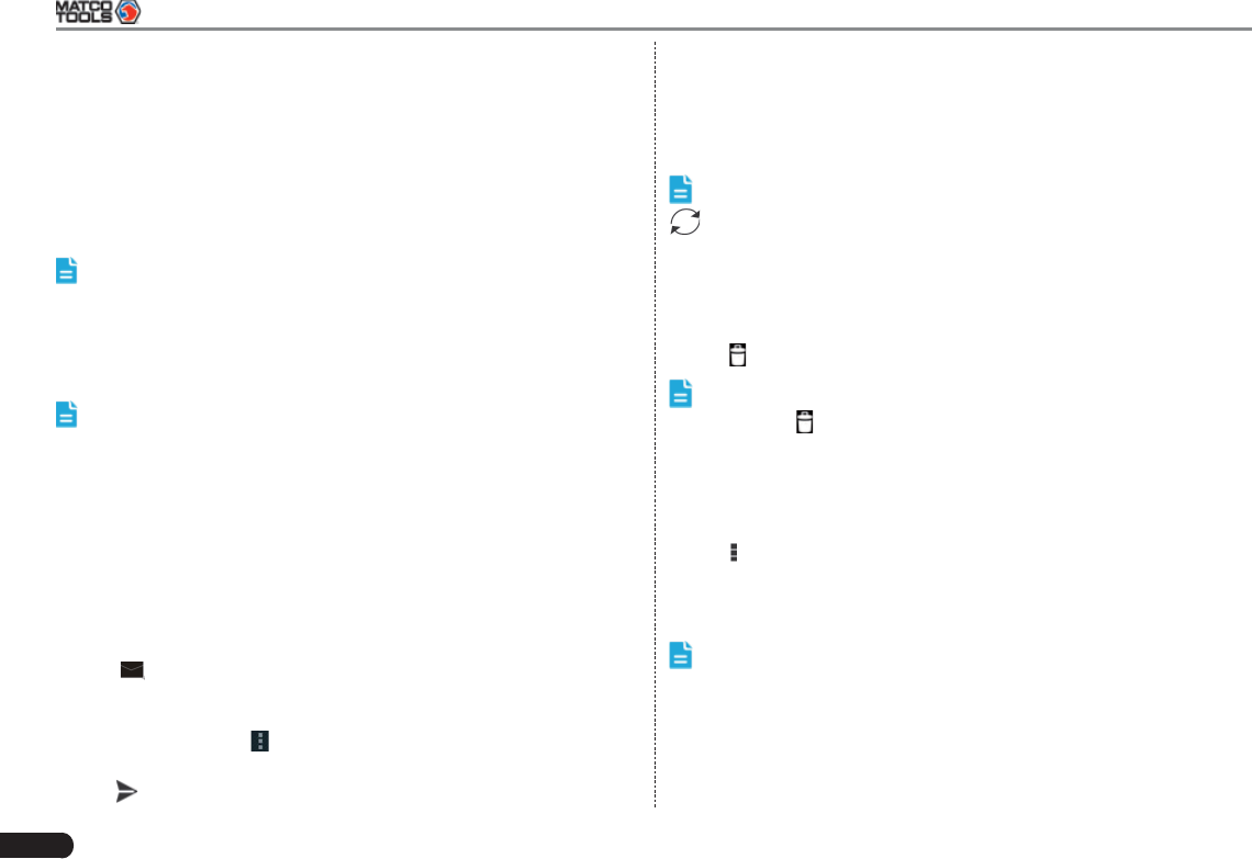
36
MAXIMUS2.0 User's Manual
10 Others
10.1 Email
The function allows you to send and receive email. You can add POP3
or IMAP email account for some common web email service provider.
10.1.1 Confi gure an email account
Note: Before sending or receiving email, you have to set up an
email account. In addition, this function required a stable network
connection.
On the desktop, click 1. Email.
Input email address and password, click “Next” or “Manual setup”. 2.
Note: If “Manual setup” is selected, please consult your email
service provider for detailed parameter setting.
Choose the desired email account type to enter the incoming 3.
settings screen, tap “Next”.
Follow the on-screen instructions to proceed until the system 4.
prompts you that the account setup has been fi nished.
10.1.2 Send an email
Enter main menu screen, and click 1. Email to enter account screen.
If several email accounts are confi gured, choose the desired one.
Tap 2. to enter new mail writing interface. Input the receiver
address in “To” fi eld and a title in “Subject” column, and then type in
the content in “Compose” email area.
After inputting, click 3. , you can perform any one of the followings:
Attach fi le, add CC/BCC, save draft, discard and setting.
Tap 4. to send email.
10.1.3 View an email
Enter main menu screen, and click 1. Email to enter account screen.
Tap the desired email account.2.
Tap the desired one to read:3.
Note: For different networks, inbox may have some delays. Tap
on the upper right corner to refresh the email list.
10.1.4 Delete an email
Enter main menu screen, and click 1. Email to enter account screen.
Tap the desired account, and then select the mail to be deleted. 2.
Tap 3. to delete.
Note: To delete multiple emails, check the box before the message
and then click . Once “Messages deleted” appear, it indicated the
selected messages has been removed successfully.
10.1.5 Revise an account setting
Enter main menu screen, and click 1. Email to enter account screen.
Tap 2. > Settings.
Choose the desired Email account from the account list.3.
Follow the instructions on the screen to make general settings and 4.
notifi cation settings.
Note: Never change the default settings of the server, otherwise
email failure may occur.
10.1.6 Delete an email account
Once Email account is removed, MAXIMUS2.0 stops receiving the
emails from this account, but all messages in it still keeps as it is.
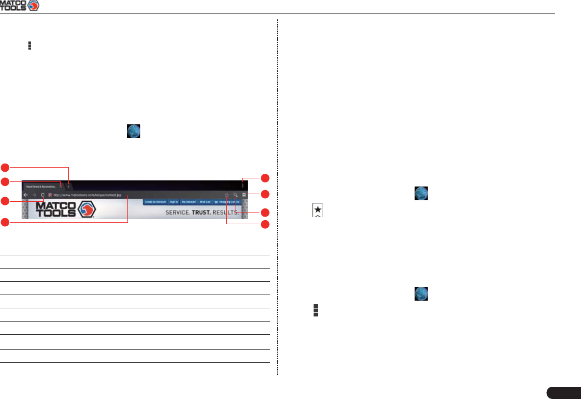
MAXIMUS2.0 User's Manual
37
Enter main menu screen, and tap “Email” to enter account screen.1.
Tap 2. > Settings.
Choose the desired Email account from the account list.3.
Choose “Remove account” to delete it.4.
10.2 Browser
10.2.1 Open browser
Enter main menu screen, click to launch the browser. You can
choose the desired homepage or input the website address to browse.
1
2
3
45
6
7
8
Fig. 10-1
1Create a new tab.
2Close the current page.
3Refresh the current page.
4Input a web address.
5Add the current page as bookmark.
6Open search bar.
7Open bookmark list.
8View more options.
10.2.2 Download fi les
Files, pictures, and applications can be downloaded from the website
in browser.
For example:
Tap and press a picture, then choose “Save image” from pop-up menu
to download it.
To download a link, tap and press it, and then choose “Save link”.
To protect your MAXIMUS2.0 and personal data, please download
applications from trusted sources. To configure it, click Settings >
Security, and then deselect the box next to Unknown sources.
10.2.3 Manage bookmarks
You can set the favorite website as bookmark for your quick access.
Enter main menu screen, click 1. to launch the browser.
Tap 2. to enter bookmarks page.
Long press it, you can share, open and delete the bookmark. 3.
10.2.4 Set homepage
This option enables you to set commonly visited website as the
homepage. The homepage will be opened by default every time you
launch your browser.
Enter main menu screen, click 1. to launch the browser.
Tap 2. > Settings > General.
Tap “Set homepage”, then follow the on-screen instructions to fi nish 3.
it.
10.2.5 Clear history
To prevent your personal information from being exposed much better,
38
MAXIMUS2.0 User's Manual
you are strongly recommended to clear your browser navigation
history.
Enter main menu screen, click 1. to launch the browser.
Tap 2. > Settings > Privacy & security.
Tap “Clear history”.3.
10.3 Using Bluetooth
Bluetooth connection is supported on MAXIMUS2.0. Using it, you
can connect MAXIMUS2.0 to other compatible devices for data
transmission.
Note: Bluetooth connection is likely to be disturbed by other
objects, such as walls or other electronic devices.
10.3.1 Open Bluetooth
Enter main menu screen, click “Settings” --> “Bluetooth”. 1.
When the Bluetooth switch is ON position, it indicates it is already 2.
on and a corresponding Bluetooth icon will appear on the status bar
of MAXIMUS2.0.
10.3.2 Allow other devices to search for MAXIMUS2.0
Enter main menu screen, click “Settings” --> “Bluetooth”. Tap 1.
and choose “Visibility timeout”.
Set the desired visibility option.2.
10.3.3 Search other devices and pair MAXIMUS2.0 with it
Before transmitting data with other Bluetooth devices, you have to pair
MAXIMUS2.0 with it.
Check and ensure Bluetooth is ON. 1.
Enter main menu screen, click “Settings” --> “Bluetooth”.2.
MAXIMUS2.0 starts scanning all Bluetooth devices. 3.
Choose the desired one from the search result to pair it with 4.
MAXIMUS2.0.
10.3.4 Send fi le via Bluetooth
You can send pictures, videos, audio fi les or test reports to others for
sharing and review via Bluetooth.
To transfer files via Bluetooth, please proceed following the steps
described below:
Enter main menu screen, and click “File Manager”.1.
Access the corresponding folder and choose the desired picture, 2.
video or audio fi le.
Tap 3. and choose “Bluetooth” from the pull-down menu.
Tap the target Bluetooth device you want to transmit fi les. 4.
10.4 Camera
10.4.1 How to take a picture
Enter main menu screen, click .
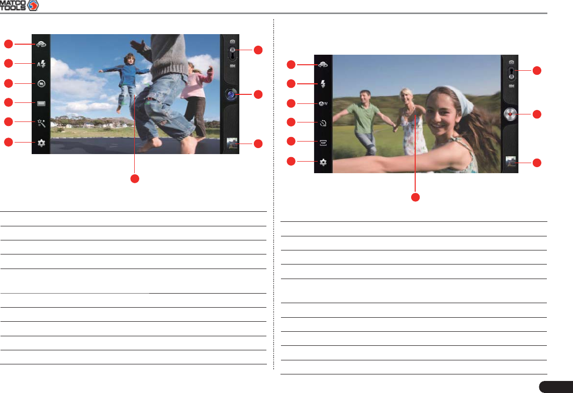
MAXIMUS2.0 User's Manual
39
1
10
9
8
7
6
5
4
2
3
Fig. 10-2
1 Drag the slider to toggle between camera and video mode.
2 Tap it to take a picture.
3 Tap it to browse your pictures.
4 Slide to right or left to zoom in/out the screen.
5 Set camera parameters, such as Exposure, White
balance, Picture size etc.
6 Tap it to select color effect.
7 Tap it to set snap mode: Normal or Panorama Snap.
8 Tap it to set continuous snap mode: Normal or Fast Snap.
9 Tap it to turn on/off fl ash mode.
10 Tap to toggle between front camera and rear camera.
10.4.2 How to record a video
In camera mode, drag the slider to video mode.
1
10
9
8
7
6
5
4
2
3
Fig. 10-3
1 Drag the slider to toggle between camera and video mode.
2 Tap it to start recording a video.
3 Tap it to play back your video.
4 Slide to right or left to zoom in/out the screen.
5 Tap it to make some video settings, including Fix time,
Exposure, Save location etc.
6 Tap it to choose video size.
7 Tap it to set time lapse interval.
8 Tap it to set white balance.
9 Tap it to turn on/off fl ash mode.
10 Tap to toggle between front camera and rear camera.
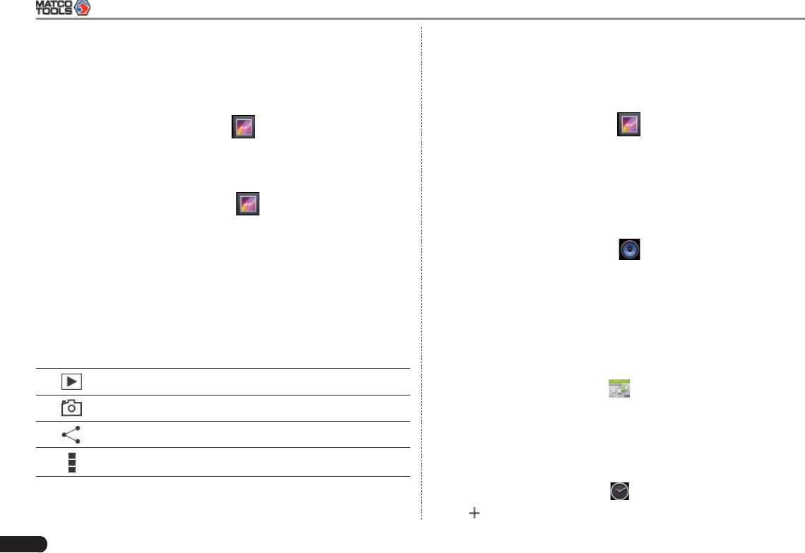
40
MAXIMUS2.0 User's Manual
10.5 Gallery
This option is used to manage pictures and video fi les.
10.5.1 Open gallery
Enter the main menu screen, click to open gallery, the system
starts scanning all pictures and videos on MAXIMUS2.0.
10.5.2 View pictures or videos
Enter the main menu screen, click 1. to open gallery.
Tap a picture or video fi le to view it in full screen mode. Swipe the 2.
screen to right or left to view the previous or next one.
To zoom in manually, place two fi ngers on the screen and then spread
them apart. To zoom out, either double-tap again or place two fi ngers
apart on the screen and then pinch them together.
Featuring gravity sensor, MAXIMUS2.0 will adjust the orientation of
the pictures automatically if it is rotated.
The following operations can be also done while browsing gallery:
To play back pictures in the current folder.
To launch camera.
To share pictures or videos.
To view more options.
10.5.3 Edit photos
Without installing third-party photo processing software, MAXIMUS2.0
provides powerful photo editing functions, such as light compensation,
red eye processing, crops etc.
Open the picture to be edited in 1. .
Tap the icons located on the bottom of the piture to perform the 2.
corresponding functions.
Tap Save, the edited picture will also be saved in the same folder in 3.
which the original picture lies.
10.6 Music
Enter main menu screen, and click to enter. Music fi les are stored
into 4 categories: Artists, Albums, Folders and Playlist.
Tap the desired music type. Open music fi le list.1.
Tap the desired audio fi les to start playing. 2.
10.7 Calendar
This function lets you view calendar or create to-do events.
Enter main menu screen, click . Tap the time in the upper left
corner to switch between Day, Week, Month and Agenda.
10.8 Alarms
10.8.1 Add an alarm
Enter main menu screen, click 1. .
Tap 2. to enter new alarm setting interface.
MAXIMUS2.0 User's Manual
41
Set the detailed items. 3.
After setting, click “OK” to confi rm.4.
10.8.2 Delete an alarm
On alarm list screen, hold and press the desired alarm.1.
Tap the 2. , and then tap “OK” in the confirmation dialog box to
delete it.
10.8.3 Turn on/off alarm
On alarm list screen, slide the switch to ON to activate it. To disable it,
just switch it to OFF.
10.9 File Manager
This option enables you to manage your fi les.
Tap File Manager, and then choose the desired folder to perform
corresponding operations.
10.10 Applications
10.10.1 Install applications
To install an application, you need to download it firstly. All items
downloaded in default browser are saved in Downloads.
On the main menu screen, click 1. Downloads.
Choose the desired .apk fi le.2.
Tap “Install” to start installing the application.3.
Tap “Done” to fi nish it.4.
Note: In process of installation, a message prompting installation
prohibited may appear. Please read it carefully. To install it, please tap
“Settings” > “Security”, and check the box next to “Unknown sources”,
which allows you to install non-Market application.
10.10.2 View installed applications
Tap Settings > Apps.1.
Swipe the screen from right to left until ALL tab appears. 2.
Tap the desired one to view its detailed information.3.
10.10.3 Uninstall applications
To release storage space, you can uninstall some unused applications.
Tap Settings > Apps.1.
Swipe the screen from right to left until ALL tab appears. 2.
Tap the desired one to enter.3.
Tap “Uninstall” and then tap “OK” in the dialog box to start 4.
uninstalling.
10.11 Set Date & Time
MAXIMUS2.0 is preset to use the network-provided date, time zone
and time.
Note: If Automatic date & time is set as Use network-provided
time, date, time and time zone will not be defi ned.
Enter the main menu screen, tap Settings > “Date & time”.1.
Deselect “Automatic date & time”.2.
Follow the on-screen instructions to set date, time and time zone. 3.
10.12 Clear Cache
If insufficient memory occurs, please clear cache to spare more
storage space.
42
MAXIMUS2.0 User's Manual
Tap Settings > Apps.1.
Swipe the screen from right to left until ALL tab appears. 2.
Tap “Clear cache”.3.
11 FAQ
1. How to save power?
Please turn off the screen while MAXIMUS2.0 keeps idle.•
Set a shorter standby time.•
Decrease the brightness of the screen.•
Try to use earphone.•
Please turn off Bluetooth when it’s not in use.•
If Wi-Fi connection is not required, please turn it off.•
Disable GPS function if GPS service is not in use.•
2. What should I do in case I forgot the screen lock?
You can set screen lock as pattern or password. If you forgot the
password, please consult your device provider or reset your device.
Warning: Resetting may cause data loss. Before use, please
make sure important data has been backed up.
3. How to do if the system runs slowly?
In this case, please do the followings:
> Check all running applications and stop the unused applications.
> Check all installed applications and remove the unnecessary
applications.
If all steps mentioned above are fi nished and the system still works
slowly. Please try to close the system and reboot your MAXIMUS2.0.
4. How to format internal storage?
On the main menu screen, tap Settings.1.
Tap “Storage” > “Erase internal storage” to enter and confi rm your 2.
operation.
MAXIMUS2.0 User's Manual
43
Warning: Doing so will erase all stored data and all running
applications may encounter abnormal operations. To restore it, just
restart your MAXIMUS2.0.
5. Why some videos on the website can be not played?
It possibly results from:
The current browser does not support Flash playing; 1.
Flash player does not support this video. 2.
Try to use other browsers to watch it or install other Flash player.
6. The data and time of MAXIMUS2.0 can not be set.
It is because Automatic date & time is set on your MAXIMUS2.0. Tap
Settings > Date & time, deselect “Automatic date & time” and then set
the date and time manually.
7. How to distinguish between PIN and password in screen lock?
The difference between PIN and password is as follows:
> PIN: Generally, it is composed of 4~16 numbers.
> Password: it may include: 4~16 numbers, characters and symbols.
Customer Service Department
If you have any questions on the operation of the unit, please contact
us: 1-877-LAUNCH-9
Statement:
LAUNCH reserves the rights to make any change to product designs
and specifi cations without notice. The actual object may differ a little
from the descriptions in the manual in physical appearance, color
and configuration. We have tried our best to make the descriptions
and illustrations in the manual as accurate as possible, and defects
are inevitable, if you have any question, please contact local dealer
or after-sale service center of LAUNCH, LAUNCH does not bear any
responsibility arising from misunderstandings.
Note: This equipment has been tested and found to comply with the limits for a Class
B digital device, pursuant to part 15 of the FCC Rules. These limits are designed to
provide reasonable protection against harmful interference in a residential installation.
This equipment generates uses and can radiate radio frequency energy and, if not
installed and used in accordance with the instructions, may cause harmful interference
to radio communications. However, there is no guarantee that interference will not
occur in a particular installation. If this equipment does cause harmful interference to
radio or television reception, which can be determined by turning the equipment off
and on, the user is encouraged to try to correct the interference by one or more of the
following measures:
-Reorient or relocate the receiving antenna.
-Increase the separation between theequipment and receiver.
-Connect the equipment into an outlet on a circuit different from that to which the
receiver is connected.
-Consult the dealer or an experienced radio/TV technician for help.
Any Changes or modifications not expressly approved by the party responsible for
compliance could void the user's authority to operate the equipment.
FCC RF Radiation Exposure and SAR Statements
The exposure standard for wireless devices employs a unit of measurement
known as the Specific Absorption Rate(SAR). The SAR limit set by the FCC is
1.6 W/kg. The highest SAR level measured for this device is 0.112W/kg<1.6W/kg,
so this device meets the FCC Requirement.