Leadtek Research LR3616 Wireless Surveillance Camera 3616 User Manual
Leadtek Research Inc Wireless Surveillance Camera 3616 Users Manual
Users Manual

EADTEK
ideo Surveillance
MOS
Network Camera Series
Network Surveillance Camera 3615
&
Wireless Surveillance Camera 3616
User Manual
L
V
C

2
echnical Support
Technical Support provides services of Leadtek Research Inc. video surveillance
product series, including latest firmware/software upgrade, camera lens introduction,
PT rotating controls. Technical Support will also assist customers with the product
installation, hardware and configuration trouble-shooting.
Please visit the website below or mail us via the email address.
Web site: www.leadtek.com
Email: service_ipcam@leadtek.com
arranty Information
No parts of this document may be copied or reproduced in any form or by any means
without the prior written consent of Leadtek Research Inc.
Leadtek makes no warranties with respect to this documentation and disclaims any
implied warranties of merchantability, quality, or fitness for any particular purpose. The
information in this document is subject to change without notice. Leadtek reserves the
right to make revisions to this publication without obligation to notify any person or entity
of any such changes.
Provide the following information when warranty repair is required:
1. Model name and production serial number (label begins with a ¡L¡)
2. Date of shipment, P.O. number, sales order number, Leadtek corporation invoice
number.
3. Detail description for product issues encountered .
Trademarks or brand names mentioned herein are trademarks or registered
T
W
Technical Support and Warranty Information
3
trademarks of their respective owners.
Copyright 2008 Leadtek Research Inc. All rights reserved
International Headquarters
18th Fl., 166, Chien-Yi Rd., Chung Ho, Taipei Hsien, Taiwan (235)
Phone: +886 (0)2 8226 5800
Fax: +886 (0)2 8226 5801

4
Product Features
6
Overview - NSC 3615 7
- WSC 3616 8
Interface 9
System
Requirement 9
Introduction 10
Configure the
Network Camera
- Start 11
- ActiveX Viewer 11
Login the
Network Camera
- IPCAM Discoverer 12
- Internet Explorer 13
Web Layout 14
- System 15
* SIP 16
* APS 17
* Others 17
* DIDO 19
* Surveillance
Password 20
- Network 21
* IP 21
* FTP 22
* SMTP 23
Table of contents

5
* DDNS 24
* Port Setting 25
- Wireless 26
- Camera 27
* Camera 27
* Encode Type
28
* Call To 29
User
Management 30
System
Information 31
System Log 32
Appendix 33
FAQs 38
Warning 40

6
roduct Features
Network Camera can help you to view live surveillance video/audio over
Ethernet/Internet. With its compact color CMOS lens 1.3Mega Pixel, MPEG-4/H.263
video and G.711/G.729 audio compression, built-in microphone, two-way audio
communication with SIP protocol, the in-time monitoring can be flexibly extended to the
Telephony world, such as interoperated with Video Phone/3G mobile etc.
Key Features
Compact Color CMOS (1.3M pixel)
MPEG-4, H.263 video and G.711/G.729 audio compression
JPEG capture via Motion Detection
Internet connection compatible with Ethernet
Built-in web server for remote management
Bundled VoIP software client SoftPhoneR for portable communication
Bundled NETCAM management software client for remotely use
Inter-operation with Video Phone
Two-way audio transmission
Flexible installation solution
802.11b/g for WIFI standards
P
Product Features
7
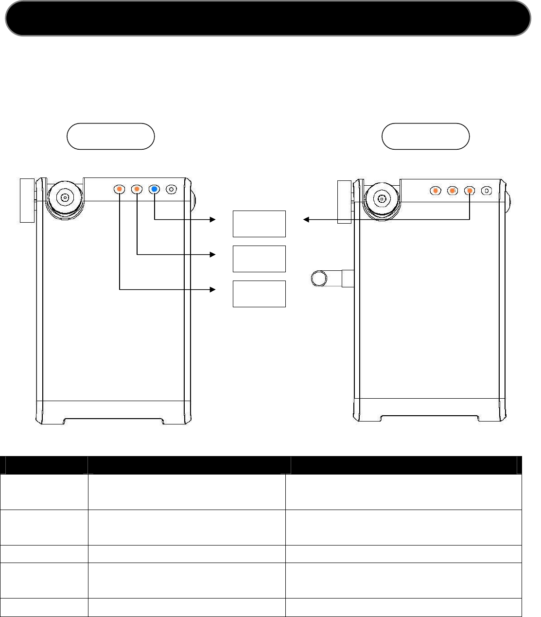
VerView Network Surveillance Camera 3615
O
Product Features
Network Indicator LED
Internal Microphone
External Microphone
Camera Rotate Switch
CMOS Lens
Network
Connector
Audio Out
Power
Connector
I/O terminal
Connector
Reset Button
Restore Default Button
Access Incoming Indicator LED
SIP Registration Status Indicator LED

8
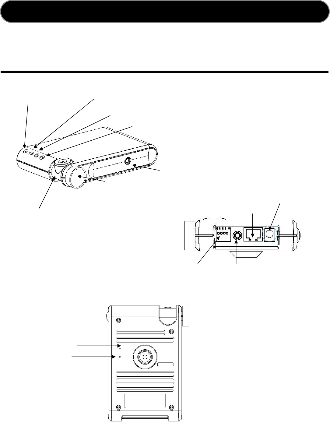
verView Wireless Network Surveillance Camera 3616
O
Product Features
Reset Button
Restore Default Button
Network
Connector
Audio Out
Power
Connector
I/O terminal
Connector
Antenna Connector
Network Indicator LED
Internal Microphone
External Microphone
Camera Rotate Switch
CMOS Lens
Access Incoming Indicator LED
SIP Registration Status Indicator LED
Antenna

9
nterface Connector
Network connector ¡ RJ-45 Ethernet Connector
Antenna connector ¡ 2.0 dbi external swivel Antenna for transmitter and receiver
Power connector ¡ DC connector 3- 5V DC, 2.5A max 10W
Build-in Microphone ¡ 5M, Omni directional
External Microphone ¡ 3.5mm mono earphone jack
Audio out ¡ mono jack output, 50mW PC compatible
I/O terminal connector ¡ alarm, motion, event triggering notification
LED Indicator ¡ indicators show as follows:
ystem Requirement
Operation System Windows 2000, XP SP2, Windows Vista
CPU Intel Pentium 4 2 GHz equivalent processor, 512MB RAM
Network Protocol TCP/IP, PPPoE, DHCP, Static IP, DDNS, SMTP, FTP, NTP
Web Browser Internet Explorer 6.0 or higher, Firefox
Ethernet Interface 10/100 Mbps Ethernet Card for network connection
Others CD-ROM/DVD, Video card supports 32-bit color, 80G HDD
I
LED Color Indication
Network
Blue 10/100Mbit/s LAN network connection activity.
Amber Wireless network connection activity.
Unlit No network connection.
Access Flashes
Subscriber Incoming Entry.
Unlit No connection.
SIP Amber SIP Registration Successfully.
Flashes
SIP Registration Failure.
Flashes
Both of amber indicator flashes for upgrade status.
S
Product Interface

10
High-quality, High efficiency video & audio transmission via IP network
The network surveillance camera allows you to view live video over internet. Your control center can
be set up anywhere with internet access without being restricted by locations. Surveillance video is
processed by the most up-to date compression technology and transmitted in MPEG-4 compression
format, whose transmission efficiency and video quality remain uncompromised by the network,
minimizing the lagging of live surveillance video. In addition, wireless LAN is also supported. The
wireless model makes the network usage more handy without the hassle of cable installation.
Great usability in every surveillance aspect
The network surveillance camera¡s ease of use begins with its web-based user interface, using
Microsoft Internet Explorer to browse the live video or the provided Windows client Surveillance
Management Center (SMC) that offers many additional benefits: its user interface can display video up
to 9 camera servers at the same time. Recording can also be done simultaneously and you can use it
to view recorded video from the archive and backup your recorded file with audio.
Unparalleled surveillance functions where nothing slips through your watch
The network surveillance camera¡s motion detection function sends out the alarm when any
movement of any object occurring on the scene is detected, which makes it ideal for home and
after-hour facility security. 16 preset positions can be programmed and the auto-cruise function will
make the tour accordingly as if you were taking the patrol rounds in person.
You can also program the cameras to take snapshots or record video when the alarm is triggered by
the event. These snapshots can be transmitted via FTP or email. Event recording is done by a client
PC on the network as the camera sends snapshot in JPEG format as part of the responses to the
triggered event.
Optional centralized management software for large scale surveillance services
The software suite performs as a central control station on a client PC that controls, manages, and
monitors up to 9 network surveillance camera server units over the network at the same time. You can
talk to your surveillance camera just by a click on the managed camera to start 2-way audio
conversation. The flexible and diversified SMC offer you handy surveillance solution on Windows
platform.
Introduction

11
tart
Leadtek Network Surveillance Camera can be used on the most standard/popular
operation system and internet browsers. We recommend that Microsoft Internet
Explorer on windows and Mozilla Firefox on other operating system , such as
Mac/Linux .
ActiveX Viewer
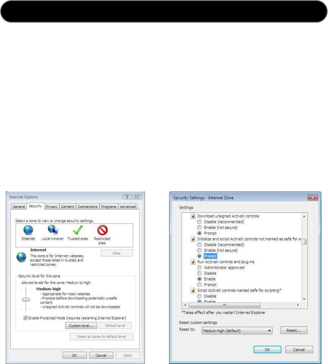
1. Launch the Internet Explorer and click ¡Tools¡ and select ¡Internet Options¡
option from the drop-down menu.
2. Click the ¡Security¡ tab from ¡Internet Options¡ .
3. Click ¡Custom Level¡ button to open the ¡Security Setting¡ .
4. Tick ¡Prompt¡ from the options titled with ¡Download signed ActiveX
controls¡ and ¡Download unsigned ActiveX controls¡ .
5. Tick ¡Enable¡ from the options titled with ¡Initialize and script ActiveX
controls not marked as safe¡ , ¡Run ActiveX controls and plug -ins¡ and
¡Scri pt ActiveX controls marked safe for scripting¡ .
6. Click ¡OK¡ to accept the modification.
7. You will see the warning message prompts out for your confirmation. Just click
¡Yes¡ to apply the modified security settings
Configure the Network Camera
The simplest way to locate a Leadtek Surveillance Camera in network is to use the
Leadtek utility program. It can scan the local network for all Leadtek cameras and helps
users for configuring the network. If you are not going to use DHCP server to
automatically assign the cameras unique IP addresses, you will need to manually
assign the camera with static IP address using the camera utility program.
S
Configure the Network Camera
12
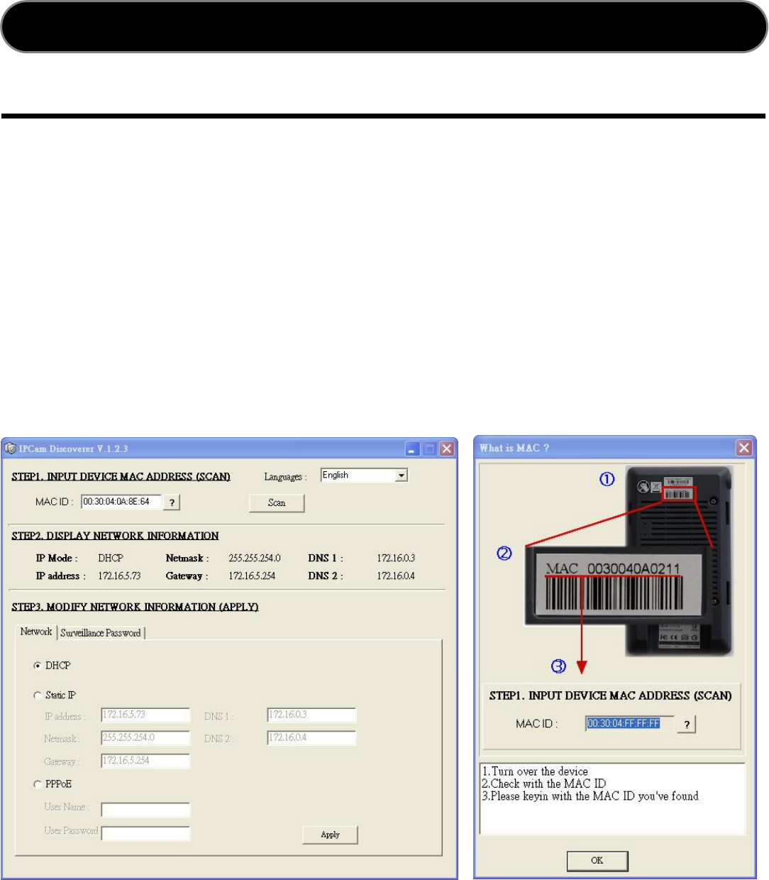
Method I. The Utility Program ¡ IPCam Discoverer
IPCAM Discoverer is an application that can help on detecting the network cameras
and then you can use PC/Notebook to connect to the cameras on network .
1. Insert the packing CD into the CD-ROM drive from your PC.
2. Install the ¡IPCam Utility Setup.exe¡ and execute it.
3. The ¡IPCam Discoverer¡ window displays and just input the ¡MAC ID¡ from the
label at bottom side. Click the ¡Scan¡ button to start searching cameras.
4. Modify the related fields while the information displays.
5. Click ¡Apply¡ to confirm the modification and re-start the Camera.
Configure the Network Camera

13
Method II. Internet Explorer Address Bar
Another way to connect the network camera is to visit with static IP address. Login the
network camera by directly entering the IP address at the IE Address Bar.
1. Manually assign the last digit (192.168.0.x , 0<x<255 & x is not equal to 100) of
your PC IP address field. Restore the network camera to set the default IP
address as 192.168.0.100.
2. Start up the internet Explorer, and enter the IP address of the Network Camera at
the address, then press ¡Enter¡ to open the system login page.
3. The camera system login page displays.
4. Enter the ¡admin¡ for both user name and password fields.
5. Video will display after the ActiveX controls downloaded and installed completed.
6. Video is displayed in Web browser as below.
Notes: When the first time login Network Camera , please set the browser to allow
ActiveX controls and Windows Firewall security alert message. You may be
requested to install ActiveX controls.
Configure the Network Camera
14
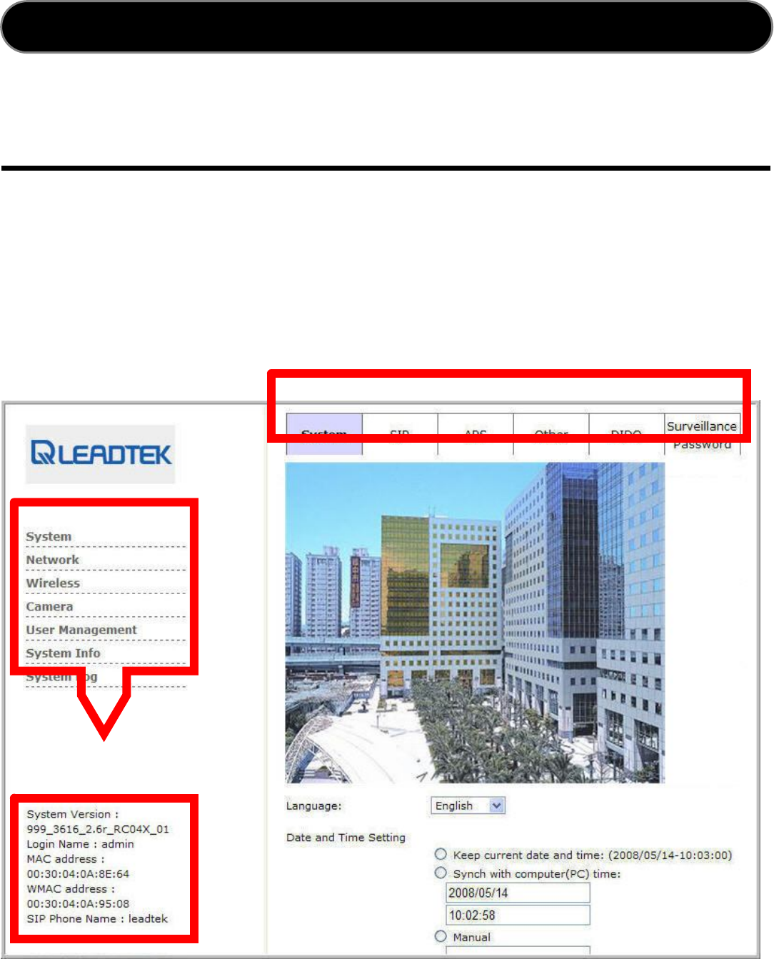
eb Layout
Network camera can be accessed and modified via browser. The webpage provided the
image view from the camera and function link on the left.
Select the main menu on the left side of the screen to enter the sub-menus.
A. Main menu
B. Sub-Menu
C. System Information
W
Web GUI
A
B
C

15
System
Language
Users may change the webpage interface language for better using Network Camera.
Just click on the language selection option, all supported languages will be shown in the
drop-down list. For the different languages, users can choose from following options.
Date / Time Setting
You may refer to the date/time settings to synchronize Network Camera¡s date/time with
Network Time Protocol (NTP) server and change the time zone as well.
Change the Date/time fields to fit required. Click SAVE button to reserve the
modifications.
English Japanese French Spanish
Big5 Gb2312 German
Keep current date and time Internal real-time clock maintains the date and time
Sync with computer time Synchronize the date and time with local computer
Manual According to enter by the administrator
Automatic Synchronize with NTP server whenever camera start up
NTP server Assign the IP address or domain name of time server
Time zone Adjust the time of the time server for local settings
Web GUI

16
SIP
SIP Configuration
Network protocol used for VOIP (Voice over IP) telephony.
SIP Register Enable to register automatically with a registry server
SIP Server SIP proxy or redirect server that provides location services
Server Port The supplied default for parameter 5060
Register Timer The supplied default parameter is 3600 (seconds)
Domain Name Registration of server domain name
Proxy Domain Setup DNS records for the proxy server domain
DNS SRV Service record I the DNS server
SIP Phone Name Configure to the VOIP provider¡s phone name
IP Cam SIP Port The supplied default for parameter 5060
User Name SIP authorization username
Password SIP authorization password
STUN Detect Enable to allow detection of NAT behavior
STUN Server IP Helps to bypass firewall or Network address translation
STUIN Server Port The supplied default for parameter 3478
STUN Enable HB Enable to contact for NAT mapping discovery
STUN HB Interval The supplied default for parameter 30
Use NAT WAN IP and
Mapped Port
Find the WAN IP address of your router, NAT should have port mapping for
different private IP address to one public.
WAN IP Address The external WAN-IP address of the router
WAN Mapped Port Address of the router and mapped ports of camera to the WAN IP address
Web GUI
17
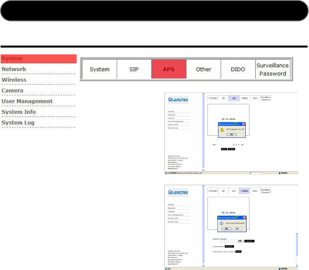
APS
APS Configuration
Auto Provision System purpose is provided
device specify configuration and account info
from the provider.
Click to ¡System¡ ¡APS¡ , and set
the options ¡ ON¡ to enable APS.
Click to ¡ System¡ ¡ Other¡ , and
press the ¡ Execute¡ button to reboot
for settings taken effect.
NOTE:
Ensure that your network environment could connect to the Internet.
During the downloading process, both amber LEDs will flash to show it was in the process.
This process may take 20 to 30 seconds which depends on Internet traffic situation.
After process finished, both amber LEDs will be off.
Please reboot the WinFast CarePhoneR for the full function working properly after APS
process finished.
Network Camera will download the customized configuration files, and the detail will be
displayed in SIP page.
Web GUI
18
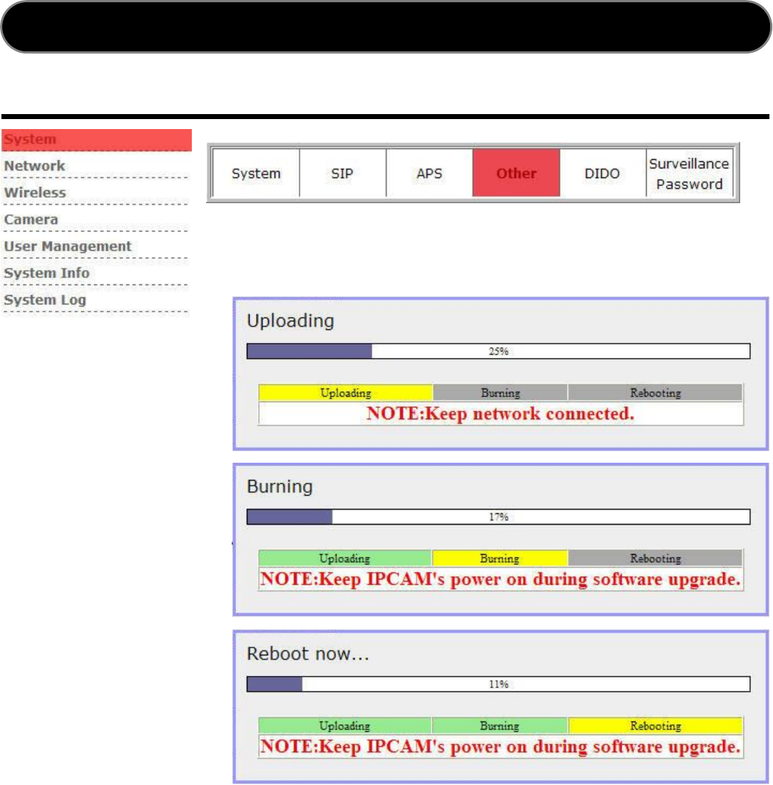
Firmware Upgrade
Upgrade
1.Click the ¡Browse¡
button and locate the file
of new firmware.
2.Click the ¡Upgrade¡
button to begin the
upgrade procedure.
System Reboot
Click the ¡Execute¡ button to restart Network Camera Device.
Reset Data to Factory Default
Click the ¡Initial¡ button to restore settings to factory default.
Web GUI
19
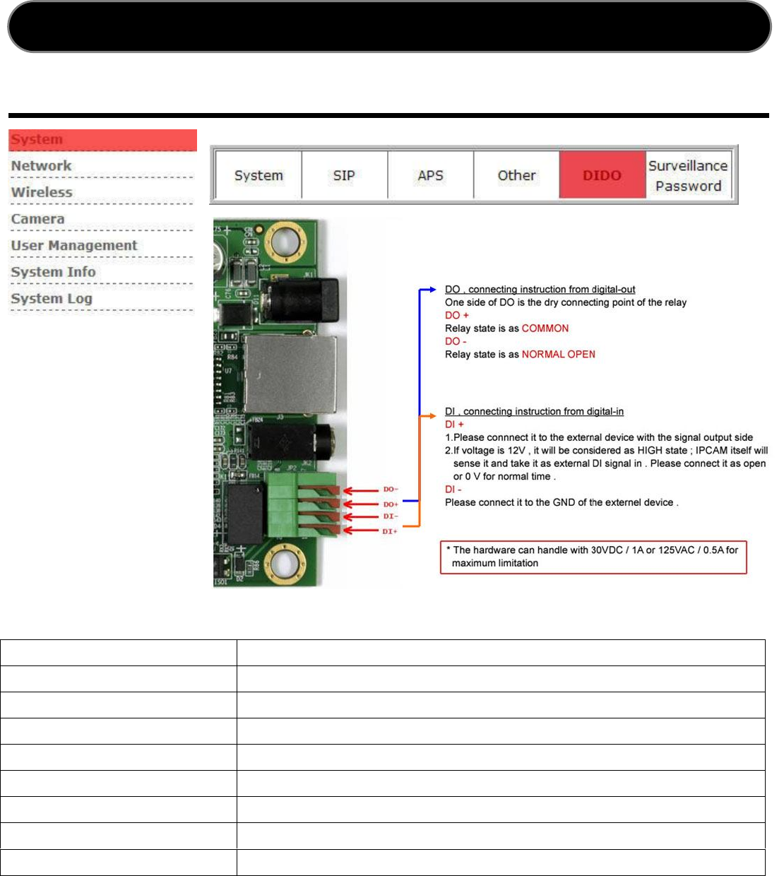
DIDO
DIDO
Configuration
DI Enable Enable terminal block
DI Type Trigger for 2 types
IM Notify IP Send message to specify IP address
IM Notify Phone number Send message to specify registry sip server phone number
IM Notify Enable Notification
SMTP Send Send Notification by SMTP
FTP Send Send notification by FTP
DO Type Normal status is Open, current status is normal
DO Notify Enable DO Notification
Web GUI
20
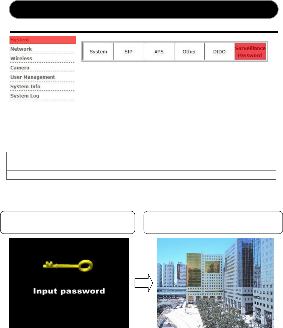
Surveillance Password
Surveillance Password Configuration
The password will help to permit authorized accesses.
Enable Password
Enable to allow you have Encryption Privacy Picture function
Input Password
The supplied default parameter is ¡12345¡ ,Numeral Only.
Confirm Password
Re-type the Password for confirmation
Web GUI
Video with password protected Video without password protected
21
Network
Network Type
The Network Sub-Menu is for you to configure all network related settings.
NSC3615/WSC3616 network default type is Local LAN. Any modification will restart the
system to take effect. Make sure of each field is filled correctly before rebooting the
machine.
DHCP
Dispatch the IP address automatically from DHCP server or featured router.
Static IP
Disable DHCP dispatching feature and assign static IP address manually.
PPPoE
Select PPPoE if using ADSL. Enter your account ID and password to appropriate fields
in PPPoE.
Web GUI
22
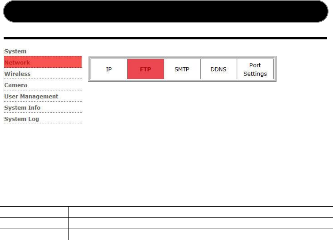
FTP
FTP Service Setup
When FTP service is enabled, camera sends a still image to the FTP server every time
the alarm triggered.
Server Name
Enter FTP server IP address or Domain Name
Login Name
The username to login the FTP server
Login Password
The password to login the FTP server
Web GUI
23
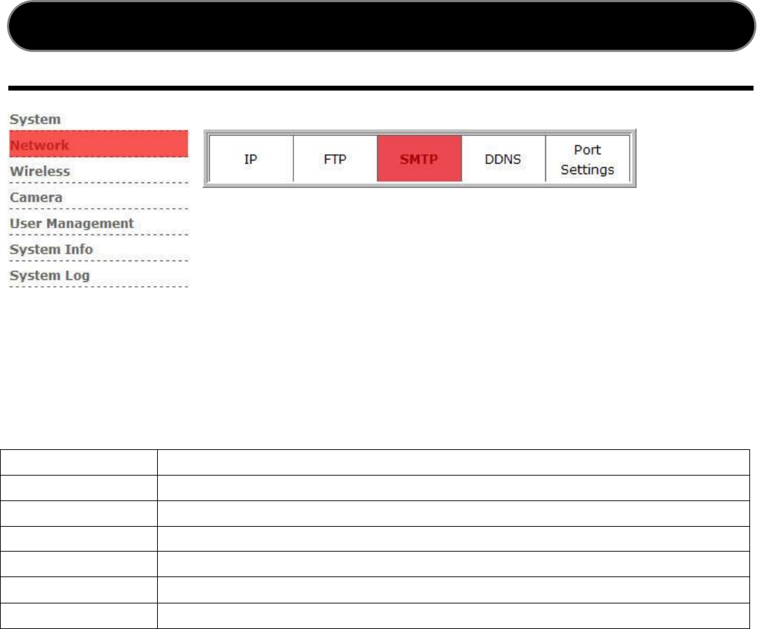
SMTP
SMTP Service
When SMTP service is enabled, the camera sends a still image to a specific email
address every time the alarm triggered.
Server Name
Enter the mail server to send the email (POP3 Server)
Login Name
Enter username that mail server required authentication
Login Password
Enter Password that mail server required authentication
Send From
Enter Personal E-mail account
Send To
Enter the E-mail account that you want to send
Title
Enter the email subject for the mail receiver recognize
Message
Provide general information in plain text
Web GUI
24
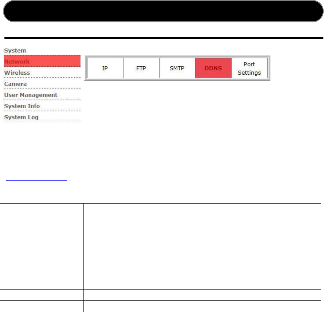
DDNS
DDNS
To find the free-of-charge DDNS service, please got to visit the DynDNS website
(www.dyndns.org) and register for a dynamic domain name which can be used to
access it over internet.
DDNS Client Enable
To use or not to use Dynamic DNS mechanism. The ISP will
dynamically allocate an IP address to your network camera, if
you dial up to internet by ADSL/Cable modem. If you want the
dynamic IP address to map to a static Domain name, you can
set the Dynamic DNS settings by enabling this feature.
Username Enter the applied username
Password Enter the applied password
Alias Alias a dynamic IP address to a static hostname
Uptimer The supplied default parameter is 1800
System ID Choose the desired DDNS server
Note: You will have to contact your internet service provider to activate a dynamic DNS
program from local execution.
Web GUI
25
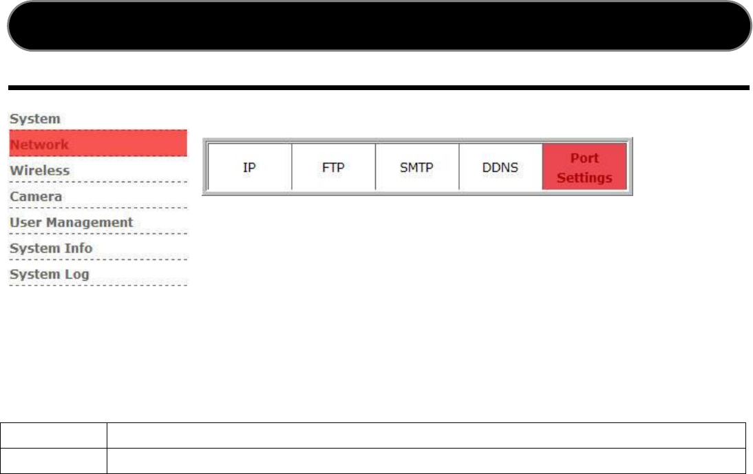
Port Setting
Port Setting
Setup the ports for data transmission from the camera on internet.
RTP Port
The supplied default port range is ¡6000 ¡ 8000¡
HTTP Port
The default HTTP port number is ¡80¡
Web GUI

26
Wireless
Wireless Configuration
Wireless Enable
Enable the Wireless mode
SSID
Specify wireless client attempting to connect a specify WLAN
Auto Mode
Setup in Auto mode
Infrastructure Mode
Setup Network Camera connect to WLAN via Access point
Ad-Hoc Mode
Setup Network Camera connect directly in peer-to-peer
Data Encryption None
No data Encryption
Data Encryption WEP
Allow communication only with other device identical WEP
Ad Hoc:
Connect the WIFI camera via PC/notebook directly, please select this mode. You must
make sure your notebook is embedded with wireless network card (for 802.11b/g
capabilities) and you must set the related parameters to 802.11b/g and Ad Hoc from
WIFI camera.
Infrastructure:
If there is a wireless Access Point, please select this mode.
Note: You may execute system rebooting after configured wireless network for validate
modification manually.
Note: This function is only available with WIFI camera.
Web GUI

27
Camera
Camera Configuration
Resolution
QCIF,CIF,VGA,D1 four kinds of resolution. Default CIF
The higher resolution will be clearer than the smaller, but it
will occupy a larger bandwidth.
Bit Rate Control
Control Enable/Disable video stream
Bit Rate
64kbps,128kbps,256kbps,384kbps,512kbps,768kbps,1M
Frame Rate
Adjust the amount of the frame per second allowable
Default 15
Brightness
The supplied parameter 1 ¡ 200. Default is 100
Contrast
The supplied parameter 1 ¡ 32. Default is 16
Saturation
The supplied parameter 1 ¡ 31. Default is 16
HUE
The supplied parameter 1 ¡ 100. Default is 50
Auto Exposure
Enable for automatic light compensation
Camera will automatically modulate white color for optimal
picture quality in any lighting condition
Color Temperature
In door range approximately 2850K ¡ 7200K
Rotation
Turns the image upside-down when mounted to ceiling
Power Frequency
Adjust the light frequency to suit your country. 60Hz is the
standard for the USA and 50Hz is the European standard
NOTE: While in darker places, raise the ¡ Brightness¡ is a recommended option.
Web GUI
28
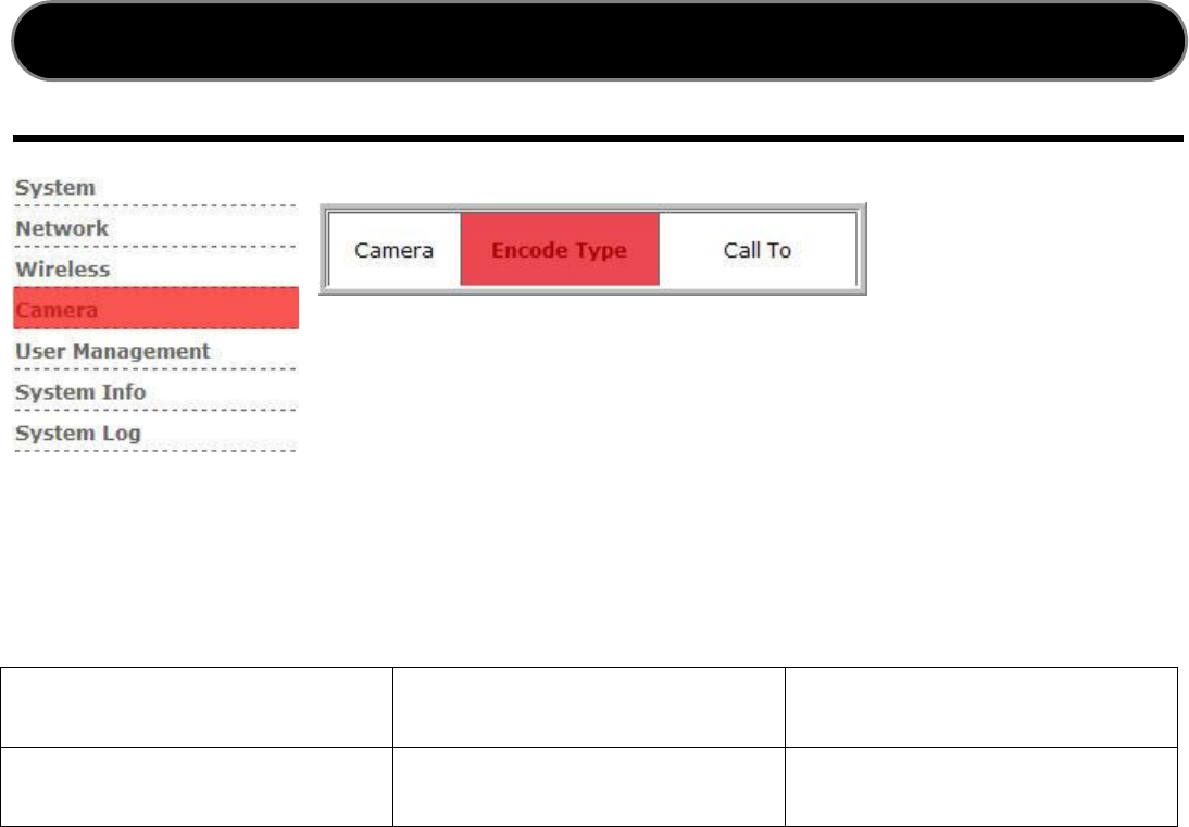
Encode Type
Encode Setting
Determine which Audio/Video codec to be streamed between client and server.
Audio Type G.711 PCMA G.711 PCMU
Video Type H.263 MPEG4
Web GUI
29
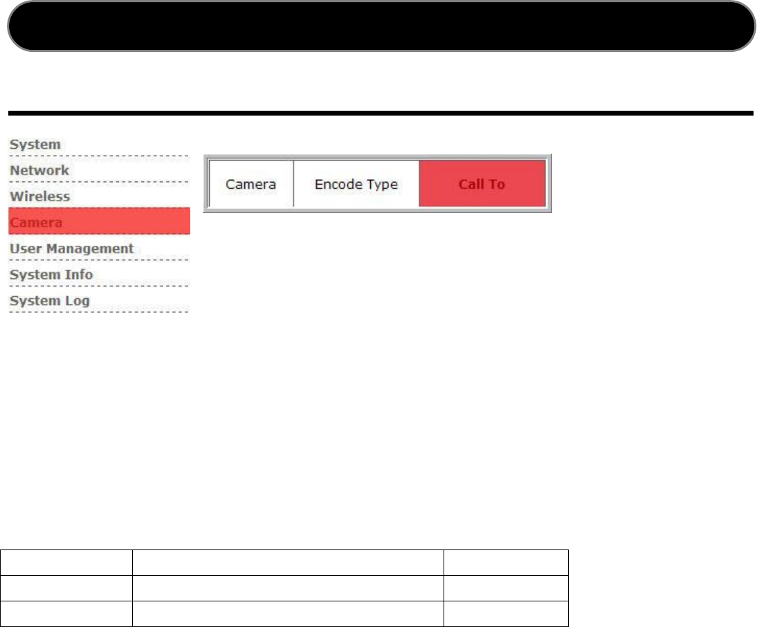
Call to
Call To
Support for all SIP proxy, peer-to-peer or SIP URL call control feature. In NSC3615/
WSC3616, only Motion Detection could trigger Call-To function. Please set related
source policy from ticking the checkbox ¡Motion Detection¡.
For viewing from mobile phone, video and audio setting encoding type should be set
first as mentioned in previous paragraph.
Detailed parameters format is as following:
Peer-to-Peer
Destination transmitted IP address
Port Number
Proxy Server
Registered SIP Phone Number Port Number
SIP URL
ResourceID@host Port Number
Source
Configure Call-to function triggered by Motion Detection or DI/DO.
Call Timeout
Configure life time for a call session to terminals.
Notify Connected PC client
Notification must be connected with PC Software application - ¡ Netcam¡ .
Web GUI
30
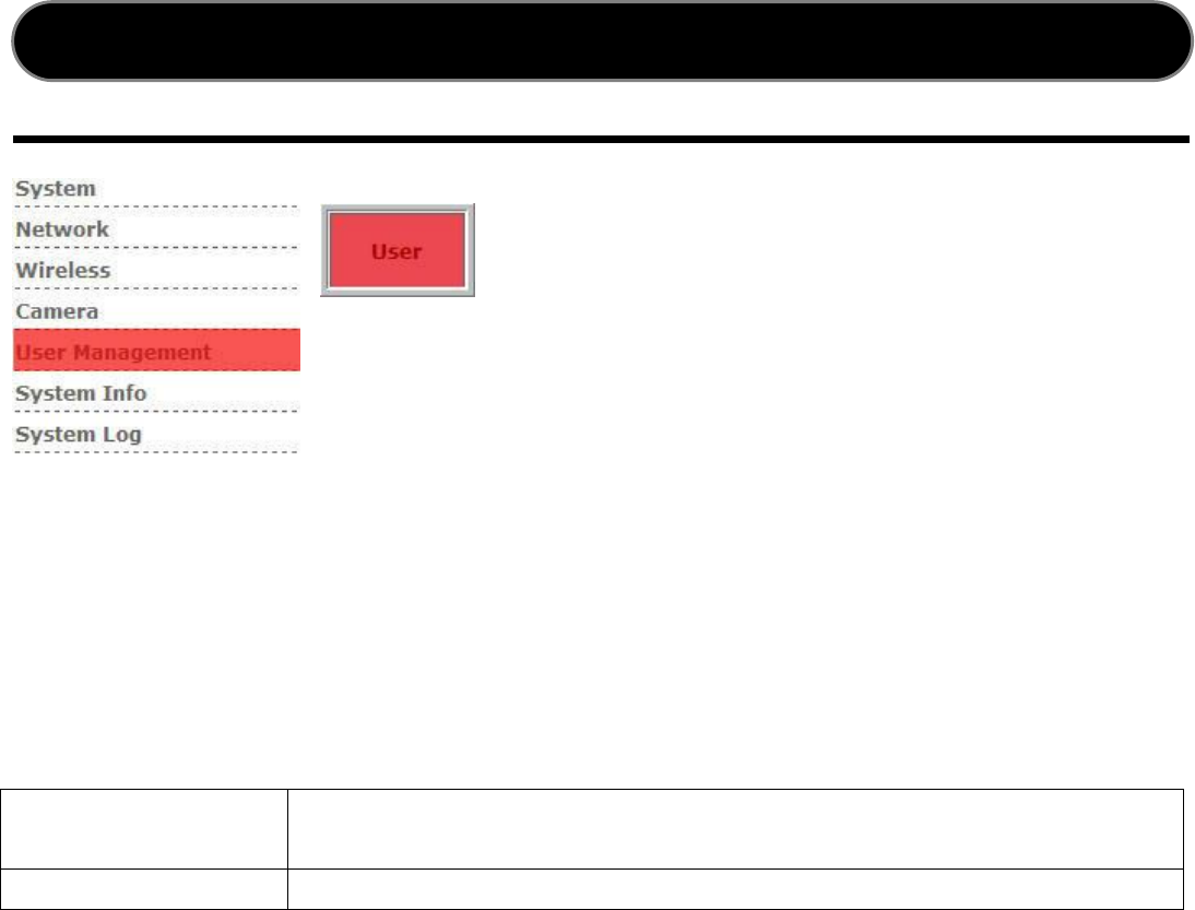
User Management
User Management
For accessing user accounts management.
Add New User
Create accounts for new users.
User ID
English and number to make up user name, less than 16
characters.
User Password
Enter Password.
User Group
The new account will be grouped with ¡ Guest¡ as default.
Guest level can only view information without any privilege to modify for any
configurations.
Delete
Click ¡ Del¡ to delete an existed user account.
Note: administrators can¡t be deleted.
Web GUI
31
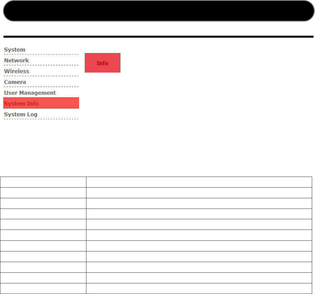
System Info
If will display with useful system information for users¡ reference, such as SIP
registration/System Uptime etc.
System Information
Model Name
Product Model Name
Firmware Version
Network Camera System Version
IPCAM ID
Product ID
IPCAM IP
Current IP address of Network Camera
Phone Number
VOIP authentication for identification
SIP Registered Status
Registry option status
SIP Registered
Registry on SIP Server statement
Online Users
The amount of observe users
System Uptime
Total uptime on Network Camera
Hardware Version
PCB Hardware Version
Sensor Version
CMOS Video Sensor Version
Web GUI

32
System Log
System Log
Shows log system time, IP status information.
Web GUI
33
LED Indicator Status
LED patterns lists table.
LED Condition Color Status
LED 1 Loading and Detecting
Network
Steady Blue till IP address is
confirmed
LED 1 Wireless Loading and
Detecting Network
Steady Amber after IP address is
confirmed
LED 2 Monitoring Video transmission Blinking Amber every second
LED2&LED3
During upgrade firmware
process
Blinking Amber every second and
Slower blink amber
LED 3 SIP registration Success Steady Amber
APPENDIX
LED 1
LED 2
LED 3
NSC3615
WSC3616

34
Reset / Restore Factory Default
To reset Network camera or Restore Factory Default settings.
RESET: Press the ¡Rese t¡ button and wait that the
indicator LEDs been turned on.
RESTORE:
1. Press the ¡Restore Default¡ button continuously
and hold for 3 seconds.
2. Free the button as soon as the self-diagnostic
starts and wait for the indicator LEDs being turned
on.
Reset
Restart the network camera. System will retain users¡ preferred settings.
Restore Factory Default
Restore Default will erase users¡ preferred settings and major settings will turn to
factory setting as following.
Default IP address: 192.168.0.100
Default Username: admin
Default Password: admin
APPENDIX
35
Internet Explorer Security Settings
The ActiveX control must be downloaded from the camera and installed on your PC.
Internet Explorer security settings must allow for the web page working properly.
Download signed ActiveX controls
Run ActiveX control and Plug-ins
Script ActiveX control marked safe for scripting
ActiveX Scripting (Java Scripts)
APPENDIX
36
Check Network Connection
Determine your IP address and network settings, please following the procedures.
1. Click on ¡ Start¡ ¡ Run¡ and type in: ¡ cmd¡ and then press ENTER
2. In the MS-DOS window, type in: ¡ ipconfig¡ and then press ENTER
3. That will display your network card IP Address, Subnet Mask, and Default
Gateway.
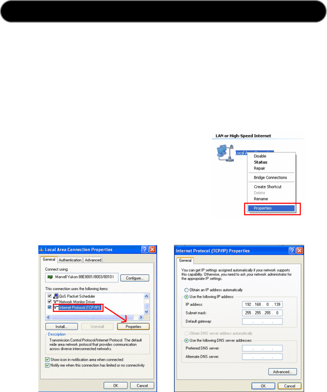
4. You may use following instruction to modify network settings.
Click Windows ¡ Control Panel¡ ¡ Network
Connection¡ ¡ Local Area Connection¡ ,
right-click on the icon and choose
Properties.
Choose ¡ Internet Protocol (TCP/IP)¡ , and
click Properties button.
Choose ¡Use the following IP address¡ ,
and type 192.168.0.X as IP address. The
Subnet mask is 255.255.255.0, then click OK.
APPENDIX
37
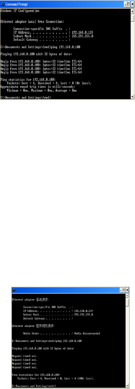
PING is a very useful MS-DOS command to
check if Network Camera is still responding
or if an IP address is available.
1. Click on ¡ Start¡ ¡ Run¡ and type
Cmd and press ENTER.
2. In the MS-DOS window, type Ping
192.168.0.100
3. For example, if your Network Camera
uses the IP address of 192.168.0.100,
you would type in: Ping 192.168.0.100 and press Enter.
If Network Camera online and using this address you will see:
Pinging 192.168.0.100 with 32 bytes of data:
Reply from 192.168.0.100: bytes=32 time<1ms TTL=64
Reply from 192.168.0.100: bytes=32 time<1ms TTL=64
Reply from 192.168.0.100: bytes=32 time<1ms TTL=64
Reply from 192.168.0.100: bytes=32 time<1ms TTL=64
Ping statistics for 192.168.0.100:
Packets: Sent = 4, Received = 4, Lost = 0 (0% loss), Approximate round trip
times in mill-seconds: Minimum = 0ms, Maximum = 0ms, Average = 0ms
If there is NO response on the address, you¡ll see the following:
Pinging 192.168.0.100 with 32 bytes of data:
Request timed out.
Request timed out.
Request timed out.
Request timed out.
Ping statistics for 192.168.0.100:
Packets: Sent = 4, Received = 0, Lost = 4
(100% loss),

38
Please check the following FAQ for a possible solution to issues encountered.
Frequency Asked Question
Q: What username and password can I accessing to the Network Camera for the
first time or just restored to factory default?
A:
Default username = admin
Default password = admin
Restore default IP address = 192.168.0.100
Q: What should I do if I forgot my username and password?
A:
Restore to factory default by pressing the ¡ Restore Default¡ button till the LEDs
has been turned on.
Q: Can the Network camera also work properly behind the firewall?
A:
¡ YES¡ , you¡ll need to adapt with ports and virtual IP forwarding from the setup of
the firewall.
Q: There is no video available from the web server !!
A:
ActiveX control may not be well installed. Please ensure ActiveX control has been
allowed to install from the Internet Explorere options menu. Please refer Internet
Explorer Security Settings to correctly configure your Internet Explorer.
Q: Internet Explorer displays the following message: ¡ This website wants to
install the following add-on: ¡ NetcamX¡ from ¡Leadtek Research Inc.¡. if you
trust the website and the add-on and want to install it, click here¡
A:
Restore the default IE security level as Medium or configure the individual settings
to allow downloading and scripts of singed ActiveX controls.
TROUBLE SHOOTING
39
Q: I cannot access the Network Camera from Web browser !
A:
1. Please use the command ¡ PING¡ to check the network connection. If the shown
response is ¡ Request timed out¡ , it may caused by the incorrect setting of IP
address.
2. Observe the Ethernet LED from the Network camera. It should be steady blue if
with a correct IP configuration. If not, check if both ends of the Ethernet cable are
well and properly attached.
3. Confirm that Network Camera¡s virtual/local IP address and ports have been
forwarded properly so that the browsing from internet can be successful. Please
refer to your camera HTTP port settings or router¡s user manual for detailed
configuration.

40
Changes or modifications to this unit not expressly approved by the party responsible for compliance
could void the user authority to operate the equipment.
1. This Transmitter must not be co-located or operating in conjunction with any other antenna or
transmitter.
2. For product available in the USA market, only channel 1~11 can be operated. Selection of other
channels is not possible.
IMPORTANCE NOTE:
20cm minimum distance has to be able to be maintained between the antenna and the users for the
host this module is integrated into. Under such configuration, the FCC radiation exposure limits set
forth for an population/uncontrolled environment can be satisfied.
Any changes or modifications not expressly approved by the manufacturer could void the user¡s
authority to operate this equipment.
Warning
FEDERAL COMMUNICATIONS COMMISSION INTERFERENCE STATEMENT
This equipment has been tested and found to comply with the limits for a Class B digital
device, pursuant to Part 15 of the FCC Rules. These limits are designed to provide
reasonable protection against harmful interference in a residential installation. This
equipment generates, uses and can radiate radio frequency energy and, if not installed
and used in accordance with the instructions, may cause harmful interference to radio
communications. However, there is no guarantee that interference will not occur in a
particular installation. If this equipment does cause harmful interference to radio or
television reception, which can be determined by turning the equipment off and on, the
user is encouraged to try to correct the interference by one or more of the following
measures:
– Reorient or relocate the receiving antenna.
– Increase the separation between the equipment and receiver.
– Connect the equipment into an outlet on a circuit different from that to which the
receiver is connected.
– Consult the dealer or an experienced radio/TV technician for help.
CAUTION:
Any changes or modifications not expressly approved by the party responsible for
compliance could void the user's authority to operate the equipment.
This device complies with Part 15 of the FCC Rules. Operation is subject to the following
two conditions:
(1) This device may not cause harmful interference and
(2) This device must accept any interference received, including interference that may
cause undesired operation.
RF exposure warning ·
This equipment must be installed and operated in accordance with provided instructions
and the antenna(s) used for this transmitter must be installed to provide a separation
distance of at least 20 cm from all persons and must not be co-located or operating in
conjunction with any other antenna or transmitter. End-users and installers must be
provide with antenna installation instructions and transmitter operating conditions for
satisfying RF exposure compliance.