Leap Devices RPP1TX770US Radio Popper P1 Transmitter User Manual

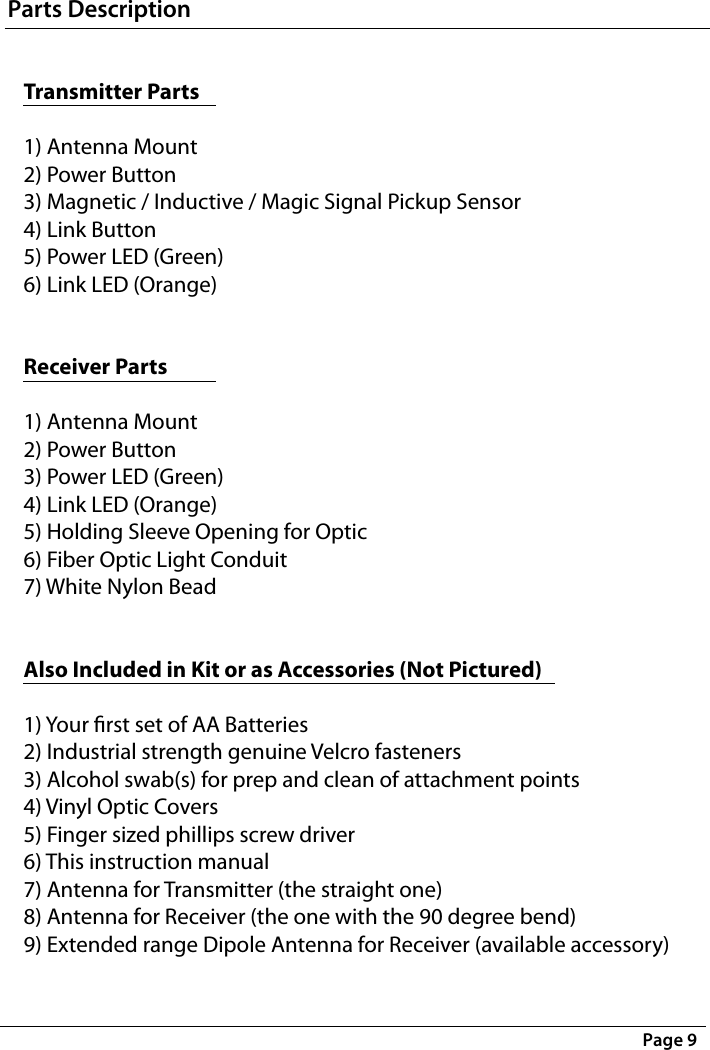
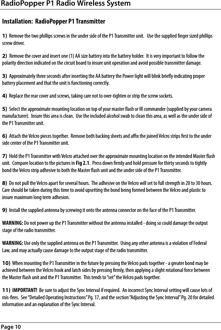
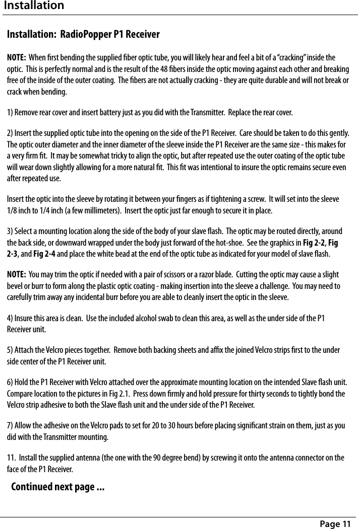
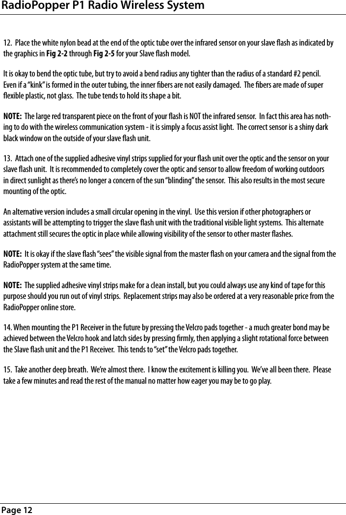
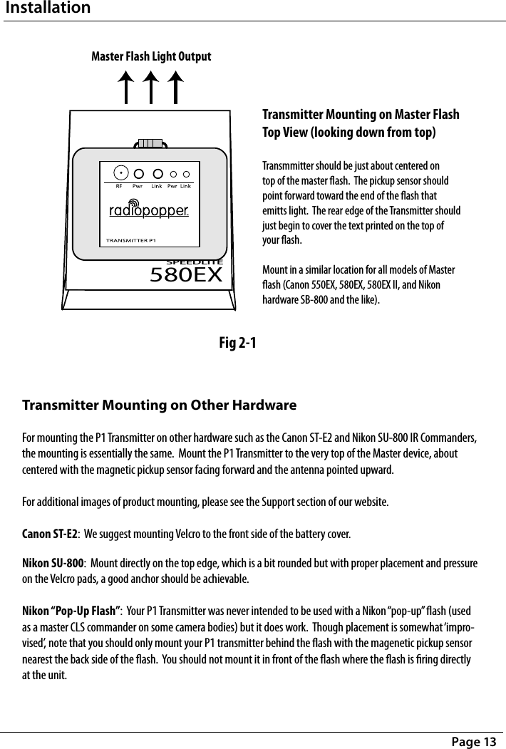
Leap Devices, LLC Radio Popper P1 Transmitter Users Manual

Users Manual

RadioPopper P1 Radio WirelessOwners Manual
Page 2RadioPopper is owned and manufactured by Leap Devices, LLC in Phoenix Arizona.  This product was designed, produced, and manufactured in the USA.PRODUCT PATENT PENDINGCopyright 2007-2008, Leap Devices LLC, All Rights ReservedLeap Devices LLC,  20987 N. John Wayne Pkwy. Suite B-104-207,  Maricopa, AZ 85239 FCC ID:  V4TRPP1TX770USThis device complies with Part 15 of the FCC Rules.  Operation is subject to the following two conditions:  (1) This device may not cause harmful interference and  (2) this device must accept any interference received, including interference that may cause undesired operation.FCC STATEMENTThis equipment has been tested and found to comply with the limits for a class B digital device, pursuant to part 15 of the FCC Rules.  These limits are designed to provide reason-able protection against harmful interference in a residential installation.  This equipment generates, uses and can radiate radio frequency energy and if not installed and used in accordance with the instructions, may cause harmful interference to radio communications.  However, there is no guarantee that interference will not occur in a particular installation. If this equipment does cause harmful interference to radio or television reception, which can be determined by turning the equipment o and on, the user is encouraged to try to correct the interference by one or more of the following measures:* Reorient or relocate the receiving antenna.* Increase the separation between the equipment and receiver.* Connect the equipment into an outlet on a circuit dierent from that to which the receiver is connected.* Consult the dealer or an experienced radio/TV technician for help.This equipment has been veried to comply with the limits for a class B computing device, pursuant to FCC Rules. Operation with non-approved equipment is likely to result in inter-ference to radio and TV reception.  The user is cautioned that changes and modications made to the equipment without the approval of manufacturer could void the user’s authority to operate this equipment.
Table of ContentsPage 3 Introduction . . . . . . . . . . . . . . . . . . . . . . . . . . . . . . . . . . . . . . . . . . . . . . . . . . . . .   Specications and Warnings  . . . . . . . . . . . . . . . . . . . . . . . . . . . . . . . . . . . . . . .   Parts Descriptions  . . . . . . . . . . . . . . . . . . . . . . . . . . . . . . . . . . . . . . . . . . . . . . . .  Installation  . . . . . . . . . . . . . . . . . . . . . . . . . . . . . . . . . . . . . . . . . . . . . . . . . . . . .   Slave Flash Optic Placement  . . . . . . . . . . . . . . . . . . . . . . . . . . . . . . . . . . . . . . .   Operating Instructions  . . . . . . . . . . . . . . . . . . . . . . . . . . . . . . . . . . . . . . . . . . .  Sync Interval Adjustment  . . . . . . . . . . . . . . . . . . . . . . . . . . . . . . . . . . . . . . . . .   Trouble Shooting  . . . . . . . . . . . . . . . . . . . . . . . . . . . . . . . . . . . . . . . . . . . . . . . .  Miscellaneous Tips  . . . . . . . . . . . . . . . . . . . . . . . . . . . . . . . . . . . . . . . . . . . . . .  4  68101416202226
Introduction Thank you for your purchase of the RadioPopper P1 wireless radio system.  This product represents much development and lots of thinking outside the box.  This system was developed by a “regular guy” with an electronics background - a wedding photographer from Arizona seeking to bridge the weak link of existing wireless systems - the need to maintain a “line of sight” between master and slave ash units.  We hope this new tool brings a great new dynamic to your work and how you use your lighting.In short, the RadioPopper P1 system allows you to use the automatic and high-speed sync functions built into your existing ash units without concern of whether or not the master and slave units can “see” each other.  You now have the ability to place your lights wherever you choose, then controlling the output power of each slave ash from the camera body manually or automatically via your camera’s ETTL or iTTL logic system.  It’s also the world’s rst product to eectively provide you high speed sync by radio.  That’s a major step forward.  Enjoy.Each aspect of this system has been well thought out to accomplish the nearly impossible task of reproducing an extremely fast communica-tion with exacting timing while at the same time remaining simple and intuitive for the user to install and operate.Please read this short manual entirely before installing or operating your RadioPopper P1 wireless system.  Proper installation is key to correct operation.  If you have any troubles along the way, feel free to call or email.RadioPopper P1 Radio Wireless SystemPage 4
How It WorksYour current master and slave wireless ash system continues to function just as it always has.  That’s the beauty and simplicity of the RadioPopper P1 system.  The RadioPopper P1 Transmitter “listens” to the light signal being created inside the master ash unit or remote commander on your camera’s hot shoe.  The P1 Transmitter sends this signal over the radio where it is read by the RadioPopper P1 Receiver.  The receiver then uses it’s own internal light source to “reproduce” this light signal.  The light is sent down the exible ber optic cable where it lights a small nylon bead at the end.  When this bead is placed over the infrared sensor on a slave ash - that slave ash responds to the “reproduced” light signal just as it normally would had it seen the light directly from the master ash.Installation couldn’t be more simple.  Just place the RadioPopper P1 Transmitter on top of your master ash or IR commander device using the included Velcro pads.  “Look Ma!  No wires!”  On the receiving end, add a P1 Receiver in a similar way, anchor the optic bead over the infrared sensor on your slave ash and you’re all done.  No wires or adaptors and no complicated system to re-learn.  Now just power up and shoot.  You’ve got remote control of your slave ashes, full ETTL and iTTL support along with high speed sync all the way to 1/8000 - by radio.NOTE:  When rst using the system you may develop “smile ache” in your cheeks, and you may feel the uncontrollable urge to giggle like a school girl.  This is perfectly normal.IntroductionPage 5
Compatible Hardware: The P1 System has been tested and found to be compatible with the following ash hardware.Canon Master / Commander Devices:SpeedLite 550EX(1), SpeedLite 580EX, SpeedLite 580EX II, SpeedLite Transmitter ST-E2  Canon Slave / Remote Devices:SpeedLites 420EX, 430EX, 550EX, 580EX, 580 EX IINikon Master / Commander Devices:SB-800 AF Speedlight, SU-800 Wireless Speedlight Commander,  Nikon “pop-up” ash used as a Commander(2)Nikon Slave / Remote Devices: SB-800 AF Speedlight, SB-600 AF Speedlight  Note(1): 550EX when used as a Master device must be set to ETTL channel 4 for greatest reliability, and ETTL channel 3 as an alternate.  550EX will not properly activate the radio system when set to ETTL channels 1 or 2.  550EX when used as a Slave device will operate on any ETTL channel.Note(2): The P1 system was never designed to work with the so called “pop-up” ash on some Nikon cameras, but it does indeed function and activate.  Mounting is somewhat “improvised” at the user’s discretion.   See the Release Notes at www.radiopopper.com or as provided as addendum to this user manual for more information.Specications: Both P1 Transmitter and P1 Receiver have similar specications.  Some specications are given once for this reason. Dimensions :  2.75” x 2.0” x 0.8”  (70mm x 50mm x 20mm)Weight:  2.5 ounces  / 70 grams (Including battery and antenna during normal operation)Battery:  “AA” Size Standard Battery / Alkaline, NiCad, or NiMH  / 0.9 volt to 1.6 volt Battery Life:  5 to 10 Hours continual active transmit time for Std Alkaline battery.  Longer with NiCad and NiMH.Radio Frequency: 916 Mhz ISM BandRadio Range:  Real world 100 ft to 500 ft depending on conditions and environment(3)Note(3): Please refer to the Release Notes at www.radiopopper.com or as provided as addendum to this user manual for more information including real world test results as to reliability rates at various ranges and in various environments.RadioPopper P1 Radio Wireless SystemPage 6
WARNING!!!    WARNING!!!    WARNING!!!!  PLEASE read this section in detail for important warnings and notices. USE ONLY THE SUPPLIED TRANSMITTER ANTENNA! Using any antenna other than the one supplied for use with your P1 Transmitter is a violation of Federal Law and may actually cause damage to the radio inside the transmitter.  This will also promptly void your warranty.  Your P1 Transmitter has been carefully tuned to broadcast the maximum signal strength allowable by law.  Altering the antenna characteristics is more likely to “de-tune” or degrade performance than to improve it. INSERT THE BATTERY IN THE CORRECT DIRECTION! Inserting the battery “backwards” could possibly damage the electronic components inside P1 Transmitter and P1 Receiver units.  The little “bump” on the AA always points away from the spring.  A graphic is provided at the base of the AA battery holder, as well as on the back side of the circuit board for reference.  Further, you should observe for the Power LED blinking a few  times  about three seconds after you insert the battery - indicating proper insertion.DO NOT REMOVE OR TAMPER WITH THE CIRCUIT BOARD! The delicate components on the circuit board are face-down for a reason.  Some of the components inside your P1 Transmitters and P1 Receivers are especially susceptible to electrostatic shock (they’re easily ‘zapped’ by static electricity) - just touching them could damage them.  Your circuit board is grounded to the case - as long as it’s not removed everything is safe.  Breaking the glue seal and removing or tampering with your circuit board will promptly void your warranty.YOUR POPPERS CAN’T SWIM!!  KEEP THEM DRY!! Of particular concern is the opening around the Power Button and Link Button.  If you dunk them, it may be too late.  If you’re caught outside in the rain, take care to keep these openings dry, as well as the access on the P1 Transmitter for the magnetic sensor in front.  Should you expose a RadioPopper to anything wet, remove the battery as quickly as possible and allow it 24 hours someplace dry to evaporate any water.  You may nd it has come back to life.  Again, allowing anything wet inside the case of your P1 Transmitter or P1 Receiver will promptly void the warranty.READ THE RELEASE NOTES! When you buy new computer software, it’s sent out with release notes.  You usually ignore them.  Please don’t ignore the RadioPopper release notes.  A printed notice may have been provided as an addendum to this user manual.  We also provide an updated version of the release notes on our website at www.radiopopper.com in the support section.  They’re kind of dry and not very interesting, but reading them may help you get even more enjoyment out of your RadioPopper P1 system.CONTACT US IF YOU GET CONFUSED! You’re a valued customer and we really do care about you.  (And not in that automated “your call is very important to us but we’re going to leave you on hold for an hour anyway” customer service recording sort of way).  Seriously - if you’ve got questions, we’re going to do everything possible to take care of you as quickly and as personally as possible.  The phone number is on our website and you can email us at  ‘support@radiopopper.com’Specications and WarningsPage 7
RadioPopper P1 Radio Wireless SystemPage 8123456P1 Transmitter7652 3 41P1 Receiver
Parts DescriptionPage 9Transmitter Parts1) Antenna Mount2) Power Button3) Magnetic / Inductive / Magic Signal Pickup Sensor4) Link Button5) Power LED (Green)6) Link LED (Orange)Receiver Parts1) Antenna Mount2) Power Button3) Power LED (Green) 4) Link LED (Orange)5) Holding Sleeve Opening for Optic6) Fiber Optic Light Conduit7) White Nylon BeadAlso Included in Kit or as Accessories (Not Pictured)  1) Your rst set of AA Batteries2) Industrial strength genuine Velcro fasteners3) Alcohol swab(s) for prep and clean of attachment points4) Vinyl Optic Covers5) Finger sized phillips screw driver6) This instruction manual7) Antenna for Transmitter (the straight one)8) Antenna for Receiver (the one with the 90 degree bend)9) Extended range Dipole Antenna for Receiver (available accessory)
Installation:  RadioPopper P1 Transmitter 1)  Remove the two phillips screws in the under side of the P1 Transmitter unit.   Use the supplied nger sized phillips screw driver.2)  Remove the cover and insert one (1) AA size battery into the battery holder.  It is very important to follow the polarity direction indicated on the circuit board to insure unit operation and avoid possible transmitter damage.3)  Approximately three seconds after inserting the AA battery the Power light will blink briey indicating proper battery placement and that the unit is functioning correctly.4)  Replace the rear cover and screws, taking care not to over-tighten or strip the screw sockets. 5)  Select the approximate mounting location on top of your master ash or IR commander (supplied by your camera manufacturer).  Insure this area is clean.  Use the included alcohol swab to clean this area, as well as the under side of the P1 Transmitter unit.6)  Attach the Velcro pieces together.  Remove both backing sheets and ax the joined Velcro strips rst to the under side center of the P1 Transmitter unit.7)  Hold the P1 Transmitter with Velcro attached over the approximate mounting location on the intended Master ash unit.  Compare location to the pictures in Fig 2.1.  Press down rmly and hold pressure for thirty seconds to tightly bond the Velcro strip adhesive to both the Master ash unit and the under side of the P1 Transmitter.8)  Do not pull the Velcro apart for several hours.  The adhesive on the Velcro will set to full strength in 20 to 30 hours. Care should be taken during this time to avoid upsetting the bond being formed between the Velcro and plastic to insure maximum long term adhesion.9)  Install the supplied antenna by screwing it onto the antenna connector on the face of the P1 Transmitter.WARNING: Do not power up the P1 Transmitter without the antenna installed - doing so could damage the output stage of the radio transmitter.WARNING: Use only the supplied antenna on the P1 Transmitter.  Using any other antenna is a violation of Federal Law, and may actually cause damage to the output stage of the radio transmitter.10)  When mounting the P1 Transmitter in the future by pressing the Velcro pads together - a greater bond may be achieved between the Velcro hook and latch sides by pressing rmly, then applying a slight rotational force between the Master ash unit and the P1 Transmitter.  This tends to “set” the Velcro pads together.11)  IMPORTANT!  Be sure to adjust the Sync Interval if required.  An incorrect Sync Interval setting will cause lots of mis-res.  See “Detailed Operating Instructions” Pg. 17, and the section “Adjusting the Sync Interval” Pg. 20 for detailed information and an explanation of the Sync Interval.RadioPopper P1 Radio Wireless SystemPage 10
Continued next page ...Installation:  RadioPopper P1 Receiver NOTE:  When rst bending the supplied ber optic tube, you will likely hear and feel a bit of a “cracking” inside the optic.  This is perfectly normal and is the result of the 48 bers inside the optic moving against each other and breaking free of the inside of the outer coating.  The bers are not actually cracking - they are quite durable and will not break or crack when bending.1) Remove rear cover and insert battery just as you did with the Transmitter.  Replace the rear cover.2) Insert the supplied optic tube into the opening on the side of the P1 Receiver.  Care should be taken to do this gently.  The optic outer diameter and the inner diameter of the sleeve inside the P1 Receiver are the same size - this makes for a very rm t.  It may be somewhat tricky to align the optic, but after repeated use the outer coating of the optic tube will wear down slightly allowing for a more natural t.  This t was intentional to insure the optic remains secure even after repeated use.Insert the optic into the sleeve by rotating it between your ngers as if tightening a screw.  It will set into the sleeve 1/8 inch to 1/4 inch (a few millimeters).  Insert the optic just far enough to secure it in place.3) Select a mounting location along the side of the body of your slave ash.  The optic may be routed directly, around the back side, or downward wrapped under the body just forward of the hot-shoe.  See the graphics in Fig 2-2, Fig 2-3, and Fig 2-4 and place the white bead at the end of the optic tube as indicated for your model of slave ash.NOTE:  You may trim the optic if needed with a pair of scissors or a razor blade.  Cutting the optic may cause a slight bevel or burr to form along the plastic optic coating - making insertion into the sleeve a challenge.  You may need to carefully trim away any incidental burr before you are able to cleanly insert the optic in the sleeve.4) Insure this area is clean.  Use the included alcohol swab to clean this area, as well as the under side of the P1 Receiver unit.5) Attach the Velcro pieces together.  Remove both backing sheets and ax the joined Velcro strips rst to the under side center of the P1 Receiver unit.6) Hold the P1 Receiver with Velcro attached over the approximate mounting location on the intended Slave ash unit.  Compare location to the pictures in Fig 2.1.  Press down rmly and hold pressure for thirty seconds to tightly bond the Velcro strip adhesive to both the Slave ash unit and the under side of the P1 Receiver.7) Allow the adhesive on the Velcro pads to set for 20 to 30 hours before placing signicant strain on them, just as you did with the Transmitter mounting.11.  Install the supplied antenna (the one with the 90 degree bend) by screwing it onto the antenna connector on the face of the P1 Receiver.InstallationPage 11
12.  Place the white nylon bead at the end of the optic tube over the infrared sensor on your slave ash as indicated by the graphics in Fig 2-2 through Fig 2-5 for your Slave ash model.It is okay to bend the optic tube, but try to avoid a bend radius any tighter than the radius of a standard #2 pencil.  Even if a “kink” is formed in the outer tubing, the inner bers are not easily damaged.  The bers are made of super exible plastic, not glass.  The tube tends to hold its shape a bit.NOTE:  The large red transparent piece on the front of your ash is NOT the infrared sensor.  In fact this area has noth-ing to do with the wireless communication system - it is simply a focus assist light.  The correct sensor is a shiny dark black window on the outside of your slave ash unit.13.  Attach one of the supplied adhesive vinyl strips supplied for your ash unit over the optic and the sensor on your slave ash unit.  It is recommended to completely cover the optic and sensor to allow freedom of working outdoors in direct sunlight as there’s no longer a concern of the sun “blinding” the sensor.  This also results in the most secure mounting of the optic.An alternative version includes a small circular opening in the vinyl.  Use this version if other photographers or assistants will be attempting to trigger the slave ash unit with the traditional visible light systems.  This alternate attachment still secures the optic in place while allowing visibility of the sensor to other master ashes.NOTE:  It is okay if the slave ash “sees” the visible signal from the master ash on your camera and the signal from the RadioPopper system at the same time.NOTE:  The supplied adhesive vinyl strips make for a clean install, but you could always use any kind of tape for this purpose should you run out of vinyl strips.  Replacement strips may also be ordered at a very reasonable price from the RadioPopper online store.14. When mounting the P1 Receiver in the future by pressing the Velcro pads together - a much greater bond may be achieved between the Velcro hook and latch sides by pressing rmly, then applying a slight rotational force between the Slave ash unit and the P1 Receiver.  This tends to “set” the Velcro pads together.15.  Take another deep breath.  We’re almost there.  I know the excitement is killing you.  We’ve all been there.  Please take a few minutes and read the rest of the manual no matter how eager you may be to go play.RadioPopper P1 Radio Wireless SystemPage 12
Transmitter Mounting on Other Hardware  For mounting the P1 Transmitter on other hardware such as the Canon ST-E2 and Nikon SU-800 IR Commanders, the mounting is essentially the same.  Mount the P1 Transmitter to the very top of the Master device, about centered with the magnetic pickup sensor facing forward and the antenna pointed upward.  For additional images of product mounting, please see the Support section of our website.  Canon ST-E2:  We suggest mounting Velcro to the front side of the battery cover.Nikon SU-800:  Mount directly on the top edge, which is a bit rounded but with proper placement and pressure on the Velcro pads, a good anchor should be achievable.  Nikon “Pop-Up Flash”:  Your P1 Transmitter was never intended to be used with a Nikon “pop-up” ash (used as a master CLS commander on some camera bodies) but it does work.  Though placement is somewhat ‘impro-vised’, note that you should only mount your P1 transmitter behind the ash with the magenetic pickup sensor nearest the back side of the ash.  You should not mount it in front of the ash where the ash is ring directly at the unit.SPEEDLITE580EXTransmitter Mounting on Master FlashTop View (looking down from top)Transmmitter should be just about centered ontop of the master ash.  The pickup sensor shouldpoint forward toward the end of the ash thatemitts light.  The rear edge of the Transmitter shouldjust begin to cover the text printed on the top ofyour ash.Mount in a similar location for all models of Masterash (Canon 550EX, 580EX, 580EX II, and Nikonhardware SB-800 and the like).InstallationPage 13Fig 2-1Master Flash Light Output
RadioPopper P1 Radio Wireless SystemPage 14Infrared SensorCenter nylon opticbead hereFocus assist lamp(has nothing to do with the visibleor radio wireless systems)Canon SpeedLite 420EX / 430EX / 580EXSlave Flash Optic PlacementInfrared SensorCenter nylon opticbead hereFocus assist lamp(has nothing to do with the visibleor radio wireless systems)Canon SpeedLite 580EX IISlave Flash Optic PlacementFig 2-2Canon SpeedLite 580EX IISlave Flash Optic PlacementFig 2-3Canon SpeedLite 430EX / 580EXSlave Flash Optic Placement
Slave Flash Optic PlacementPage 15Infrared SensorCenter nylon opticbead hereNOTE!!  This is NOT centeredon the black sensor area, it isplaced in the lower right corneras the 550EX sensor is o-centerFocus assist lamp(has nothing to do with the visibleor radio wireless systems)Canon SpeedLite 550EXSlave Flash Optic PlacementInfrared SensorCenter nylon opticbead hereFocus assist lamp(has nothing to do with the visibleor radio wireless systems)Nikon SB-800 / SB-600Slave Flash Optic PlacementFig 2-4Canon SpeedLite 550EXSlave Flash Optic PlacementFig 2-5Nikon SB-800 / SB-600 Slave Flash Optic Placement
Operation:  RadioPopper P1 Transmitter - QUICK REFERENCE Power On / O - Press and hold the Power Button for approx one second.  Green LED on indicates “power on”, Green LED o indicates “power o”.Radio Link - When the Link LED is lit, the radio is transmitting a carrier signal.Manual Radio Sleep - To ‘sleep’ the radio and stop broadcasting (to save battery or to share the frequency with a second photographer or assistant) - press the Link Button for one second until Link LED goes out.Manual Radio Wake - Tap the Link Button one time to re-activate the radio transmitting.Auto Radio Sleep - After 7 minutes of inactivity (no shots taken, timer not manually reset), the radio will stop broadcasting, the Link LED will go dark and the unit will sleep.Auto Radio Wake - If radio has begun to sleep automatically, activating your ash one time (taking a shot) or tapping the Link Button will wake the radio and resume transmitting.Timer Reset - Take a shot (activate the ash) or tap the Link Button to reset the 7 minute sleep timer.  Link LED will strobe momentarily indicating button press.Test Broadcast - Tap the Link Button one time, this resets the 7 minute timer and simultaneously sends a test broadcast.  Any P1 Receiver within range and operating properly will blink both of its LED’s together several times indicating clean reception and proper operation.Shot Indicator - After activating the Master Flash or IR Commander (you take a shot), the Link LED will momentarily strobe indicating a signal was received by the magnetic pickup sensor.  Operation:  RadioPopper P1 Receiver - QUICK  REFERENCE Power On / O - Press and hold the Power Button for approx one second.  Green LED on indicates “power on”, Green LED o indicates “power o”.Radio Link - The Link LED lights solid whenever the P1 Receiver is locked onto a carrier signal from a P1 Transmitter.Radio Not Linked - When radio link is lost, is interrupted, or is out of range, the P1 Receiver will franticly search the air waves attempting to re-aquire the radio signal.  Sleep Mode - If no signal is found, the P1 Receiver alternates between sleeping and looking for a signal, blinking the Power LED on each wake cycle.RadioPopper P1 Radio Wireless SystemPage 16
Operation:  Detailed P1 Transmitter Operating Instructions Power On / O Press and hold the Power Button for approx one second to alternate between Power On and Power O.Radio Link & Broadcast The RadioPopper P1 Transmitter has been designed to conserve power, to automatically stop broadcasting when not in use, and to allow several photographers to “share” a single radio signal through a system of easily turning the radio transmitter on and o without fully powering down the entire unit.  1) When power is rst turned on, the Link LED lights indicating the radio is broadcasting.  The Link LED is always lit whenever the radio is broadcasting, and is dark whenever the radio is not broadcasting.  2) When in an environment with multiple photographers, only one P1 Transmitter may be broadcasting at any given time within the same general area.  Manually Sleeping the Radio To temporarily deactivate the radio and stop broadcasting (either to save power or to allow another photographer to activate their own transmitter and control the same set of slave ashes) - simple press and hold the Link Button for one second to turn o the Link LED.  The radio is now sleeping and will not resume broadcasting until the Link LED is pressed again.  To wake the radio and resume broadcasting, tap the Link Button one time.  The Link LED should light indicating the radio is again broadcasting.Automatic Radio SleepThe P1 Transmitter will automatically stop broadcasting and go into sleep mode if there are no shots taken, or if the Link Button is not pressed for about seven minutes.  This feature insures the radio frequency will be clear for another photographer or assistant to use if the rst unit becomes inactive.  It also dramatically reduces power consumption if an active transmitter is forgotten about.  This automatic sleep feature may not be disabled.Resetting Sleep TimerThe sleep timer is reset each time a shot is taken.  It may also be reset manually by momentarily tapping the Link Button.  This also sends a test broadcast to all actively linked P1 Receiver units. Auto Radio Wake If the radio went to sleep as a result of the sleep timer running out, it will automatically wake up and resume normal broadcasting if the Master ash is activated by taking a shot.  The P1 Transmitter will not broadcast this rst activation so slave ashes will not activate.  It will however resume an active state to broadcast any follow-up shots.  You may also awake the radio after entering the automatic sleep mode by tapping the Link Button one time to resume normal broadcast operation.Operating InstructionsPage 17
Page 18RadioPopper P1 Radio Wireless SystemTimer Reset - Take a shot (activate the ash) or tap the Link Button to reset the 7 minute sleep timer.  Link LED will strobe momentarily indicating button press.Test Broadcast - Tap the Link Button one time, this resets the 7 minute timer and simultaneously sends a test broad-cast.  Any P1 Receiver within range and operating properly will blink both of its LED’s together several times indicating clean reception and proper operation.Shot Indicator - After activating the Master Flash or IR Commander (you take a shot), the Link LED will momentarily strobe indicating a signal was received by the magnetic pickup sensor.  Operation:  Detailed P1 Receiver Operating Instructions Power On / O Press and hold the Power Button for approx one second to alternate between Power On and Power O.  Radio Link Each P1 Receiver will indicate it has achieved a perfect radio link to an active P1 Transmitter by lighting the orange Link LED.  Whenever this LED is on, there exists a 100% perfectly clear connection between the P1 Transmitter and P1 Receiver.  The instant the carrier signal from the transmitter is lost, the Link LED will go dark, and will light again the instant a signal is again locked. You may observe the Link LED begin to strobe o and on when moving around.  This is normal as any degradation of the radio signal will be visible by the Link LED strobing on and o.  Once the P1 Transmitter and P1 Receiver are again stationary, the Link LED will generally stabilize.  This is also helpful for evaluating range in a given environment.  As you reach the usable limits of range the Link LED will begin to strobe o and on or may go out all together.  At the extremes of range you may also notice various odd behavior - both LED’s may blink together (as the random clicking in and out of the radio signal may trigger the P1 Receiver to think it has received a test broadcast from the P1 Transmitter), and your Slave ash may occasionally emit pops of light.  NOTE: If your ash behaves erratically or fails to activate after being placed near the extremes of range or in environments with lots of background radio interference, the erratic behavior of your slave ash can often be cleared by pressing the “Pilot” button on your Master Flash or IR Commander a few times.  Sending a “Pilot” signal should briey pop all slave ashes and also seems to clear their memory of any confusion caused by random pulses of light caused by stray radio signals.  Your P1 Receiver has been designed to react to, and attempt to relay any radio signal it receives in attempting to activate your Slave ash which causes some of the odd behavior above, but also makes it possible to activate the ash a certain percentage of the time even at extremely long ranges.  You should not observe much odd behavior in normal shooting situations at more modest ranges.
Operating InstructionsPage 19De-Link Sleep When a carrier radio signal from a P1 Transmitter is found and locked onto, the Power LED and Link LED light solid on the P1 Receiver.  When the carrier signal is lost even very briey, the Link LED will go dark as explained in the previous section.  When the signal is lost, your P1 Receiver will search frantically in attempting to re-aquire it.  It will keep this up for about 20 seconds.  It then begins to get bored and starts napping.  To conserve power, your P1 Receiver has been designed to enter a cycle of sleeping and waking when no carrier signal from an active P1 Transmitter is found.  At rst the naps are brief - about 1/4 second.  As time goes on and no signal is found, these naps extend to a maximum duration of 3 seconds each.  During each “sleep” cycle, the Power LED will go dark, and upon each waking - your P1 Receiver will power up the radio and sni the air waves to see if a carrier signal exists from a P1 Transmitter.  The Power LED will blink during the wake cycle.  If no carrier signal is found, the P1 Receiver goes back to sleep.  As soon as a signal is found and re-aquired, the Link LED is again lit, and loosing this signal will again cause the P1 Receiver to quickly search for it, and eventually resume a napping pattern.  This wake and nap pattern was designed to conserve battery power when no link exists.  You may use this to setup a Slave ash several hours before you actually need it and allow your P1 Receiver to essentially “stand by” without much battery use.  Some Slave ashes will also go into standby and will wake when seeing the signal from the P1 Receiver.  Please test on your own to see if your Slave ash is capable of awaking from standby when seeing a signal.  NOTE:  When attempting to turn o a napping P1 Receiver, the one second you press and hold the Power Button to cause the power down will not begin until the next timed “wake” cycle of the P1 Receiver - when it is sleeping, it won’t see your button press so you may need to hold the button longer than usual to power o the unit.
Page 20RadioPopper P1 Radio Wireless SystemAdjusting the Sync IntervalBefore we describe how to adjust the Sync Interval, some background explanation is in order.  If you’re the non-technical type, skip ahead to the next page.  This sounds pretty complicated and scary, but it’s not really - nothing to be afraid of.  In most cases you’ll make this adjustment once (if at all) then forget about it.In order for the slave ash to respond correctly to the “reproduced” light signal from the P1 Receiver, the timing of the reproduced signal must be exceptionally accurate.  To insure the original signal and the reproduced signal match perfectly, both the P1 Transmitter and the P1 Receiver must operate on the same timing clock, and these two clocks must remain in sync with each other to about a millionth of a second.To accomplish this, the P1 Transmitter sends out a carrier signal at a particular timing and the receivers use this signal to maintain their timing clocks synchronized to that of the transmitter.It is important that the timing of this “clock” signal be adjusted so that it does not conict with the timing of the light pulses emitted by your Master Flash or IR Commander.  There’s a lot of math and a thirty minute discussion behind this so we’ll spare you the details.  Suce to say your P1 system may require a quick and painless adjustment to this timing during rst use, or if you make any major changes to your gear.The timing of the light pulses created by your Master Flash or IR Commander are determined by a combination of what type of camera body you’re using along with what device you’re using as your Master Flash or IR Commander on the hot shoe.  Because this can vary somewhat depending on your particular hardware setup, you have the ability to adjust this timing interval to iron out any conict that may exist.How do I know if the Sync Interval needs adjusting?The sync interval may be adjusted to a setting of 1 to 10.  Your P1 Transmitter ships on setting “10” which works well for most hardware.  If your slave ash is being activated correctly by radio, you likely will not need to adjust this setting.Indicating an adjustment is required - you will see your slave ash emit a brief burst of light, but no ash will be visible in your actual exposure.  What you are seeing is your slave ash emitting a pre-ash but no main ash.  If you observe this behavior in a majority of your shots - adjusting the Sync Interval will likely solve the problem.You may need to re-adjust this interval if you go to a dierent class of camera body, a dierent brand, or if you begin shooting lots of ash groups (you’re using A, B, and C ash groups for example).With any given mix of camera body and slave ash hardware, there will likely be several Sync Interval settings that will not work and several that will.  In any case, you should be able to nd at least one setting that works reliably for your hardware.
Sync Interval AdjustmentPage 21Adjusting the Sync Interval - Instructions If your P1 system appears to be operating correctly - you’re getting reliable triggering of slave ashes and you see the ash adding light to your actual exposures, then you should not make any change to the Sync Interval.  The Sync Interval may be adjusted to a setting of between “1” and “10”.  Your P1 Transmitter ships on a default setting of “10” which works well with most hardware.  Starting Adjustment Press and hold both Power Button and Link Button on your P1 Transmitter at the same time for approximately one second until both Power LED and Link LED strobe together.  Release Power Button and Link Button.  Current Interval Display Your P1 Transmitter will indicate the current Sync Interval by blinking the Link LED in sets corresponding to the current adjustment point.  Sets of 4 blinks for example represent a Sync Interval adjustment of “4”.  There is a clear pause between sets of blinks.  Count the blinks to determine the current adjustment.  Increment Adjustment To increment the current setting, press the Link Button briey.  The Power LED will light during the button press and the P1 Transmitter will increment its count.  Each press of the Link Button will increment the count by one up to setting “10”, then it will loop back to setting “1”.  Lock-In New AdjustmentOnce the new setting is reached, lock it in by pressing the Power Button one time.  The P1 Transmitter will conrm by blinking both LED’s together a number of times corresponding to the new Sync Interval setting.  The P1 Transmitter will then resume normal operation.  Resuming Normal OperationP1 Receivers are designed to nd and lock onto any Sync Interval carrier signal - they require no adjustment after changing this setting on your P1 Transmitter.  They should automatically re-link to your P1 Transmitter.  Choosing a Setting So which setting should you choose??  There’s a bit of trial and error involved.  Again, “10” works great for most hard-ware.  You should sequentially increment the setting by 1 step at a time and test re the system at each setting.  You should eventually nd a setting that is reliable in triggering  your slave ashes.  Suggested Settings In our testing we’ve found setting “10” (which is the default setting) works with the greatest variety of hardware.  A few suggested alternates for Canon are 4 and 5, and Nikon setting 4 works well.
Page 22RadioPopper P1 Radio Wireless SystemRange and ReliabilityPlease see the Release Notes included with this manual or as available on our website at www.radiopopper.com for a more detailed discussion of all the specics regarding range and reliability.It is important to understand the limitations of your P1 system so you may comfortably work within them.  You will have occasional misres which may be caused by a number of factors.  Reading through this section will go a long way to maximizing reliability and system usefulness in your type of photography.How ETTL and iTTL Work Many of the misre events you may experience are directly attributable to the ETTL and iTTL systems built into the ashes themselves, rather than the P1 radio system.  Please read this section to familiarize yourself with how your ash system operates.Your ETTL or iTTL system works by causing the wireless Slave ash to emit two separate bursts of light.  The rst burst, called a “pre-ash”, is a dim ash of a known amount of light.  Before your camera’s shutter opens, your camera’s meter-ing system measures this rst “pre-ash” and based upon it, calculates the correct amount of light needed to properly expose your image.  Your camera then opens the shutter and commands the wireless Slave ash to emit the second burst, the “Main Flash” that actually exposes your image.Pre-Flash with no Main-FlashOne of the most common mis-re events you are likely to observe is the wireless Slave ash emitting a short “pre-ash”, but you see no ash contributing to your actual exposure when looking at the picture after the shot in your camera’s display.  It may appear your ash is “ring”, but you don’t see any ash in your exposed image.NOTE: If you are using high speed sync, please refer ahead to the High Speed Sync note on Page 26.This  type of mis-re may be caused by a combination of several factors and will likely occur in a certain percentage of exposures.  NOTE:  This type of mis-re will only happen if you are actually using the ETTL or iTTL function of your camera (the “automatic ash” mode).  Some camera bodies, Master Flash devices or IR Controller devices allow you to remotely adjust the power of your wireless slave ashes manually.  In this case they re at the prescribed power level with each shot without performing a “pre-ash”.  You may nd greatest system reliability especially at longer ranges when setting your ashes to this manual mode.  Please refer to your camera and ash owner’s manuals as dierent hardware may vary greatly regarding features for remotely setting the power level of slave ashes.  If this paragraph confused you, disregard and just set your ashes so they display “ETTL”, “iTTL”, or something similar in their display.1. If you’re getting a lot of these misres (anything much over 10% of your images), you should adjust the Sync Interval setting on the transmitter (Page 20).  A bit of trial and error here should dramatically improve reliability.2. In much testing of ETTL and iTTL systems  without the P1 System installed, we’ve  found a misre rate of 5% or more when the Master ash is red directly into the Slave ash at a range of a few feet.  It is clear that even in the most ideal
Trouble ShootingPage 23situations, a certain number of mis-res will occur purely attributable to inconsistencies in the Master and Slave ash system itself.  As the RadioPopper P1 system simply repeats the signal with a high degree of accuracy, these mis-res attributable solely to the ash system itself will still happen.3. Your camera’s metering system must be able to observe the amount of light being emitted by the wireless Slave during the Pre-Flash.  If it doesn’t see this light, it will not command the ash to emit a Main Flash.  If you’re shooting at long ranges (and we know you’ll go outside and try it down the street - right?) - remember you’re shooting much beyond the range your camera’s metering system was intended to be able to measure this Pre-Flash.  If you’re shooting with anything other than a tight telephoto lens at these longer ranges, or if the Slave ash is hidden to such an extent that it contributes very little light, you’ll notice much reduced reliability.  In these situations, you should set your Slave ash to operate in Manual mode.  Some Master ash devices allow you to remotely adjust the setting of the wireless Slave from the Master device.  This (with most hardware) eliminates the whole pre-ash logic which should greatly improve reliability in these longer range situations.4. Consider the Recycle Time of your remote ashes.  When shooting wireless, you tend to shoot faster than usual without waiting for a full recycle.  You’ve also probably got that ash placed some distance away from the subject which means it’s ring at a higher power, causing further delay to recycle.  This also applies with High Speed Sync - which tends to make your Slave ash cycle more deeply.A ash that is not completely recycled will often still emit a pre-ash but won’t have enough ‘charge’ to re the main ash.  Also note that the red blinking “beacon” light on the front of the ash (on Canon hardware) often starts blinking before the ash is actually fully recycled.  You may need to wait a couple seconds after this beacon starts blinking before actually taking the next shot.Sidenote:  We HIGHLY recommend PowerEx rechargeable NiMH batteries for your ashes.  They cycle way faster than anything else o the shelf, even with the external battery pack.  They haven’t paid us to say that, we just think they’re awesome.  Get them at mahaenergy.com.5. Sometimes a Slave ash may get confused and stop responding correctly.  No kidding.  This happens without the P1 Radio system also - many people have had the experience of a Slave ash acting “funny” when using the ‘line of sight’ system even without the RadioPopper P1 system.This “getting confused” seems to have more to do with the Slave ash than the P1 Radio.  To “un-confuse” it, try pressing the Pilot button on the back of your Master Flash or IR Commander.  This should cause all slave ashes to emit a short pop of light indicating they are alive.  This also seems to “clear” any confusion.  Do this Pilot operation a couple times to be sure.6. Try changing the ETTL channel on your ashes.  This sounds strange, but even before the RadioPopper system came along, many photographers have found greater reliability on certain ETTL channels.  If you’re using a SpeedLite 550EX as your master, set it to ETTL channel 4, or 3 as an alternate as it won’t work on ETTL channels 1 or 2.7. Check your batteries.  All of them.  There is no “auto cut o” when the batteries in your P1 Transmitter and P1 Receivers
Page 24RadioPopper P1 Radio Wireless Systemstart to die.  You will start seeing increased numbers of mis-res when either unit begins to run low.  As the drain is similar on both units, it’s a good idea to always replace batteries in all units at the same time.  Also note the battery in your Master Flash or IR Commander may be getting low.8. Mis-res will increase with greater range.  In normal shooting situations, activation and operation should be pretty reliable.  As you begin to put objects, walls, buildings, and city streets between P1 units, you will at some point notice an increase in the number of mis-res.9. Some mis-res are unavoidable.  Due to the extreme speed at which the P1 system must operate, there is no error checking or repeating of the radio signal as with other radio based ash triggering products.  Unfortunately, the ash manufacturers chose to time the visual pulses of light impossibly close together.  The P1 system reads these pulses of light and does it’s best to relay them.  The message is sent, and generally it’s received and operates the slave ash cor-rectly.  See the Release Notes for a more detailed discussion.The source of most mis-res attributable to the P1 System is background radio interference.   We have built a nearly perfectly tuned radio system into the RadioPopper P1 and it uses a frequency not shared by many other devices (it’s nowhere near the frequency used by wireless phones for example).  However, other electronic devices present in most environments emit a certain amount of unintentional radio waves.  This background radiation will foul a certain number of shots, but the actual number should be fairly minimal and overall, you should nd performance quite reliable. No Flash at All The second mis-re event you may observe is the Slave ash not emitting any light at all.  This is likely caused by incorrect conguration of the ash system itself (aside from the RadioPopper P1 system) or a problem with system installation.1.  Uncover the infrared sensor on your Slave ash (if you’ve used an adhesive cover or tape to attach the P1 Receiver optic over the sensor).  Power o the P1 Transmitter and Receiver and attempt to re the Slave ash at short range using the normal line of sight system.  It must operate correctly using the line of sight system at short range before it will operate using the P1 System as the P1 is simply repeating the visible signal.  See the owner’s manual that came with your ash and camera body to insure you’ve congured your existing hardware correctly.  You may want to double check the Master and Slave units are set to the same ETTL channels, that the ash on the hot-shoe is set to “Master” and the remote ash is set to “Slave” and so on.Once your ashes are operating correctly using the line of sight system, power up your P1 Transmitter and P1 Receivers and continue....2.  When the radio is activated on the P1 Transmitter (see Operating Instructions earlier in this manual), observe the Link LED (orange) is lit on the P1 Transmitter.  This should also cause the Link LED to light on the P1 Receiver indicating there is a good radio link established between the two units.  If the Link LED is lit on your P1 Transmitter, but the Link LED does not light on your P1 Receiver(s), the receiver(s) may be
Trouble ShootingPage 25out of range, there may exist some background radio interference in your environment preventing a good link (including another P1 Transmitter being used by another photographer near by), or one of your units may be damaged.  Move to another location and try it again to eliminate the possibility of some source of radio interference operating near to you.3.  When a good link is established (the Link LED lights and remains lit solid on the P1 Receiver), tap the Link Button on the P1 Transmitter one time quickly.  This should cause the Link LED on the P1 Transmitter to strobe.  It will also send a test message meeting the same timing requirements of an actual ash trigger event to all active P1 Receivers.  If this message is received correctly, they will blink both of their LED’s together several times.This indicates a good radio connection exists and the units are clearly communicating with speed an accuracy that should allow normal operation.4.  Install your P1 Transmitter on top of your Master Flash or IR Commander as described in the Installation Instructions section of this manual.  When you take a shot, the Link LED on the P1 Transmitter should strobe briey following the shot.  This indicates the magnetic sensor on the P1 Transmitter is picking up a signal from your Master Flash or IR Commander.  It does not necessarily mean the signal is complete or correct, simply that a signal is being received.If the Link LED of the P1 Transmitter does not strobe when shooting, re-check your installation and that the batteries in your P1 Transmitter are good, as well as checking the batteries in your IR Commander.  You may try adjusting the placement of the P1 Transmitter on top of your Maser device slightly, though much adjustment should not be required.  Even if the Link LED on the P1 Transmitter does strobe after a shot, it is possible it may not be picking up the complete signal from your Master Flash or IR Commander.  Again, this is rare but possible. The sensor (the “bead” hanging on the side of the P1 Transmitter) should be 1/2” to 1” above the plastic surface of your ash, and should be placed rear of the front edge of the ash 1/2” to 1”.  Moving this sensor closer to the ash lens (where the light comes out) may actually degrade performance.  The magnetic signal is strongest and most consistent a bit further back from the ash lens and a short distance above the plastic exterior of the ash.5. Check the placement of the nylon bead at the end of the optic tube on the P1 Receiver.  Insure it is placed over the infrared sensor of your ash as per the Installation Instructions in this manual.  It should NOT be placed over the red plastic piece on your slave ash - this is not the infrared sensor.  On the SpeedLite 550EX used as a slave note the infrared sensor is not centered on the black window, it’s in the lower right corner.  See Fig XX in this manual.Also check how the optic is inserted into the sleeve on the side of the P1 Receiver. 6.  Make sure there is no excessive bend in the optic tube extending away from the P1 Receiver.  A bend any tighter than what would wrap around your nger should be avoided.  Too tight of a radius and light may not travel through the tube as eciently as designed and could lead to mis-res.
Page 26RadioPopper P1 Radio Wireless SystemTrouble Shooting other Miscellaneous Issues  One of my P1’s have become non-responsive You may observe a P1 unit “freeze up” and become non-responsive to button presses, won’t turn o, won’t de-link or re-link and so on.  This is usually caused by a low battery.  There is no “low voltage cuto” in either unit.  We’ve designed them to allow the battery to continue to drain until some part of the circuitry can no longer function to allow longest use of a battery, or to squeeze the last bit of power when you’re in a tight shooting situation and can’t replace batteries.A new Alkaline battery (the non-rechargeable ones you get from the store) should last 5 to 10 hours of continual transmit time.  Rechargables will probably go longer, but remember that rechargeable batteries tend to naturally drain and die o on their own after a couple days of non-use.High Speed Sync - I see the ash re, but the image is still dark This may also be seen as a “pre-ash with no main ash” type of mis-re as described above, but is not actually a mis-re at all.  When playing with High Speed Sync it must be realized that your ash produces an exponentially reduced amount of light the higher you push the shutter speed.  If you’re shooting at 1/8000 (and we know you’ll try it) your ash is emitting very little light.   If you place the ash much distance from the subject or through a diuser, you may not see the contribution of light to your image, even though it is indeed ring correctly.  Try reducing your shutter speed or getting the ash closer to the subject.  Dealing with Radio Interfearance It is easy to tell if you are in an environment with background radio interfearance.  If your slave ashes begin spurrati-cally emitting short or full bursts of light (without you triggering them), or if you notice the Link light on your P1 Receiv-ers is ickering, there is likely some background interfearnance present.  Your P1 Receiver is highly sensitive to uctuations in the radio signal which give it the required high speed performance.  It is also tuned to a very narrow band which means it tends to reject most forms of radio interfearnance.  Occasionally, you will still encouter situations where some source of background radio signals may cause interfearance.  This interfearance may be another radio transmitter, or it may be another electronic device.  One common source is ourescent light bulbs which are begnining to fail, and old computer monitors.  Genearlly, you can avoid this interfear-ance by moving out of the immediate area - sometimes moving just ten or fteen feet is enough to restore normal reliable operation.  Your P1 system is NOT eected by cellular phones, 900mhz wireless phones or pagers - these devices are tuned well away from the frequency used by the P1 system.
Miscellaneous TipsPage 27Miscellaneous Tips & Answers to Frequently Asked Questions  Tip / Question: Antenna Placement Does the antenna have to point straight up?  No.  You will achieve the greatest range with both antennas pointed straight up.  However in most common shooting situations, the radio signal reects around the environment enough that either antenna can be pointed any direction and still reliably operate.  Pointing the antennas straight up is more im-portant at longer ranges and in wide open areas (where there are no walls or buildings for the signal to bounce o of).The P1 Transmitter antenna emits the least amount of energy straight down.  If you tilt your camera to the left for a vertical shot, a P1 Receiver placed on your right may loose the signal as the transmitter signal must go through your ash and camera body.  You’re only likely to experience this in wide open areas and at somewhat longer ranges.Tip: Getting Maximum Range If you really want to maximize range for an exceptionally long shot, set your ash in a manual mode (no ETTL or iTTL, eliminating the need for the camera to see a “pre-ash”).  Point the P1 Transmitter antenna straight up.  Point your P1 Receiver antenna straight up and check that it is on the same side of the ash as the side you’re shooting from (so the signal doesn’t have to travel through the ash itself to reach the antenna), and attempt to elevate both transmitter and receiver o the ground a bit.  You may also order a high gain Dipole antenna from our online store for your P1 Receivers which will give you a bit more range.Tip:  Maximizing Radio Performance Radio signals sometimes behave in strange ways - understanding how your radio system works will help insure predictable performance.  Generally, radio signals emit in every direction and bounce o of surrounding structures such that little care is needed in the placement or orientation of your hardware, but certain situations will require more consideration.  Particularly in wide open spaces with little or no metallic objects (cars, siding, structures, etc.) the radio signals emit outward and have nothing to “bounce o of”.  In these situations some care must be taken to avoid placing dense objects between transmitter and receiver, particularly groups of people, tile, and concrete structures.    For example, in an open eld, placing a P1 Receiver behind a brick and concreate wall - even just a few feet away may lead to spurratic radio performance as the radio signals won’t penetrate the wall.  If on the other hand this same scene was set next to a parking lot with lots of metal cars, the radio signal would ‘reect’ o those cars and likely bounce back to the other side of the wall.  If there are no dense objects between the units, it is possible to achieve ranges of 300+ ft in open spaces that are clear of background radio interfearance.  Generally in enclosed environments this is not an issue as there is sucient structure to reect radio signals in every direction.
Page 26RadioPopper P1 Radio Wireless System
Limited WarrantyPage 27
Copyright 2007-2008, Leap Devices LLC, All Rights Reserved

Navigation menu