Leap Devices SKT1 SK Meter Module User Manual
Leap Devices, LLC SK Meter Module
User Manual
SK Tx Module
Technical Guide
Connection between the SK Tx module and a host
device is provided by a single 12 pin header. The pin
out and operation of pins is described below.
Pin 1 - DC Power Supply 3.3v to 6.0v
Pin 2 - Ground
Pin 3 - General Input
Pin 4 - General Output
Pin 5 - Not Used
Pin 6 - Not Used
Pin 7 - Serial Data Output (9600 bps, N81)
Pin 8 - Serial Data Input (9600 bps, N81)
Pin 9 - Reset (Enable High, Disable/Powerdown Low)
Pin 10, Pin 11, Pin 12 - Not Connected, Not Used
Module Installation
The SK Tx module may be installed in a battery pow-
ered host device. The SK Tx module is not permitted
to be installed in any host device that connects to
mains power (for example to a wall outlet).
To maintain regulatory authorization to use the SK
Tx module in a host device, following the installation
of the SK Tx module into a host device, it is required
that the included label sating “This device includes
FCC ID: V4TSKT1” be applied to an exterior non-
removable surface of the host device. Do not apply
to a battery door of the host device. An example of
this label is provided on the next page of this guide.
This guide includes technical specication of the SK
Tx Module, as well as guidelines for installation of
the module into a host device.
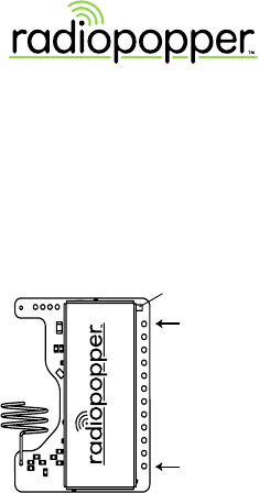
Module Connections
SK METER MODULE
Model: SK Tx FCC ID: V4TSKT1 IC: 7822A-SKT1
Green Light
Pin 1
Pin 12

FCC STATEMENT
This equipment has been tested and found to comply with the
limits for a class B digital device, pursuant to part 15 of the FCC
Rules. These limits are designed to provide reasonable protection
against harmful interference in a residential installation. This
equipment generates, uses and can radiate radio frequency energy
and if not installed and used in accordance with the instructions,
may cause harmful interference to radio communications. However,
there is no guarantee that interference will not occur in a particular
installation. If this equipment does cause harmful interference to
radio or television reception, which can be determined by turning
the equipment o and on, the user is encouraged to try to correct
the interference by one or more of the following measures:
* Reorient or relocate the receiving antenna.
* Increase the separation between the equipment and receiver.
* Connect the equipment into an outlet on a circuit dierent from
that to which the receiver is connected.
* Consult the dealer or an experienced radio/TV technician for
help.
Operation with non-approved equipment is likely to result in
interference to radio and TV reception. The user is cautioned that
changes and modications made to the equipment without the
approval of manufacturer could void the user’s authority to operate
this equipment.
Important Note: To comply with FCC RF exposure compliance
requirements, the following antenna installation and device
operating congurations must be satised - This device and its
antenna(s) must not be co-located or operating in conjunction
with any other antenna or transmitter.
Support
Need help? We’re happy to oer support.
Online Support: radiopopper.com/support
Email: support@radiopopper.com
Phone: 360.713.0776
Specications
Supply Voltage:
Typical 3.3 Volts DC
May be supplied with 3.3v to 6.0v DC
Maximum Voltage Supplied to Pins:
No more than 0.3 volts above supply voltage.
Radio Frequency:
902-928 MHz, ISM Band
FCC ID: V4TSKT1
This device complies with Part 15 of the FCC Rules.
Operation is subject to the following two conditions:
(1) This device may not cause harmful interference and
(2) this device must accept any interference received,
including interference that may cause undesired operation.
This device contains
FCC ID: V4TSKT1
Model: SK Tx IC: 7822A-SKT1
Example of label. This label was shipped in the
packaging with the SK Tx module. Place this label
on a non-removable surface on the exterior of the
host device.